EP2836347B1 - Injection moulded container made of plastic - Google Patents
Injection moulded container made of plastic Download PDFInfo
- Publication number
- EP2836347B1 EP2836347B1 EP13718525.2A EP13718525A EP2836347B1 EP 2836347 B1 EP2836347 B1 EP 2836347B1 EP 13718525 A EP13718525 A EP 13718525A EP 2836347 B1 EP2836347 B1 EP 2836347B1
- Authority
- EP
- European Patent Office
- Prior art keywords
- container
- thickenings
- ridge
- wall
- region
- Prior art date
- Legal status (The legal status is an assumption and is not a legal conclusion. Google has not performed a legal analysis and makes no representation as to the accuracy of the status listed.)
- Not-in-force
Links
Images
Classifications
-
- B—PERFORMING OPERATIONS; TRANSPORTING
- B29—WORKING OF PLASTICS; WORKING OF SUBSTANCES IN A PLASTIC STATE IN GENERAL
- B29C—SHAPING OR JOINING OF PLASTICS; SHAPING OF MATERIAL IN A PLASTIC STATE, NOT OTHERWISE PROVIDED FOR; AFTER-TREATMENT OF THE SHAPED PRODUCTS, e.g. REPAIRING
- B29C45/00—Injection moulding, i.e. forcing the required volume of moulding material through a nozzle into a closed mould; Apparatus therefor
- B29C45/0046—Details relating to the filling pattern or flow paths or flow characteristics of moulding material in the mould cavity
-
- B—PERFORMING OPERATIONS; TRANSPORTING
- B65—CONVEYING; PACKING; STORING; HANDLING THIN OR FILAMENTARY MATERIAL
- B65D—CONTAINERS FOR STORAGE OR TRANSPORT OF ARTICLES OR MATERIALS, e.g. BAGS, BARRELS, BOTTLES, BOXES, CANS, CARTONS, CRATES, DRUMS, JARS, TANKS, HOPPERS, FORWARDING CONTAINERS; ACCESSORIES, CLOSURES, OR FITTINGS THEREFOR; PACKAGING ELEMENTS; PACKAGES
- B65D1/00—Containers having bodies formed in one piece, e.g. by casting metallic material, by moulding plastics, by blowing vitreous material, by throwing ceramic material, by moulding pulped fibrous material, by deep-drawing operations performed on sheet material
- B65D1/12—Cans, casks, barrels, or drums
- B65D1/14—Cans, casks, barrels, or drums characterised by shape
- B65D1/16—Cans, casks, barrels, or drums characterised by shape of curved cross-section, e.g. cylindrical
-
- B—PERFORMING OPERATIONS; TRANSPORTING
- B65—CONVEYING; PACKING; STORING; HANDLING THIN OR FILAMENTARY MATERIAL
- B65D—CONTAINERS FOR STORAGE OR TRANSPORT OF ARTICLES OR MATERIALS, e.g. BAGS, BARRELS, BOTTLES, BOXES, CANS, CARTONS, CRATES, DRUMS, JARS, TANKS, HOPPERS, FORWARDING CONTAINERS; ACCESSORIES, CLOSURES, OR FITTINGS THEREFOR; PACKAGING ELEMENTS; PACKAGES
- B65D1/00—Containers having bodies formed in one piece, e.g. by casting metallic material, by moulding plastics, by blowing vitreous material, by throwing ceramic material, by moulding pulped fibrous material, by deep-drawing operations performed on sheet material
- B65D1/40—Details of walls
- B65D1/42—Reinforcing or strengthening parts or members
- B65D1/44—Corrugations
-
- B—PERFORMING OPERATIONS; TRANSPORTING
- B65—CONVEYING; PACKING; STORING; HANDLING THIN OR FILAMENTARY MATERIAL
- B65D—CONTAINERS FOR STORAGE OR TRANSPORT OF ARTICLES OR MATERIALS, e.g. BAGS, BARRELS, BOTTLES, BOXES, CANS, CARTONS, CRATES, DRUMS, JARS, TANKS, HOPPERS, FORWARDING CONTAINERS; ACCESSORIES, CLOSURES, OR FITTINGS THEREFOR; PACKAGING ELEMENTS; PACKAGES
- B65D25/00—Details of other kinds or types of rigid or semi-rigid containers
- B65D25/20—External fittings
- B65D25/205—Means for the attachment of labels, cards, coupons or the like
-
- B—PERFORMING OPERATIONS; TRANSPORTING
- B29—WORKING OF PLASTICS; WORKING OF SUBSTANCES IN A PLASTIC STATE IN GENERAL
- B29C—SHAPING OR JOINING OF PLASTICS; SHAPING OF MATERIAL IN A PLASTIC STATE, NOT OTHERWISE PROVIDED FOR; AFTER-TREATMENT OF THE SHAPED PRODUCTS, e.g. REPAIRING
- B29C45/00—Injection moulding, i.e. forcing the required volume of moulding material through a nozzle into a closed mould; Apparatus therefor
- B29C45/14—Injection moulding, i.e. forcing the required volume of moulding material through a nozzle into a closed mould; Apparatus therefor incorporating preformed parts or layers, e.g. injection moulding around inserts or for coating articles
- B29C2045/1486—Details, accessories and auxiliary operations
- B29C2045/14901—Coating a sheet-like insert smaller than the dimensions of the adjacent mould wall
- B29C2045/14918—Coating a sheet-like insert smaller than the dimensions of the adjacent mould wall in-mould-labelling
-
- B—PERFORMING OPERATIONS; TRANSPORTING
- B29—WORKING OF PLASTICS; WORKING OF SUBSTANCES IN A PLASTIC STATE IN GENERAL
- B29C—SHAPING OR JOINING OF PLASTICS; SHAPING OF MATERIAL IN A PLASTIC STATE, NOT OTHERWISE PROVIDED FOR; AFTER-TREATMENT OF THE SHAPED PRODUCTS, e.g. REPAIRING
- B29C45/00—Injection moulding, i.e. forcing the required volume of moulding material through a nozzle into a closed mould; Apparatus therefor
- B29C45/0025—Preventing defects on the moulded article, e.g. weld lines, shrinkage marks
-
- B—PERFORMING OPERATIONS; TRANSPORTING
- B29—WORKING OF PLASTICS; WORKING OF SUBSTANCES IN A PLASTIC STATE IN GENERAL
- B29C—SHAPING OR JOINING OF PLASTICS; SHAPING OF MATERIAL IN A PLASTIC STATE, NOT OTHERWISE PROVIDED FOR; AFTER-TREATMENT OF THE SHAPED PRODUCTS, e.g. REPAIRING
- B29C45/00—Injection moulding, i.e. forcing the required volume of moulding material through a nozzle into a closed mould; Apparatus therefor
- B29C45/17—Component parts, details or accessories; Auxiliary operations
- B29C45/26—Moulds
- B29C45/37—Mould cavity walls, i.e. the inner surface forming the mould cavity, e.g. linings
-
- B—PERFORMING OPERATIONS; TRANSPORTING
- B29—WORKING OF PLASTICS; WORKING OF SUBSTANCES IN A PLASTIC STATE IN GENERAL
- B29L—INDEXING SCHEME ASSOCIATED WITH SUBCLASS B29C, RELATING TO PARTICULAR ARTICLES
- B29L2031/00—Other particular articles
- B29L2031/712—Containers; Packaging elements or accessories, Packages
- B29L2031/7132—Bowls, Cups, Glasses
Definitions
- the invention relates to a plastic injection-molded container with the features of the preamble of claim 1.
- Cups and other containers made of plastic are conventionally printed in subsequent to the production of the product, labeled and / or sleeved, so wrapped with a shrink tube.
- a disadvantage of the IML method is that the available cross section of the cavity is unfavorably reduced by the insert.
- the Wandungsffederchalction ie the ratio of the longest flow path to the average Wandquerschitt, deteriorates. This can lead to premature solidification of the melt faster. The consequence is the increased risk of incomplete mold filling.
- a cup which is manufactured by means of an injection molding process.
- the cup has a bottom and a container wall in which ribs are formed.
- the ribs of the soil start from a gate in the ground and run in a spiral. Through them, an adjusting edge for parking the cup is formed in the bottom. Further ribs run from gating points at the bottom edge of the cup along the wall to the top edge thereof. The ribs serve to reinforce the cup wall.
- a container which is produced by an injection molding process.
- ribs are formed, which extend from the bottom of the wall upwards and reinforce the container wall.
- the ribs are curved and inclined towards each other in pairs.
- an upper area of the container wall In one of the embodiments, no ribs are formed in the upper region of the container wall, so that it is substantially flat. In this area, a label element can be applied or embossed after the manufacture of the container.
- a molded plastic hollow body such as flower pot or cup known, which has flow ribs, so that the hollow body can be produced quickly and cheaply and has a greater strength.
- the flow ribs are mounted on the outside of the hollow body. The flow ribs run straight from bottom to top.
- a cup made of a thermoplastic material in which longitudinally extending ribs are formed in the cup wall.
- the ribs serve to allow the cup to be handled well when filled with a hot liquid.
- they serve in the preparation for uniform and complete filling of the mold with the thermoplastic material.
- transverse ribs can be attached.
- a cup which is produced by injection molding.
- profiles are formed in the cup wall, by means of which the cup wall, which should have the smallest possible thickness, is kept sufficiently rigid.
- profilings are various design, such as running straight to the top of the cup lines, waffle pattern, helices, possibly provided with intersections.
- Thin-walled cups are known, which are produced by means of the thermoforming method, also called extrusion / deep-drawing method, in which a granulate is processed into films, from which the packaging parts are then pulled.
- the limits of this method lie in the dimensional accuracy and the wall distribution and restriction of possible geometries and functions such as stacking of the products.
- Another type of particularly thin-walled containers is produced by means of injection molding or injection molding.
- plastic granules is usually liquefied and injected at high pressure in the shortest possible time in a cavity. In the cavity of the plastic is cooled. By cooling, the liquid plastic solidifies again. When opening the mold, the finished packaging can be removed or ejected.
- injection molding is the greater accuracy and extensive freedom of form. Many different geometries can be produced. The only requirement is the demouldability of the parts, i. ensuring the possibility of removing the produced part from the mold.
- the uneven filling of the last areas to be filled in an IML process causes the plastic to flow behind or in front of the inserts. This leads to an uncontrolled overlap of the inserts, which is referred to as back injection.
- the flow leads to a visual impairment of the overall impression of the cup.
- When reducing the wall thickness also threaten by the lead in the flow aids air pockets, which lead to a lack of positive fit.
- a cup which attempts to solve the problem of non-uniform backfilling by virtue of the fact that the flow aids, referred to as ribs, form a crossing latticework.
- the flow aids referred to as ribs
- By well-defined rib strengths in relation to the wall thickness moreover, creates a container that provides a uniform backfilling of Wall surfaces has at a uniform rib thickness.
- the rib structure of the cup of this invention has a diamond shape. If the diamonds are attached to the outside, in an IML process the labels to be applied will also have a rhombic structure. This leads to a poorer readability of the label and perception of the contents of the container presented thereon. If the ribs are mounted on the inside, removal from the molds is virtually impossible. Also, a diamond shape on the inside of cups is undesirable. Smooth inner sides allow a complete removal of the filled contents. The diamond shape, however, makes it difficult to remove, since the contents of the diamonds between the intersecting ribs only complicates and in case of doubt can not be completely removed. There is a risk that the contents can not be completely removed.
- the present invention seeks to provide a container which is produced by the IML method, is thin-walled and stable, and also in the label area has a uniform and thin wall thickness as possible.
- the bead-like thickenings are formed so that they do not intersect on the container wall and on the ground, and each having a radius of curvature with a constant sign. They thus have a course of diagonals or curved in one direction Lines.
- the bead-like thickenings arise along flow aids provided in the injection mold, which are provided according to the shape of the bead-like thickenings. Due to the inventive form of flow aids a uniform flow front of the plastic is ensured during the production process. As a result, air pockets are prevented by premature solidification of the plastic.
- the bead-like thickening of the cup and a simple demolding of the cup is ensured. Since the bead-like thickenings are curved in one direction only, the cup can through a rotational movement can be easily removed without the risk of damage from the mold. As a result, the process can be carried out fully automatically until the end, so that the process is simplified and costs can be saved. Also, the complete removal of a filling material, with which the container is filled in use, is facilitated by the inventive shape of the bead-like thickening.
- an insert element in particular a paper strip, a plastic strip or a film, is firmly connected to the container in a label area on the outside of the container wall as a result of the injection molding process.
- the container was made by an IML process in which the insert element is inserted into the injection mold before the molten plastic is injected into the injection mold.
- the uniform course of the melt front is particularly advantageous due to the inventive arrangement of flow aids and bead-like thickening, since the insert elements are connected to simple in the manufacturing process with the container without being covered or traced by plastic.
- fully readable labels can be fixed, smooth, reliable and easily applied to the container.
- the inclination of the bead-like thickening on the container wall is chosen so that the inclination angle N to the ground is approximately between 30 ° and 60 °. This will be particularly good results achieved for a flow front of the plastic melt at a constant speed, so that the container has the desired thin, smooth, elastic and stable side wall. It may also be advantageous if the radius of curvature of the bead-like thickenings increases towards the upper edge of the container. As a result, the vertical and thus anticipatory component of the liquid plastic can be further reduced towards the end of the process, whereby a more uniform and thinner container wall of the container can be achieved. It is favorable if the bead-like thickenings have a constant and at least partially rounded cross-section. The cross section may be half-round, round or oval. This ensures high stability and easy demolding.
- outgoing branches are provided by the bead-like thickening, the length and cross-section are smaller than the length and the cross section of the bead-like thickening, with the branches intersect neither mutually nor with the thickening.
- the size and orientation of the resulting by the flow aids bead-like thickening depends on the desired product and needs and is determined by the most favorable Wandungsflautinstaction and material used for the specific container to be produced.
- the container then has a vein-like system of thickening, as desired on the inner wall or outer wall of the container.
- a thickening is provided at the upper edge of the container, which is designed to be a good fit to the container wall. As a result, a stable region of the container is ensured on which a lid can be applied.
- the container wall has a first region in which the bead-like thickenings have a larger cross-section than in the second region, whereby the container wall in the first region has a greater height than in the second region.
- the container wall has a first region in which the bead-like thickenings are closer together than in a second region, whereby the container wall in the first region has a greater height than in the second region. Due to the arrangement and design of the flow aids used here, an accelerated flow and later solidification of the melt front is effected during the manufacturing process in the first region of the container wall. As a result, more plastic is filled in these areas. The longer flowability of the melt front allows a longer cup wall.
- the result is a container with different wall lengths with complete filling.
- the bead-like thickening on the longer container surfaces are thicker, correspondingly thinner on the shorter container surfaces. This ensures that the wall thickness - apart from the bead-like thickening - as evenly as possible and thin.
- containers with different edge lengths of the inlay element can be formed; because of different forms of flow aids, it is possible to provide within the mold, the flow front at the same time at all ends of the insert. This allows containers with correspondingly variable insert elements with complete backfilling.
- the container may also comprise a material other than plastic, as long as the material is suitable for processing in an injection molding process.
- the exact course of the flow aids, as well as their shape, cross section, density, number, shape and number of branches can be optimized according to the invention, that these and similar sizes calculated for specific product requirements, such as the size of the container, the desired or required wall thickness desired Strength and shape of the upper container conclusion or the thickening at the upper edge of the container, etc., to be optimized.
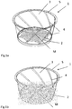
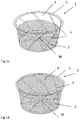
- FIGS. 1a to 1d the production of a container 1 is shown. It is shown schematically the relevant for the container 1 shaping by an injection mold, not shown.
- the cavity of the injection mold is designed to form the container 1 with a bottom 2 and a container wall 3.
- bead-like thickening 4 are provided in designated areas, which emerge from the Bode 2 and the container wall 3.
- the bottom 2 and the container wall 3 of the container 1 to be produced have a uniform thickness.
- the bead-like thickenings 4 are formed in a beam shape.
- the bead-like thickenings 4 on the container wall 3 extend from the bottom 2 with an obliquely oriented inclination to the upper edge 5 of the container 1 and are bent in one direction, wherein they have a radius of curvature which does not change its sign.
- a thickening is provided, on which a lid can be applied.
- the bead-like thickenings 4 have a constant and rounded cross-section. In the embodiment shown, the arrangement is axisymmetric to the vertical chosen by the center M of the bottom 2, so that a symmetrical container 1 is generated.
- FIG. 1a a first step of the injection molding process for the production of the container 1 is shown.
- Liquefied plastic or other material suitable for this process is injected into the cavity of the injection mold at a gate located at the midpoint M of the floor 2 and spreads axially symmetrically about the center M through the center.
- the bead-like thickenings 4 form flow aids. Due to the shape and arrangement of the flow aids, the flow front of the liquid plastic spreads uniformly and at a constant flow rate until the bottom 2, as in FIG. 1b shown, is covered in yellowish.
- the bottom 2 of the cup 1 has a uniform thickness in the areas between the thickenings 4 due to the uniform melt flow of the plastic.
- the liquid plastic rises uniformly and at a constant speed along the flow front by means of the flow aids on the container wall 3 up to the top 5, wherein the in Figure 1d shown container 1 is generated.
- the thickening at the top 5 is filled with plastic.
- the container wall 3 has in the areas between the bead-like thickenings 4 a constant uniform thickness.
- the bead-like thickenings 4 are selected depending on the product requirements. They may also be formed so that the bottom has a different thickness than the container wall.
- an insert element can be inserted in the container wall, which firmly in the production with the Kunststoffsoff and thus with the Container wall 3 is connected. Due to the uniform flow of the plastic, the insert element firmly adheres to the surface of the container wall 3 and is not covered with plastic.
- the present invention solves the problem by a special shape and orientation of the flow aids (also called supply beads), which are expressed in the container as ribs or bead-like thickening.
- the incipient overfeed of the plastic is guided over an optimized flow of the flow aids over the surfaces to be filled, so that mirror-like bead-like forms arise in the form of flow aids.
- the bead-like shapes are not or not exclusively aligned in the flow direction, but out as needed in sheet form or diagonal or depending on the size and necessity of maintaining the flowability with respect to the flow direction oblique layers around the shape of the container to be produced.
- the supply beads are introduced into the device, in particular in the injection molding tools. It does not matter for the container and its production, whether they are inside or outside. In this respect, the present invention differs significantly from that in the DE 20 46 958 B2 described solution in which the ribs must necessarily be positioned on the outside due to the required guarantee of mold release, because in the production always a shrinkage is taken into account; This shrinkage causes the rhomboids to virtually cling to the shape. Demoulding is not possible with non-destructive internal diamonds.
- the melt flow is deflected from the actual flow direction during production in such a way that the flowable plastic flows specifically through appropriately sized cross sections to the desired areas in which there is no corresponding support a premature solidification would take place.
- This technical solution means that the melt flows almost evenly into all, even the last to be filled, areas.
- the bead-like thickenings are applied in terms of size and desired or required wall thickness and depending on the desired thickness and shape of the upper cup end region, such as paths, so that during production the plastic is deflected from the actual flow direction in the respectively required manner.
- a container which has a particularly thin wall.
- the bead-like thickenings are on the inside.
- the bead-like thickenings do not intersect. They have a skew with respect to the cup wall.
- the cup can be demoulded by a rotational movement against the oblique direction of the ribs. If due to the arrangement of the bead-like thickening or due to the shape of the container demolding by a rotational movement is not or not completely possible, so may due to the small wall thickness and extensibility due to Residual heat in an immediate demolding after manufacture demolding completely or partially by a brief slipping over the device done.
- the invention can be applied in particular in the following areas: food containers, in particular cups for holding liquid or viscous, but also after solidification grouting food, if the food to be filled into the container are not plastic decomposition; other containers and cups or products, in particular for holding non-plastic decomposing liquid, viscous or such substances which solidify after filling in the liquid or viscous state, or containers for holding solid substances or products.
Landscapes
- Engineering & Computer Science (AREA)
- Mechanical Engineering (AREA)
- Ceramic Engineering (AREA)
- Manufacturing & Machinery (AREA)
- Containers Having Bodies Formed In One Piece (AREA)
- Injection Moulding Of Plastics Or The Like (AREA)
Description
Die Erfindung betrifft ein aus Kunststoff gespritztes Behältnis mit den Merkmalen des Oberbegriffs des Patentanspruchs 1.The invention relates to a plastic injection-molded container with the features of the preamble of
Becher sowie sonstige Behältnisse aus Kunststoff, werden herkömmlicherweise im Nachgang zur Herstellung des Produktes bedruckt, etikettiert und/oder gesleevt, also mit einem Schrumpfschlauch umhüllt.Cups and other containers made of plastic, are conventionally printed in subsequent to the production of the product, labeled and / or sleeved, so wrapped with a shrink tube.
Es ist aus der Praxis der
Ein Nachteil des IML-Verfahrens ist, dass der zur Verfügung stehende Querschnitt des Hohlraums durch das Einlegeteil ungünstig reduziert wird. Das Wandungsfließverhältnis, also das Verhältnis des längsten Fließweges zum mittleren Wandquerschitt, verschlechtert sich. Hierdurch kann es schneller zu einem vorzeitigen Erstarren der Schmelze kommen. Folge ist die erhöhte Gefahr einer nicht vollständigen Formfüllung. Um diesen Effekt auszugleichen und formschlüssige Behältnisse zu erhalten, ist es nach heutigem Stand erforderlich, eine dickere Wandstärke zu wählen. Dies führt zu einem erhöhten Materialeinsatz und größeren Gewicht der Becher. Höhere Kosten für Material und Transportkosten der produzierten Behältnisse sind die Folge.A disadvantage of the IML method is that the available cross section of the cavity is unfavorably reduced by the insert. The Wandungsfließverhältnis, ie the ratio of the longest flow path to the average Wandquerschitt, deteriorates. This can lead to premature solidification of the melt faster. The consequence is the increased risk of incomplete mold filling. Around To compensate for this effect and to obtain positive-locking containers, it is necessary today to choose a thicker wall thickness. This leads to an increased use of materials and greater weight of the cup. Higher costs for material and transport costs of the produced containers are the result.
Aus der
Aus der
Aus der
Aus der
Aus der
Aus der
Aus der
Es sind dünnwandige Becher bekannt, die im Wege des Thermoformverfahren, auch Extrusions-/Tiefziehverfahren genannt, hergestellt werden, bei dem ein Granulat zu Folien verarbeitet wird, aus denen dann die Verpackungsteile gezogen werden. Die Grenzen dieses Verfahrens liegen in der Formgenauigkeit und der Wandungsverteilung sowie Einschränkung möglicher Geometrien und Funktionen wie Stapelung der Produkte.Thin-walled cups are known, which are produced by means of the thermoforming method, also called extrusion / deep-drawing method, in which a granulate is processed into films, from which the packaging parts are then pulled. The limits of this method lie in the dimensional accuracy and the wall distribution and restriction of possible geometries and functions such as stacking of the products.
Eine andere Art von besonders dünnwandigen Behältnissen entsteht im Wege von Spritzgießverfahren oder Spritzgussverfahren. Bei diesem Spritzgießverfahren wird in der Regel Kunststoff-Granulat verflüssigt und mit hohem Druck in kürzest möglicher Zeit in einen Hohlraum gespritzt. In dem Hohlraum wird der Kunststoff abgekühlt. Durch das Abkühlen erstarrt der flüssige Kunststoff wieder. Beim Öffnen der Form kann die fertige Verpackung entnommen bzw. ausgeworfen werden.Another type of particularly thin-walled containers is produced by means of injection molding or injection molding. In this injection molding plastic granules is usually liquefied and injected at high pressure in the shortest possible time in a cavity. In the cavity of the plastic is cooled. By cooling, the liquid plastic solidifies again. When opening the mold, the finished packaging can be removed or ejected.
Vorteil des Spritzgießverfahrens ist die größere Genauigkeit sowie weitgehende Formfreiheit. Es können sehr viele unterschiedliche Geometrien produziert werden. Einzige Voraussetzung ist die Entformbarkeit der Teile, d.h. die Sicherstellung der Möglichkeit der Entnahme des produzierten Teiles aus der Form.Advantage of the injection molding is the greater accuracy and extensive freedom of form. Many different geometries can be produced. The only requirement is the demouldability of the parts, i. ensuring the possibility of removing the produced part from the mold.
Aus der
Bekannt sind Becher, die mit diversen unterschiedlich gearteten Fließhilfen, die in Fließrichtung ausgerichtet sind. Hierdurch wird der Schmelzefluss durch Fließhilfen in Fließrichtung erleichtert. Dadurch kommt es zu einer Verbesserung der Verfüllung, so dass dünnwandigere Becher hergestellt werden können. Die Fließhilfen bilden in dem Becher senkrecht nach oben führende wulstartige Verdickungen. Nachteil dieser Becher ist allerdings, dass bei der Produktion die Fließhilfen zu einem verstärkten Voreilen des Kunststoffes führen, was zu einer ungleichmäßigen Füllung der zuletzt zu füllenden Bereiche führt. Die Wandstärke der Becher wird ungleichmäßiger.Known are cups that are aligned with various types of flow aids, which are aligned in the flow direction. As a result, the melt flow is facilitated by flow aids in the flow direction. This results in an improvement of backfilling, so that thinner-walled cups can be produced. The flow aids form in the cup vertically upwardly bead-like thickening. Disadvantage of these cups, however, is that in the production of the flow aids lead to an increased lead of the plastic, resulting in an uneven filling of the last areas to be filled. The wall thickness of the cups becomes more uneven.
Auch führt das ungleichmäßige Verfüllen der zuletzt zu füllenden Bereiche bei einem IML-Verfahren dazu, dass der Kunststoff hinter oder vor die Einlegeteile fließt. Das führt zu einer unkontrollierten Überdeckung der Einlegeteile, was als Hinterspritzung bezeichnet wird. Der Vorlauf führt zu einer optischen Beeinträchtigung des Gesamteindrucks des Bechers. Bei Reduzierung der Wandstärke drohen zudem durch das Voreilen in den Fließhilfen Lufteinschlüsse, die zu einer fehlenden Formschlüssigkeit führen.Also, the uneven filling of the last areas to be filled in an IML process causes the plastic to flow behind or in front of the inserts. This leads to an uncontrolled overlap of the inserts, which is referred to as back injection. The flow leads to a visual impairment of the overall impression of the cup. When reducing the wall thickness also threaten by the lead in the flow aids air pockets, which lead to a lack of positive fit.
In der
Die Rippenstruktur des Bechers dieser Erfindung weist eine Rautenform auf. Werden die Rauten außenseitig angebracht, werden bei einem IML-Verfahren die anzubringenden Etiketten ebenfalls eine Rautenstruktur aufweisen. Dies führt zu einer schlechteren Lesbarkeit des Labels und Wahrnehmung des darauf dargestellten Inhalts des Behältnisses. Werden die Rippen innenseitig angebracht, ist eine Entnahme aus den Formen praktisch kaum möglich. Auch ist eine Rautenform auf der Innenseite von Bechern unerwünscht. Glatte Innenseiten ermöglichen eine vollständige Entnahmemöglichkeit des eingefüllten Füllgutes. Die Rautenform erschwert dagegen die Entnahme, da das Füllgut aus den Rauten zwischen den sich kreuzenden Rippen nur erschwert und im Zweifel nicht vollständig entnommen werden kann. Es besteht die Gefahr, dass das Füllgut nicht vollständig entnommen werden kann.The rib structure of the cup of this invention has a diamond shape. If the diamonds are attached to the outside, in an IML process the labels to be applied will also have a rhombic structure. This leads to a poorer readability of the label and perception of the contents of the container presented thereon. If the ribs are mounted on the inside, removal from the molds is virtually impossible. Also, a diamond shape on the inside of cups is undesirable. Smooth inner sides allow a complete removal of the filled contents. The diamond shape, however, makes it difficult to remove, since the contents of the diamonds between the intersecting ribs only complicates and in case of doubt can not be completely removed. There is a risk that the contents can not be completely removed.
Im Hinblick auf diesen Stand der Technik liegt der Erfindung die Aufgabe zugrunde, ein Behältnis zu schaffen, das nach dem IML-Verfahren hergestellt wird, dünnwandig und stabil ist, und auch im Etikettenbereich eine gleichmäßige und möglichst dünne Wandstärke aufweist.In view of this prior art, the present invention seeks to provide a container which is produced by the IML method, is thin-walled and stable, and also in the label area has a uniform and thin wall thickness as possible.
Diese Aufgabe wird durch ein Behältnis mit den Merkmalen des Patentanspruchs 1 gelöst.This object is achieved by a container having the features of
Bei dem erfindungsgemäßen Behältnis sind die wulstartigen Verdickungen so ausgebildet, dass sie sich auf der Behältniswand und am Boden nicht kreuzen, und jeweils einen Krümmungsradius mit konstantem Vorzeichen aufweisen. Sie haben somit einen Verlauf von Diagonalen oder in eine Richtung gebogenen Linien. Hierdurch wird erreicht, dass die Behältnisse mittels eines Spritzgussverfahrens mit einer sehr dünnen Behältniswand hergestellt werden können. Die wulstartigen Verdickungen entstehen entlang von in der Spritzgussform vorgesehen Fließhilfen, die entsprechend der Form der wulstartigen Verdickungen vorgesehen sind. Aufgrund der erfindungsgemäßen Form der Fließhilfen wird während des Produktionsprozesses eine gleichmäßige Fließfront des Kunststoffes gewährleistet. Hierdurch werden Lufteinschlüsse durch vorzeitiges Erstarren des Kunststoffes verhindert.In the container according to the invention, the bead-like thickenings are formed so that they do not intersect on the container wall and on the ground, and each having a radius of curvature with a constant sign. They thus have a course of diagonals or curved in one direction Lines. This ensures that the containers can be produced by means of an injection molding process with a very thin container wall. The bead-like thickenings arise along flow aids provided in the injection mold, which are provided according to the shape of the bead-like thickenings. Due to the inventive form of flow aids a uniform flow front of the plastic is ensured during the production process. As a result, air pockets are prevented by premature solidification of the plastic.
Durch diesen Verlauf der wulstartigen Verdickungen wird der Schmelzefluss so gelenkt, dass in den von vorzeitiger Erstarrung oder Abfrierungen bedrohten Bereichen der Schmelzefluss durch Querschnittsverstärkung und Erhalt der plastischen Seele vor vorzeitiger Erstarrung geschützt wird. Dies führt dazu, dass die Schmelzefront nahezu gleichmäßig in alle zu füllenden Bereiche fließt. Hierdurch wird eine gleichmäßige Füllung gewährleistet. Es wird dabei auch verhindert, dass geschmolzener Kunstsoff in den Bereichen der Fließhilfen vorauseilt und wieder nach unten läuft. Hierdurch wird einerseits unnötiges Material eingespart und andererseits verhindert, dass bei einem IML-Verfahren in den Bereichen, in denen ein Einlege-Element aufgebracht wird, das Einlege-Element mit herablaufendem Kunstsoff teilweise bedeckt wird oder dass aufgrund der Voreilung des flüssigen Kunststoffes die Einlege-Elemente hinterspritzt werden, da der Kunststoff unkontrolliert hinter das Einlege-Element fließt.Through this course of bead-like thickening of the melt flow is directed so that in the threatened by premature solidification or Abfrierungen areas of the melt flow is protected by cross-sectional reinforcement and preservation of the plastic soul from premature solidification. As a result, the melt front flows almost equally into all areas to be filled. This ensures a uniform filling. It is also prevented that molten Kunstsoff in the areas of flow aids leads ahead and runs down again. This saves on the one hand unnecessary material and on the other hand prevents that in an IML process in the areas in which an insert element is applied, the insert element is partially covered with runaway Kunstsoff or that due to the advance of the liquid plastic inserting Be injected behind elements as the plastic flows uncontrollably behind the insert element.
Aufgrund des erfindungsgemäßen Verlaufs der wulstartigen Verdickungen des Bechers wird auch ein einfaches Entformen des Bechers gewährleistet. Da die wulstartigen Verdickungen nur in eine Richtung gekrümmt sind, kann der Becher durch eine Drehbewegung leicht und ohne die Gefahr einer Beschädigung aus der Form entnommen werden. Hierdurch kann das Verfahren bis zum Schluss vollautomatisch durchgeführt werden, so dass das Verfahren vereinfacht wird und Kosten eingespart werden können. Auch die vollständige Entnahme eines Füllguts, mit dem das Behältnis bei Gebrauch gefüllt ist, wird durch die erfindungsgemäße Form der wulstartigen Verdickungen erleichtert.Due to the course according to the invention the bead-like thickening of the cup and a simple demolding of the cup is ensured. Since the bead-like thickenings are curved in one direction only, the cup can through a rotational movement can be easily removed without the risk of damage from the mold. As a result, the process can be carried out fully automatically until the end, so that the process is simplified and costs can be saved. Also, the complete removal of a filling material, with which the container is filled in use, is facilitated by the inventive shape of the bead-like thickening.
Gemäß der Erfindung ist ein Einlege-Element, insbesondere ein Papierstreifen, eine Kunststoffstreifen oder eine Folie, in einem Etikettenbereich auf der Außenseite der Behältniswand infolge des Spritzgussverfahrens fest mit dem Behältnis verbunden. Das Behältnis wurde mittels eines IML-Verfahrens hergestellt, bei dem das Einlege-Element in die Spritzgussform eingelegt wird, bevor der geschmolzene Kunststoff in die Spritzgussform eingespritzt wird. Hierbei ist der gleichmäßige Verlauf der Schmelzefront aufgrund der erfindungsgemäßen Anordnung der Fließhilfen und der wulstartigen Verdickungen besonders vorteilhaft, da die Einlege-Elemente auf einfache bei dem Herstellungsprozess mit dem Behältnis verbunden werden, ohne dass sie von Kunststoff bedeckt oder hinterlaufen werden. Es können somit vollständig lesbare Etiketten fest, glatt, zuverlässig und einfach auf das Behältnis aufgebracht werden.According to the invention, an insert element, in particular a paper strip, a plastic strip or a film, is firmly connected to the container in a label area on the outside of the container wall as a result of the injection molding process. The container was made by an IML process in which the insert element is inserted into the injection mold before the molten plastic is injected into the injection mold. Here, the uniform course of the melt front is particularly advantageous due to the inventive arrangement of flow aids and bead-like thickening, since the insert elements are connected to simple in the manufacturing process with the container without being covered or traced by plastic. Thus, fully readable labels can be fixed, smooth, reliable and easily applied to the container.
Vorteilhafte Ausführungsbeispiele der Erfindung sind in den Unteransprüchen offenbart.Advantageous embodiments of the invention are disclosed in the subclaims.
Gemäß einer vorteilhaften Weiterbildung der Erfindung ist die Neigung der wulstartigen Verdickungen auf der Behältniswand so gewählt, dass der Neigungswinkel N zum Boden etwa zwischen 30° und 60° beträgt. Hierdurch werden besonders gute Ergebnisse für eine Fließfront der Kunststoffschmelze mit konstanter Geschwindigkeit erzielt, so dass das Behältnis die gewünschte dünne, glatte, elastische und stabile Seitenwand aufweist. Es kann auch vorteilhaft sein, wenn der Krümmungsradius der wulstartigen Verdickungen zur Oberkante des Behältnisses hin zunimmt. Hierdurch kann die senkrechte und damit vorauseilende Komponente des flüssigen Kunststoffes gegen Ende des Prozesses weiter reduziert werden, wodurch eine noch gleichmäßigere und dünnere Behältniswand des Behältnisses erzielt werden kann. Es ist günstig, wenn die wulstartigen Verdickungen einen konstanten und zumindest teilweise gerundeten Querschnitt aufweisen. Der Querschnitt kann halbrund, rund oder auch oval ausgebildet sein. Hierdurch werden eine hohe Stabilität und ein leichtes Entformen gewährleistet.According to an advantageous embodiment of the invention, the inclination of the bead-like thickening on the container wall is chosen so that the inclination angle N to the ground is approximately between 30 ° and 60 °. This will be particularly good results achieved for a flow front of the plastic melt at a constant speed, so that the container has the desired thin, smooth, elastic and stable side wall. It may also be advantageous if the radius of curvature of the bead-like thickenings increases towards the upper edge of the container. As a result, the vertical and thus anticipatory component of the liquid plastic can be further reduced towards the end of the process, whereby a more uniform and thinner container wall of the container can be achieved. It is favorable if the bead-like thickenings have a constant and at least partially rounded cross-section. The cross section may be half-round, round or oval. This ensures high stability and easy demolding.
Gemäß einer vorteilhaften Weiterbildung der Erfindung sind von den wulstartigen Verdickungen ausgehende Abzweigungen vorgesehen, deren Länge und Querschnitt kleiner sind als die Länge und der Querschnitt der wulstartigen Verdickungen, wobei sich die Abzweigungen weder gegenseitig noch mit den Verdickungen kreuzen.According to an advantageous embodiment of the invention outgoing branches are provided by the bead-like thickening, the length and cross-section are smaller than the length and the cross section of the bead-like thickening, with the branches intersect neither mutually nor with the thickening.
Die Größe und Ausrichtung der durch die Fließhilfen entstehenden wulstartigen Verdickungen richtet sich je nach gewünschtem Produkt und Bedarf und bestimmt sich nach dem günstigsten Wandungsfließverhältnis und eingesetztem Material für das konkret zu produzierende Behältnis. Um gerade bei großflächigeren Produkten eine gleichmäßige Wandstärke zu gewährleisten, ist es des Weiteren im Einzelfall sinnvoll, ähnlich einem Adersystem des menschlichen Körpers die wulstartigen Verdickungen zu verzweigen bzw. kleinere oder gleich große Abzweigungen vorzusehen, die je nach Bedarf und Größe des zu spritzenden Produktes in beliebigem Winkel von dem jeweiligen Hauptstrang der jeweiligen Fließhilfe abzweigen. Hierdurch weist das Behältnis dann ein adernähnliches System von Verdickungen auf, je nach Wunsch an der Innenwand oder Außenwand des Behältnisses. Durch die hierdurch ermöglichte gleichmäßige Verteilung des Kunststoffs über den gesamten Bereich des Behältnisses wird zum einen sichergestellt, dass die gesamte Wand des Behältnisses mit Kunststoff verfüllt ist. Gleichzeitig wird eine Hinterspritzung möglicher Einlege-Elemente vermieden.The size and orientation of the resulting by the flow aids bead-like thickening depends on the desired product and needs and is determined by the most favorable Wandungsfließverhältnis and material used for the specific container to be produced. In order to ensure a uniform wall thickness, especially in larger-area products, it is further useful in individual cases, similar to a vein system of the human body to branch the bead-like thickening or provide smaller or equal branches, depending on need and size branch off the product to be sprayed at any angle from the respective main strand of the respective flow aid. As a result, the container then has a vein-like system of thickening, as desired on the inner wall or outer wall of the container. By thus allowing uniform distribution of the plastic over the entire area of the container is on the one hand ensures that the entire wall of the container is filled with plastic. At the same time a back injection of possible insert elements is avoided.
Vorteilhafterweise ist an der Oberkante des Behältnisses eine Verdickung vorgesehen, welche schlüssig zu der Behältniswand ausgebildet ist. Hierdurch ist ein stabiler Bereich des Behältnisses gewährleistet, auf welchen ein Deckel aufgebracht werden kann.Advantageously, a thickening is provided at the upper edge of the container, which is designed to be a good fit to the container wall. As a result, a stable region of the container is ensured on which a lid can be applied.
Gemäß einer vorteilhaften Ausgestaltung der Erfindung weist die Behältniswand einen ersten Bereich auf, in dem die wulstartigen Verdickungen einen größeren Querschnitt aufweisen als in dem zweiten Bereich, wodurch die Behältniswand in dem ersten Bereich eine größere Höhe aufweist als in dem zweiten Bereich. Gemäß einer anderen vorteilhaften Ausgestaltung der Erfindung weist die Behältniswand einen ersten Bereich auf, in dem die wulstartigen Verdickungen dichter beieinander liegen als in einem zweiten Bereich, wodurch die Behältniswand in dem ersten Bereich eine größere Höhe aufweist als in dem zweiten Bereich. Aufgrund der hier verwendeten Anordnung und Ausgestaltung der Fließhilfen wird während des Herstellungsprozesses in dem ersten Bereich der Behältniswand ein beschleunigtes Fließen und späteres Erstarren der Schmelzefront bewirkt. Hierdurch wird mehr Kunststoff in diese Bereiche verfüllt. Die längere Fließfähigkeit der Schmelzefront ermöglicht eine längere Becherwand. Es entsteht ein Behältnis mit unterschiedlichen Wandlängen bei dennoch vollständiger Füllung. Die wulstartigen Verdickungen auf den längeren Behälterflächen sind dicker ausgeprägt, auf den kürzeren Behälterflächen entsprechend dünner. Dabei wird gewährleistet, dass die Wandstärke - abgesehen von den wulstartigen Verdickungen - möglichst gleichmäßig und dünn sind.According to an advantageous embodiment of the invention, the container wall has a first region in which the bead-like thickenings have a larger cross-section than in the second region, whereby the container wall in the first region has a greater height than in the second region. According to another advantageous embodiment of the invention, the container wall has a first region in which the bead-like thickenings are closer together than in a second region, whereby the container wall in the first region has a greater height than in the second region. Due to the arrangement and design of the flow aids used here, an accelerated flow and later solidification of the melt front is effected during the manufacturing process in the first region of the container wall. As a result, more plastic is filled in these areas. The longer flowability of the melt front allows a longer cup wall. The result is a container with different wall lengths with complete filling. The bead-like thickening on the longer container surfaces are thicker, correspondingly thinner on the shorter container surfaces. This ensures that the wall thickness - apart from the bead-like thickening - as evenly as possible and thin.
Vorteilhafterweise können Behältnisse mit unterschiedlichen Kantenlängen des Einliege-Elements ausgebildet werden; denn durch unterschiedliche Ausprägungen der Fließhilfen ist es möglich, innerhalb der Form die Fließfront zur gleichen Zeit an allen Enden des Einlegers bereitzustellen. Dies ermöglicht Behältnisse mit entsprechend variablen Einlege-Elementen bei vollständiger Verfüllung.Advantageously, containers with different edge lengths of the inlay element can be formed; because of different forms of flow aids, it is possible to provide within the mold, the flow front at the same time at all ends of the insert. This allows containers with correspondingly variable insert elements with complete backfilling.
Gemäß der Erfindung kann das Behältnis auch ein anderes Material als Kunststoff umfassen, sofern sich das Material für die Verarbeitung in einem Spritzgießverfahren geeignet ist. Der genaue Verlauf der Fließhilfen, sowie deren Form, Querschnitt, Dichte, Anzahl, Form und Anzahl der Abzweigungen kann erfindungsgemäß dadurch optimiert werden, dass diese und ähnliche Größen rechnerisch für spezifische Produktanforderungen, wie die Größe des Behältnisses, die gewünschte oder erforderliche Wandstärke, gewünschte Stärke und Form des oberen Behältnisabschlusses bzw. der Verdickung an der Oberkante des Behältnisses etc., optimiert werden.According to the invention, the container may also comprise a material other than plastic, as long as the material is suitable for processing in an injection molding process. The exact course of the flow aids, as well as their shape, cross section, density, number, shape and number of branches can be optimized according to the invention, that these and similar sizes calculated for specific product requirements, such as the size of the container, the desired or required wall thickness desired Strength and shape of the upper container conclusion or the thickening at the upper edge of the container, etc., to be optimized.
Weitere Einzelheiten, Merkmale und Vorteile der vorliegenden Erfindung ergeben sich aus der nachfolgenden Beschreibung eines bevorzugten Ausführungsbeispiels unter Bezugnahme auf die Zeichnung.Further details, features and advantages of the present invention will become apparent from the following description of a preferred embodiment with reference to the drawings.
Es zeigen:
- Fig. 1a bis Fig. 1d
- Eine schematische Darstellung der Erzeugung eines Ausführungsbeispiels eines erfindungsgemäßen Behältnisses während des Produktionsverfahrens;
- Fig. 1a to Fig. 1d
- A schematic representation of the production of an embodiment of a container according to the invention during the production process;
In den
In
In dem Hohlraum der Spritzgussform kann ein Einlege-Element im Bereich der Behältniswand eingelegt werden, welches bei der Herstellung fest mit dem Kunstsoff und somit mit der Behältniswand 3 verbunden wird. Aufgrund des gleichmäßigen Flusses des Kunststoffes haftet das Einlege-Element fest auf der Oberfläche der Behältniswand 3 und ist nicht mit Kunststoff bedeckt.In the cavity of the injection mold, an insert element can be inserted in the container wall, which firmly in the production with the Kunstsoff and thus with the
Die hier vorliegende Erfindung löst das Problem durch eine besondere Formgebung und Ausrichtung der Fließhilfen (auch Versorgungswülste genannt), die sich in dem Behältnis als Rippen oder wulstartige Verdickungen ausprägen. Im Rahmen des Produktionsprozesses wird die beginnende Voreilung des Kunststoffes über einen optimierten Verlauf der Fließhilfen über die zu füllenden Flächen geführt, so dass spiegelbildlich wulstartige Ausprägungen entstehen in Form der Fließhilfen. Die wulstartigen Ausprägungen werden nicht oder nicht ausschließlich an der Fließrichtung ausgerichtet, sondern je nach Bedarf in Bogenform oder diagonalen bzw. je nach Größe und Erforderlichkeit der Aufrechterhaltung der Fließfähigkeit in Bezug auf die Fließrichtung schrägen Lagen rund um die Form des zu produzierenden Behältnisses geführt.The present invention solves the problem by a special shape and orientation of the flow aids (also called supply beads), which are expressed in the container as ribs or bead-like thickening. As part of the production process, the incipient overfeed of the plastic is guided over an optimized flow of the flow aids over the surfaces to be filled, so that mirror-like bead-like forms arise in the form of flow aids. The bead-like shapes are not or not exclusively aligned in the flow direction, but out as needed in sheet form or diagonal or depending on the size and necessity of maintaining the flowability with respect to the flow direction oblique layers around the shape of the container to be produced.
Die Versorgungswülste werden in der Vorrichtung, insbesondere in den Spritzgusswerkzeugen, eingebracht. Hierbei spielt es für das Behältnis und seine Produktion keine Rolle, ob diese innenseitig oder außenseitig angebracht sind. Insofern unterscheidet sich die hier vorliegende Erfindung deutlich von der in der
Durch den, je nach Produktanforderung bestimmbaren optimierten Verlauf der wulstartigen Verdickungen wird bei der Produktion der Schmelzefluss aus der eigentlichen Fließrichtung in solcher Weise abgelenkt, dass der fließfähige Kunststoff gezielt so lange durch entsprechend größenmäßig angepasste Querschnitte an die gewünschten Bereiche fließt, in denen ohne entsprechende Unterstützung ein vorzeitiges Erstarren erfolgen würde. Diese technische Lösung führt dazu, dass die Schmelze nahezu gleichmäßig in alle, auch die zuletzt zu füllenden, Bereiche fließt. Die wulstartigen Verdickungen werden je nach Produktanforderung hinsichtlich Größe und gewünschter bzw. erforderlicher Wandstärke und je nach gewünschter Stärke und Form des oberen Becherabschlussbereiches wie Pfade angelegt, so dass bei der Produktion der Kunststoff von der eigentlichen Strömungsrichtung in der jeweils erforderlichen Weise abgelenkt wird. Es entsteht ein Behältnis mit entsprechend schräg ausgerichteten wulstartigen Verdickungen bei gleichzeitig geringer Wandstärke. Diese Wandstärke wird durch die gezielte Ablenkung des Kunststoffs von der Fließrichtung möglichst gering gehalten mit Ausnahme der wulstartigen Verdickungen, die den technischen Erfordernissen im Rahmen des Herstellprozesses geschuldet sind.Due to the optimized course of the bead-like thickenings, which can be determined according to the product requirement, the melt flow is deflected from the actual flow direction during production in such a way that the flowable plastic flows specifically through appropriately sized cross sections to the desired areas in which there is no corresponding support a premature solidification would take place. This technical solution means that the melt flows almost evenly into all, even the last to be filled, areas. Depending on the product requirement, the bead-like thickenings are applied in terms of size and desired or required wall thickness and depending on the desired thickness and shape of the upper cup end region, such as paths, so that during production the plastic is deflected from the actual flow direction in the respectively required manner. The result is a container with corresponding obliquely oriented bead-like thickening at the same time low wall thickness. This wall thickness is kept as low as possible by the targeted deflection of the plastic from the flow direction with the exception of the bead-like thickening, which are due to the technical requirements in the context of the manufacturing process.
So wird ein Behältnis ermöglicht, das eine besonders dünne Wand aufweist. Die wulstartigen Verdickungen befinden sich auf der Innenseite. Die wulstartigen Verdickungen kreuzen sich nicht. Sie weisen eine Schräglage auf in Bezug auf die Becherwand. Der Becher lässt sich durch eine Drehbewegung entgegen der Schrägrichtung der Rippen entformen. Ist aufgrund der Anordnung der wulstartigen Verdickungen oder aufgrund der Form des Behältnisses eine Entformung durch eine Drehbewegung nicht oder nicht vollständig möglich, so kann aufgrund der geringen Wandstärke und Dehnbarkeit aufgrund der Restwärme bei einer unverzüglichen Entformung nach der Herstellung eine Entformung ganz oder zum Teil durch ein kurzfristiges Überstülpen über die Vorrichtung erfolgen.Thus, a container is made possible, which has a particularly thin wall. The bead-like thickenings are on the inside. The bead-like thickenings do not intersect. They have a skew with respect to the cup wall. The cup can be demoulded by a rotational movement against the oblique direction of the ribs. If due to the arrangement of the bead-like thickening or due to the shape of the container demolding by a rotational movement is not or not completely possible, so may due to the small wall thickness and extensibility due to Residual heat in an immediate demolding after manufacture demolding completely or partially by a brief slipping over the device done.
Anwendung finden kann die Erfindung insbesondere in folgenden Bereichen: Lebensmittelbehälter, insbesondere Becher für die Aufnahme flüssiger oder zähflüssiger, aber auch nach der Verfüllung sich verfestigender Lebensmittel, sofern die in den Behälter zu füllenden Lebensmittel nicht kunststoffzersetzend sind; sonstige Behälter und Becher oder Produkte, insbesondere für die Aufnahme von nicht Kunststoff zersetzenden flüssigen, zähflüssigen oder solchen Substanzen, die sich nach Verfüllung in flüssigem oder zähflüssigem Zustand verfestigen oder Behältnisse zur Aufnahme von festen Substanzen oder Produkten.The invention can be applied in particular in the following areas: food containers, in particular cups for holding liquid or viscous, but also after solidification grouting food, if the food to be filled into the container are not plastic decomposition; other containers and cups or products, in particular for holding non-plastic decomposing liquid, viscous or such substances which solidify after filling in the liquid or viscous state, or containers for holding solid substances or products.
Claims (11)
- Container (1) injection-moulded from plastic, comprising a bottom (2), a container wall (3) and an insert element, which is rigidly connected to the container in a label region on the outer side of the container wall (3), wherein the container (1) is produced by means of an IML process, characterized in that the bottom (2) and the container wall (3) have a uniform thickness, from which ridge-like thickenings (4) protrude inwards or outwards, starting from a gate mark in the bottom (2), having a radial course on the bottom (2) and extending on the container wall (3) with an obliquely oriented inclination towards the upper edge (5) of the container (1), wherein the ridge-like thickenings (4) on the container wall (3) and on the bottom (2) do not cross, in each case have a radius of curvature with a constant sign and are formed such that, as flow promoters, they ensure a uniform flow front of the plastic during the production process.
- Container according to Claim 1, characterized in that the ridge-like thickenings (4) are formed such that the flow front of the liquid plastic spreads out on the bottom (2) and on the container wall (3) at a constant rate in each case during the production process.
- Container according to one of the preceding claims, characterized in that the course and the cross section of the ridge-like thickenings are optimized for specific product requirements.
- Container according to one of the preceding claims, characterized in that the inclination of the ridge-like thickenings (4) on the container wall (3) is chosen such that the angle of inclination N in relation to the bottom (2) is approximately between 30° and 60°.
- Container according to one of the preceding claims, characterized in that the radius of curvature of the ridge-like thickenings (4) increases toward the upper edge (5) of the container (1).
- Container according to one of the preceding claims, characterized in that the ridge-like thickenings (4) have a constant and at least partially rounded cross section.
- Container according to one of the preceding claims, characterized in that branches starting from the ridge-like thickenings (4) and of a length and cross section smaller than the length and cross section of the ridge-like thickenings (4) are provided, wherein the branches do not cross one another or the thickenings.
- Container according to one of the preceding claims, characterized in that a thickening that is formed integrally with the container wall (3) is provided at the upper edge (5) of the container (1).
- Container according to one of the preceding claims, characterized in that the container wall (3) has a first region, in which the ridge-like thickenings (4) have a greater cross section than in a second region, whereby the container wall (3) has a greater height in the first region than in the second region.
- Container according to one of the preceding claims, characterized in that the container wall (3) has a first region, in which the ridge-like thickenings (4) are closer together than in a second region, whereby the container wall (3) has a greater height in the first region than in the second region.
- Container according to one of the preceding claims, characterized in that the insert element has differing edge lengths and the ridge-like thickenings are so pronounced that the flow front is provided at all ends of the insert element at the same time during production.
Applications Claiming Priority (2)
| Application Number | Priority Date | Filing Date | Title |
|---|---|---|---|
| DE102012103082.0A DE102012103082B4 (en) | 2012-04-11 | 2012-04-11 | Plastic injection-molded container made by an IML process |
| PCT/EP2013/057543 WO2013153142A1 (en) | 2012-04-11 | 2013-04-11 | Injection molded container made of plastic |
Publications (2)
| Publication Number | Publication Date |
|---|---|
| EP2836347A1 EP2836347A1 (en) | 2015-02-18 |
| EP2836347B1 true EP2836347B1 (en) | 2016-03-23 |
Family
ID=48184150
Family Applications (1)
| Application Number | Title | Priority Date | Filing Date |
|---|---|---|---|
| EP13718525.2A Not-in-force EP2836347B1 (en) | 2012-04-11 | 2013-04-11 | Injection moulded container made of plastic |
Country Status (9)
| Country | Link |
|---|---|
| US (1) | US20150060471A1 (en) |
| EP (1) | EP2836347B1 (en) |
| CA (1) | CA2869447C (en) |
| DE (1) | DE102012103082B4 (en) |
| DK (1) | DK2836347T3 (en) |
| ES (1) | ES2573836T3 (en) |
| HU (1) | HUE029251T2 (en) |
| PL (1) | PL2836347T3 (en) |
| WO (1) | WO2013153142A1 (en) |
Families Citing this family (6)
| Publication number | Priority date | Publication date | Assignee | Title |
|---|---|---|---|---|
| US20140312032A1 (en) * | 2013-04-22 | 2014-10-23 | Steven Davidian | Containers |
| DE102015102097A1 (en) | 2015-02-13 | 2016-08-18 | Knauer Holding Gmbh & Co. Kg | Method for producing a plastic container according to an IML method, container and label element |
| GB2538051A (en) * | 2015-04-27 | 2016-11-09 | John Michael Jurkiw Anthony | A mould |
| FR3093664B1 (en) * | 2019-03-11 | 2022-01-21 | Europlastiques | Method of manufacturing by molding a container having at least one double-curved surface on which a label is applied. |
| US12012250B2 (en) * | 2019-06-07 | 2024-06-18 | Glenn H. Morris, Jr. | Container with sidewall pillars |
| DE102021112867A1 (en) | 2020-07-08 | 2022-01-13 | Orga.nico GmbH & Co. KG | Container and injection molding device |
Citations (7)
| Publication number | Priority date | Publication date | Assignee | Title |
|---|---|---|---|---|
| DE2046958A1 (en) | 1970-06-01 | 1971-12-16 | Conlor Molding Systems Ltd | Injection molded cup-shaped object |
| DE2652172A1 (en) | 1976-11-16 | 1978-05-24 | Erich Blattert | PROCESS FOR MANUFACTURING A HOLLOW BODY INJECTED FROM PLASTIC, THICK FILM AND HOLLOW BODY MANUFACTURED BY THIS PROCESS |
| JP2000281038A (en) | 1999-04-01 | 2000-10-10 | Dainippon Printing Co Ltd | In-mold label container with rib |
| JP2006001569A (en) | 2004-06-16 | 2006-01-05 | Fuji Seal International Inc | Container |
| EP1757525A1 (en) | 2004-05-19 | 2007-02-28 | K.M Planning Co., Ltd. | In-mold label container with rib and method of manufacturing the same |
| JP2008137680A (en) | 2006-11-30 | 2008-06-19 | Yoshino Kogyosho Co Ltd | Synthetic resin cup-shaped container |
| JP2011031937A (en) | 2009-07-31 | 2011-02-17 | Yoshino Kogyosho Co Ltd | Cup-like container with in-mold label |
Family Cites Families (20)
| Publication number | Priority date | Publication date | Assignee | Title |
|---|---|---|---|---|
| DE7225262U (en) * | 1972-11-02 | Blattert E | Hollow bodies injection-molded from plastic, such as flower pots, cups or the like | |
| DE7227210U (en) * | 1972-10-26 | Schmalbach-Lubeca-Werke Ag | Plastic container open at one end | |
| GB1038897A (en) * | 1964-03-12 | 1966-08-10 | Metal Box Co Ltd | Improvements in or relating to plastics containers |
| CH540822A (en) * | 1971-07-28 | 1973-08-31 | Schmalbach Lubeca | Plastic container open at one end |
| DE2614213A1 (en) * | 1976-04-02 | 1977-10-20 | Ver Foerderung Inst Kunststoff | Injection-moulding of thick-walled, large-volume mouldings - by effecting successive pressure impulses during a post-pressure phase, on the compressible moulding cpd. in the mould |
| US4170622A (en) * | 1977-05-26 | 1979-10-09 | Owens-Illinois, Inc. | Method of making a blown hollow article having a ribbed interior surface |
| DE2855501C2 (en) * | 1978-12-22 | 1984-04-12 | Erich 7141 Steinheim Blattert | Plastic injection molded container |
| JPS56156711U (en) * | 1980-04-21 | 1981-11-21 | ||
| US4997692A (en) * | 1982-01-29 | 1991-03-05 | Yoshino Kogyosho Co., Ltd. | Synthetic resin made thin-walled bottle |
| US5149482A (en) * | 1989-06-05 | 1992-09-22 | Primtec | Injection-molding dimension-control and clamp-reduction |
| JP2868281B2 (en) * | 1990-05-07 | 1999-03-10 | 雪印乳業株式会社 | Container with in-mold labeling on outer surface of curved side wall and method of manufacturing the same |
| JPH08197599A (en) * | 1995-01-25 | 1996-08-06 | Sekisui Chem Co Ltd | Production of thin-walled molded product |
| US5582957A (en) * | 1995-03-28 | 1996-12-10 | Eastman Kodak Company | Resuspension optimization for photographic nanosuspensions |
| US20040031802A1 (en) * | 2002-08-13 | 2004-02-19 | Parodi Donald E. | Container having internal strengthening ribs |
| JP3732832B2 (en) * | 2003-01-27 | 2006-01-11 | 株式会社日本製鋼所 | Synthetic resin hollow body injection molding method and molding die |
| JP4527056B2 (en) * | 2003-06-19 | 2010-08-18 | 大日本印刷株式会社 | In-mold label type plastic container |
| USD490017S1 (en) * | 2003-10-08 | 2004-05-18 | Kenneth A. Harbaugh | Planter |
| DE102005045621A1 (en) * | 2005-09-23 | 2007-04-05 | Abro Weidenhammer Gmbh | Producing packaging containers by plasticating and injection molding a plastic material comprises introducing a gastight film into the mold before injecting the plastic material |
| NL1031430C2 (en) * | 2006-03-23 | 2007-09-25 | Rpc Bebo Nederland | Food packaging tub. |
| CA2631762A1 (en) * | 2008-05-14 | 2009-11-14 | Stackteck Systems Limited | Reduced thickness injection moulded part design |
-
2012
- 2012-04-11 DE DE102012103082.0A patent/DE102012103082B4/en not_active Expired - Fee Related
-
2013
- 2013-04-11 DK DK13718525.2T patent/DK2836347T3/en active
- 2013-04-11 ES ES13718525.2T patent/ES2573836T3/en active Active
- 2013-04-11 EP EP13718525.2A patent/EP2836347B1/en not_active Not-in-force
- 2013-04-11 PL PL13718525.2T patent/PL2836347T3/en unknown
- 2013-04-11 US US14/391,751 patent/US20150060471A1/en not_active Abandoned
- 2013-04-11 WO PCT/EP2013/057543 patent/WO2013153142A1/en active Application Filing
- 2013-04-11 HU HUE13718525A patent/HUE029251T2/en unknown
- 2013-04-11 CA CA2869447A patent/CA2869447C/en not_active Expired - Fee Related
Patent Citations (7)
| Publication number | Priority date | Publication date | Assignee | Title |
|---|---|---|---|---|
| DE2046958A1 (en) | 1970-06-01 | 1971-12-16 | Conlor Molding Systems Ltd | Injection molded cup-shaped object |
| DE2652172A1 (en) | 1976-11-16 | 1978-05-24 | Erich Blattert | PROCESS FOR MANUFACTURING A HOLLOW BODY INJECTED FROM PLASTIC, THICK FILM AND HOLLOW BODY MANUFACTURED BY THIS PROCESS |
| JP2000281038A (en) | 1999-04-01 | 2000-10-10 | Dainippon Printing Co Ltd | In-mold label container with rib |
| EP1757525A1 (en) | 2004-05-19 | 2007-02-28 | K.M Planning Co., Ltd. | In-mold label container with rib and method of manufacturing the same |
| JP2006001569A (en) | 2004-06-16 | 2006-01-05 | Fuji Seal International Inc | Container |
| JP2008137680A (en) | 2006-11-30 | 2008-06-19 | Yoshino Kogyosho Co Ltd | Synthetic resin cup-shaped container |
| JP2011031937A (en) | 2009-07-31 | 2011-02-17 | Yoshino Kogyosho Co Ltd | Cup-like container with in-mold label |
Also Published As
| Publication number | Publication date |
|---|---|
| PL2836347T3 (en) | 2016-09-30 |
| WO2013153142A1 (en) | 2013-10-17 |
| EP2836347A1 (en) | 2015-02-18 |
| US20150060471A1 (en) | 2015-03-05 |
| ES2573836T3 (en) | 2016-06-10 |
| HUE029251T2 (en) | 2017-02-28 |
| DE102012103082B4 (en) | 2014-11-27 |
| CA2869447C (en) | 2016-10-11 |
| DE102012103082A1 (en) | 2013-10-17 |
| CA2869447A1 (en) | 2013-10-17 |
| DK2836347T3 (en) | 2016-06-27 |
Similar Documents
| Publication | Publication Date | Title |
|---|---|---|
| EP2836347B1 (en) | Injection moulded container made of plastic | |
| EP1058626B1 (en) | Fuel tank with integrated heat shield | |
| DE60010070T2 (en) | METHOD FOR PRODUCING LAMINATED BOTTLES WITH A PEELABLE INNER LAYER | |
| EP1938944B1 (en) | Method for producing a multi-layered plastic body | |
| EP1465759B1 (en) | Method and device of the production of brushes | |
| DE2916380A1 (en) | DEVICE FOR REMOVING AN INJECTION MOLDED PART FROM AN INJECTION MOLD | |
| EP0113642B1 (en) | Closure cap for a container and method for its manufacture | |
| DE9210022U1 (en) | Thin-walled plastic bottle with structured surface | |
| DE2123472A1 (en) | Containers made using injection molding and methods for making them | |
| DE202010008758U1 (en) | Injection mold for flexible tube | |
| EP2934846B1 (en) | Process for manufacturing a plastic article and an injection moulding apparatus | |
| DE10105699A1 (en) | Method and device for producing a diffusion-tight plastic container | |
| EP3988272B1 (en) | Method of producing a composite body by means of injection moulding | |
| DE69627824T2 (en) | METHOD AND DEVICE FOR PRODUCING TUBULAR CONTAINERS WITH LOCKING DEVICE | |
| DE3434366A1 (en) | Mould for producing mouldings by backfilling film shells with a plastics moulding compound | |
| EP2483049B1 (en) | Imd mold, injection molding apparatus having such an imd mold and method for producing a foil-decorated plastic part | |
| DE102016225928A1 (en) | Injection molding tool for producing a molded part by injection molding a film, and injection molding tool system with such an injection molding tool | |
| EP4132315B1 (en) | Fastener part | |
| EP2601026B1 (en) | Process and device for producing plastic parisons for large-volume containers | |
| DE2705548A1 (en) | METHOD OF REINFORCEMENT OF A THERMOFORMED PART AND DEVICE FOR CARRYING OUT THE METHOD | |
| EP0619174A1 (en) | Process for making thermoplastic hollow objects | |
| EP2633968B1 (en) | Method for producing a plastic container and plastic container | |
| EP3131730B1 (en) | Method for transferring bottom labels and wraparound labels into an injection mould and device, suitable for this purpose, for producing injection-moulded parts provided with bottom labels and wraparound labels | |
| WO2016128521A1 (en) | Method for producing a container from plastic, container, and label element | |
| DE102014222984B4 (en) | Method and tool for producing a wheel carrier and wheel carrier |
Legal Events
| Date | Code | Title | Description |
|---|---|---|---|
| PUAI | Public reference made under article 153(3) epc to a published international application that has entered the european phase |
Free format text: ORIGINAL CODE: 0009012 |
|
| 17P | Request for examination filed |
Effective date: 20141001 |
|
| AK | Designated contracting states |
Kind code of ref document: A1 Designated state(s): AL AT BE BG CH CY CZ DE DK EE ES FI FR GB GR HR HU IE IS IT LI LT LU LV MC MK MT NL NO PL PT RO RS SE SI SK SM TR |
|
| AX | Request for extension of the european patent |
Extension state: BA ME |
|
| R17P | Request for examination filed (corrected) |
Effective date: 20141001 |
|
| RBV | Designated contracting states (corrected) |
Designated state(s): AL AT BE BG CH CY CZ DE DK EE ES FI FR GB GR HR HU IE IS IT LI LT LU LV MC MK MT NL NO PL PT RO RS SE SI SK SM TR |
|
| 17Q | First examination report despatched |
Effective date: 20150603 |
|
| DAX | Request for extension of the european patent (deleted) | ||
| GRAP | Despatch of communication of intention to grant a patent |
Free format text: ORIGINAL CODE: EPIDOSNIGR1 |
|
| INTG | Intention to grant announced |
Effective date: 20151007 |
|
| GRAS | Grant fee paid |
Free format text: ORIGINAL CODE: EPIDOSNIGR3 |
|
| GRAA | (expected) grant |
Free format text: ORIGINAL CODE: 0009210 |
|
| AK | Designated contracting states |
Kind code of ref document: B1 Designated state(s): AL AT BE BG CH CY CZ DE DK EE ES FI FR GB GR HR HU IE IS IT LI LT LU LV MC MK MT NL NO PL PT RO RS SE SI SK SM TR |
|
| REG | Reference to a national code |
Ref country code: GB Ref legal event code: FG4D Free format text: NOT ENGLISH |
|
| REG | Reference to a national code |
Ref country code: CH Ref legal event code: EP |
|
| REG | Reference to a national code |
Ref country code: AT Ref legal event code: REF Ref document number: 782679 Country of ref document: AT Kind code of ref document: T Effective date: 20160415 Ref country code: CH Ref legal event code: NV Representative=s name: INDUSTRIAL PROPERTY SERVICES GMBH, CH |
|
| REG | Reference to a national code |
Ref country code: IE Ref legal event code: FG4D Free format text: LANGUAGE OF EP DOCUMENT: GERMAN |
|
| REG | Reference to a national code |
Ref country code: FR Ref legal event code: PLFP Year of fee payment: 4 |
|
| REG | Reference to a national code |
Ref country code: DE Ref legal event code: R096 Ref document number: 502013002297 Country of ref document: DE |
|
| REG | Reference to a national code |
Ref country code: ES Ref legal event code: FG2A Ref document number: 2573836 Country of ref document: ES Kind code of ref document: T3 Effective date: 20160610 |
|
| REG | Reference to a national code |
Ref country code: DK Ref legal event code: T3 Effective date: 20160623 |
|
| REG | Reference to a national code |
Ref country code: SE Ref legal event code: TRGR |
|
| REG | Reference to a national code |
Ref country code: NL Ref legal event code: FP |
|
| REG | Reference to a national code |
Ref country code: LT Ref legal event code: MG4D |
|
| PG25 | Lapsed in a contracting state [announced via postgrant information from national office to epo] |
Ref country code: HR Free format text: LAPSE BECAUSE OF FAILURE TO SUBMIT A TRANSLATION OF THE DESCRIPTION OR TO PAY THE FEE WITHIN THE PRESCRIBED TIME-LIMIT Effective date: 20160323 Ref country code: GR Free format text: LAPSE BECAUSE OF FAILURE TO SUBMIT A TRANSLATION OF THE DESCRIPTION OR TO PAY THE FEE WITHIN THE PRESCRIBED TIME-LIMIT Effective date: 20160624 |
|
| REG | Reference to a national code |
Ref country code: NO Ref legal event code: T2 Effective date: 20160323 |
|
| PG25 | Lapsed in a contracting state [announced via postgrant information from national office to epo] |
Ref country code: LT Free format text: LAPSE BECAUSE OF FAILURE TO SUBMIT A TRANSLATION OF THE DESCRIPTION OR TO PAY THE FEE WITHIN THE PRESCRIBED TIME-LIMIT Effective date: 20160323 Ref country code: RS Free format text: LAPSE BECAUSE OF FAILURE TO SUBMIT A TRANSLATION OF THE DESCRIPTION OR TO PAY THE FEE WITHIN THE PRESCRIBED TIME-LIMIT Effective date: 20160323 Ref country code: LV Free format text: LAPSE BECAUSE OF FAILURE TO SUBMIT A TRANSLATION OF THE DESCRIPTION OR TO PAY THE FEE WITHIN THE PRESCRIBED TIME-LIMIT Effective date: 20160323 |
|
| PG25 | Lapsed in a contracting state [announced via postgrant information from national office to epo] |
Ref country code: EE Free format text: LAPSE BECAUSE OF FAILURE TO SUBMIT A TRANSLATION OF THE DESCRIPTION OR TO PAY THE FEE WITHIN THE PRESCRIBED TIME-LIMIT Effective date: 20160323 Ref country code: IS Free format text: LAPSE BECAUSE OF FAILURE TO SUBMIT A TRANSLATION OF THE DESCRIPTION OR TO PAY THE FEE WITHIN THE PRESCRIBED TIME-LIMIT Effective date: 20160723 |
|
| PG25 | Lapsed in a contracting state [announced via postgrant information from national office to epo] |
Ref country code: SM Free format text: LAPSE BECAUSE OF FAILURE TO SUBMIT A TRANSLATION OF THE DESCRIPTION OR TO PAY THE FEE WITHIN THE PRESCRIBED TIME-LIMIT Effective date: 20160323 Ref country code: SK Free format text: LAPSE BECAUSE OF FAILURE TO SUBMIT A TRANSLATION OF THE DESCRIPTION OR TO PAY THE FEE WITHIN THE PRESCRIBED TIME-LIMIT Effective date: 20160323 Ref country code: RO Free format text: LAPSE BECAUSE OF FAILURE TO SUBMIT A TRANSLATION OF THE DESCRIPTION OR TO PAY THE FEE WITHIN THE PRESCRIBED TIME-LIMIT Effective date: 20160323 Ref country code: PT Free format text: LAPSE BECAUSE OF FAILURE TO SUBMIT A TRANSLATION OF THE DESCRIPTION OR TO PAY THE FEE WITHIN THE PRESCRIBED TIME-LIMIT Effective date: 20160725 |
|
| REG | Reference to a national code |
Ref country code: DE Ref legal event code: R026 Ref document number: 502013002297 Country of ref document: DE |
|
| PLBI | Opposition filed |
Free format text: ORIGINAL CODE: 0009260 |
|
| RAP2 | Party data changed (patent owner data changed or rights of a patent transferred) |
Owner name: KNAUER HOLDING GMBH & CO. KG |
|
| 26 | Opposition filed |
Opponent name: RUNDPACK AG Effective date: 20161215 |
|
| REG | Reference to a national code |
Ref country code: IE Ref legal event code: MM4A |
|
| PLAX | Notice of opposition and request to file observation + time limit sent |
Free format text: ORIGINAL CODE: EPIDOSNOBS2 |
|
| PG25 | Lapsed in a contracting state [announced via postgrant information from national office to epo] |
Ref country code: BG Free format text: LAPSE BECAUSE OF FAILURE TO SUBMIT A TRANSLATION OF THE DESCRIPTION OR TO PAY THE FEE WITHIN THE PRESCRIBED TIME-LIMIT Effective date: 20160623 |
|
| REG | Reference to a national code |
Ref country code: HU Ref legal event code: AG4A Ref document number: E029251 Country of ref document: HU |
|
| REG | Reference to a national code |
Ref country code: FR Ref legal event code: PLFP Year of fee payment: 5 |
|
| PLAF | Information modified related to communication of a notice of opposition and request to file observations + time limit |
Free format text: ORIGINAL CODE: EPIDOSCOBS2 |
|
| PG25 | Lapsed in a contracting state [announced via postgrant information from national office to epo] |
Ref country code: IE Free format text: LAPSE BECAUSE OF NON-PAYMENT OF DUE FEES Effective date: 20160411 Ref country code: SI Free format text: LAPSE BECAUSE OF FAILURE TO SUBMIT A TRANSLATION OF THE DESCRIPTION OR TO PAY THE FEE WITHIN THE PRESCRIBED TIME-LIMIT Effective date: 20160323 |
|
| PLBB | Reply of patent proprietor to notice(s) of opposition received |
Free format text: ORIGINAL CODE: EPIDOSNOBS3 |
|
| PLBD | Termination of opposition procedure: decision despatched |
Free format text: ORIGINAL CODE: EPIDOSNOPC1 |
|
| PLAB | Opposition data, opponent's data or that of the opponent's representative modified |
Free format text: ORIGINAL CODE: 0009299OPPO |
|
| PLBP | Opposition withdrawn |
Free format text: ORIGINAL CODE: 0009264 |
|
| RAP2 | Party data changed (patent owner data changed or rights of a patent transferred) |
Owner name: VVA VERPACKUNG VERTRIEBS- UND ABSATZ AG |
|
| REG | Reference to a national code |
Ref country code: DE Ref legal event code: R100 Ref document number: 502013002297 Country of ref document: DE |
|
| PLBM | Termination of opposition procedure: date of legal effect published |
Free format text: ORIGINAL CODE: 0009276 |
|
| STAA | Information on the status of an ep patent application or granted ep patent |
Free format text: STATUS: OPPOSITION PROCEDURE CLOSED |
|
| 27C | Opposition proceedings terminated |
Effective date: 20170817 |
|
| REG | Reference to a national code |
Ref country code: FR Ref legal event code: PLFP Year of fee payment: 6 |
|
| PG25 | Lapsed in a contracting state [announced via postgrant information from national office to epo] |
Ref country code: MK Free format text: LAPSE BECAUSE OF FAILURE TO SUBMIT A TRANSLATION OF THE DESCRIPTION OR TO PAY THE FEE WITHIN THE PRESCRIBED TIME-LIMIT Effective date: 20160323 Ref country code: CY Free format text: LAPSE BECAUSE OF FAILURE TO SUBMIT A TRANSLATION OF THE DESCRIPTION OR TO PAY THE FEE WITHIN THE PRESCRIBED TIME-LIMIT Effective date: 20160323 Ref country code: LU Free format text: LAPSE BECAUSE OF NON-PAYMENT OF DUE FEES Effective date: 20160411 Ref country code: MC Free format text: LAPSE BECAUSE OF FAILURE TO SUBMIT A TRANSLATION OF THE DESCRIPTION OR TO PAY THE FEE WITHIN THE PRESCRIBED TIME-LIMIT Effective date: 20160323 Ref country code: MT Free format text: LAPSE BECAUSE OF FAILURE TO SUBMIT A TRANSLATION OF THE DESCRIPTION OR TO PAY THE FEE WITHIN THE PRESCRIBED TIME-LIMIT Effective date: 20160323 |
|
| PGFP | Annual fee paid to national office [announced via postgrant information from national office to epo] |
Ref country code: NL Payment date: 20180423 Year of fee payment: 6 |
|
| PGFP | Annual fee paid to national office [announced via postgrant information from national office to epo] |
Ref country code: DE Payment date: 20180423 Year of fee payment: 6 Ref country code: FI Payment date: 20180418 Year of fee payment: 6 Ref country code: ES Payment date: 20180523 Year of fee payment: 6 Ref country code: DK Payment date: 20180424 Year of fee payment: 6 Ref country code: CZ Payment date: 20180403 Year of fee payment: 6 Ref country code: NO Payment date: 20180420 Year of fee payment: 6 Ref country code: CH Payment date: 20180424 Year of fee payment: 6 |
|
| PGFP | Annual fee paid to national office [announced via postgrant information from national office to epo] |
Ref country code: BE Payment date: 20180423 Year of fee payment: 6 Ref country code: AT Payment date: 20180418 Year of fee payment: 6 Ref country code: PL Payment date: 20180405 Year of fee payment: 6 Ref country code: FR Payment date: 20180424 Year of fee payment: 6 Ref country code: IT Payment date: 20180420 Year of fee payment: 6 |
|
| PGFP | Annual fee paid to national office [announced via postgrant information from national office to epo] |
Ref country code: SE Payment date: 20180424 Year of fee payment: 6 Ref country code: HU Payment date: 20180403 Year of fee payment: 6 |
|
| PG25 | Lapsed in a contracting state [announced via postgrant information from national office to epo] |
Ref country code: TR Free format text: LAPSE BECAUSE OF FAILURE TO SUBMIT A TRANSLATION OF THE DESCRIPTION OR TO PAY THE FEE WITHIN THE PRESCRIBED TIME-LIMIT Effective date: 20160323 Ref country code: AL Free format text: LAPSE BECAUSE OF FAILURE TO SUBMIT A TRANSLATION OF THE DESCRIPTION OR TO PAY THE FEE WITHIN THE PRESCRIBED TIME-LIMIT Effective date: 20160323 |
|
| PGFP | Annual fee paid to national office [announced via postgrant information from national office to epo] |
Ref country code: GB Payment date: 20180424 Year of fee payment: 6 |
|
| REG | Reference to a national code |
Ref country code: DE Ref legal event code: R119 Ref document number: 502013002297 Country of ref document: DE |
|
| REG | Reference to a national code |
Ref country code: NO Ref legal event code: MMEP |
|
| REG | Reference to a national code |
Ref country code: CH Ref legal event code: PL |
|
| REG | Reference to a national code |
Ref country code: DK Ref legal event code: EBP Effective date: 20190430 |
|
| REG | Reference to a national code |
Ref country code: SE Ref legal event code: EUG |
|
| REG | Reference to a national code |
Ref country code: NL Ref legal event code: MM Effective date: 20190501 |
|
| REG | Reference to a national code |
Ref country code: AT Ref legal event code: MM01 Ref document number: 782679 Country of ref document: AT Kind code of ref document: T Effective date: 20190411 |
|
| REG | Reference to a national code |
Ref country code: BE Ref legal event code: MM Effective date: 20190430 |
|
| GBPC | Gb: european patent ceased through non-payment of renewal fee |
Effective date: 20190411 |
|
| PG25 | Lapsed in a contracting state [announced via postgrant information from national office to epo] |
Ref country code: AT Free format text: LAPSE BECAUSE OF NON-PAYMENT OF DUE FEES Effective date: 20190411 Ref country code: HU Free format text: LAPSE BECAUSE OF NON-PAYMENT OF DUE FEES Effective date: 20190412 Ref country code: NL Free format text: LAPSE BECAUSE OF NON-PAYMENT OF DUE FEES Effective date: 20190501 Ref country code: NO Free format text: LAPSE BECAUSE OF NON-PAYMENT OF DUE FEES Effective date: 20190430 Ref country code: DE Free format text: LAPSE BECAUSE OF NON-PAYMENT OF DUE FEES Effective date: 20191101 Ref country code: CH Free format text: LAPSE BECAUSE OF NON-PAYMENT OF DUE FEES Effective date: 20190430 Ref country code: FI Free format text: LAPSE BECAUSE OF NON-PAYMENT OF DUE FEES Effective date: 20190411 Ref country code: CZ Free format text: LAPSE BECAUSE OF NON-PAYMENT OF DUE FEES Effective date: 20190411 Ref country code: LI Free format text: LAPSE BECAUSE OF NON-PAYMENT OF DUE FEES Effective date: 20190430 Ref country code: SE Free format text: LAPSE BECAUSE OF NON-PAYMENT OF DUE FEES Effective date: 20190412 Ref country code: GB Free format text: LAPSE BECAUSE OF NON-PAYMENT OF DUE FEES Effective date: 20190411 |
|
| PG25 | Lapsed in a contracting state [announced via postgrant information from national office to epo] |
Ref country code: FR Free format text: LAPSE BECAUSE OF NON-PAYMENT OF DUE FEES Effective date: 20190430 Ref country code: BE Free format text: LAPSE BECAUSE OF NON-PAYMENT OF DUE FEES Effective date: 20190430 |
|
| PG25 | Lapsed in a contracting state [announced via postgrant information from national office to epo] |
Ref country code: IT Free format text: LAPSE BECAUSE OF NON-PAYMENT OF DUE FEES Effective date: 20190411 Ref country code: DK Free format text: LAPSE BECAUSE OF NON-PAYMENT OF DUE FEES Effective date: 20190430 |
|
| REG | Reference to a national code |
Ref country code: ES Ref legal event code: FD2A Effective date: 20200828 |
|
| PG25 | Lapsed in a contracting state [announced via postgrant information from national office to epo] |
Ref country code: ES Free format text: LAPSE BECAUSE OF NON-PAYMENT OF DUE FEES Effective date: 20190412 |
|
| PG25 | Lapsed in a contracting state [announced via postgrant information from national office to epo] |
Ref country code: PL Free format text: LAPSE BECAUSE OF NON-PAYMENT OF DUE FEES Effective date: 20190411 |