DE102020007585A1 - locking part - Google Patents
locking part Download PDFInfo
- Publication number
- DE102020007585A1 DE102020007585A1 DE102020007585.1A DE102020007585A DE102020007585A1 DE 102020007585 A1 DE102020007585 A1 DE 102020007585A1 DE 102020007585 A DE102020007585 A DE 102020007585A DE 102020007585 A1 DE102020007585 A1 DE 102020007585A1
- Authority
- DE
- Germany
- Prior art keywords
- closure
- crater
- head
- depression
- carrier part
- Prior art date
- Legal status (The legal status is an assumption and is not a legal conclusion. Google has not performed a legal analysis and makes no representation as to the accuracy of the status listed.)
- Pending
Links
Images


Classifications
-
- A—HUMAN NECESSITIES
- A44—HABERDASHERY; JEWELLERY
- A44B—BUTTONS, PINS, BUCKLES, SLIDE FASTENERS, OR THE LIKE
- A44B18/00—Fasteners of the touch-and-close type; Making such fasteners
- A44B18/0046—Fasteners made integrally of plastics
- A44B18/0049—Fasteners made integrally of plastics obtained by moulding processes
-
- A—HUMAN NECESSITIES
- A44—HABERDASHERY; JEWELLERY
- A44B—BUTTONS, PINS, BUCKLES, SLIDE FASTENERS, OR THE LIKE
- A44B18/00—Fasteners of the touch-and-close type; Making such fasteners
- A44B18/0003—Fastener constructions
- A44B18/0015—Male or hook elements
- A44B18/0019—Male or hook elements of a mushroom type
-
- A—HUMAN NECESSITIES
- A44—HABERDASHERY; JEWELLERY
- A44B—BUTTONS, PINS, BUCKLES, SLIDE FASTENERS, OR THE LIKE
- A44B18/00—Fasteners of the touch-and-close type; Making such fasteners
- A44B18/0046—Fasteners made integrally of plastics
- A44B18/0061—Male or hook elements
- A44B18/0065—Male or hook elements of a mushroom type
-
- B—PERFORMING OPERATIONS; TRANSPORTING
- B29—WORKING OF PLASTICS; WORKING OF SUBSTANCES IN A PLASTIC STATE IN GENERAL
- B29C—SHAPING OR JOINING OF PLASTICS; SHAPING OF MATERIAL IN A PLASTIC STATE, NOT OTHERWISE PROVIDED FOR; AFTER-TREATMENT OF THE SHAPED PRODUCTS, e.g. REPAIRING
- B29C43/00—Compression moulding, i.e. applying external pressure to flow the moulding material; Apparatus therefor
- B29C43/22—Compression moulding, i.e. applying external pressure to flow the moulding material; Apparatus therefor of articles of indefinite length
- B29C43/222—Compression moulding, i.e. applying external pressure to flow the moulding material; Apparatus therefor of articles of indefinite length characterised by the shape of the surface
-
- B—PERFORMING OPERATIONS; TRANSPORTING
- B29—WORKING OF PLASTICS; WORKING OF SUBSTANCES IN A PLASTIC STATE IN GENERAL
- B29C—SHAPING OR JOINING OF PLASTICS; SHAPING OF MATERIAL IN A PLASTIC STATE, NOT OTHERWISE PROVIDED FOR; AFTER-TREATMENT OF THE SHAPED PRODUCTS, e.g. REPAIRING
- B29C43/00—Compression moulding, i.e. applying external pressure to flow the moulding material; Apparatus therefor
- B29C43/32—Component parts, details or accessories; Auxiliary operations
- B29C43/44—Compression means for making articles of indefinite length
- B29C43/46—Rollers
- B29C2043/461—Rollers the rollers having specific surface features
-
- B—PERFORMING OPERATIONS; TRANSPORTING
- B29—WORKING OF PLASTICS; WORKING OF SUBSTANCES IN A PLASTIC STATE IN GENERAL
- B29C—SHAPING OR JOINING OF PLASTICS; SHAPING OF MATERIAL IN A PLASTIC STATE, NOT OTHERWISE PROVIDED FOR; AFTER-TREATMENT OF THE SHAPED PRODUCTS, e.g. REPAIRING
- B29C48/00—Extrusion moulding, i.e. expressing the moulding material through a die or nozzle which imparts the desired form; Apparatus therefor
- B29C48/001—Combinations of extrusion moulding with other shaping operations
- B29C48/0011—Combinations of extrusion moulding with other shaping operations combined with compression moulding
-
- B—PERFORMING OPERATIONS; TRANSPORTING
- B29—WORKING OF PLASTICS; WORKING OF SUBSTANCES IN A PLASTIC STATE IN GENERAL
- B29C—SHAPING OR JOINING OF PLASTICS; SHAPING OF MATERIAL IN A PLASTIC STATE, NOT OTHERWISE PROVIDED FOR; AFTER-TREATMENT OF THE SHAPED PRODUCTS, e.g. REPAIRING
- B29C48/00—Extrusion moulding, i.e. expressing the moulding material through a die or nozzle which imparts the desired form; Apparatus therefor
- B29C48/03—Extrusion moulding, i.e. expressing the moulding material through a die or nozzle which imparts the desired form; Apparatus therefor characterised by the shape of the extruded material at extrusion
- B29C48/07—Flat, e.g. panels
-
- B—PERFORMING OPERATIONS; TRANSPORTING
- B29—WORKING OF PLASTICS; WORKING OF SUBSTANCES IN A PLASTIC STATE IN GENERAL
- B29C—SHAPING OR JOINING OF PLASTICS; SHAPING OF MATERIAL IN A PLASTIC STATE, NOT OTHERWISE PROVIDED FOR; AFTER-TREATMENT OF THE SHAPED PRODUCTS, e.g. REPAIRING
- B29C48/00—Extrusion moulding, i.e. expressing the moulding material through a die or nozzle which imparts the desired form; Apparatus therefor
- B29C48/03—Extrusion moulding, i.e. expressing the moulding material through a die or nozzle which imparts the desired form; Apparatus therefor characterised by the shape of the extruded material at extrusion
- B29C48/13—Articles with a cross-section varying in the longitudinal direction, e.g. corrugated pipes
-
- B—PERFORMING OPERATIONS; TRANSPORTING
- B29—WORKING OF PLASTICS; WORKING OF SUBSTANCES IN A PLASTIC STATE IN GENERAL
- B29L—INDEXING SCHEME ASSOCIATED WITH SUBCLASS B29C, RELATING TO PARTICULAR ARTICLES
- B29L2031/00—Other particular articles
- B29L2031/727—Fastening elements
- B29L2031/729—Hook and loop-type fasteners
Abstract
Ein Verschlussteil bestehend aus zumindest einem flächenförmig ausgebildeten Trägerteil (10), auf dessen einer Seite eine Vielzahl von pilzkopfartigen Verschlusselementen angeordnet ist, ist dadurch gekennzeichnet, dass auf der den Verschlusselementen gegenüberliegenden weiteren Seite (22) des Trägerteils (10) eine Vielzahl kraterartiger Vertiefungen (23) eingebracht ist.A closure part consisting of at least one planar carrier part (10), on one side of which a large number of mushroom-head-like closure elements are arranged, is characterized in that on the other side (22) of the carrier part (10) opposite the closure elements, there are a number of crater-like depressions ( 23) has been introduced.
Description
Die Erfindung betrifft ein Verschlussteil bestehend aus zumindest einem flächenförmig ausgebildeten Trägerteil, auf dessen einer Seite eine Vielzahl von pilzkopfartigen Verschlusselementen angeordnet ist.The invention relates to a closure part consisting of at least one planar carrier part, on one side of which a large number of mushroom-head-like closure elements are arranged.
Durch
Frühere Verschlussteillösungen mit weitgehend geradlinig verlaufendem Stielteil sind Gegenstand weiterer Veröffentlichungen, wie
Ausgehend von diesem Stand der Technik liegt der Erfindung die Aufgabe zugrunde, die bekannten Lösungen dahingehend weiter zu verbessern, dass ein Verschlussteil mit größerer Funktionalität und erweiterten Anwendungsbereichen geschaffen ist.Proceeding from this state of the art, the invention is based on the object of further improving the known solutions to the effect that a closure part with greater functionality and extended areas of application is created.
Eine dahingehende Aufgabe löst ein Verschlussteil mit den Merkmalen des Patentanspruches 1 in seiner Gesamtheit. Dadurch, dass gemäß dem kennzeichnenden Teil des Patentanspruches 1 auf der den Verschlusselementen gegenüberliegenden weiteren Seite des Trägerteils eine Vielzahl kraterartiger Vertiefungen eingebracht ist, ist gegenüber den ansonsten eben verlaufenden Seiten des Trägerteils eine zusätzliche Funktionalität geschaffen, die auch zu erweiterten Anwendungsbereichen für solche Verschlussteile führt.A pertinent task is solved by a closure part with the features of patent claim 1 in its entirety. The fact that, according to the characterizing part of claim 1, a large number of crater-like depressions is introduced on the other side of the carrier part opposite the closure elements, additional functionality is created compared to the otherwise flat sides of the carrier part, which also leads to extended areas of application for such closure parts.
So führen zunächst die kraterartigen Vertiefungen im rückwärtigen Bereich des Trägerteils zu einer ausgeprägten Gewichtsreduzierung, wobei Grammaturen (Masse/Flächeneinheit in g/m2) in der Größenordnung von Normalpapier für Kopierer und Drucker erreicht werden können; also Werte < 80g/ m2. Da Verschlussteile der in Rede stehenden Art Massenware sind und beispielsweise als Rollenware mit tausenden von Quadratmetern an ihren jeweiligen Einsatzort (Automobilindustrie, Windelindustrie, Bekleidungsindustrie, etc.) verschickt werden müssen, lassen sich dergestalt in relevantem Umfang Transportkosten einsparen, ohne die technische Eigenschaft solcher Verschlussteile zu beeinträchtigen, die darin besteht, mit einer Schlingen- oder Schlaufenware eines Drittbauteils einen immer wiederlösbaren Haftverschluss zu bilden, der fachsprachlich auch mit Kletten®-Haftverschluss bezeichnet selbst bei Endverbraucherkreisen bekannt ist. First of all, the crater-like depressions in the rear area of the carrier part lead to a pronounced reduction in weight, with grammages (mass/unit area in g/m 2 ) in the order of normal paper for copiers and printers being able to be achieved; i.e. values < 80g/m 2 . Since closure parts of the type in question are mass-produced goods and have to be sent to their respective place of use (automotive industry, diaper industry, clothing industry, etc.), for example as roll goods with thousands of square meters, transport costs can be saved to a relevant extent in this way without the technical properties of such closure parts which consists of forming an always releasable adhesive fastener with a looped or looped material of a third-party component, which is also known in technical terms as Kletten ® adhesive fastener, even among end consumers.
Die angesprochenen kraterartigen Vertiefungen im Trägerteil dienen insoweit aber nicht nur der Gewichtsreduzierung, sondern insgesamt wird eben weniger Kunststoffmaterial benötigt, um ein Verschlussteil unter Einsatz bekannter Herstellverfahren (Chill-Roll-Verfahren) herstellen zu können, was Kosten sparen hilft und die Umwelt entlastet.The mentioned crater-like indentations in the carrier part not only serve to reduce weight, but overall less plastic material is required to be able to produce a closure part using known manufacturing processes (chill-roll process), which helps save costs and protects the environment.
Darüber hinaus hat es sich gezeigt, dass solche Trägerteile von Verschlussteilen mit kraterartigen respektive dellenartigen Vertiefungen eine geringere Biegesteifigkeit aufweisen als die bekannten Verschlussteile, wie sie beispielhaft nach der Lehre der
Darüber hinaus bilden die jeweiligen Vertiefungen aber auch die Möglichkeit Sammelräume respektive Reservoirs auszubilden, beispielsweise für die Aufnahme von Klebstoffen, die benötigt werden um das jeweilige Verschlussteil später einmal an seinem Einsatzort an einem Drittbauteil anbringen zu können. Bei den bekannten Lösungen musste das Verschlussteil auf der Rückseite des Trägerteils immer mehr oder minder vollständig mit einer Klebstoffauftragsschicht flächig versehen werden, was zum einen die Einsatzmengen an benötigtem Klebstoff erhöht und mithin auch die Gesamtproduktkosten und zum anderen konnte es auch ungewollt zu einem Ablösen der klebenden Auftragsschicht kommen, was mit der vorliegenden erfindungsgemäßen Lösung vermieden ist, da der Klebstoffeintrag durch die jeweilige Vertiefung weitgehend geschützt ist. Ferner besteht die verbesserte Möglichkeit, wie beispielhaft in der
Wie dargelegt, ist also mit der angesprochenen neuen Generation von Verschlussteilen die Funktionalität erhöht, ebenso wie die möglichen Anwendungsgebiete für derartig konzipierte Verschlussteile mit krater- oder dellenartigen Vertiefungen auf der Rückseite. Die Vertiefungen lassen sich in das Trägerteil von außen her ohne Weiteres mechanisch einbringen, beispielsweise indem man die an einer zusätzlichen Formwalze angeordneten Vorsprünge in den rückwärtigen Bereich des noch plastifizierten Trägerteils eindringen lässt um dort im Kunststoffmaterial und dieses verdichtend die kraterartigen Vertiefungen einzubringen. Eine andere Herstellmöglichkeit besteht darin, durch einen düsenartigen Fluidauftrag mit hohem Druck (Wasser, Luft, etc.) das Material im rückwärtigen Bereich des Trägerteils zu verdrängen, bei gleichzeitiger Herstellung der genannten Vertiefungen. Bei den dahingehenden Herstellverfahren kommt es aber letztendlich nicht zu einer Reduzierung der Grammatur für das jeweilige Verschlussteil, da das Kunststoffmaterial grundsätzlich nur verdrängt und aus dem Verschlussteil selbst nicht entfernt wird. Demgegenüber besteht die Möglichkeit im Rahmen von Ätzverfahren, wie man sie von der Mikro-Galvanik her kennt, das Kunststoffmaterial rückwärtig im Trägerteil abzutragen, um so die jeweilige kraterartige Vertiefung zu schaffen. Durch Wegnahme des Kunststoffmaterials ist insoweit die Grammatur des Verschlussteils dann reduziert.As explained, the functionality is increased with the mentioned new generation of closure parts, as well as the possible areas of application for closure parts designed in this way with crater-like or dent-like depressions on the back. The indentations can easily be mechanically introduced into the carrier part from the outside, for example by allowing the projections arranged on an additional molding roller to penetrate into the rear area of the still plasticized carrier part in order to introduce the crater-like indentations there in the plastic material and compress it. Another production possibility consists in displacing the material in the rear area of the carrier part by means of a nozzle-like application of fluid at high pressure (water, air, etc.) while simultaneously producing the depressions mentioned. However, with the pertinent production methods, there is ultimately no reduction in the grammage for the respective closure part, since the plastic material is fundamentally only displaced and not removed from the closure part itself. In contrast, there is the possibility within the framework of etching processes, as known from micro-electroplating, to remove the plastic material from the back of the carrier part in order to create the respective crater-like depression. The grammage of the closure part is then reduced to this extent by removing the plastic material.
Für einen Durchschnittsfachmann auf dem Gebiet der Haftverschlusstechnologie ist es jedoch überraschend, dass er bei geeigneter Steuerung des Herstellprozesses, die kraterartigen Vertiefungen, vorzugsweise gegenüberliegend der jeweiligen pilzkopfartigen Struktur, im Trägerteil erzeugen kann. So kann ein Entformungsprozess an einer Formwalze mit den Kavitäten für Stiel- und Kopfteile derart gesteuert werden, dass beim Herausziehen des dahingehenden Verschlussmaterials, sich beim Entformen des Verschlussteils in der jeweiligen Kavität der Formwalze ein Widerstand dergestalt aufbaut, dass das darunterliegende Kunststoffmaterial kraterartig eingezogen wird, so dass die jeweiligen krater- oder dellenartigen Vertiefungen im Trägerteil rückwärtig quasi-automatisch beim Formgebungsprozess mit entstehen. Dies hat so keine Entsprechung im Stand der Technik.However, it is surprising for a person skilled in the art in the field of touch-and-close fastener technology that he can produce the crater-like depressions in the carrier part, preferably opposite the respective mushroom-head-like structure, with suitable control of the production process. A demolding process on a mold roller with the cavities for the stem and head parts can be controlled in such a way that when the closure material in question is pulled out, a resistance builds up in the respective cavity of the mold roller when the closure part is demolded in such a way that the underlying plastic material is drawn in like a crater. so that the respective crater or dent-like indentations in the carrier part are created at the rear quasi-automatically during the shaping process. This has no equivalent in the prior art.
Bei einer bevorzugten Ausführungsform des erfindungsgemäßen Verschlussteils ist vorgesehen, dass die jeweilige kraterartige Vertiefung ausgehend von der eben verlaufenden, weiteren Seite des Trägerteils von dort überstandsfrei stetig bis zum Kratergrund verläuft. Da insoweit bei der Herstellung des Verschlussteils kein überstehender Kraterrand entsteht, ist die Weiterverabeitbarkeit für das Verschlussteil auch nicht beeinträchtigt.In a preferred embodiment of the closure part according to the invention, it is provided that the respective crater-like depression, starting from the flat, further side of the carrier part, runs continuously from there without protruding to the bottom of the crater. Since there is no protruding crater edge during the manufacture of the closure part, further processing for the closure part is also not impaired.
Bei einer weiteren bevorzugten Ausführungsform des erfindungsgemäßen Verschlussteils ist vorgesehen, dass die jeweilige Vertiefung idealisiert in einem Längsquerschnitt gesehen, ausgehend von der weiteren Seite des Trägerteils von einem konvexen in einen konkaven Krümmungsverlauf in Richtung des Kratergrundes übergeht. Dergestalt entsteht ein harmonischer Krümmungsverlauf in der Art einer Sinus- oder Kosinuskurve mit geringen Materialspannungen entlang der Kraterausbildung. Als besonders vorteilhaft hat es sich dabei erwiesen, dass der konkave mittige Krümmungsverlauf Verlauf weniger stark gekrümmt ist, denn der sich anschließende randseitige konvexe Verlauf.In a further preferred embodiment of the closure part according to the invention, it is provided that the respective recess, viewed ideally in a longitudinal cross section, transitions from a convex to a concave curvature in the direction of the crater base, starting from the further side of the carrier part. In this way, a harmonious course of curvature is created in the manner of a sine or cosine curve with low material stresses along the formation of the crater. It has proven to be particularly advantageous that the concave, central curvature profile is less strongly curved than the adjoining convex profile at the edge.
Bei einer weiteren bevorzugten Ausführungsform des erfindungsgemäßen Verschlussteils ist vorgesehen, dass die jeweilige Vertiefung in einer Längsrichtung des Trägerteils gesehen, die der Herstellrichtung entspricht, wiederum in Längsquerschnitt gesehen auf einer Seite flacher in Richtung der weiteren Seite des Trägerteils ausläuft als auf der gegenüberliegenden Querschnittsseite. Die dahingehende Kraterausbildung ergibt sich im Rahmen des Entformungsprozesses für das jeweilige Verschlusselement aus der Formwalze, was dem hemmnisfreien Entformungsprozess zugute kommt.In a further preferred embodiment of the closure part according to the invention, it is provided that the respective indentation, seen in a longitudinal direction of the carrier part, which corresponds to the direction of manufacture, again seen in longitudinal cross section, runs flatter on one side in the direction of the other side of the carrier part than on the opposite cross-sectional side. The pertinent crater formation results from the demolding process for the respective closure element from the mold roller, which benefits the unhindered demoulding process.
Bei einer weiteren bevorzugten Ausführungsform des erfindungsgemäßen Verschlussteils ist vorgesehen, dass die jeweilige Vertiefung eine maximale Kratertiefe aufweist, die zwischen 30 bis 60%, vorzugsweise bei 50% der Dicke des Trägerteils liegt. Insbesondere bei der dahingehenden Wanddickenauswahl für das Trägerteil stellen sich harmonische kraterartige Verläufe für die jeweilige Vertiefung im Trägerteil ein.In a further preferred embodiment of the closure part according to the invention, it is provided that the respective indentation has a maximum crater depth which is between 30 and 60%, preferably 50%, of the thickness of the carrier part. Harmonic crater-like curves appear for the respective indentation in the carrier part, in particular when the wall thickness is selected for the carrier part.
Bei einer weiteren besonders bevorzugten Ausführungsform des erfindungsgemäßen Verschlussteils ist vorgesehen, dass die jeweilige Vertiefung mit ihrem Kratergrund und ihrem sonstigen Kraterverlauf im Wesentlichen konzentrisch zu einem Stielteil des jeweils pilzkopfartig ausgebildeten Verschlusselementes verläuft, das benachbart gegenüberliegend zu dieser Vertiefung auf dem Trägerteil vorstehend mit diesem einstückig verbunden ist. Hierdurch entsteht im Querschnitt gesehen eine Art Brückenkonstruktion auf der sich das Verschlusselement abstützen kann, so dass in Belastungsrichtungen auf das Verschlusselement in Längsausrichtung zum zugeordneten Stielteil gesehen sich erhöhte Abstützkräfte ergeben, was die Verschlusscharakteristik des Verschlussteils verbessert. Vorzugsweise ist dabei vorgesehen, dass jedem Verschlusselement zugeordnet eine Vertiefung vorhanden ist und dass alle Verschlusselemente gleich ausgebildet sind, ebenso wie alle Vertiefungen zueinander. Dergestalt ist ein regelmäßiger Aufbau für das jeweilige Verschlussteil als Ganzes erreicht, mit insoweit weitgehender Symmetrieausbildung entlang der Längs- und Querachsen des Verschlussteils.In a further particularly preferred embodiment of the closure part according to the invention, it is provided that the respective depression with its crater base and the rest of its crater course runs essentially concentrically to a stem part of the closure element, which is designed in the manner of a mushroom head, which is adjacent and opposite to this depression on the carrier part and protrudingly connected to it in one piece is. Viewed in cross section, this results in a type of bridge construction on which the closure element can be supported, so that increased supporting forces result in load directions on the closure element in the longitudinal alignment to the associated handle part, which improves the closure characteristics of the closure part. Provision is preferably made for each closure element to be assigned a recess and for all closure elements to be of the same design are, as well as all wells to each other. In this way, a regular structure is achieved for the respective closure part as a whole, with a far-reaching formation of symmetry along the longitudinal and transverse axes of the closure part.
Bei einer weiteren bevorzugten Ausführungsform des erfindungsgemäßen Verschlussteils ist vorgesehen, dass das jeweilige Stielteil eines Verschlusselementes zumindest an seiner fußseitigen Übergangsstelle zum Trägerteil einen gleichförmig verlaufenden Rotationskörper ausbildet, die eine geringere Krümmung aufweist als der Übergang des Stielteils zur kopfseitigen Verbreiterung mit den Verhakungsstellen des Verschlusselementes und dass der Krümmungsverlauf an jeder Stelle der benachbart gegenüberliegenden Vertiefungen eine geringere Krümmung aufweist als die Krümmung betreffend den kopfseitigen Krümmungsverlauf des Stielteils. Dergestalt ist eine Kompromiss geschaffen zwischen dem hemmnisfreien Ausformen des jeweiligen Verschlusselementes aus dem Formwerkzeug und der zeitgleich stattfindenden Vertiefungsbildung für den jeweiligen Krater des Trägerteils.In a further preferred embodiment of the closure part according to the invention, it is provided that the respective stem part of a closure element forms a uniformly extending rotary body at least at its base-side transition point to the carrier part, which has a smaller curvature than the transition of the stem part to the head-side widening with the hooking points of the closure element and that the curvature at each point of the adjacent opposite depressions has a smaller curvature than the curvature relating to the head-side curvature of the stem part. In this way, a compromise is created between the unimpeded shaping of the respective closure element from the mold and the simultaneous formation of a depression for the respective crater of the carrier part.
Bei einer weiteren bevorzugten Ausführungsform des erfindungsgemäßen Verschlussteils ist vorgesehen, dass der größte Durchmesser der Vertiefung an der Stelle des Auslaufs zur weiteren Seite des Trägerteils größer bemessen ist als der Durchmesser des Stielteils an jeder Stelle zwischen seiner Fuß- und seiner Kopfseite, vorzugsweise größer ist als die Ausdehnung des Kopfteiles an seiner breitesten Stelle. Dadurch ist zum einen eine gute Verhakungsmöglichkeit mittels des jeweiligen Kopfteiles geschaffen, bei gleichzeitig guter Abstützung durch den brückenartigen Übergang von der ebenen Unterseite des Trägerteils in Richtung des Kratergrundes.In a further preferred embodiment of the closure part according to the invention, it is provided that the largest diameter of the depression at the point of outlet to the other side of the carrier part is larger than the diameter of the stem part at any point between its base and its head side, preferably larger than the extent of the headboard at its widest point. On the one hand, this creates a good hooking possibility by means of the respective head part, while at the same time providing good support through the bridge-like transition from the flat underside of the carrier part in the direction of the crater base.
Im folgenden wird das erfindungsgemäße Verschlussteil unter Einbezug von Erläuterungen zu seiner Herstellung anhand einer Ausführungsform näher erläutert. Dabei zeigen in prinzipieller und nicht maßstäblicher Darstellung die
-
1 eine stark schematisch vereinfacht und teils geschnitten gezeichnete Seitenansicht auf eine Vorrichtung zur Durchführung eines Verfahrens zwecks Erhalt des erfindungsgemäßen Verschlussteils; -
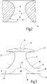
2 in stark vergrößerter Darstellung einen Längsschnitt durch einen Formhohlraum gemäß der Darstellung nach der1 ; -
3 ein einzelnes Verschlusselement, wie es mit dem Formhohlraum nach der2 herstellbar ist; -
4 eine Unteransicht auf das Verschlusselement nach3 ; -
5 eine Draufsicht auf Verschlusselemente, von denen in der3 ein einzelnes dargestellt ist.
-
1 a highly schematically simplified and partially sectioned side view of a device for carrying out a method for obtaining the closure part according to the invention; -
2 in a greatly enlarged view a longitudinal section through a mold cavity as shown in FIG1 ; -
3 a single closure member as provided with the mold cavity of FIG2 is manufacturable; -
4 a bottom view of the closure element3 ; -
5 a top view of closure elements, of which in FIG3 a single one is shown.
Zu diesem Zweck weist die Formwalze 5 am Umfang ein Sieb 11 auf mit einzelnen Formhohlräumen 12. Ein dahingehender Formhohlraum 12 ist beispielhaft in der
Die
Wie die
Zum Erhalt der angesprochenen Formhohlräume 12 mit ihrem rotationssymmetrischen Aufbau, vorzugsweise in Form eines Hyperboloids, haben sich galvanische Beschichtungsverfahren erwiesen, bei dem zunächst ein zylindrischer Formhohlraum (nicht dargestellt) derart mit einem Beschichtungswerkstoff beschichtet wird, bis sich der konvexe Bahnverlauf 14 einstellt. Ferner ließe sich gegebenenfalls auch über ein Laser- oder Ätzverfahren der konvexe Bahnverlauf 14 aus einem Sieb- oder Gitter-Vollmaterial erzeugen.Galvanic coating processes have proven effective in obtaining the
Das in der
Ferner lässt sich gemäß der Darstellung nach der
Wie sich des Weiteren aus der
Die jeweilige kraterartige Vertiefung 23 verläuft, ausgehend von der eben verlaufenden weiteren Seite 22 des Trägerteils 10 von dort überstandsfrei aus, stetig bis zum Kratergrund 24. Die jeweilige Vertiefung 23 geht in einem Längsschnitt gemäß der Darstellung nach der
Des Weiteren ist in Blickrichtung auf die
Vorzugsweise ist jedem Verschlusselement zugeordnet eine solche Vertiefung 23 vorhanden, wobei alle Verschlusselemente bevorzugt gleich ausgebildet sind, ebenso wie alle Vertiefungen 23 zueinander. Dies gilt auch entsprechend für die kopfseitige konvexe Ausnehmung 20 auf der Oberseite des jeweiligen Kopfteiles 16 eines Verschlusselementes. Wie insbesondere die
Wie sich weiter aus der
Als Kunststoffe für das Verschlussteil werden solche Materialien bevorzugt eingesetzt mit einer Reißdehnung größer 30% und die vorstehend angegebenen Größen- und Dickenabmessungen sind bevorzugt mit einem DM2000-Dickenmessgerät der Firma Wolff-Messtechnik gemessen. Neben den üblichen Kunststoffmaterialien zum Herstellen solcher Verschlussteile können auch biologisch abbaubare Werkstoffe in Frage kommen, die vorzugsweise auf der Basis nachwachsender oder petrochemischer Rohstoffe oder aus Kombinationen beider hergestellt werden können.Such materials are preferably used as plastics for the closure part with an elongation at break greater than 30% and the size and thickness dimensions given above are preferably measured with a DM2000 thickness measuring device from Wolff-Messtechnik. In addition to the usual plastic materials for producing such closure parts, biodegradable materials can also be considered, which can preferably be produced on the basis of renewable or petrochemical raw materials or a combination of both.
An der Stelle der Entformung 27 (vgl.
Eine andere Möglichkeit die krater- oder dellenartigen Vertiefungen 23 einzubringen, besteht darin, dass man entweder die Druckwalze 3 und/oder eine Entformungswalze 28 (s.
ZITATE ENTHALTEN IN DER BESCHREIBUNGQUOTES INCLUDED IN DESCRIPTION
Diese Liste der vom Anmelder aufgeführten Dokumente wurde automatisiert erzeugt und ist ausschließlich zur besseren Information des Lesers aufgenommen. Die Liste ist nicht Bestandteil der deutschen Patent- bzw. Gebrauchsmusteranmeldung. Das DPMA übernimmt keinerlei Haftung für etwaige Fehler oder Auslassungen.This list of documents cited by the applicant was generated automatically and is included solely for the better information of the reader. The list is not part of the German patent or utility model application. The DPMA assumes no liability for any errors or omissions.
Zitierte PatentliteraturPatent Literature Cited
- DE 10039937 A1 [0002, 0008]DE 10039937 A1 [0002, 0008]
- DE 19646318 A1 [0003]DE 19646318 A1 [0003]
- DE 102004058257 B4 [0009]DE 102004058257 B4 [0009]
Claims (10)
Priority Applications (7)
| Application Number | Priority Date | Filing Date | Title |
|---|---|---|---|
| DE102020007585.1A DE102020007585A1 (en) | 2020-12-11 | 2020-12-11 | locking part |
| EP21815492.0A EP4132315A1 (en) | 2020-12-11 | 2021-11-19 | Fastener part |
| US18/013,606 US20230320464A1 (en) | 2020-12-11 | 2021-11-19 | Fastener part |
| CN202180060356.2A CN116249609A (en) | 2020-12-11 | 2021-11-19 | Fastener piece |
| PCT/EP2021/082285 WO2022122345A1 (en) | 2020-12-11 | 2021-11-19 | Fastener part |
| JP2023512242A JP2023547013A (en) | 2020-12-11 | 2021-11-19 | fastener parts |
| TW110146045A TW202228545A (en) | 2020-12-11 | 2021-12-09 | Fastener part |
Applications Claiming Priority (1)
| Application Number | Priority Date | Filing Date | Title |
|---|---|---|---|
| DE102020007585.1A DE102020007585A1 (en) | 2020-12-11 | 2020-12-11 | locking part |
Publications (1)
| Publication Number | Publication Date |
|---|---|
| DE102020007585A1 true DE102020007585A1 (en) | 2022-06-15 |
Family
ID=78806525
Family Applications (1)
| Application Number | Title | Priority Date | Filing Date |
|---|---|---|---|
| DE102020007585.1A Pending DE102020007585A1 (en) | 2020-12-11 | 2020-12-11 | locking part |
Country Status (7)
| Country | Link |
|---|---|
| US (1) | US20230320464A1 (en) |
| EP (1) | EP4132315A1 (en) |
| JP (1) | JP2023547013A (en) |
| CN (1) | CN116249609A (en) |
| DE (1) | DE102020007585A1 (en) |
| TW (1) | TW202228545A (en) |
| WO (1) | WO2022122345A1 (en) |
Citations (7)
| Publication number | Priority date | Publication date | Assignee | Title |
|---|---|---|---|---|
| US5460769A (en) | 1992-03-10 | 1995-10-24 | Nifco Inc. | Method and apparatus for manufacturing a separable plastic fastener |
| DE19646318A1 (en) | 1996-11-09 | 1998-05-14 | Binder Gottlieb Gmbh & Co | Efficient process for the production of an adhesive closure part from thermoplastic plastic |
| DE10039937A1 (en) | 2000-08-16 | 2002-03-07 | Binder Gottlieb Gmbh & Co | Method of making an adhesive fastener part |
| US20030074771A1 (en) | 2000-10-19 | 2003-04-24 | Duffy Leonard Arnold | Slidingly engagable fasteners and method of manufacturing same |
| DE102004058257B4 (en) | 2004-12-03 | 2007-05-16 | Binder Gottlieb Gmbh & Co Kg | Method for producing a carrier web and carrier web |
| US8375529B1 (en) | 2008-07-29 | 2013-02-19 | Leonard Arnold Duffy | Touch engageable fastener |
| US20180020782A1 (en) | 2016-07-21 | 2018-01-25 | Florin Morar | Fastening Device |
Family Cites Families (11)
| Publication number | Priority date | Publication date | Assignee | Title |
|---|---|---|---|---|
| ES453167A1 (en) * | 1976-11-10 | 1977-11-16 | Velero Espanola S A | Fastener device and method of manufacturing |
| US5845375A (en) * | 1990-09-21 | 1998-12-08 | Minnesota Mining And Manufacturing Company | Mushroom-type hook strip for a mechanical fastener |
| JPH09238714A (en) * | 1996-03-04 | 1997-09-16 | Ykk Corp | Integrally molded hook-and-loop fastener made of synthetic resin |
| DE19828856C1 (en) * | 1998-06-29 | 1999-10-07 | Binder Gottlieb Gmbh & Co | Process to mold a holding stud on a thermoplastic tab for baby nappies |
| JP3818431B2 (en) * | 2001-03-08 | 2006-09-06 | Ykk株式会社 | Integrally molded surface fastener, its continuous manufacturing method and continuous manufacturing apparatus |
| DE10123205A1 (en) * | 2001-05-12 | 2002-11-28 | Binder Gottlieb Gmbh & Co | Production of section of touch-and-close fastener with support strip with integral hooks comprises adding mushroom-shaped layer of duroplast to top of hooks |
| US7516524B2 (en) * | 2005-03-11 | 2009-04-14 | Velcro Industries B.V. | Hook fastener components and methods of their manufacture |
| US20080134476A1 (en) * | 2006-12-11 | 2008-06-12 | Steindorf Eric C | Fastener having adjustable fastening strength |
| WO2014128201A1 (en) * | 2013-02-22 | 2014-08-28 | Velcro Industries B.V. | Touch fastener structures |
| US10016022B2 (en) * | 2015-10-07 | 2018-07-10 | Ykk Corporation | Hook fastener and methods for manufacturing same |
| EP4049553A1 (en) * | 2018-12-03 | 2022-08-31 | Velcro IP Holdings LLC | Male touch fastener elements |
-
2020
- 2020-12-11 DE DE102020007585.1A patent/DE102020007585A1/en active Pending
-
2021
- 2021-11-19 JP JP2023512242A patent/JP2023547013A/en active Pending
- 2021-11-19 CN CN202180060356.2A patent/CN116249609A/en active Pending
- 2021-11-19 US US18/013,606 patent/US20230320464A1/en active Pending
- 2021-11-19 WO PCT/EP2021/082285 patent/WO2022122345A1/en active Application Filing
- 2021-11-19 EP EP21815492.0A patent/EP4132315A1/en active Pending
- 2021-12-09 TW TW110146045A patent/TW202228545A/en unknown
Patent Citations (7)
| Publication number | Priority date | Publication date | Assignee | Title |
|---|---|---|---|---|
| US5460769A (en) | 1992-03-10 | 1995-10-24 | Nifco Inc. | Method and apparatus for manufacturing a separable plastic fastener |
| DE19646318A1 (en) | 1996-11-09 | 1998-05-14 | Binder Gottlieb Gmbh & Co | Efficient process for the production of an adhesive closure part from thermoplastic plastic |
| DE10039937A1 (en) | 2000-08-16 | 2002-03-07 | Binder Gottlieb Gmbh & Co | Method of making an adhesive fastener part |
| US20030074771A1 (en) | 2000-10-19 | 2003-04-24 | Duffy Leonard Arnold | Slidingly engagable fasteners and method of manufacturing same |
| DE102004058257B4 (en) | 2004-12-03 | 2007-05-16 | Binder Gottlieb Gmbh & Co Kg | Method for producing a carrier web and carrier web |
| US8375529B1 (en) | 2008-07-29 | 2013-02-19 | Leonard Arnold Duffy | Touch engageable fastener |
| US20180020782A1 (en) | 2016-07-21 | 2018-01-25 | Florin Morar | Fastening Device |
Also Published As
| Publication number | Publication date |
|---|---|
| US20230320464A1 (en) | 2023-10-12 |
| CN116249609A (en) | 2023-06-09 |
| EP4132315A1 (en) | 2023-02-15 |
| WO2022122345A1 (en) | 2022-06-16 |
| TW202228545A (en) | 2022-08-01 |
| JP2023547013A (en) | 2023-11-09 |
Similar Documents
| Publication | Publication Date | Title |
|---|---|---|
| EP1309257B1 (en) | Method for producing an adhesive closing element | |
| EP0932346B1 (en) | Method and device for producing a hook-and-pile type closure part from thermoplastic plastics | |
| EP1091664B1 (en) | Method for producing a fixing closure element | |
| EP1729607B1 (en) | Process for creating adhesion elements on a substrate material | |
| EP1827795B1 (en) | Method for producing a supporting web, and supporting web | |
| DE60118614T2 (en) | METHOD AND FORM FOR PRODUCING A LAYERED PART, ESPECIALLY REACTION INJECTION METHOD FOR PRODUCING A POLYURETHANE SKIN | |
| EP2129254B1 (en) | Method for the production of a part of a hook and loop fastener together with a corresponding apparatus | |
| DE102015109855A1 (en) | Method for producing components, in particular elongated profiles from strip-shaped, pre-impregnated fibers (prepreg) | |
| EP1358855A1 (en) | Process for manufacturing parts by freeform laser-sintering | |
| DE102010044660A1 (en) | Fastener part | |
| EP2802233B1 (en) | Method for producing a plastics product and device for carrying out the method | |
| DE102007057905A1 (en) | Adhesive closure part and method for producing an adhesive closure part | |
| DE112016006458B4 (en) | Molded surface zipper | |
| DE102008027860A1 (en) | Adhesive closure part and method for producing an adhesive closure part | |
| DE102020007585A1 (en) | locking part | |
| WO2003051148A1 (en) | Method for producing an adhesive closure element | |
| EP1626636B1 (en) | Method for producing a contact-fastener part | |
| DE60008668T2 (en) | Method of helping to remove residues from a multi-layered three-dimensional object | |
| EP1387626A1 (en) | Method for producing a touch-and-close fastener element | |
| DE102017127130A1 (en) | closure element | |
| EP2796744B1 (en) | Leaf spring and method for its production | |
| DE102007015516B4 (en) | Plastic-fiber composite component in the form of a profile with over the length varying profile cross-section | |
| EP1679022B1 (en) | Plastics sheet product with densified underside | |
| DE3815063A1 (en) | METHOD AND DEVICE FOR PRODUCING A COMPONENT FROM PLASTIC | |
| DE102011054789A1 (en) | Nano-shape structure |
Legal Events
| Date | Code | Title | Description |
|---|---|---|---|
| R012 | Request for examination validly filed | ||
| R082 | Change of representative |
Representative=s name: KOHLER SCHMID MOEBUS PATENTANWAELTE PARTNERSCH, DE |
|
| R082 | Change of representative |
Representative=s name: KOHLER SCHMID MOEBUS PATENTANWAELTE PARTNERSCH, DE |