EP4131849A1 - Switching element, pse component and method for monitoring and protecting a podl network - Google Patents
Switching element, pse component and method for monitoring and protecting a podl network Download PDFInfo
- Publication number
- EP4131849A1 EP4131849A1 EP22182937.7A EP22182937A EP4131849A1 EP 4131849 A1 EP4131849 A1 EP 4131849A1 EP 22182937 A EP22182937 A EP 22182937A EP 4131849 A1 EP4131849 A1 EP 4131849A1
- Authority
- EP
- European Patent Office
- Prior art keywords
- voltage
- switching element
- network
- pse
- component
- Prior art date
- Legal status (The legal status is an assumption and is not a legal conclusion. Google has not performed a legal analysis and makes no representation as to the accuracy of the status listed.)
- Pending
Links
Images


Classifications
-
- H—ELECTRICITY
- H04—ELECTRIC COMMUNICATION TECHNIQUE
- H04L—TRANSMISSION OF DIGITAL INFORMATION, e.g. TELEGRAPHIC COMMUNICATION
- H04L12/00—Data switching networks
- H04L12/02—Details
- H04L12/10—Current supply arrangements
-
- G—PHYSICS
- G01—MEASURING; TESTING
- G01R—MEASURING ELECTRIC VARIABLES; MEASURING MAGNETIC VARIABLES
- G01R19/00—Arrangements for measuring currents or voltages or for indicating presence or sign thereof
- G01R19/165—Indicating that current or voltage is either above or below a predetermined value or within or outside a predetermined range of values
- G01R19/16504—Indicating that current or voltage is either above or below a predetermined value or within or outside a predetermined range of values characterised by the components employed
- G01R19/16519—Indicating that current or voltage is either above or below a predetermined value or within or outside a predetermined range of values characterised by the components employed using FET's
-
- G—PHYSICS
- G05—CONTROLLING; REGULATING
- G05F—SYSTEMS FOR REGULATING ELECTRIC OR MAGNETIC VARIABLES
- G05F1/00—Automatic systems in which deviations of an electric quantity from one or more predetermined values are detected at the output of the system and fed back to a device within the system to restore the detected quantity to its predetermined value or values, i.e. retroactive systems
- G05F1/10—Regulating voltage or current
- G05F1/46—Regulating voltage or current wherein the variable actually regulated by the final control device is dc
-
- H—ELECTRICITY
- H04—ELECTRIC COMMUNICATION TECHNIQUE
- H04L—TRANSMISSION OF DIGITAL INFORMATION, e.g. TELEGRAPHIC COMMUNICATION
- H04L12/00—Data switching networks
- H04L12/28—Data switching networks characterised by path configuration, e.g. LAN [Local Area Networks] or WAN [Wide Area Networks]
- H04L12/40—Bus networks
- H04L2012/4026—Bus for use in automation systems
-
- H—ELECTRICITY
- H04—ELECTRIC COMMUNICATION TECHNIQUE
- H04L—TRANSMISSION OF DIGITAL INFORMATION, e.g. TELEGRAPHIC COMMUNICATION
- H04L43/00—Arrangements for monitoring or testing data switching networks
- H04L43/50—Testing arrangements
Definitions
- the present invention relates to a switching element according to the preamble of claim 1, a PSE component according to the preamble of claim 6 and a method for monitoring and protecting a PoDL network according to the preamble of claim 8.
- Safety devices for fieldbus applications are known in the prior art and are functionally used for safe power limitation to protect people.
- the DE 10 2020 113 822 A1 discloses an output fuse in which the output switching elements do not have to be switched off cyclically for testing, since they are located in a permanently active control loop which monitors their functionality, the gate voltages being measured, among other things.
- This interconnection is only designed for bus technologies in which the data line is separated from the supply lines.
- PoDL Power over Data Line
- SPE Single Pair Ethernet
- PoDL data-carrying supply lines
- an electronic interconnection element of a PSE component for a PoDL network or network section comprising a voltage connection and/or voltage source, a first line for connecting a pole of the voltage connection to a first connection of a physical layer (PHY), a second line for connecting the second pole of the voltage connection to the second connection of the physical layer (PHY), at least one switching element in each of the lines, the switching elements being connected to at least one control unit comprising a microprocessor and can be controlled as a result, and at least one voltage measuring unit is provided, by means of which the voltage drop can be detected as a measured value across each switching element and can be fed to the microprocessor.
- the wiring provides that current and voltage are (at least) redundantly measured, calculated and compared in order to determine the power.
- the current measurement takes place (at least also) by measuring the gate voltages of at least two FETs (field effect transistors).
- an improved embodiment of the interconnection element consists in the two switching elements having a voltage as a manipulated variable in the conducting state, which is related to the conducting current, which are connected to the control unit in a data-conducting manner.
- At least one switching element is advantageously a field effect transistor (FET), in particular a normally closed (nc) field effect transistor.
- FET field effect transistor
- nc normally closed field effect transistor
- the switching elements can also be in the form of MOSFETs or IGBTs.
- the switching elements are structurally and functionally identical, ie are of identical or essentially identical design.
- the PSE component can be further improved in that the physical layer (PHY) has two connections, each of the connections being directly upstream of an interconnection of passive components, in particular at least one resistor and at least one capacitor.
- PHY physical layer
- the circuit element includes a PHY, a PSE component and a coupling with passive components.
- the coupling towards the PHY must be designed to be safety-related.
- the failure of a component must not lead to power being injected via this path. This can be done as suggested in IEEE 802.3cg:2019 to achieve intrinsic safety.
- the critical components are connected in duplicate, one after the other or next to each other, depending on their function.
- the invention includes a method for monitoring and protecting a PoDL network and/or network section, wherein at least one switching element is provided in two lines connected to a voltage source and the voltage drop across each switching element is measured, depending on the IST -Voltage measured values (controlled variable) the switching elements are controlled by means of a voltage (manipulated variable) which is related to the current flow (disturbance variable).
- the current flow is technically independently measured in both lines and the measured values and/or data derived from them are evaluated together in a processor unit by determining the current flow in each switching element using the control voltage and comparing the current flow of the two switching elements for monitoring.
- the current flow in each switching element is advantageously measured using the drive voltage (U_GS, gate voltage) the current flow disturbance variable, I-S), which means calculated from the drive voltages (U_GS, gate voltage). This determination takes place in both switching elements in parallel and independently.
- the network or network sections are monitored by means of the current flows (flow rates) generated and compared in this way and, based on this, any necessary process control, warning messages and/or shutdowns are initiated.
- the method therefore provides for the switching elements, such as the FET, to be located in a control loop.
- the flow current is determined using the control voltage (U_GS, gate voltage) and the flow current of the two switching elements is compared and monitored. If an inequality in the flow current is determined, both switching elements are switched off because the inequality indicates a fault that is either in the switching element itself or in an external potential coupled in.
- the redundantly measured flow rate is evaluated and compared with a specification such as an FET characteristic curve.
- a specification such as an FET characteristic curve.
- the current is not actively limited, but rather monitored and switched off if it is exceeded.
- the PHY transmission power is not separately measured, monitored or limited, but the actual supply and/or the voltage source itself is switched off completely.
- a transmission power of the PHY advantageously remains as an autonomous signal even after a shutdown, the transmission power of which is less than 0.5 watts.
- a further improved variant of the method provides that a SET characteristic curve is stored for each switching element and the resistance value and/or the gate voltage (U_GS) of the two switching elements changes within defined limits and the ACTUAL Value is compared with the TARGET characteristic and / or corridor of the TARGET characteristic of the respective switching element.
- the resistance value and/or the respective gate voltage (U_GS) can be changed individually or synchronously.
- a further, improved variant of the method provides that after a shutdown due to the detection of an unequal current intensity and/or an unequal current flow, a user intervention takes place before switching on again, in particular after an error analysis and/or error correction by a user or a specification by the controller , by specifying an output limitation or a power limitation, a renewed switch-on and/or normal operation takes place due to internal specifications of the controller.
- a PSE component is used in the method, which is designed according to one of the above embodiments and is operated accordingly.
- the method described here in the various embodiments can be used in particular for a supply and data network in which the data transmission and the power line take place together via a two-wire cable, in particular a single pair Ethernet (SPE) and/or twisted pair Ethernet (TPE) .
- SPE single pair Ethernet
- TPE twisted pair Ethernet
- the limitation of the current can be that the current is switched off completely to 0 A or to a defined value>0, in particular to a value of up to 100 mA.
- the advantage of not switching off completely is that data transmission can be continued with the low current flow, for example in order to be able to transmit status data or forward control commands.
- the particular advantage is that the same FETs are used as the output switching elements for current measurement, which are also used for switching off, so that no additional components are installed in the power path must.
- This connection also enables safe power limitation and shutdown of an electronic component or device that itself does not have a safety function, such as a frequency converter.
- Complex, functionally safe bus communication can be dispensed with with the interconnection according to the invention, since the power limitation and, if necessary, shutdown take place at a higher level.
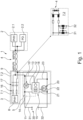
- the PoDL network or network section 1 shown is structured as regularly provided for in IEEE 802.3cg:2019. It includes a physical layer 8 (PHY) for communication of the data on both sides of the SPE link 4, namely on the side of the PSE 3 (Power Sourcing Equipment) and on the other side of the SPE link, the PD 2 (Powered Device ).
- PSE Power Sourcing Equipment
- the embodiment according to the invention relates to the PSE 3 side, so that the PD 2 is not explained in any more detail and comprises the (micro)electronic parts and components familiar to the person skilled in the art.
- the PSE 3 essentially includes a protective circuit 9 from the PHY 8 and the passive components 7.1, 7.2 and a switching element 5.
- the protective circuit 9 includes the passive components 7.1 and 7.2 for coupling the PHY and PSE.
- passive components 7.1, 7.2 are necessary for the coupling.
- the passive component 7.1 must be designed to be safety-related.
- the transmission power of the PHY 8 is the lowest power level.
- the recognition of the PD 2 via a detection voltage and the transmission of the power classes via SCCP (Serial Communication Classification Protocol) correspond to the usual standards.
- a passive component 7.1 is provided in the protective circuit 9, which has a series-connected resistor 16 and a capacitor 17 comprises.
- the structure of the second, passive component 7.2 is enlarged in the lower detailed view and shown with the individual components.
- the interconnection element 5 includes a voltage connection 30 (positive position) with a first line 31, which leads to the first connection 8.1 of a physical layer (PHY) 8.
- the second line 32 connects the other voltage connection 30 (negative pole) to the second connection 8.2 of the PHY 8 of the PSE 3.
- Both lines 31, 32 each include a switching element 10, 20 designed as an FET.
- the voltage connection 30 can lead to an external source , as in figure 1 indicated or formed into an integrated source such as a battery, as in figure 2 shown.
- a central control unit 15 picks up the voltage (U_DS) across the respective switching element 10, 20 (FET) via the pair of lines 11, 13 in the first line 31 and via the pair of lines 21, 23 in the second line 32.
- each switching element 10, 20 is controlled and regulated via a respectively associated control line 12, 22, which is connected to the control unit 15.
- the control unit 15, which for example has a circuit board as the base support, also includes a microprocessor 6 for at least part of the data processing and a voltmeter 18. Other, customary further (micro)electronic elements of the control unit 15 are not shown.
- the regulation takes place electronically via operational amplifiers, but can also take place via the microprocessor.
- the microprocessor is used for control and monitoring purposes.
- the functionally safe shutdown according to the invention relates only to the PSE 3.
- the power can only be limited to the maximum transmission power of the PHY 8.
- Ethernet can optionally be used as a black channel for a safe protocol. It is thus possible to operate a safe protocol (e.g. PROFIsafe or CIPP Safety). Both a secure protocol and a standard protocol can be operated.
- a safe protocol e.g. PROFIsafe or CIPP Safety
- Both a secure protocol and a standard protocol can be operated.
- the advantage of the invention consists in the fact that the higher-level safe shutdown is possible even without a safe protocol.
- an additional ammeter 14 is also shown as an optional extension, which is also connected to the control unit 15 via a data line with a dot-dash line.
- the current flow thus measured in the positive pole line 31 can be compared with the currents determined from the voltages and used for monitoring.
- this additional, separate current measurement can be further improved if an additional ammeter 14.1, 14.2 is provided in both lines 31, 32 and the currents determined in this way are compared and used for monitoring.
- the switching elements are in the switched-on state in a control loop 24 in which the voltage 34 (U_DS) is kept constant as a controlled variable.
- This voltage 34 is tapped off via the lines 11, 13 in the line 31 and via the lines 21, 23 in the line 32, as in FIGS figures 1 and 2 shown.
- the (gate) voltage 35 (U_GS) applied via the control lines 12, 22 is in a typical ratio to the disturbance variable 33 (I_S) of the flowing current. This relationship can be taken from a component-specific characteristic curve for each actuating element 10, 12, as in the lower graph in FIG figure 3 was presented.
- the output voltage 19 can optionally be read back via the lines 13 in the first line 31 (plus pole) and the second line 32 (minus pole) via the line 23 and also (redundantly) measured be what was previously referred to as "behind" the switching elements 10,20.
- the switching elements 10, 20 can be measured in an analogous manner via the pair of lines 11, 21.
- the PHY 8 is limited to the transmission power. This does not require the performance or the measure current accurately.
- the current measurement essentially serves to monitor the switching elements 10, 20 designed as FETs. Thus, in this variant, only two safe power stages are normally provided.
- a safety-related measurement of the current and the voltage can be carried out, from which the power can be calculated. This is compared with a specification, such as the performance classes according to IEEE 802.3cg:2019 according to the table above. For this purpose, the specification must always be securely configured. Any Skinny Client Control Protocol (SCCP) present has a control effect. If the specification is not met, a safe shutdown is initiated.
- SCCP Skinny Client Control Protocol
Abstract
Die vorliegende Erfindung betrifft ein Elektronisches Verschaltungselement eines PSE-Bauteils für einen PoDL Netz- oder Netzabschnitt, insbesondere ein SPE-Netz- und/oder Netzabschnitt, umfassend- einen Spannungsanschluss und/oder Spannungsquelle,- eine erste Leitung zum Verbinden eines Pols des Spannungsanschlusses mit einem ersten Anschluss) eines Physical Layers (PHY),- eine zweite Leitung zum Verbinden des zweiten Pols des Spannungsanschlusses mit dem zweiten Anschluss des Physical Layers (PHY),- mindestens ein Schaltelement in jeder der Leitungen, wobei die Schaltelemente mit mindestens einer einen Mikroprozessor umfassende Regeleinheit verbunden und hierdurch regelbar sind, und wobei mindestens eine Spannungsmesseinheit vorgesehen ist, mittels welcher der Spannungsabfall als Messwert über jedem Schaltelement erfassbar und der Regelungseinheit zuleitbar ist. Weiterhin ist von der Erfindung ein PSE-Bauteil und ein Verfahren zur Überwachung des PSE-Bauteils umfasst.The present invention relates to an electronic interconnection element of a PSE component for a PoDL network or network section, in particular an SPE network and/or network section, comprising - a voltage connection and/or voltage source, - a first line for connecting a pole of the voltage connection to a first connection) of a physical layer (PHY),- a second line for connecting the second pole of the voltage connection to the second connection of the physical layer (PHY),- at least one switching element in each of the lines, the switching elements having at least one microprocessor comprehensive control unit are connected and thereby controlled, and wherein at least one voltage measuring unit is provided, by means of which the voltage drop can be detected as a measured value across each switching element and the control unit can be fed. The invention also includes a PSE component and a method for monitoring the PSE component.
Description
Die vorliegende Erfindung betrifft ein Verschaltungselement nach dem Oberbegriff des Anspruchs 1, ein PSE-Bauteil nach dem Oberbegriff des Anspruchs 6 und ein Verfahren zur Überwachung und zum Schutz eines PoDL-Netzes nach dem Oberbegriff des Anspruchs 8.The present invention relates to a switching element according to the preamble of
Im Stand der Technik sind Sicherungsvorrichtungen für Feldbusanwendungen bekannt und dienen funktional zur sicheren Leistungsbegrenzung zum Schutz von Personen.Safety devices for fieldbus applications are known in the prior art and are functionally used for safe power limitation to protect people.
Die
Aus der
Es ist die Aufgabe der vorliegenden Erfindung eine verbesserte Verschaltung auch für datentragende Versorgungsleitungen vorzuschlagen (PoDL), bei der die Leistung sicher begrenzt wird.It is the object of the present invention to propose an improved circuit for data-carrying supply lines (PoDL), in which the power is safely limited.
Diese Aufgabe wird erfindungsgemäß gelöst durch ein Verschaltungselement nach den Merkmalen des Anspruchs 1, ein PSE-Bauteil nach den Merkmalen des Anspruchs 6 und ein Verfahren nach den Merkmalen des Anspruches 8. Vorteilhafte Ausgestaltungen sind in den jeweiligen, zugehörigen Unteransprüchen angegeben.This object is achieved according to the invention by a switching element according to the features of
Danach wird die Aufgabe gelöst durch ein elektronisches Verschaltungselement eines PSE-Bauteils für einen PoDL Netz- oder Netzabschnitt, insbesondere ein SPE-Netz- oder/Netzabschnitt, umfassend einen Spannungsanschluss und/oder Spannungsquelle, eine erste Leitung zum Verbinden eines Pols des Spannungsanschlusses mit einem ersten Anschluss eines Physical Layers (PHY), eine zweite Leitung zum Verbinden des zweiten Pols des Spannungsanschlusses mit dem zweiten Anschluss des Physical Layers (PHY), mindestens ein Schaltelement in jeder der Leitungen, wobei die Schaltelemente mit mindestens einer einen Mikroprozessor umfassenden Regeleinheit verbunden und hierdurch regelbar sind, und wobei mindestens eine Spannungsmesseinheit vorgesehen ist, mittels welcher der Spannungsabfall als Messwert über jedem Schaltelement erfassbar und dem Mikroprozessor zuleitbar ist.According to this, the object is achieved by an electronic interconnection element of a PSE component for a PoDL network or network section, in particular an SPE network or/network section, comprising a voltage connection and/or voltage source, a first line for connecting a pole of the voltage connection to a first connection of a physical layer (PHY), a second line for connecting the second pole of the voltage connection to the second connection of the physical layer (PHY), at least one switching element in each of the lines, the switching elements being connected to at least one control unit comprising a microprocessor and can be controlled as a result, and at least one voltage measuring unit is provided, by means of which the voltage drop can be detected as a measured value across each switching element and can be fed to the microprocessor.
Die Verschaltung sieht verkürzt gesprochen vor, dass Strom und Spannung (wenigstens) redundant gemessen, verrechnet und verglichen werden, um die Leistung zu ermitteln. Die Strommessung findet dabei (zumindest auch) durch die Messung der Gatespannungen mindestens zweier FETs (Feldeffekttransistors) statt.In a nutshell, the wiring provides that current and voltage are (at least) redundantly measured, calculated and compared in order to determine the power. The current measurement takes place (at least also) by measuring the gate voltages of at least two FETs (field effect transistors).
Mit diesem Verschaltungselement wird eine funktional sichere Leistungsbegrenzung nach der IEC 61508 erreicht. Weiterhin kann zusätzlich eine Eigensicherheit nach der IEEE 802.3cg:2019 erreicht werden. Hierbei besteht eine verbesserte Ausführungsführungsform des Verschaltungselements darin, dass die beiden Schaltelemente im leitenden Zustand eine Spannung als Stellgröße aufweisen, die in Relation zum durchleitenden Strom steht, welche datenleitend mit der Regeleinheit verbunden sind.Functionally safe power limitation according to IEC 61508 is achieved with this interconnection element. Furthermore, intrinsic safety according to IEEE 802.3cg:2019 can also be achieved. In this case, an improved embodiment of the interconnection element consists in the two switching elements having a voltage as a manipulated variable in the conducting state, which is related to the conducting current, which are connected to the control unit in a data-conducting manner.
Vorteilhafterweise ist hierbei mindestens ein Schaltelement ein Feldeffekttransistor (FET), insbesondere ein normally closed (nc) Feldeffekttransistor. Alternativ können die Schaltelemente auch als MOSFET oder IGBT ausgebildet sein. Es ist insbesondere vorteilhaft, um die Spannungen und Ströme zu vergleichen, wenn die Schaltelemente bau- und funktionsgleich sind, also identisch oder im Wesentlichen identisch ausgebildet sind.At least one switching element is advantageously a field effect transistor (FET), in particular a normally closed (nc) field effect transistor. Alternatively can the switching elements can also be in the form of MOSFETs or IGBTs. In order to compare the voltages and currents, it is particularly advantageous if the switching elements are structurally and functionally identical, ie are of identical or essentially identical design.
Von der Erfindung ist auch ein (Powering Sourcing Equipment) PSE-Bauteil für ein PoDL Netz- und/oder einen PoDL-Netzabschnitt umfasst, insbesondere ein SPE-Netz- und/oder/Netzabschnitt, das die folgenden Komponenten umfasst
- ein mikroelektronisches Bauteil mit einem Physical Layer (PHY), welches über eine Leitung, insbesondere eine SPE-Verbindung (TPE) mit einem Powered Device (PD) verbindbar ist,
- eine Sicherheitsschaltung, welche eingangs eine Spannungsquelle umfasst und/oder hiermit verbindbar ist, wobei die Sicherheitsschaltung dem mikroelektronischen Bauteil vorgelagert ist, wobei die Sicherheitsschaltung als Verschaltungselement nach einem der vorherigen Ansprüche ausgebildet ist. Hierbei meint "vorgelagert", dass zwischen dem Stromzufluss einer Spannungsquelle und dem einen PHY umfassenden mikroelektronischen Bauteil sowie dem Powered Device (PD) die Sicherheitsschaltung als Überwachungs- und Schutzeinrichtung vorgesehen ist.
- a microelectronic component with a physical layer (PHY), which can be connected to a powered device (PD) via a line, in particular an SPE connection (TPE),
- a safety circuit which initially comprises a voltage source and/or can be connected thereto, the safety circuit being upstream of the microelectronic component, the safety circuit being designed as a circuit element according to one of the preceding claims. In this context, “upstream” means that the safety circuit is provided as a monitoring and protective device between the current inflow of a voltage source and the microelectronic component comprising a PHY and the powered device (PD).
Das PSE-Bauteil kann dahingehend weiter verbessert werden, indem der Physical Layer (PHY) zwei Anschlüsse aufweist, wobei jedem der Anschlüsse unmittelbar vorgelagert eine Verschaltung passiver Bauelemente, insbesondere mindestens eines Widerstandes und mindestens eine Kapazität.The PSE component can be further improved in that the physical layer (PHY) has two connections, each of the connections being directly upstream of an interconnection of passive components, in particular at least one resistor and at least one capacitor.
Das Verschaltungselement beinhaltet einen PHY, ein PSE-Bauteil und eine Kopplung mit passiven Bauelementen. Die Kopplung Richtung PHY muss sicherheitsgerichtet ausgelegt sein. Der Ausfall eines Bauteils darf nicht dazu führen, dass über diesen Weg Leistung eingekoppelt wird. Das kann so ausgeführt werden, wie es in der der IEEE 802.3cg:2019 zum Erreichen von Eigensicherheit vorgeschlagen wird. Dort werden die kritischen Bauteile doppelt, je nach Funktion hintereinander oder nebeneinander geschaltet.The circuit element includes a PHY, a PSE component and a coupling with passive components. The coupling towards the PHY must be designed to be safety-related. The failure of a component must not lead to power being injected via this path. This can be done as suggested in IEEE 802.3cg:2019 to achieve intrinsic safety. There, the critical components are connected in duplicate, one after the other or next to each other, depending on their function.
Weiterhin ist von der Erfindung ein Verfahren zur Überwachung und Schutz eines PoDL-Netzes und/oder Netzabschnitts umfasst, wobei in zwei mit einer Spannungsquelle verbunden Leitungen jeweils mindestens ein Schaltelement vorgesehen ist und der Spannungsabfall über jedem Schaltelement gemessen wird, wobei in Abhängigkeit von den IST-Spannungsmesswerten (Regelgröße) die Schaltelemente mittels einer Spannung (Stellgröße) angesteuert werden, die in Relation zum Stromfluss (Störgröße) steht.Furthermore, the invention includes a method for monitoring and protecting a PoDL network and/or network section, wherein at least one switching element is provided in two lines connected to a voltage source and the voltage drop across each switching element is measured, depending on the IST -Voltage measured values (controlled variable) the switching elements are controlled by means of a voltage (manipulated variable) which is related to the current flow (disturbance variable).
Bei einer verbesserten Verfahrensvariante wird in beiden Leitungen der Stromfluss technisch unabhängig gemessen und die Messwerte und/oder hieraus abgeleitete Daten gemeinsam in einer Prozessoreinheit ausgewertet, indem der Stromfluss in jedem Schaltelement anhand der Ansteuerspannung ermittelt und der Stromfluss der beiden Schaltelemente zur Überwachung verglichen wird.In an improved variant of the method, the current flow is technically independently measured in both lines and the measured values and/or data derived from them are evaluated together in a processor unit by determining the current flow in each switching element using the control voltage and comparing the current flow of the two switching elements for monitoring.
Vorteilhafterweise wird der Stromfluss in jedem Schaltelement anhand der Ansteuerspannung (U_GS, Gatespannung) der Stromfluss Störgröße, I-S)gemessen, das bedeutet rechnerisch aus den Ansteuerspannungen (U_GS, Gatespannung) ermittelt. Diese Ermittlung erfolgt in beiden Schaltelementen parallel und unabhängig. Mittels der so generierten und verglichenen Stromflüsse (Durchflussströme) wird das Netz oder Netzabschnitte überwacht und basierend hierauf gegebenenfalls erforderliche Prozesssteuerung, Warnmeldungen und/oder Abschaltungen veranlasst.The current flow in each switching element is advantageously measured using the drive voltage (U_GS, gate voltage) the current flow disturbance variable, I-S), which means calculated from the drive voltages (U_GS, gate voltage). This determination takes place in both switching elements in parallel and independently. The network or network sections are monitored by means of the current flows (flow rates) generated and compared in this way and, based on this, any necessary process control, warning messages and/or shutdowns are initiated.
Ein Verfahrensverbesserung besteht darin, dass der IST-Spannungsmesswert auf mindestens einem der Leitungsabschnitten der mit der Spannungsquelle verbunden Leitungen vor oder nach den Schaltelementen abgegriffen wird, nämlich
- zwischen Spannungsquelle und den Schaltelementen (vor) und/oder
- von der Spannungsquelle aus gesehen nach den Schaltelementen abgegriffen wird. Im ersten Fall ("vor" den Schaltelementen) wird die IST-Spannung auf der Source-Seite des Schaltelements in der Pluspol-Leitung und auf der Drain-Seite des Schaltelements in der Minuspol-Leitung abgegriffen. Im zweiten Fall ("nach" den Schaltelementen) wird die IST-Spannung auf der Drain-Seite des Schaltelements in der Pluspol-Leitung und auf der Source-Seite des Schaltelements in der Minuspol-Leitung abgegriffen. Die beiden IST-Spannungen können parallel, sequenziell und/oder getaktet zur Überwachung gemessen werden.
- between the voltage source and the switching elements (before) and/or
- seen from the voltage source after the switching elements. In the first case ("before" the switching elements), the ACTUAL voltage is tapped off on the source side of the switching element in the positive pole line and on the drain side of the switching element in the negative pole line. In the second case ("after" the switching elements), the ACTUAL voltage is tapped off on the drain side of the switching element in the positive pole line and on the source side of the switching element in the negative pole line. The two ACTUAL voltages can be measured in parallel, sequentially and/or clocked for monitoring.
Bei dem Verfahren ist also vorgesehen, dass sich die Schaltelemente, wie beispielsweise die FET, in einem Regelkreis befinden. Parallel wird der Durchflussstrom anhand der Ansteuerspannung (U_GS, Gatespannung) ermittelt und der Durchflussstrom der beiden Schaltelemente verglichen und hierüber überwacht. Wird eine Ungleichheit des Durchflussstroms ermittelt, werden beide Schaltelemente abgeschaltet, weil die Ungleichheit auf einen Fehler verweist, der entweder im Schaltelement selbst oder in einem eingekoppelten Fremdpotential besteht.The method therefore provides for the switching elements, such as the FET, to be located in a control loop. At the same time, the flow current is determined using the control voltage (U_GS, gate voltage) and the flow current of the two switching elements is compared and monitored. If an inequality in the flow current is determined, both switching elements are switched off because the inequality indicates a fault that is either in the switching element itself or in an external potential coupled in.
Hierbei wird der redundant gemessene Durchflussstrom ausgewertet und mit einer Vorgabe, wie einer FET-Kennkurve, verglichen. Der Strom wird dabei im Normalfall nicht aktiv begrenzt, sondern überwacht und bei Überschreitung abgeschaltet. Die PHY Sendeleistung wird nicht gesondert gemessen, überwacht oder begrenzt, sondern die eigentliche Versorgung und/oder die Spannungsquelle selbst wird komplett abgeschaltet. Vorteilhafterweise verbleibt eine Sendeleistung des PHY als autonomes Signal auch nach einer Abschaltung, dessen Sendeleistung kleiner 0,5 Watt ist.Here, the redundantly measured flow rate is evaluated and compared with a specification such as an FET characteristic curve. Normally, the current is not actively limited, but rather monitored and switched off if it is exceeded. The PHY transmission power is not separately measured, monitored or limited, but the actual supply and/or the voltage source itself is switched off completely. A transmission power of the PHY advantageously remains as an autonomous signal even after a shutdown, the transmission power of which is less than 0.5 watts.
Zur Überwachung der Funktionsweise und Funktionsfähigkeit der Schaltelemente selbst, ist bei einer weiter verbesserten Verfahrensvariante vorgesehen, dass eine SOLL-Kennkurve für jedes Schaltelement gespeichert wird und der Widerstandswert und/oder die Gatespannung (U_GS) der beiden Schaltelemente in definierten Grenzen verändert und der IST-Wert mit der SOLL-Kennlinie und/oder Korridor der SOLL-Kennlinie des jeweiligen Schaltelements verglichen wird. Die Änderung des Widerstandswertes und/oder der jeweiligen Gatespannung (U_GS) kann einzeln oder synchron erfolgen.In order to monitor the functioning and functionality of the switching elements themselves, a further improved variant of the method provides that a SET characteristic curve is stored for each switching element and the resistance value and/or the gate voltage (U_GS) of the two switching elements changes within defined limits and the ACTUAL Value is compared with the TARGET characteristic and / or corridor of the TARGET characteristic of the respective switching element. The resistance value and/or the respective gate voltage (U_GS) can be changed individually or synchronously.
Eine weitere, verbesserte Verfahrensvariante sieht vor, dass nach einer Abschaltung wegen einer Erfassung einer ungleichen Stromstärke und/oder eines ungleichen Stromflusses, ein Benutzereingriff vor einer erneuten Einschaltung erfolgt, insbesondere nach einer Fehleranalyse und/oder Fehlerbehebung durch einen Benutzer oder einer Vorgabe der Steuerung erfolgt, indem eine Ausgangsbegrenzung oder eine Leistungsbegrenzung vorgegeben wurde, erfolgt eine erneute Einschaltung und/oder der Normalbetrieb aufgrund interner Vorgaben der Steuerung.A further, improved variant of the method provides that after a shutdown due to the detection of an unequal current intensity and/or an unequal current flow, a user intervention takes place before switching on again, in particular after an error analysis and/or error correction by a user or a specification by the controller , by specifying an output limitation or a power limitation, a renewed switch-on and/or normal operation takes place due to internal specifications of the controller.
Vorteilhafterweise wird bei dem Verfahren ein PSE-Bauteil eingesetzt, das nach einem der vorstehenden Ausführungsformen ausgebildet ist und entsprechend betrieben wird. Das hierin beschriebene Verfahren in den diversen Ausführungsformen kann insbesondere für ein Versorgungs- und Datennetzwerk verwendet werden, bei welchem die Datenübermittlung und die Stromleitung gemeinsam über ein zweiadriges Kabel erfolgt, insbesondere ein Single Pair Ethernet (SPE) und/oder Twisted Pair Ethernet (TPE).Advantageously, a PSE component is used in the method, which is designed according to one of the above embodiments and is operated accordingly. The method described here in the various embodiments can be used in particular for a supply and data network in which the data transmission and the power line take place together via a two-wire cable, in particular a single pair Ethernet (SPE) and/or twisted pair Ethernet (TPE) .
Dabei kann die Begrenzung des Stroms darin bestehen, dass eine vollständige Stromabschaltung auf 0 A erfolgt oder auf einen definierten Wert > 0 erfolgt, insbesondere auf einen Wert bis 100 mA. Der Vorteil einer nicht vollständigen Abschaltung besteht darin, dass mit dem geringen Stromfluss auch eine Datenübertragung fortgeführt werden kann, um beispielsweise Zustandsdaten zu übermitteln oder Steuerbefehle weiterleiten zu können.The limitation of the current can be that the current is switched off completely to 0 A or to a defined value>0, in particular to a value of up to 100 mA. The advantage of not switching off completely is that data transmission can be continued with the low current flow, for example in order to be able to transmit status data or forward control commands.
Der besondere Vorteil besteht darin, dass dieselben FETs als Ausgansschaltelemente zur Strommessung genutzt werden, die auch zur Abschaltung genutzt werden, so dass keine zusätzlichen Bauteile im Leistungspfad eingebaut werden müssen. Somit wird auch mittels dieser Verschaltung eine sichere Leistungsbegrenzung und Abschaltung eines elektronischen Bauteils oder Gerätes ermöglicht, welches selbst keine Sicherheitsfunktion umfasst, wie beispielsweise ein Frequenzumrichter. Auf eine aufwändige funktional sichere Bus-Kommunikation kann mit der erfindungsgemäßen Verschaltung verzichtet werden, da die Leistungsbegrenzung und bedarfsweise Abschaltung übergeordnet stattfind.The particular advantage is that the same FETs are used as the output switching elements for current measurement, which are also used for switching off, so that no additional components are installed in the power path must. This connection also enables safe power limitation and shutdown of an electronic component or device that itself does not have a safety function, such as a frequency converter. Complex, functionally safe bus communication can be dispensed with with the interconnection according to the invention, since the power limitation and, if necessary, shutdown take place at a higher level.
Weitere Einzelheiten und Vorteile der Erfindung sollen nun anhand von in Zeichnungen dargestellten Ausführungsbeispielen näher erläutert.Further details and advantages of the invention will now be explained in more detail with reference to exemplary embodiments illustrated in the drawings.
Es zeigt:
- Fig. 1
- ein Schaltbild einer ersten Ausführungsform,
- Fig. 2
- ein Schaltbild einer weiteren Ausführungsform und
- Fig. 3
- eine Skizze der Schaltung sowie Graphen der Kennlinien der FET.
- 1
- a circuit diagram of a first embodiment,
- 2
- a circuit diagram of a further embodiment and
- 3
- a sketch of the circuit as well as graphs of the characteristics of the FETs.
Der in
Die erfindungsgemäße Ausführungsform betrifft die Seite des PSE 3, so dass das PD 2 nicht näher ausgeführt wird und die dem Fachmann geläufigen (mikro-)elektronischen Bauteile und Komponenten umfasst.The embodiment according to the invention relates to the
Das PSE 3 umfasst im Wesentlichen eine Schutzbeschaltung 9 aus dem PHY 8 und den passiven Bauelementen 7.1, 7.2 und ein Verschaltungselement 5. Die Schutzbeschaltung 9 umfasst die passiven Bauelemente 7.1 und 7.2 zur Kopplung von PHY und PSE. Solche passiven Bauteile 7.1, 7.2 sind für die Kopplung nötig. Hierbei muss das passive Bauelemente 7.1 sicherheitsgerichtet ausgelegt werden. Hierdurch wird im Falle eines Einfachfehlers die Schutzfunktion aufrecht erhalten, wodurch ein sicherheitsrelevanter Fehler sehr unwahrscheinlich ist. Hierbei gilt die Sendeleistung des PHY 8 gilt als unterstes Leistungslevel. Idealerweise entspricht die Erkennung des PD 2 über eine Detektionsspannung und die Übermittlung der Leistungsklassen über SCCP (Serial Communication Classification Protocoll) den üblichen Normen. Vorliegend ist in der Schutzbeschaltung 9 ein passives Bauelement 7.1 vorgesehen, das einen in Reihe geschalteten Widerstand 16 und einen Kondensator 17 umfasst. Der Aufbau des zweiten, passiven Bauelements 7.2 ist in der unteren Detaildarstellung vergrößert und mit den Einzelkomponenten dargestellt.The
Das Verschaltungselement 5 umfasst einen Spannungsanschluss 30 (positiver Pos) mit einer ersten Leitung 31, welche zum ersten Anschluss 8.1 des eines Physical Layers (PHY) 8 führt. Die zweite Leitung 32 verbindet den anderen Spannungsanschlusses 30 (negativer Pol) mit dem zweiten Anschluss 8.2 des PHY 8 der PSE 3. Beide Leitungen 31, 32 umfassen jeweils ein als FET ausgebildetes Schaltelement 10, 20. Der Spannungsanschluss 30 kann zu einer externen Quelle führen, wie in
Die erfindungsgemäße funktional sichere Abschaltung betrifft nur das PSE 3. Somit kann bei Abschaltung die Leistung nur begrenzt werden, auf die maximale Sendeleistung des PHY 8. Ethernet kann optional als schwarzer Kanal für ein sicheres Protokoll genutzt werden. Somit ist es möglich, ein sicheres Protokoll (z.B. PROFIsafe oder CIPP Safety) zu betreiben. Es kann sowohl ein sicheres Protokoll als auch ein Standardprotokoll betrieben werden. Der Vorteil der Erfindung besteht allerdings darin, dass auch ohne ein sicheres Protokoll die übergeordnete sichere Abschaltung möglich ist.The functionally safe shutdown according to the invention relates only to the
Die Bemessungsspannungen und Ströme für das PSE 3 nach IEEE 802.3cg:2019 sind in der nachstehenden Tabelle aufgeführt und können alle vorgesehen werden.
In der
Wie in der
Weiterhin kann optional, wie mit dem gestrichelten Pfeil angedeutet, die Ausgangsspannung 19 (U_IST) über die Leitungen 13 in der ersten Leitung 31 (plusPol) und der zweiten Leitung 32 (minus-Pol) über die Leitung 23 zurück gelesen ebenfalls (redundant) gemessen werden, was vorstehend als "hinter" den Schaltelementen 10, 20 bezeichnet wurde. Alternativ kann in analoger Weise über das Leitungspaar 11, 21 gemessen werden, was vorstehend als "vor" den Schaltelementen 10, 20 bezeichnet wurde.Furthermore, as indicated by the dashed arrow, the output voltage 19 (U_IST) can optionally be read back via the
Erfolgt lediglich die Abschaltung der Versorgung, wird das PHY 8 auf die Sendeleistung begrenzt. Hierzu ist es nicht erforderlich, die die Leistung oder den Strom exakt zu messen. Die Strommessung dient im Wesentlichen der Überwachung der als FET ausgebildeten Schaltelemente 10, 20. Somit sind bei dieser Variante regulär nur zwei sichere Leistungsstufen vorgesehen.If only the supply is switched off, the
Alternativ kann eine sicherheitsgerichtete Messung des Stromes und der Spannung erfolgen, woraus die Berechnung der Leistung vorgenommen wird. Diese wird verglichen mit einer Vorgabe, wie z.B. den Leistungsklassen nach IEEE 802.3cg:2019 gemäß der vorstehenden Tabelle. Hierzu muss die Vorgabe grundsätzlich sicher konfiguriert sein. Ein gegebenenfalls vorliegendes Skinny Client Control Protokoll (SCCP) hat eine Kontrollwirkung. Wird die Vorgabe nicht eingehalten, wird eine sichere Abschaltung eingeleitet.Alternatively, a safety-related measurement of the current and the voltage can be carried out, from which the power can be calculated. This is compared with a specification, such as the performance classes according to IEEE 802.3cg:2019 according to the table above. For this purpose, the specification must always be securely configured. Any Skinny Client Control Protocol (SCCP) present has a control effect. If the specification is not met, a safe shutdown is initiated.
- 1 PoDL Netz- oder Netzabschnitt (1)1 PoDL network or network section (1)
- 2 Powered Device (PD)2 Powered Device (PD)
- 3 PSE-Bauteil3 PSE component
- 4 SPE4 SPE
- 5 Verschaltungselement (5)5 interconnection element (5)
- 6 Mikroprozessor, Prozessoreinheit6 microprocessor, processor unit
- 7 Bauelement, passives (auch 7.1, 7.2)7 component, passive (also 7.1, 7.2)
-
8 Physical Layer (PHY)
- 8.1 Anschluss, erster
- 8.2 Anschluss, zweiter
- 8.1 connection, first
- 8.2 connection, second
- 9 Schutzverschaltung9 protection circuit
- 10 Schaltelement10 switching element
- 11 Leitung11 line
- 12 Steuerleitung12 control line
- 13 Leitung13 line
- 14 Amperemeter (auch 14.1, 14.2)14 ammeter (also 14.1, 14.2)
- 15 Regeleinheit15 control unit
- 16 Widerstand16 resistance
- 17 Kapazität17 capacity
- 18 Spannungsmesser18 tension meter
- 19 Ausgangsspannung (U_IST)19 Output voltage (U_IST)
- 20 Schaltelement20 switching element
- 21 Leitung21 line
- 22 Steuerleitung22 control line
- 23 Leitung23 line
-
24 Regelkreis
27 Regelstrecke24 control loop
27 controlled system - 28 Führungsgröße (U_Ref)28 reference variable (U_Ref)
- 29 Rückführung29 Repatriation
- 30 Spannungsanschluss30 power connector
- 31 Leitung, erste31 line, first
- 32 Leitung, zweite32 line, second
- 33 Störgröße (I_S)33 Disturbance variable (I_S)
- 34 Regelgröße (U_DS)34 controlled variable (U_DS)
- 35 Stellgröße (U_GS)35 manipulated variable (U_GS)
Claims (16)
Applications Claiming Priority (1)
| Application Number | Priority Date | Filing Date | Title |
|---|---|---|---|
| DE102021119955.7A DE102021119955A1 (en) | 2021-08-02 | 2021-08-02 | Interconnection element, PSE component and method for monitoring and protecting a PoDL network |
Publications (1)
| Publication Number | Publication Date |
|---|---|
| EP4131849A1 true EP4131849A1 (en) | 2023-02-08 |
Family
ID=82547454
Family Applications (1)
| Application Number | Title | Priority Date | Filing Date |
|---|---|---|---|
| EP22182937.7A Pending EP4131849A1 (en) | 2021-08-02 | 2022-07-05 | Switching element, pse component and method for monitoring and protecting a podl network |
Country Status (4)
| Country | Link |
|---|---|
| US (1) | US20230042972A1 (en) |
| EP (1) | EP4131849A1 (en) |
| CN (1) | CN115701694A (en) |
| DE (1) | DE102021119955A1 (en) |
Citations (4)
| Publication number | Priority date | Publication date | Assignee | Title |
|---|---|---|---|---|
| US7702302B1 (en) | 2005-12-12 | 2010-04-20 | Linear Technology Corporation | Combination of high-side and low-side current control in system for providing power over communication link |
| DE102015105702B3 (en) * | 2015-04-14 | 2016-08-04 | Beckhoff Automation Gmbh | Bus system with a feed module and a consumer module |
| US20190312751A1 (en) | 2018-04-05 | 2019-10-10 | Cisco Technology, Inc. | Wire fault and electrical imbalance detection for power over communications cabling |
| DE102020113822A1 (en) | 2019-06-13 | 2020-12-17 | Turck Holding Gmbh | Device and method for electrical circuit monitoring |
-
2021
- 2021-08-02 DE DE102021119955.7A patent/DE102021119955A1/en active Pending
-
2022
- 2022-06-30 CN CN202210756565.7A patent/CN115701694A/en active Pending
- 2022-07-05 EP EP22182937.7A patent/EP4131849A1/en active Pending
- 2022-08-01 US US17/816,532 patent/US20230042972A1/en active Pending
Patent Citations (4)
| Publication number | Priority date | Publication date | Assignee | Title |
|---|---|---|---|---|
| US7702302B1 (en) | 2005-12-12 | 2010-04-20 | Linear Technology Corporation | Combination of high-side and low-side current control in system for providing power over communication link |
| DE102015105702B3 (en) * | 2015-04-14 | 2016-08-04 | Beckhoff Automation Gmbh | Bus system with a feed module and a consumer module |
| US20190312751A1 (en) | 2018-04-05 | 2019-10-10 | Cisco Technology, Inc. | Wire fault and electrical imbalance detection for power over communications cabling |
| DE102020113822A1 (en) | 2019-06-13 | 2020-12-17 | Turck Holding Gmbh | Device and method for electrical circuit monitoring |
Also Published As
| Publication number | Publication date |
|---|---|
| US20230042972A1 (en) | 2023-02-09 |
| DE102021119955A1 (en) | 2023-02-02 |
| CN115701694A (en) | 2023-02-10 |
Similar Documents
| Publication | Publication Date | Title |
|---|---|---|
| DE102014107561B4 (en) | Current measurement and overcurrent detection | |
| DE102012212123B4 (en) | Device for the diagnosis of a circuit arrangement | |
| EP2887081B1 (en) | Device for insulation monitoring | |
| EP2524419A2 (en) | Redundant module with symmetrical current paths | |
| DE102013219141A1 (en) | Interlock circuit for securing an electrical vehicle electrical system | |
| DE102012101987A1 (en) | Voltage regulator for a sliding motor | |
| WO2012116967A1 (en) | Battery module and battery with redundant cell voltage detection | |
| AT517400A1 (en) | Method and device for determining a physical variable of a polyphase synchronous machine | |
| EP3641087A1 (en) | Electrical circuit arrangement and method for coupling an insulation monitoring device to an unearthed power supply system | |
| EP3583004B1 (en) | Circuit arrangement for carrying out a comparison | |
| WO2009053161A1 (en) | Method for detecting a load drop | |
| EP4131849A1 (en) | Switching element, pse component and method for monitoring and protecting a podl network | |
| DE10261454B4 (en) | Motor control with secure hold | |
| WO2019034510A1 (en) | Control unit comprising a circuit, and method for short-circuit protection of ground lines and sensors | |
| EP2130275A1 (en) | Error recognition in a control unit | |
| WO2020233937A1 (en) | Device and method for controlling the current of an actuator | |
| DE10261450A1 (en) | Electric motor with integrated electronic control device | |
| DE102019127733B4 (en) | System and method for the detection of non-switching semiconductor switches | |
| DE10261453B4 (en) | motor control | |
| DE102011015220B4 (en) | Communication system with monitored input state of an input device and current increase device | |
| DE112011101763T5 (en) | Error protection circuit for an IEC 61158 field bus branch line and method for its application | |
| WO2023151850A1 (en) | Method for monitoring a supply of energy to a motor vehicle | |
| DE102021119739A1 (en) | Monitoring board and system with a monitoring board | |
| WO2004059677A1 (en) | Assembly consisting of a fail-safe switching device and a device for automatically testing the functional ability of the fail-safe switching device | |
| DE3308741C2 (en) | Circuit arrangement for remote supply of electrical consumers by means of direct current series supply |
Legal Events
| Date | Code | Title | Description |
|---|---|---|---|
| PUAI | Public reference made under article 153(3) epc to a published international application that has entered the european phase |
Free format text: ORIGINAL CODE: 0009012 |
|
| STAA | Information on the status of an ep patent application or granted ep patent |
Free format text: STATUS: THE APPLICATION HAS BEEN PUBLISHED |
|
| AK | Designated contracting states |
Kind code of ref document: A1 Designated state(s): AL AT BE BG CH CY CZ DE DK EE ES FI FR GB GR HR HU IE IS IT LI LT LU LV MC MK MT NL NO PL PT RO RS SE SI SK SM TR |
|
| STAA | Information on the status of an ep patent application or granted ep patent |
Free format text: STATUS: REQUEST FOR EXAMINATION WAS MADE |
|
| 17P | Request for examination filed |
Effective date: 20230731 |
|
| RBV | Designated contracting states (corrected) |
Designated state(s): AL AT BE BG CH CY CZ DE DK EE ES FI FR GB GR HR HU IE IS IT LI LT LU LV MC MK MT NL NO PL PT RO RS SE SI SK SM TR |