EP4131706A1 - Charging and discharging management method for parallel battery packs, electronic device, and electrical system - Google Patents
Charging and discharging management method for parallel battery packs, electronic device, and electrical system Download PDFInfo
- Publication number
- EP4131706A1 EP4131706A1 EP21776075.0A EP21776075A EP4131706A1 EP 4131706 A1 EP4131706 A1 EP 4131706A1 EP 21776075 A EP21776075 A EP 21776075A EP 4131706 A1 EP4131706 A1 EP 4131706A1
- Authority
- EP
- European Patent Office
- Prior art keywords
- battery packs
- charge
- battery
- battery pack
- power bus
- Prior art date
- Legal status (The legal status is an assumption and is not a legal conclusion. Google has not performed a legal analysis and makes no representation as to the accuracy of the status listed.)
- Pending
Links
Images


Classifications
-
- H—ELECTRICITY
- H02—GENERATION; CONVERSION OR DISTRIBUTION OF ELECTRIC POWER
- H02J—ELECTRIC POWER NETWORKS; CIRCUIT ARRANGEMENTS OR SYSTEMS FOR SUPPLYING OR DISTRIBUTING ELECTRIC POWER; SYSTEMS FOR STORING ELECTRIC ENERGY
- H02J7/00—Circuit arrangements for charging or discharging batteries or for supplying loads from batteries
- H02J7/90—Regulation of charging or discharging current or voltage
- H02J7/933—Regulation of charging or discharging current or voltage the cycle being controlled or terminated in response to electric parameters
-
- H—ELECTRICITY
- H02—GENERATION; CONVERSION OR DISTRIBUTION OF ELECTRIC POWER
- H02J—ELECTRIC POWER NETWORKS; CIRCUIT ARRANGEMENTS OR SYSTEMS FOR SUPPLYING OR DISTRIBUTING ELECTRIC POWER; SYSTEMS FOR STORING ELECTRIC ENERGY
- H02J7/00—Circuit arrangements for charging or discharging batteries or for supplying loads from batteries
- H02J7/50—Circuit arrangements for charging or discharging batteries or for supplying loads from batteries acting upon multiple batteries simultaneously or sequentially
- H02J7/585—Sequential battery discharge in systems with a plurality of batteries
-
- H—ELECTRICITY
- H02—GENERATION; CONVERSION OR DISTRIBUTION OF ELECTRIC POWER
- H02J—ELECTRIC POWER NETWORKS; CIRCUIT ARRANGEMENTS OR SYSTEMS FOR SUPPLYING OR DISTRIBUTING ELECTRIC POWER; SYSTEMS FOR STORING ELECTRIC ENERGY
- H02J7/00—Circuit arrangements for charging or discharging batteries or for supplying loads from batteries
- H02J7/865—Battery or charger load switching, e.g. concurrent charging and load supply
-
- H—ELECTRICITY
- H02—GENERATION; CONVERSION OR DISTRIBUTION OF ELECTRIC POWER
- H02J—ELECTRIC POWER NETWORKS; CIRCUIT ARRANGEMENTS OR SYSTEMS FOR SUPPLYING OR DISTRIBUTING ELECTRIC POWER; SYSTEMS FOR STORING ELECTRIC ENERGY
- H02J7/00—Circuit arrangements for charging or discharging batteries or for supplying loads from batteries
- H02J7/90—Regulation of charging or discharging current or voltage
- H02J7/96—Regulation of charging or discharging current or voltage in response to battery voltage
-
- G—PHYSICS
- G01—MEASURING; TESTING
- G01R—MEASURING ELECTRIC VARIABLES; MEASURING MAGNETIC VARIABLES
- G01R19/00—Arrangements for measuring currents or voltages or for indicating presence or sign thereof
- G01R19/165—Indicating that current or voltage is either above or below a predetermined value or within or outside a predetermined range of values
- G01R19/16533—Indicating that current or voltage is either above or below a predetermined value or within or outside a predetermined range of values characterised by the application
- G01R19/16538—Indicating that current or voltage is either above or below a predetermined value or within or outside a predetermined range of values characterised by the application in AC or DC supplies
- G01R19/16542—Indicating that current or voltage is either above or below a predetermined value or within or outside a predetermined range of values characterised by the application in AC or DC supplies for batteries
-
- G—PHYSICS
- G01—MEASURING; TESTING
- G01R—MEASURING ELECTRIC VARIABLES; MEASURING MAGNETIC VARIABLES
- G01R31/00—Arrangements for testing electric properties; Arrangements for locating electric faults; Arrangements for electrical testing characterised by what is being tested not provided for elsewhere
- G01R31/36—Arrangements for testing, measuring or monitoring the electrical condition of accumulators or electric batteries, e.g. capacity or state of charge [SoC]
- G01R31/382—Arrangements for monitoring battery or accumulator variables, e.g. SoC
- G01R31/3835—Arrangements for monitoring battery or accumulator variables, e.g. SoC involving only voltage measurements
-
- H—ELECTRICITY
- H01—ELECTRIC ELEMENTS
- H01M—PROCESSES OR MEANS, e.g. BATTERIES, FOR THE DIRECT CONVERSION OF CHEMICAL ENERGY INTO ELECTRICAL ENERGY
- H01M10/00—Secondary cells; Manufacture thereof
- H01M10/42—Methods or arrangements for servicing or maintenance of secondary cells or secondary half-cells
- H01M10/44—Methods for charging or discharging
- H01M10/441—Methods for charging or discharging for several batteries or cells simultaneously or sequentially
-
- H—ELECTRICITY
- H02—GENERATION; CONVERSION OR DISTRIBUTION OF ELECTRIC POWER
- H02J—ELECTRIC POWER NETWORKS; CIRCUIT ARRANGEMENTS OR SYSTEMS FOR SUPPLYING OR DISTRIBUTING ELECTRIC POWER; SYSTEMS FOR STORING ELECTRIC ENERGY
- H02J7/00—Circuit arrangements for charging or discharging batteries or for supplying loads from batteries
- H02J7/50—Circuit arrangements for charging or discharging batteries or for supplying loads from batteries acting upon multiple batteries simultaneously or sequentially
-
- H—ELECTRICITY
- H02—GENERATION; CONVERSION OR DISTRIBUTION OF ELECTRIC POWER
- H02J—ELECTRIC POWER NETWORKS; CIRCUIT ARRANGEMENTS OR SYSTEMS FOR SUPPLYING OR DISTRIBUTING ELECTRIC POWER; SYSTEMS FOR STORING ELECTRIC ENERGY
- H02J7/00—Circuit arrangements for charging or discharging batteries or for supplying loads from batteries
- H02J7/60—Circuit arrangements for charging or discharging batteries or for supplying loads from batteries including safety or protection arrangements
-
- H—ELECTRICITY
- H02—GENERATION; CONVERSION OR DISTRIBUTION OF ELECTRIC POWER
- H02J—ELECTRIC POWER NETWORKS; CIRCUIT ARRANGEMENTS OR SYSTEMS FOR SUPPLYING OR DISTRIBUTING ELECTRIC POWER; SYSTEMS FOR STORING ELECTRIC ENERGY
- H02J7/00—Circuit arrangements for charging or discharging batteries or for supplying loads from batteries
- H02J7/80—Circuit arrangements for charging or discharging batteries or for supplying loads from batteries including monitoring or indicating arrangements
- H02J7/82—Control of state of charge [SOC]
-
- H—ELECTRICITY
- H02—GENERATION; CONVERSION OR DISTRIBUTION OF ELECTRIC POWER
- H02J—ELECTRIC POWER NETWORKS; CIRCUIT ARRANGEMENTS OR SYSTEMS FOR SUPPLYING OR DISTRIBUTING ELECTRIC POWER; SYSTEMS FOR STORING ELECTRIC ENERGY
- H02J7/00—Circuit arrangements for charging or discharging batteries or for supplying loads from batteries
- H02J7/80—Circuit arrangements for charging or discharging batteries or for supplying loads from batteries including monitoring or indicating arrangements
- H02J7/84—Control of state of health [SOH]
-
- Y—GENERAL TAGGING OF NEW TECHNOLOGICAL DEVELOPMENTS; GENERAL TAGGING OF CROSS-SECTIONAL TECHNOLOGIES SPANNING OVER SEVERAL SECTIONS OF THE IPC; TECHNICAL SUBJECTS COVERED BY FORMER USPC CROSS-REFERENCE ART COLLECTIONS [XRACs] AND DIGESTS
- Y02—TECHNOLOGIES OR APPLICATIONS FOR MITIGATION OR ADAPTATION AGAINST CLIMATE CHANGE
- Y02E—REDUCTION OF GREENHOUSE GAS [GHG] EMISSIONS, RELATED TO ENERGY GENERATION, TRANSMISSION OR DISTRIBUTION
- Y02E60/00—Enabling technologies; Technologies with a potential or indirect contribution to GHG emissions mitigation
- Y02E60/10—Energy storage using batteries
Definitions
- This application relates to the technical field of a power supply, and in particular, to a method for managing charging and discharging of a parallel-connected battery pack, an electronic device, and an electrical system.
- a single-battery-pack solution requires a higher energy density and a higher capacity of a battery cell of the battery pack, thereby increasing a volume and a weight of the battery pack and increasing costs of research and development, manufacturing, transportation, and installation of the battery pack.
- a parallel-connected battery pack solution viewed from a research and development perspective, requires merely design of a low-capacity solution, thereby reducing research and development costs and safety certification costs for developers.
- a key to a parallel-connected battery pack is that a master battery pack needs to monitor status information of each slave battery pack in real time. When a battery pack is faulty, the master battery pack feeds back fault information to a power conversion system (PCS) in time, and the PCS can immediately reduce power or cut off load operation to ensure safe operation of the parallel-connected battery pack.
- PCS power conversion system
- An existing technology of paralleling an energy storage system has the following problems: (1) prerequisites of paralleling battery packs are that the battery packs stand statically and have consistent voltages, and the voltages of the battery packs have to be manually adjusted during charging and discharging, consequently increasing complexity and costs of mounting and debugging; and (2) in a case that the battery packs are connected in parallel when being charged or discharged, voltage is used as a unique basis for paralleling, consequently increasing burnout risks caused by a too high cross current in a power loop of the parallel-connected battery pack.
- Solutions available in the prior art to such problems include: (1) before the battery packs are paralleled, a total voltage of each battery pack is manually adjusted, the battery packs are charged or discharged until the total voltage of each battery pack reaches a fixed voltage value, and the battery packs are paralleled after total voltages of all the battery packs have been adjusted properly; and (2) the battery packs are paralleled during charging or discharging, but a parameter used as a basis for paralleling is merely the voltage of each battery pack, and a charge or discharge current during the paralleling depends on a next-level load; and, when the voltage of a battery pack first incorporated into the power loop rises or falls to a value consistent with the voltage of an unincorporated battery pack during the charging or discharging, the unincorporated battery pack is connected to the power loop in parallel.
- the solutions in the prior art have the following disadvantages: (1) in solution (1), the voltage of the battery pack needs to be adjusted manually, and the parallel connecting of the battery packs is not smart enough but increases the complexity and costs of mounting and debugging; and (2) in solution (2), merely a single parameter is used as a basis for the parallel connecting of battery pack, and the charge current and the discharge current are not limited. Consequently, the voltage is consistent between the parallel-connected battery packs but an actual capacity differs sharply, the cross current between the parallel-connected battery packs is too high, and the battery cells of the battery packs, the power loop, and devices are likely to be damaged by the too high cross current.
- An embodiment of this application provides a method for managing charging and discharging of a parallel-connected battery pack.
- the method for managing charging and discharging of a parallel-connected battery pack includes: obtaining a voltage value and a state of charge of a plurality of battery packs; comparing the voltage value and the state of charge of each of the battery packs with a reference voltage value and a reference state of charge; and managing charging and discharging of the plurality of battery packs based on a comparison result.
- the reference voltage value may be obtained by: using a minimum value of voltage values of the plurality of battery packs as the reference voltage value when none of the plurality of battery packs is connected to a power bus.
- the reference state of charge may be obtained by: using a minimum value of states of charge of the plurality of battery packs as the reference state of charge when none of the plurality of battery packs is connected to a power bus.
- the reference voltage value may also be obtained by: using a minimum value of voltage values of battery packs already connected to a power bus as the reference voltage value when a battery pack is already connected to the power bus.
- the reference state of charge may also be obtained by: using a minimum value of states of charge of battery packs already connected to a power bus as the reference state of charge when a battery pack is already connected to the power bus.
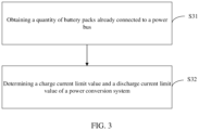
- the method for managing charging and discharging of a parallel-connected battery pack further includes: obtaining a quantity of battery packs already connected to a power bus; and determining a charge current limit value I charge and a discharge current limit value I discharge of a power conversion system.
- the step of managing charging and discharging of the plurality of battery packs based on a comparison result includes: determining, when none of the plurality of battery packs is connected to a power bus, whether a difference between the voltage value of all the battery packs and the reference voltage value is less than a first threshold, and whether a difference between the state of charge of all the battery packs and the reference state of charge is less than a second threshold; and controlling the battery packs to sequentially connect to the power bus if the difference between the voltage value of all the battery packs and the reference voltage value is less than the first threshold, and if the difference between the state of charge of all the battery packs and the reference state of charge is less than the second threshold.
- the step of managing charging and discharging of the plurality of battery packs based on a comparison result further includes: determining, when at least one battery pack is already connected to the power bus and the battery back is in a charging state, whether a difference between the voltage value of battery packs not connected to the power bus and the reference voltage value is within a first range, and whether a difference between the state of charge of the battery packs not connected to the power bus and the reference state of charge is within a second range; and controlling the battery packs to sequentially connect to the power bus if the difference between the voltage value of all the battery packs not connected to the power bus and the reference voltage value is within the first range, and if the difference between the state of charge of all the battery packs not connected to the power bus and the reference state of charge is within the second range.
- the step of managing charging and discharging of the plurality of battery packs based on a comparison result further includes: determining, when at least one battery pack is already connected to the power bus and the battery backs not connected to the power bus are in a discharging state, whether a difference between the reference voltage value and the voltage value of all the battery packs not connected to the power bus is within a third range, and whether a difference between the reference state of charge and the state of charge of all the battery packs not connected to the power bus is within a fourth range; and controlling the battery packs to sequentially connect to the power bus if the difference between the reference voltage value and the voltage value of all the battery packs not connected to the power bus is within the third range, and if the difference between the reference state of charge and the state of charge of all the battery packs not connected to the power bus is within the fourth range.
- the method for managing charging and discharging of a parallel-connected battery pack further includes: receiving fault alarm information when a fault alarm occurs on a battery pack; and controlling all the battery packs to disconnect from the power bus or controlling the faulty battery pack to separately disconnect from the power bus.
- An embodiment of this application further provides an electronic device.
- the electronic device includes:
- the electronic device further includes a plurality of switches in one-to-one correspondence to a plurality of battery packs, and each switch is connected between the battery packs and a power conversion system.
- An embodiment of this application further provides an electrical system.
- the electrical system includes a power conversion system and the electronic device.
- the electronic device further includes a plurality of switches in one-to-one correspondence to a plurality of battery packs. Each switch is connected between the battery packs and the power conversion system.
- the voltage value and the state of charge of a plurality of battery packs are obtained, the voltage value and the state of charge of each of the battery packs is compared with a reference voltage value and a reference state of charge, and the charging and discharging of the plurality of battery packs is managed based on a comparison result.
- the technical solution provided herein can enhance automation of paralleling of battery packs, increase adaptability of a paralleling system, improve paralleling efficiency, further reduce operation and maintenance costs, and improve user experience.
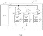
- FIG. 1 is a structural diagram of a paralleling system of a parallel-connected battery pack 10 according to an embodiment of this application.
- An embodiment of this application provides an electrical system.
- the electrical system includes an electronic device 100 and a power conversion system 20.
- the electronic device 100 in the embodiment of this application is electrically connected to the power conversion system 20.
- the electronic device 100 may include the parallel-connected battery pack 10.
- the parallel-connected battery pack 10 may include a plurality of battery packs connected in parallel ( FIG. 1 uses three battery packs 10a, 10b, and 10c as an example, but more or less than three battery packs may be connected in parallel).
- Each battery pack 10a, 10b, 10c includes a positive electrode B+ and a negative electrode B-.
- the positive electrodes B+ of the battery packs 10a ⁇ 10c are connected together to form a positive electrode of the parallel-connected battery pack 10, and the negative electrodes B- of the battery packs 10a ⁇ 10c are connected together to form a negative electrode of the parallel-connected battery pack 10.
- An output of the parallel-connected battery pack 10 is converged to a direct-current input side of the power conversion system 20.
- the negative electrode B- of the battery packs 10a, 10b, and 10c is electrically connected to a power bus P- of the power conversion system 20.
- the positive electrode B+ of the battery packs 10a, 10b, and 10c is electrically connected to a power bus P+ of the power conversion system 20 through a switch K.
- the quantity of switches is identical to the quantity of the battery packs, and the switches are in one-to-one correspondence to the battery packs.
- power lines of each battery pack may be connected in parallel to the power buses P+ and P- through the corresponding switch K.
- each battery pack 10a, 10b, 10c further includes an internal bus interface and an external bus interface.
- the internal bus interface can implement an internal bus communication function
- the external bus interface can implement an external bus communication function. Understandably, the internal bus communication function can implement internal communication between the battery packs 10a ⁇ 10c, and the external bus communication function can implement communication between a master battery pack and the power conversion system 20.
- the internal bus and the external bus may be a controller area network (CAN) communication bus or an RS485 communication bus.
- CAN controller area network
- RS485 RS485 communication bus
- one of the battery packs in the parallel-connected battery pack 10 may be a master battery pack, and remaining battery packs may be slave battery packs.
- a battery management unit may be disposed in each battery pack. Battery cells of each battery pack are managed by a corresponding battery management unit. To be specific, in this embodiment of this application, on/off states of the plurality of switches K may be controlled by the corresponding battery management unit.
- the battery pack 10a is a master battery pack
- the battery packs 10b and 10c are slave battery packs.
- a battery management unit BMU 1 is disposed in the battery pack 10a
- battery management units BMU 2 and BMU 3 are disposed in the battery packs 10b and 10c respectively.
- the battery management unit in the slave battery pack sends data information and status of the corresponding battery pack to the battery management unit in the master battery pack through the internal bus.
- the battery management unit in the master battery pack may aggregate and analyze the data information and status of all the battery management units (including the battery management unit of the master battery pack), calculate a corresponding control parameter, and then control each battery management unit separately through the internal bus, and may, through the external bus, exchange data with the power conversion system 20 and perform operation scheduling.
- FIG. 2 is a flowchart of a method for managing charging and discharging of a parallel-connected battery pack according to an embodiment of this application.
- the method for managing charging and discharging of a parallel-connected battery pack may include the following steps.
- Step S21 Obtaining a voltage value and a state of charge of a plurality of battery packs.
- the battery management unit in each slave battery pack sends data information and status of a corresponding battery pack to a battery management unit in a master battery pack through an internal bus.
- the battery management unit BMU 1 in the battery pack 10a may obtain voltage values and states of charge of the battery packs 10b and 10c through the battery management units BMU 2 and BMU 3.
- state of charge means a ratio of a remaining capacity of a battery to a fully charged capacity of the battery.
- Step S22 Comparing the voltage value and the state of charge of each of the battery packs with a reference voltage value and a reference state of charge.
- a total voltage value of each battery pack needs to be compared with a reference voltage value, and an SOC of each battery pack needs to be compared with a reference SOC.
- the reference voltage value and the reference SOC of the dynamic paralleling of power are calculated by the battery management unit of the master battery pack.
- the reference voltage value may be obtained by: using a minimum value of voltage values of the plurality of battery packs 10a ⁇ 10c as the reference voltage value if none of the plurality of battery packs 10a ⁇ 10c is connected to a power bus.
- the reference SOC may be obtained by: using a minimum value of SOCs of the plurality of battery packs 10a ⁇ 10c as the reference SOC if none of the plurality of battery packs 10a ⁇ 10c is connected to the power bus.
- the reference voltage value may also be obtained by: using a minimum value of voltage values of battery packs already connected to the power bus as the reference voltage value if any battery pack in the plurality of battery packs 10a ⁇ 10c is already connected to the power bus.
- the reference SOC may also be obtained by: using a minimum value of SOCs of battery packs already connected to the power bus as the reference SOC if any battery pack in the plurality of battery packs 10a ⁇ 10c is already connected to the power bus.
- Step S23 Managing charging and discharging of the plurality of battery packs based on a comparison result.
- the battery management unit of the master battery pack compares the voltage value and the SOC of each battery pack with the reference voltage value and the reference SOC to manage charging and discharging of the plurality of battery packs based on a comparison result.
- Dynamic paralleling of power requires coordination of the power conversion system. To be specific, during dynamic paralleling of the battery pack, the power conversion system needs to perform charging or discharging according to a current limit value calculated by the battery management unit of the master battery pack.
- the battery management unit of the master battery pack specifically calculates the charge current limit value and the discharge current limit value by performing the following steps: Step S31: Obtaining a quantity of battery packs already connected to a power bus.
- the battery management unit of the master battery pack obtains the quantity of the battery packs already connected to the power bus.
- Step S32 Determining a charge current limit value and a discharge current limit value of a power conversion system.
- the charge current limit value of the power conversion system is denoted as I charge and the discharge current limit value is denoted as I discharge .
- the battery management unit determines, by performing the following steps and based on a comparison result of the voltage value and the SOC of the battery packs versus the reference voltage value and the reference SOC, how to manage charging and discharging of the plurality of battery packs: Step S41: Determining that none of the plurality of battery packs is connected to the power bus.
- the battery management unit of the master battery pack may determine, based on the data information and status fed back by the battery management unit of each slave battery pack, whether none of the plurality of battery packs is connected to the power bus.
- the battery management unit BMU 1 of the battery pack 10a sends the charge current limit value I charge and the discharge current limit value I discharge to the power conversion system through an external bus, both being 0.
- the reference voltage value of the dynamically paralleled battery pack is the minimum value of the voltage values of the plurality of battery packs
- the reference SOC of the dynamically paralleled battery pack is the minimum value of the SOCs of the plurality of battery packs.
- Step S42 Determining whether a difference between the voltage value of all the battery packs 10a ⁇ 10c and the reference voltage value is less than a first threshold, and whether a difference between the SOC of all the battery packs 10a ⁇ 10c and the reference SOC is less than a second threshold. If the difference is less than the first threshold and the second threshold, the process proceeds to step S43.
- the battery management unit BMU 1 of the battery pack 10a compares the collected total voltage of each battery pack with the reference voltage value, and compares the collected SOC of each battery pack with the reference SOC.
- the battery management unit BMU 1 of the battery pack 10a determines whether the difference between the voltage value of all the battery packs and the reference voltage value is less than the first threshold, and whether the difference between the SOC of all the battery packs and the reference SOC is less than the second threshold.
- Step S43 Controlling the battery packs to sequentially connect to the power bus.
- the battery management unit BMU 1 of the battery pack 10a resets a power paralleling command of each battery pack. Then the battery management units BMU 1, BMU 2, and BMU 3 turn on the switch K, and the plurality of battery packs 10a ⁇ 10c are sequentially connected to the power bus. In this way, paralleling of the power of all the battery packs to the power bus is completed, and a power paralleling completion flag is reset.
- the battery management unit determines, by performing the following steps and based on a comparison result of the voltage value and the SOC of the battery packs versus the reference voltage value and the reference SOC, how to manage charging and discharging of the plurality of battery packs: Step S51: Determining that at least one battery pack is already connected to the power bus and the battery pack is in a charging state.
- the battery management unit of the master battery pack sends a charge current limit value I charge and a discharge current limit value I discharge to the power conversion system 20 through an external bus. Therefore, the power conversion system 20 outputs a charge current and a discharge current according to the corresponding charge current limit value and discharge current limit value.
- Step S52 Determining whether the difference between the voltage value of the battery packs not connected to the power bus and the reference voltage value is within a first range, and whether the difference between the SOC and the reference SOC is within a second range. If the difference is within the first range and the second range, the process proceeds to step S53.
- the battery management unit BMU 1 determines whether the difference between the voltage value of the battery packs 10b and 10c and the reference voltage value is within the first range. In addition, the battery management unit BMU 1 determines whether the difference between the SOC of the battery packs 10b and 10c and the reference SOC is within the second range.
- Step S53 Controlling the battery packs to sequentially connect to the power bus.
- the battery management unit BMU 1 of the master battery pack resets the power paralleling command of each battery pack. Then the battery management units turn on the switch K, and the battery packs not connected to the power bus are sequentially connected to the power bus. In this way, paralleling of the power of all the battery packs to the power bus is completed, and the power paralleling completion flag is reset.
- the battery management unit determines, by performing the following steps and based on a comparison result of the voltage value and the SOC of the battery packs versus the reference voltage value and the reference SOC, how to manage charging and discharging of the plurality of battery packs: Step S61: Determining that at least one battery pack is already connected to the power bus and the battery pack is in a discharging state.
- the battery management unit of the master battery pack sends a charge current limit value I charge and a discharge current limit value I discharge to the power conversion system 20 through an external bus. Therefore, the power conversion system 20 outputs a charge current and a discharge current according to the corresponding charge current limit value and discharge current limit value.
- Step S62 Determining whether the difference between the reference voltage value and the voltage value of all the battery packs not connected to the power bus is within a third range, and whether the difference between the reference SOC and the SOC of all the battery packs not connected to the power bus is within a fourth range. If the difference is within the third range and the fourth range, the process proceeds to step S63.
- the battery management unit BMU 1 determines whether the difference between the reference voltage value and the voltage value of the battery packs 10b and 10c is within the third range. In addition, the battery management unit BMU 1 determines whether the difference between the reference SOC and the SOC of the battery packs 10b and 10c is within the fourth range.
- Step S63 Controlling the battery packs to sequentially connect to the power bus.
- the battery management unit BMU 1 of the master battery pack resets the power paralleling command of each battery pack. Then the battery management units turn on the switch K, and the battery packs not connected to the power bus are sequentially connected to the power bus. In this way, paralleling of the power of all the battery packs to the power bus is completed, and the power paralleling completion flag is reset.
- the battery management unit of the master battery pack calculates and updates the reference voltage value and the reference SOC in real time. If the voltage value and the SOC of the battery packs not connected to the power bus satisfy power paralleling conditions one by one during the charging or discharging, the battery packs will be connected to the power bus one by one, and the power paralleling completion flag of the battery packs will be reset one by one. As the quantity of the paralleled battery packs increases, the charge current limit value I charge and the discharge current limit value I discharge is calculated and updated in real time until all the battery packs have completed paralleling.
- the battery packs reset the power paralleling completion flag
- the master battery pack resets a main flag of power paralleling completion, and stops calculating the reference voltage value and the reference SOC.
- the calculation method of charge current limit value I charge and the discharge current limit value I discharge is changed from a current limiting method of power paralleling mode to a charge and discharge current limit value method of a normal operation mode of the energy storage system. That is, all the battery packs of the energy storage system exit the power paralleling mode.
- the power conversion system receives the main flag of power paralleling completion as well as the charge and discharge current limit values of the normal operation mode from the battery management unit of the master battery pack, and the power conversion system and the energy storage system enter the normal operation mode synchronously.
- the battery management unit of each battery pack (such as BMU 2 in the battery pack 10b) raises a fault alarm
- the battery management unit of the master battery pack (such as BMU 1 in the battery pack 10a) receives fault alarm information of each battery pack, and then controls all the battery packs to disconnect from the power bus, or controls the faulty battery pack to separately disconnect from the power bus.
- the disconnected battery pack removes the power paralleling completion flag
- the battery management BMU 1 in the master battery pack removes the power paralleling completion flag
- the energy storage system exits the normal operation mode and re-enters a power paralleling determining mode.
- FIG. 7 is a schematic diagram of a system 30 for managing charging and discharging of a parallel-connected battery pack according to an embodiment of this application.
- the system 30 for managing charging and discharging of a parallel-connected battery pack may be divided into one or more modules.
- the one or more modules are stored in the battery management unit BMU 1, and are managed by the battery management unit BMU 1.
- the battery management unit BMU 1 implements the steps described in the embodiment of the method for managing charging and discharging of a parallel-connected battery pack to implement this application.
- the one or more modules may be a series of computer program instruction segments capable of implementing specific functions.
- the instruction segments are used to describe a process of implementing the system 30 for managing charging and discharging of a parallel-connected battery pack in the electronic device 100.
- the system 30 for managing charging and discharging of a parallel-connected battery pack may be divided into an obtaining module 301, a comparison module 302, and a control module 303 in FIG. 7 .
- the obtaining module 301 is configured to obtain a voltage value and an SOC of a plurality of battery packs.
- the comparison module 302 is configured to compare the voltage value and the SOC of each of the battery packs with a reference voltage value and a reference SOC.
- the control module 303 is configured to manage charging and discharging of the plurality of battery packs based on a comparison result.
- the system for managing charging and discharging of a parallel-connected battery pack 30 can manage charging and discharging of the battery packs 10a ⁇ 10c, enhance automation of paralleling of the battery packs, increase adaptability of a paralleling system, improve paralleling efficiency, further reduce operation and maintenance costs, and improve user experience. Details may be obtained by referring to the embodiment of the method for managing charging and discharging of a parallel-connected battery pack, and are omitted here.
- the division into the modules is a logical function division, and may be in other division forms in actual implementation.
- function modules in each embodiment of this application may be integrated into one processing unit, or each module may exist physically alone, or two or more modules may be integrated into one unit.
- the integrated module may be implemented in form of hardware, or may be implemented in form of hardware plus a software function module.
Landscapes
- Engineering & Computer Science (AREA)
- Power Engineering (AREA)
- Physics & Mathematics (AREA)
- General Physics & Mathematics (AREA)
- Chemical Kinetics & Catalysis (AREA)
- Chemical & Material Sciences (AREA)
- Manufacturing & Machinery (AREA)
- Electrochemistry (AREA)
- General Chemical & Material Sciences (AREA)
- Charge And Discharge Circuits For Batteries Or The Like (AREA)
- Secondary Cells (AREA)
- Health & Medical Sciences (AREA)
- General Health & Medical Sciences (AREA)
- Medical Informatics (AREA)
Abstract
Description
- This application relates to the technical field of a power supply, and in particular, to a method for managing charging and discharging of a parallel-connected battery pack, an electronic device, and an electrical system.
- To meet increased user requirements for power and endurance time of an energy storage battery, a single-battery-pack solution requires a higher energy density and a higher capacity of a battery cell of the battery pack, thereby increasing a volume and a weight of the battery pack and increasing costs of research and development, manufacturing, transportation, and installation of the battery pack. However, a parallel-connected battery pack solution, viewed from a research and development perspective, requires merely design of a low-capacity solution, thereby reducing research and development costs and safety certification costs for developers. A key to a parallel-connected battery pack is that a master battery pack needs to monitor status information of each slave battery pack in real time. When a battery pack is faulty, the master battery pack feeds back fault information to a power conversion system (PCS) in time, and the PCS can immediately reduce power or cut off load operation to ensure safe operation of the parallel-connected battery pack.
- An existing technology of paralleling an energy storage system has the following problems: (1) prerequisites of paralleling battery packs are that the battery packs stand statically and have consistent voltages, and the voltages of the battery packs have to be manually adjusted during charging and discharging, consequently increasing complexity and costs of mounting and debugging; and (2) in a case that the battery packs are connected in parallel when being charged or discharged, voltage is used as a unique basis for paralleling, consequently increasing burnout risks caused by a too high cross current in a power loop of the parallel-connected battery pack.
- Solutions available in the prior art to such problems include: (1) before the battery packs are paralleled, a total voltage of each battery pack is manually adjusted, the battery packs are charged or discharged until the total voltage of each battery pack reaches a fixed voltage value, and the battery packs are paralleled after total voltages of all the battery packs have been adjusted properly; and (2) the battery packs are paralleled during charging or discharging, but a parameter used as a basis for paralleling is merely the voltage of each battery pack, and a charge or discharge current during the paralleling depends on a next-level load; and, when the voltage of a battery pack first incorporated into the power loop rises or falls to a value consistent with the voltage of an unincorporated battery pack during the charging or discharging, the unincorporated battery pack is connected to the power loop in parallel.
- However, the solutions in the prior art have the following disadvantages: (1) in solution (1), the voltage of the battery pack needs to be adjusted manually, and the parallel connecting of the battery packs is not smart enough but increases the complexity and costs of mounting and debugging; and (2) in solution (2), merely a single parameter is used as a basis for the parallel connecting of battery pack, and the charge current and the discharge current are not limited. Consequently, the voltage is consistent between the parallel-connected battery packs but an actual capacity differs sharply, the cross current between the parallel-connected battery packs is too high, and the battery cells of the battery packs, the power loop, and devices are likely to be damaged by the too high cross current.
- In view of the foregoing situation, it is necessary to provide a method for managing charging and discharging of a parallel-connected battery pack, an electronic device, and an electrical system to enhance automation of paralleling of the battery packs, increase adaptability of a paralleling system, improve paralleling efficiency, further reduce operation and maintenance costs, and improve user experience.
- An embodiment of this application provides a method for managing charging and discharging of a parallel-connected battery pack. The method for managing charging and discharging of a parallel-connected battery pack includes: obtaining a voltage value and a state of charge of a plurality of battery packs; comparing the voltage value and the state of charge of each of the battery packs with a reference voltage value and a reference state of charge; and managing charging and discharging of the plurality of battery packs based on a comparison result.
- According to some embodiments of this application, the reference voltage value may be obtained by: using a minimum value of voltage values of the plurality of battery packs as the reference voltage value when none of the plurality of battery packs is connected to a power bus.
- According to some embodiments of this application, the reference state of charge may be obtained by: using a minimum value of states of charge of the plurality of battery packs as the reference state of charge when none of the plurality of battery packs is connected to a power bus.
- According to some embodiments of this application, the reference voltage value may also be obtained by: using a minimum value of voltage values of battery packs already connected to a power bus as the reference voltage value when a battery pack is already connected to the power bus.
- According to some embodiments of this application, the reference state of charge may also be obtained by: using a minimum value of states of charge of battery packs already connected to a power bus as the reference state of charge when a battery pack is already connected to the power bus.
- According to some embodiments of this application, the method for managing charging and discharging of a parallel-connected battery pack further includes: obtaining a quantity of battery packs already connected to a power bus; and determining a charge current limit value Icharge and a discharge current limit value Idischarge of a power conversion system.
- According to some embodiments of this application, the charge current limit value Icharge satisfies the following formula:

- According to some embodiments of this application, the discharge current limit value Idischarge satisfies the following formula:

- According to some embodiments of this application, the step of managing charging and discharging of the plurality of battery packs based on a comparison result includes: determining, when none of the plurality of battery packs is connected to a power bus, whether a difference between the voltage value of all the battery packs and the reference voltage value is less than a first threshold, and whether a difference between the state of charge of all the battery packs and the reference state of charge is less than a second threshold; and controlling the battery packs to sequentially connect to the power bus if the difference between the voltage value of all the battery packs and the reference voltage value is less than the first threshold, and if the difference between the state of charge of all the battery packs and the reference state of charge is less than the second threshold.
- According to some embodiments of this application, the step of managing charging and discharging of the plurality of battery packs based on a comparison result further includes: determining, when at least one battery pack is already connected to the power bus and the battery back is in a charging state, whether a difference between the voltage value of battery packs not connected to the power bus and the reference voltage value is within a first range, and whether a difference between the state of charge of the battery packs not connected to the power bus and the reference state of charge is within a second range; and controlling the battery packs to sequentially connect to the power bus if the difference between the voltage value of all the battery packs not connected to the power bus and the reference voltage value is within the first range, and if the difference between the state of charge of all the battery packs not connected to the power bus and the reference state of charge is within the second range.
- According to some embodiments of this application, the step of managing charging and discharging of the plurality of battery packs based on a comparison result further includes: determining, when at least one battery pack is already connected to the power bus and the battery backs not connected to the power bus are in a discharging state, whether a difference between the reference voltage value and the voltage value of all the battery packs not connected to the power bus is within a third range, and whether a difference between the reference state of charge and the state of charge of all the battery packs not connected to the power bus is within a fourth range; and controlling the battery packs to sequentially connect to the power bus if the difference between the reference voltage value and the voltage value of all the battery packs not connected to the power bus is within the third range, and if the difference between the reference state of charge and the state of charge of all the battery packs not connected to the power bus is within the fourth range.
- According to some embodiments of this application, the method for managing charging and discharging of a parallel-connected battery pack further includes: receiving fault alarm information when a fault alarm occurs on a battery pack; and controlling all the battery packs to disconnect from the power bus or controlling the faulty battery pack to separately disconnect from the power bus.
- An embodiment of this application further provides an electronic device. The electronic device includes:
- a plurality of battery packs; and
- a battery management unit, configured to perform the foregoing method for managing charging and discharging.
- According to some embodiments of this application, the electronic device further includes a plurality of switches in one-to-one correspondence to a plurality of battery packs, and each switch is connected between the battery packs and a power conversion system.
- An embodiment of this application further provides an electrical system. The electrical system includes a power conversion system and the electronic device. The electronic device further includes a plurality of switches in one-to-one correspondence to a plurality of battery packs. Each switch is connected between the battery packs and the power conversion system.
- In the method for managing charging and discharging of a parallel-connected battery pack, the electronic device, and the electrical system according to the embodiments of this application, the voltage value and the state of charge of a plurality of battery packs are obtained, the voltage value and the state of charge of each of the battery packs is compared with a reference voltage value and a reference state of charge, and the charging and discharging of the plurality of battery packs is managed based on a comparison result. In this way, the technical solution provided herein can enhance automation of paralleling of battery packs, increase adaptability of a paralleling system, improve paralleling efficiency, further reduce operation and maintenance costs, and improve user experience.
-
-
FIG. 1 is a structural diagram of a paralleling system of a parallel-connected battery pack according to an embodiment of this application; -
FIG. 2 is a flowchart of a method for managing charging and discharging of a parallel-connected battery pack according to an embodiment of this application; -
FIG. 3 is a flowchart of a method for managing charging and discharging of a parallel-connected battery pack according to another embodiment of this application; -
FIG. 4 is a flowchart of a method for managing charging and discharging of a parallel-connected battery pack according to another embodiment of this application; -
FIG. 5 is a flowchart of a method for managing charging and discharging of a parallel-connected battery pack according to another embodiment of this application; -
FIG. 6 is a flowchart of a method for managing charging and discharging of a parallel-connected battery pack according to another embodiment of this application; -
FIG. 7 is a modular diagram of a system for managing charging and discharging of a parallel-connected battery pack according to an embodiment of this application. - Reference numerals:
-
Electronic device 100 - Parallel-connected
battery pack 10 -
Battery packs -
Power conversion system 20 - System for managing charging and discharging of a parallel-connected
battery pack 30 - Switch K
- Battery management units BMU 1, BMU 2, BMU 3
- Obtaining
module 301 -
Comparison module 302 -
Control module 303 - This application is described in further detail below with reference to specific embodiments and the drawings.
- The following clearly and fully describes the technical solutions in the embodiments of this application with reference to the drawings hereof. Apparently, the described embodiments are merely a part of but not all of the embodiments of this application.
- Referring to
FIG. 1, FIG. 1 is a structural diagram of a paralleling system of a parallel-connectedbattery pack 10 according to an embodiment of this application. - An embodiment of this application provides an electrical system. The electrical system includes an
electronic device 100 and apower conversion system 20. Theelectronic device 100 in the embodiment of this application is electrically connected to thepower conversion system 20. Theelectronic device 100 may include the parallel-connectedbattery pack 10. - Specifically, the parallel-connected
battery pack 10 may include a plurality of battery packs connected in parallel (FIG. 1 uses threebattery packs - Each
battery pack battery pack 10, and the negative electrodes B- of the battery packs 10a~10c are connected together to form a negative electrode of the parallel-connectedbattery pack 10. An output of the parallel-connectedbattery pack 10 is converged to a direct-current input side of thepower conversion system 20. Specifically, the negative electrode B- of the battery packs 10a, 10b, and 10c is electrically connected to a power bus P- of thepower conversion system 20. The positive electrode B+ of the battery packs 10a, 10b, and 10c is electrically connected to a power bus P+ of thepower conversion system 20 through a switch K. In this embodiment of this application, the quantity of switches is identical to the quantity of the battery packs, and the switches are in one-to-one correspondence to the battery packs. To be specific, power lines of each battery pack may be connected in parallel to the power buses P+ and P- through the corresponding switch K. - In an embodiment of this application, each
battery pack power conversion system 20. - In a preferred embodiment, the internal bus and the external bus may be a controller area network (CAN) communication bus or an RS485 communication bus.
- In an embodiment of this application, one of the battery packs in the parallel-connected
battery pack 10 may be a master battery pack, and remaining battery packs may be slave battery packs. - Understandably, a battery management unit may be disposed in each battery pack. Battery cells of each battery pack are managed by a corresponding battery management unit. To be specific, in this embodiment of this application, on/off states of the plurality of switches K may be controlled by the corresponding battery management unit. Specifically, in this embodiment of this application, the battery pack 10a is a master battery pack, and the battery packs 10b and 10c are slave battery packs. A battery management unit BMU 1 is disposed in the battery pack 10a, and battery management units BMU 2 and BMU 3 are disposed in the battery packs 10b and 10c respectively.
- Subsequently, the battery management unit in the slave battery pack sends data information and status of the corresponding battery pack to the battery management unit in the master battery pack through the internal bus. In this way, the battery management unit in the master battery pack may aggregate and analyze the data information and status of all the battery management units (including the battery management unit of the master battery pack), calculate a corresponding control parameter, and then control each battery management unit separately through the internal bus, and may, through the external bus, exchange data with the
power conversion system 20 and perform operation scheduling. - Referring to
FIG. 2, FIG. 2 is a flowchart of a method for managing charging and discharging of a parallel-connected battery pack according to an embodiment of this application. The method for managing charging and discharging of a parallel-connected battery pack may include the following steps. - Step S21: Obtaining a voltage value and a state of charge of a plurality of battery packs.
- In this embodiment of this application, the battery management unit in each slave battery pack sends data information and status of a corresponding battery pack to a battery management unit in a master battery pack through an internal bus. For example, the battery management unit BMU 1 in the battery pack 10a may obtain voltage values and states of charge of the battery packs 10b and 10c through the battery management units BMU 2 and BMU 3.
- Understandably, the state of charge (state of charge, SOC) means a ratio of a remaining capacity of a battery to a fully charged capacity of the battery.
- Step S22: Comparing the voltage value and the state of charge of each of the battery packs with a reference voltage value and a reference state of charge.
- Specifically, when performing dynamic paralleling of power, a total voltage value of each battery pack needs to be compared with a reference voltage value, and an SOC of each battery pack needs to be compared with a reference SOC.
- The reference voltage value and the reference SOC of the dynamic paralleling of power are calculated by the battery management unit of the master battery pack.
- In a preferred embodiment, the reference voltage value may be obtained by: using a minimum value of voltage values of the plurality of battery packs 10a~10c as the reference voltage value if none of the plurality of battery packs 10a~10c is connected to a power bus.
- In a preferred embodiment, the reference SOC may be obtained by: using a minimum value of SOCs of the plurality of battery packs 10a~10c as the reference SOC if none of the plurality of battery packs 10a~10c is connected to the power bus.
- According to another preferred embodiment of this application, the reference voltage value may also be obtained by: using a minimum value of voltage values of battery packs already connected to the power bus as the reference voltage value if any battery pack in the plurality of battery packs 10a~10c is already connected to the power bus.
- According to another preferred embodiment of this application, the reference SOC may also be obtained by: using a minimum value of SOCs of battery packs already connected to the power bus as the reference SOC if any battery pack in the plurality of battery packs 10a~10c is already connected to the power bus.
- Step S23: Managing charging and discharging of the plurality of battery packs based on a comparison result.
- In this embodiment of this application, after the reference voltage value and the reference SOC are determined, the battery management unit of the master battery pack compares the voltage value and the SOC of each battery pack with the reference voltage value and the reference SOC to manage charging and discharging of the plurality of battery packs based on a comparison result.
- Dynamic paralleling of power requires coordination of the power conversion system. To be specific, during dynamic paralleling of the battery pack, the power conversion system needs to perform charging or discharging according to a current limit value calculated by the battery management unit of the master battery pack.
- In a preferred embodiment, referring to
FIG. 3 , the battery management unit of the master battery pack specifically calculates the charge current limit value and the discharge current limit value by performing the following steps:
Step S31: Obtaining a quantity of battery packs already connected to a power bus. - In this embodiment of this application, the battery management unit of the master battery pack obtains the quantity of the battery packs already connected to the power bus.
- Step S32: Determining a charge current limit value and a discharge current limit value of a power conversion system.
- In this embodiment of this application, the charge current limit value of the power conversion system is denoted as Icharge and the discharge current limit value is denoted as Idischarge.
- Specifically, the charge current limit value Icharge satisfies the following formula:

- Further, the discharge current limit value Idischarge satisfies the following formula:

- In this embodiment of this application, when the power of no battery pack is connected onto the power bus, that is, when Pm = 0, it can be deduced from the foregoing formula that the charge current limit value Icharge of the power conversion system and the discharge current limit value Idischarge are 0.
- In a preferred embodiment, referring to
FIG. 4 , the battery management unit determines, by performing the following steps and based on a comparison result of the voltage value and the SOC of the battery packs versus the reference voltage value and the reference SOC, how to manage charging and discharging of the plurality of battery packs:
Step S41: Determining that none of the plurality of battery packs is connected to the power bus. - In this embodiment of this application, the battery management unit of the master battery pack may determine, based on the data information and status fed back by the battery management unit of each slave battery pack, whether none of the plurality of battery packs is connected to the power bus.
- Specifically, if it is determined that the power of no battery pack is connected to the power bus, that is, if none of the battery packs 10a, 10b, and 10c in this embodiment of this application is connected to the power bus, the battery management unit BMU 1 of the battery pack 10a sends the charge current limit value Icharge and the discharge current limit value Idischarge to the power conversion system through an external bus, both being 0. In this case, it is determined that the reference voltage value of the dynamically paralleled battery pack is the minimum value of the voltage values of the plurality of battery packs, and the reference SOC of the dynamically paralleled battery pack is the minimum value of the SOCs of the plurality of battery packs.
- Step S42: Determining whether a difference between the voltage value of all the battery packs 10a~10c and the reference voltage value is less than a first threshold, and whether a difference between the SOC of all the battery packs 10a~10c and the reference SOC is less than a second threshold. If the difference is less than the first threshold and the second threshold, the process proceeds to step S43.
- In this embodiment of this application, the battery management unit BMU 1 of the battery pack 10a compares the collected total voltage of each battery pack with the reference voltage value, and compares the collected SOC of each battery pack with the reference SOC.
- Subsequently, the battery management unit BMU 1 of the battery pack 10a determines whether the difference between the voltage value of all the battery packs and the reference voltage value is less than the first threshold, and whether the difference between the SOC of all the battery packs and the reference SOC is less than the second threshold.
- Step S43: Controlling the battery packs to sequentially connect to the power bus.
- In this embodiment of this application, if the difference between the voltage value of all the battery packs 10a~10c and the reference voltage value is less than the first threshold, and if the difference between the SOC of all the battery packs 10a~10c and the reference SOC is less than the second threshold, the battery management unit BMU 1 of the battery pack 10a resets a power paralleling command of each battery pack. Then the battery management units BMU 1, BMU 2, and BMU 3 turn on the switch K, and the plurality of battery packs 10a~10c are sequentially connected to the power bus. In this way, paralleling of the power of all the battery packs to the power bus is completed, and a power paralleling completion flag is reset.
- In another preferred embodiment, referring to
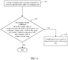
FIG. 5 , the battery management unit determines, by performing the following steps and based on a comparison result of the voltage value and the SOC of the battery packs versus the reference voltage value and the reference SOC, how to manage charging and discharging of the plurality of battery packs:
Step S51: Determining that at least one battery pack is already connected to the power bus and the battery pack is in a charging state. - In this embodiment of this application, if it is determined that at least one battery pack is already connected to the power bus and the battery pack is in the charging state, the battery management unit of the master battery pack sends a charge current limit value Icharge and a discharge current limit value Idischarge to the
power conversion system 20 through an external bus. Therefore, thepower conversion system 20 outputs a charge current and a discharge current according to the corresponding charge current limit value and discharge current limit value. - Step S52: Determining whether the difference between the voltage value of the battery packs not connected to the power bus and the reference voltage value is within a first range, and whether the difference between the SOC and the reference SOC is within a second range. If the difference is within the first range and the second range, the process proceeds to step S53.
- For example, in this embodiment of this application, when the battery pack 10a is already connected to the power bus but the battery packs 10b and 10c are not connected to the power bus, the battery management unit BMU 1 determines whether the difference between the voltage value of the battery packs 10b and 10c and the reference voltage value is within the first range. In addition, the battery management unit BMU 1 determines whether the difference between the SOC of the battery packs 10b and 10c and the reference SOC is within the second range.
- Step S53: Controlling the battery packs to sequentially connect to the power bus.
- In this embodiment of this application, if the difference between the voltage value of the battery packs not connected to the power bus and the reference voltage value is within the first range, and if the difference between the SOC and the reference SOC is within the second range, the battery management unit BMU 1 of the master battery pack resets the power paralleling command of each battery pack. Then the battery management units turn on the switch K, and the battery packs not connected to the power bus are sequentially connected to the power bus. In this way, paralleling of the power of all the battery packs to the power bus is completed, and the power paralleling completion flag is reset.
- In another preferred embodiment, referring to
FIG. 6 , the battery management unit determines, by performing the following steps and based on a comparison result of the voltage value and the SOC of the battery packs versus the reference voltage value and the reference SOC, how to manage charging and discharging of the plurality of battery packs:
Step S61: Determining that at least one battery pack is already connected to the power bus and the battery pack is in a discharging state. - In this embodiment of this application, if it is determined that at least one battery pack is already connected to the power bus and the battery pack is in the discharging state, the battery management unit of the master battery pack sends a charge current limit value Icharge and a discharge current limit value Idischarge to the
power conversion system 20 through an external bus. Therefore, thepower conversion system 20 outputs a charge current and a discharge current according to the corresponding charge current limit value and discharge current limit value. - Step S62: Determining whether the difference between the reference voltage value and the voltage value of all the battery packs not connected to the power bus is within a third range, and whether the difference between the reference SOC and the SOC of all the battery packs not connected to the power bus is within a fourth range. If the difference is within the third range and the fourth range, the process proceeds to step S63.
- For example, in this embodiment of this application, when the battery pack 10a is already connected to the power bus but the battery packs 10b and 10c are not connected to the power bus, the battery management unit BMU 1 determines whether the difference between the reference voltage value and the voltage value of the battery packs 10b and 10c is within the third range. In addition, the battery management unit BMU 1 determines whether the difference between the reference SOC and the SOC of the battery packs 10b and 10c is within the fourth range.
- Step S63: Controlling the battery packs to sequentially connect to the power bus.
- In this embodiment of this application, if the difference between the reference voltage value and the voltage value of all the battery packs not connected to the power bus is within the third range, and if the difference between the reference SOC and the SOC of all the battery packs not connected to the power bus is within the fourth range, the battery management unit BMU 1 of the master battery pack resets the power paralleling command of each battery pack. Then the battery management units turn on the switch K, and the battery packs not connected to the power bus are sequentially connected to the power bus. In this way, paralleling of the power of all the battery packs to the power bus is completed, and the power paralleling completion flag is reset.
- Understandably, as the charging or discharging of the
power conversion system 20 continues, the battery management unit of the master battery pack calculates and updates the reference voltage value and the reference SOC in real time. If the voltage value and the SOC of the battery packs not connected to the power bus satisfy power paralleling conditions one by one during the charging or discharging, the battery packs will be connected to the power bus one by one, and the power paralleling completion flag of the battery packs will be reset one by one. As the quantity of the paralleled battery packs increases, the charge current limit value Icharge and the discharge current limit value Idischarge is calculated and updated in real time until all the battery packs have completed paralleling. In this case, the battery packs reset the power paralleling completion flag, and the master battery pack resets a main flag of power paralleling completion, and stops calculating the reference voltage value and the reference SOC. The calculation method of charge current limit value Icharge and the discharge current limit value Idischarge is changed from a current limiting method of power paralleling mode to a charge and discharge current limit value method of a normal operation mode of the energy storage system. That is, all the battery packs of the energy storage system exit the power paralleling mode. The power conversion system receives the main flag of power paralleling completion as well as the charge and discharge current limit values of the normal operation mode from the battery management unit of the master battery pack, and the power conversion system and the energy storage system enter the normal operation mode synchronously. - In this embodiment of this application, when the battery management unit of each battery pack (such as BMU 2 in the
battery pack 10b) raises a fault alarm, the battery management unit of the master battery pack (such as BMU 1 in the battery pack 10a) receives fault alarm information of each battery pack, and then controls all the battery packs to disconnect from the power bus, or controls the faulty battery pack to separately disconnect from the power bus. The disconnected battery pack removes the power paralleling completion flag, the battery management BMU 1 in the master battery pack removes the power paralleling completion flag, and the energy storage system exits the normal operation mode and re-enters a power paralleling determining mode. -
FIG. 7 is a schematic diagram of asystem 30 for managing charging and discharging of a parallel-connected battery pack according to an embodiment of this application. In this embodiment, thesystem 30 for managing charging and discharging of a parallel-connected battery pack may be divided into one or more modules. The one or more modules are stored in the battery management unit BMU 1, and are managed by the battery management unit BMU 1. When executing a computer program, the battery management unit BMU 1 implements the steps described in the embodiment of the method for managing charging and discharging of a parallel-connected battery pack to implement this application. The one or more modules may be a series of computer program instruction segments capable of implementing specific functions. The instruction segments are used to describe a process of implementing thesystem 30 for managing charging and discharging of a parallel-connected battery pack in theelectronic device 100. For example, thesystem 30 for managing charging and discharging of a parallel-connected battery pack may be divided into an obtainingmodule 301, acomparison module 302, and acontrol module 303 inFIG. 7 . - The obtaining
module 301 is configured to obtain a voltage value and an SOC of a plurality of battery packs. - The
comparison module 302 is configured to compare the voltage value and the SOC of each of the battery packs with a reference voltage value and a reference SOC. - The
control module 303 is configured to manage charging and discharging of the plurality of battery packs based on a comparison result. - The system for managing charging and discharging of a parallel-connected
battery pack 30 can manage charging and discharging of the battery packs 10a~10c, enhance automation of paralleling of the battery packs, increase adaptability of a paralleling system, improve paralleling efficiency, further reduce operation and maintenance costs, and improve user experience. Details may be obtained by referring to the embodiment of the method for managing charging and discharging of a parallel-connected battery pack, and are omitted here. - Understandably, the division into the modules is a logical function division, and may be in other division forms in actual implementation. In addition, function modules in each embodiment of this application may be integrated into one processing unit, or each module may exist physically alone, or two or more modules may be integrated into one unit. The integrated module may be implemented in form of hardware, or may be implemented in form of hardware plus a software function module.
- A person of ordinary skill in the art understands that the foregoing embodiments are merely intended to illustrate this application, but not intended as a limitation on this application. All appropriate modifications and changes made to the embodiments without departing from the spirit and scope of this application fall within the protection scope of this application.
Claims (14)
- A method for managing charging and discharging of a parallel-connected battery pack, wherein the method for managing charging and discharging of a parallel-connected battery pack comprises:obtaining a voltage value and a state of charge of a plurality of battery packs;comparing the voltage value and the state of charge of each of the battery packs with a reference voltage value and a reference state of charge; andmanaging charging and discharging of the plurality of battery packs based on a comparison result.
- The method for managing charging and discharging of a parallel-connected battery pack according to claim 1, wherein the reference voltage value is obtained by:
using a minimum value of voltage values of the plurality of battery packs as the reference voltage value when none of the plurality of battery packs is connected to a power bus. - The method for managing charging and discharging of a parallel-connected battery pack according to claim 1, wherein the reference state of charge is obtained by:
using a minimum value of states of charge of the plurality of battery packs as the reference state of charge when none of the plurality of battery packs is connected to a power bus. - The method for managing charging and discharging of a parallel-connected battery pack according to claim 1, wherein the reference voltage value is obtained by:
using a minimum value of voltage values of battery packs already connected to a power bus as the reference voltage value when a battery pack is already connected to the power bus. - The method for managing charging and discharging of a parallel-connected battery pack according to claim 1, wherein the reference state of charge is obtained by:
using a minimum value of states of charge of battery packs already connected to a power bus as the reference state of charge when a battery pack is already connected to the power bus. - The method for managing charging and discharging of a parallel-connected battery pack according to claim 1, wherein the method for managing charging and discharging of a parallel-connected battery pack further comprises:obtaining a quantity of battery packs already connected to a power bus; anddetermining a charge current limit value Icharge and a discharge current limit value Idischarge of a power conversion system.
- The method for managing charging and discharging of a parallel-connected battery pack according to claim 6, wherein the charge current limit value Icharge satisfies the following formula:

- The method for managing charging and discharging of a parallel-connected battery pack according to claim 6, wherein the discharge current limit value Idischarge satisfies the following formula:

- The method for managing charging and discharging of a parallel-connected battery pack according to claim 1, wherein the step of managing charging and discharging of the plurality of battery packs based on a comparison result comprises:determining, when none of the plurality of battery packs is connected to a power bus, whether a difference between the voltage value of all the battery packs and the reference voltage value is less than a first threshold, and whether a difference between the state of charge of all the battery packs and the reference state of charge is less than a second threshold; andcontrolling the battery packs to sequentially connect to the power bus if the difference between the voltage value of all the battery packs and the reference voltage value is less than the first threshold, and if the difference between the state of charge of all the battery packs and the reference state of charge is less than the second threshold.
- The method for managing charging and discharging of a parallel-connected battery pack according to claim 9, wherein the step of managing charging and discharging of the plurality of battery packs based on a comparison result comprises:determining, when at least one battery pack is already connected to the power bus and the battery back is in a charging state, whether a difference between the voltage value of battery packs not connected to the power bus and the reference voltage value is within a first range, and whether a difference between the state of charge of the battery packs not connected to the power bus and the reference state of charge is within a second range; andcontrolling the battery packs to sequentially connect to the power bus if the difference between the voltage value of all the battery packs not connected to the power bus and the reference voltage value is within the first range, and if the difference between the state of charge of all the battery packs not connected to the power bus and the reference state of charge is within the second range.
- The method for managing charging and discharging of a parallel-connected battery pack according to claim 10, wherein the step of managing charging and discharging of the plurality of battery packs based on a comparison result comprises:determining, when at least one battery pack is already connected to the power bus and the battery backs not connected to the power bus are in a discharging state, whether a difference between the reference voltage value and the voltage value of all the battery packs not connected to the power bus is within a third range, and whether a difference between the reference state of charge and the state of charge of all the battery packs not connected to the power bus is within a fourth range; andcontrolling the battery packs to sequentially connect to the power bus if the difference between the reference voltage value and the voltage value of all the battery packs not connected to the power bus is within the third range, and if the difference between the reference state of charge and the state of charge of all the battery packs not connected to the power bus is within the fourth range.
- The method for managing charging and discharging of a parallel-connected battery pack according to claim 11, wherein the method for managing charging and discharging of a parallel-connected battery pack further comprises:receiving fault alarm information when a fault alarm occurs on a battery pack; andcontrolling all the battery packs to disconnect from the power bus or controlling the faulty battery pack to separately disconnect from the power bus.
- An electronic device, wherein the electronic device comprises:a plurality of battery packs; anda battery management unit, configured to perform the method for managing charging and discharging according to any one of claims 1 to 12.
- An electrical system, wherein the electrical system comprises a power conversion system and the electronic device according to claim 13, and the electronic device further comprises a plurality of switches in one-to-one correspondence to a plurality of battery packs, and each switch is connected between the battery packs and the power conversion system.
Applications Claiming Priority (2)
| Application Number | Priority Date | Filing Date | Title |
|---|---|---|---|
| CN202010230929.9A CN111431228B (en) | 2020-03-27 | 2020-03-27 | Parallel battery charge and discharge management method and electronic device |
| PCT/CN2021/076382 WO2021190196A1 (en) | 2020-03-27 | 2021-02-09 | Charging and discharging management method for parallel battery packs, electronic device, and electrical system |
Publications (2)
| Publication Number | Publication Date |
|---|---|
| EP4131706A1 true EP4131706A1 (en) | 2023-02-08 |
| EP4131706A4 EP4131706A4 (en) | 2023-11-22 |
Family
ID=71555516
Family Applications (1)
| Application Number | Title | Priority Date | Filing Date |
|---|---|---|---|
| EP21776075.0A Pending EP4131706A4 (en) | 2020-03-27 | 2021-02-09 | CHARGING AND DISCHARGE MANAGEMENT METHOD FOR PARALLEL BATTERY PACKS, ELECTRONIC DEVICE AND ELECTRICAL SYSTEM |
Country Status (7)
| Country | Link |
|---|---|
| US (1) | US11949273B2 (en) |
| EP (1) | EP4131706A4 (en) |
| JP (1) | JP7244635B2 (en) |
| KR (1) | KR102659479B1 (en) |
| CN (1) | CN111431228B (en) |
| AU (1) | AU2021202731B2 (en) |
| WO (1) | WO2021190196A1 (en) |
Cited By (3)
| Publication number | Priority date | Publication date | Assignee | Title |
|---|---|---|---|---|
| EP4439916A1 (en) * | 2023-03-31 | 2024-10-02 | Sungrow Power Supply Co., Ltd. | Method for connecting battery rack in parallel, battery management system, device and storage medium |
| EP4224662A4 (en) * | 2020-09-29 | 2024-11-20 | Panasonic Intellectual Property Management Co., Ltd. | POWER MANAGEMENT DEVICE AND POWER SUPPLY SYSTEM |
| EP4629475A1 (en) * | 2024-03-29 | 2025-10-08 | Xiamen Ampack Technology Limited | Battery parallel system and battery parallel-connection method |
Families Citing this family (21)
| Publication number | Priority date | Publication date | Assignee | Title |
|---|---|---|---|---|
| JP7191873B2 (en) * | 2020-01-17 | 2022-12-19 | 株式会社東芝 | Charge/discharge control device, charge/discharge system, charge/discharge control method, and charge/discharge control program |
| CN111431228B (en) * | 2020-03-27 | 2023-06-20 | 东莞新能安科技有限公司 | Parallel battery charge and discharge management method and electronic device |
| JP7377860B2 (en) * | 2020-06-17 | 2023-11-10 | 東莞新能安科技有限公司 | Battery protection circuit, battery management system, battery device and its control method |
| US20220029431A1 (en) * | 2020-07-23 | 2022-01-27 | Aurora Flight Sciences Corporation, a subsidiary of The Boeing Company | Switchable Battery Management System |
| CN114079300A (en) * | 2020-08-12 | 2022-02-22 | 比亚迪股份有限公司 | Method, device and system for controlling multiple groups of energy storage batteries and storage medium thereof |
| CN112737018B (en) * | 2020-12-24 | 2022-07-15 | 东莞新能安科技有限公司 | Battery pack master-slave dynamic parallel method, electrical equipment and storage medium |
| CN112798968B (en) * | 2020-12-24 | 2024-07-23 | 重庆峘能电动车科技有限公司 | Method for estimating SOC of battery parallel system, power-consuming equipment and medium |
| CN113472039A (en) * | 2021-06-29 | 2021-10-01 | 东莞新能安科技有限公司 | Parallel battery pack detection method and energy storage system |
| CN114030384B (en) * | 2021-11-19 | 2024-01-09 | 广州小鹏汽车科技有限公司 | Battery pack charging control method, battery management system, device and vehicle |
| CN114336888B (en) * | 2022-01-11 | 2024-04-12 | 阳光电源股份有限公司 | Energy storage unit parallel operation control method, battery management system and battery energy storage system |
| KR102689216B1 (en) | 2022-04-26 | 2024-07-30 | 부산외국어대학교 산학협력단 | A system for operating and managing battery packs by KNN machine learning algorithm |
| EP4290648A4 (en) * | 2022-04-28 | 2024-06-19 | Contemporary Amperex Technology Co., Limited | CHARGE CONTROL METHOD AND CHARGE CONTROL DEVICE FOR A BATTERY SYSTEM |
| US20240088692A1 (en) * | 2022-09-09 | 2024-03-14 | Renesas Electronics America Inc. | Battery status detection using forced battery mode |
| CN115639395B (en) * | 2022-11-18 | 2023-03-14 | 湖南恩智测控技术有限公司 | Electronic load parallel operation current echo algorithm, parallel operation system and electronic equipment |
| CN115954970B (en) * | 2022-12-21 | 2024-11-26 | 国广顺能(上海)能源科技有限公司 | A parallel discharge method, storage medium and electronic equipment |
| CN115833322A (en) * | 2022-12-23 | 2023-03-21 | 惠州市德赛电池有限公司 | Low-voltage household energy storage control method, parallel operation system and circuit |
| CN115954976A (en) * | 2022-12-29 | 2023-04-11 | 中国铁塔股份有限公司 | Multi-channel bidirectional, independent shunt control power supply system and charging and discharging control method |
| CN116660768B (en) * | 2023-08-01 | 2024-01-05 | 宁德时代新能源科技股份有限公司 | Circulation test method and battery test system |
| CN117293964B (en) * | 2023-09-27 | 2024-07-09 | 广州奥鹏能源科技有限公司 | A battery parallel data processing method, device and terminal equipment |
| CN118630858A (en) * | 2024-05-24 | 2024-09-10 | 九江恒通自动控制器有限公司 | A control system and control method for parallel connection of energy storage battery packs |
| CN120691546B (en) * | 2025-06-30 | 2026-04-14 | 苏州科锐电源科技有限公司 | Control method, system, device and storage medium of rectifying and standby power and energy storage integrated machine |
Family Cites Families (52)
| Publication number | Priority date | Publication date | Assignee | Title |
|---|---|---|---|---|
| US4553081A (en) * | 1982-06-07 | 1985-11-12 | Norand Corporation | Portable battery powered system |
| US8368346B2 (en) | 2007-03-26 | 2013-02-05 | The Gillette Company | Portable energy storage and charging device |
| JP2010271286A (en) * | 2009-05-25 | 2010-12-02 | Mitsubishi Heavy Ind Ltd | Device and method of determining deterioration of battery, and program |
| JP5583781B2 (en) * | 2010-10-15 | 2014-09-03 | 三洋電機株式会社 | Power management system |
| CN102082307B (en) * | 2010-12-31 | 2013-08-07 | 华为技术有限公司 | Method and system for parallel use of lithium battery modules |
| JP5469625B2 (en) * | 2011-03-01 | 2014-04-16 | 株式会社日立製作所 | Battery system |
| JP5967378B2 (en) * | 2011-06-03 | 2016-08-10 | パナソニックIpマネジメント株式会社 | Battery control system and power supply system including the same |
| CN202260493U (en) * | 2011-07-07 | 2012-05-30 | 天津市松正电动汽车技术股份有限公司 | Battery management system compatible with various batteries |
| JP5748689B2 (en) * | 2012-02-28 | 2015-07-15 | 三菱重工業株式会社 | Battery system |
| JPWO2013161069A1 (en) * | 2012-04-27 | 2015-12-21 | パナソニックIpマネジメント株式会社 | Solar cell module and method for manufacturing solar cell module |
| CN104272125B (en) * | 2012-04-27 | 2016-12-07 | 日立汽车系统株式会社 | Battery monitoring apparatus and battery system monitoring arrangement |
| US9991723B2 (en) * | 2012-09-17 | 2018-06-05 | The Boeing Company | Virtual cell method for battery management |
| KR101973054B1 (en) * | 2012-10-16 | 2019-04-26 | 삼성에스디아이 주식회사 | Battery pack and method of controlling the battery pack |
| CN103414224B (en) * | 2013-08-14 | 2016-02-10 | 惠州市亿能电子有限公司 | A kind of high-tension integrated battery group system of Large Copacity and control method thereof |
| WO2015041249A1 (en) * | 2013-09-20 | 2015-03-26 | 新神戸電機株式会社 | Power storage system and method of maintaining power storage system |
| JP6056730B2 (en) * | 2013-10-16 | 2017-01-11 | トヨタ自動車株式会社 | Power storage system |
| KR20150081731A (en) * | 2014-01-06 | 2015-07-15 | 삼성에스디아이 주식회사 | Battery pack, energy storage system including the battery pack, and method of operating the battery pack |
| US10063066B2 (en) * | 2014-01-07 | 2018-08-28 | Utah State University | Battery control |
| KR102332337B1 (en) | 2015-01-30 | 2021-11-29 | 삼성에스디아이 주식회사 | Battery system and energy storage system including the same |
| CN105098920B (en) * | 2015-08-25 | 2017-09-15 | 哈尔滨工业大学(威海) | Switching Power Supply and its control method |
| JP6665826B2 (en) * | 2016-07-22 | 2020-03-13 | 株式会社村田製作所 | Battery device |
| EP4475269A3 (en) * | 2016-08-10 | 2025-03-19 | Briggs & Stratton, LLC | User-scalable power unit including removable battery packs |
| JP6683819B2 (en) * | 2016-09-21 | 2020-04-22 | 株式会社エンビジョンAescジャパン | Power system |
| KR20180049545A (en) * | 2016-11-03 | 2018-05-11 | 주식회사 로코스 | Battery pack with multi-charging function and energy storage system considered extensibility of battery pack |
| CN108206560B (en) | 2016-12-20 | 2021-01-19 | 宁德时代新能源科技股份有限公司 | Cell Balancing Methods |
| CN206313501U (en) | 2016-12-31 | 2017-07-07 | 深圳市沃特玛电池有限公司 | A kind of management of charging and discharging device of batteries in parallel connection |
| CN107599859B (en) * | 2017-09-01 | 2018-07-06 | 苏州达思灵新能源科技有限公司 | Electric power system, control method and the electric vehicle of electric vehicle |
| US10110033B1 (en) * | 2018-01-31 | 2018-10-23 | Kitty Hawk Corporation | Multi-battery charging station which selectively connects battery sub-modules to a common power bus for charging |
| KR102361334B1 (en) * | 2018-05-09 | 2022-02-09 | 주식회사 엘지에너지솔루션 | Battery control apparatus, and energy storage system including the same |
| US11336111B2 (en) * | 2018-06-08 | 2022-05-17 | Powin, Llc | Microgrid power system |
| CA3107893C (en) * | 2018-08-01 | 2023-09-26 | Nanjing Chervon Industry Co., Ltd. | Riding lawn mower, and current-limiting protection method for same |
| CN110838737B (en) * | 2018-08-15 | 2021-07-23 | 中国长城科技集团股份有限公司 | Charge and discharge control method and charge and discharge control device of retired power battery pack |
| US10793019B2 (en) | 2018-08-16 | 2020-10-06 | Ford Global Technologies, Llc | Electrified vehicle DC power conversion with balancing of battery states |
| WO2020086973A1 (en) * | 2018-10-26 | 2020-04-30 | Cummins Inc. | BATTERY CHARGING AND DISCHARGING OF MULTIPLE PACKS AT DIFFERENT STATES OF CHARGE (SOCs) |
| US11831186B2 (en) * | 2018-11-02 | 2023-11-28 | Gbatteries Energy Canada Inc. | Balancing a battery pack with pulse charging |
| US10854933B2 (en) * | 2019-01-18 | 2020-12-01 | GM Global Technology Operations LLC | Battery pack voltage-switching systems and control logic for multi-pack electric-drive motor vehicles |
| US11543458B2 (en) * | 2019-04-18 | 2023-01-03 | Briggs & Stratton, Llc | Power unit including multiple battery packs for use with outdoor power equipment |
| CN110281811B (en) * | 2019-04-29 | 2023-04-07 | 山东沂星电动汽车有限公司 | Current-limiting protection method and system for battery of electric vehicle |
| CN110266066B (en) * | 2019-05-05 | 2021-10-22 | 江苏苏美达机电有限公司 | Charging control device and charging control method for parallel connection of multiple lithium battery packs |
| US11515712B2 (en) * | 2019-05-22 | 2022-11-29 | Samsung Electronics Co., Ltd. | Battery including battery sub packs for increasing battery capacity |
| US11398734B2 (en) * | 2019-06-27 | 2022-07-26 | International Business Machines Corporation | Dynamic adjustment of hold-up time between battery packs |
| US11101680B2 (en) * | 2019-06-28 | 2021-08-24 | Microsoft Technology Licensing, Llc | Parallel battery charge management |
| US11165265B2 (en) * | 2019-06-28 | 2021-11-02 | Microsoft Technology Licensing, Llc | Parallel battery discharge management |
| US12261275B2 (en) * | 2019-07-04 | 2025-03-25 | Volvo Construction Equipment Ab | Method that consists to give a second life to used electric vehicle battery packs by reusing them as a power source for a battery charger |
| WO2021041684A1 (en) * | 2019-08-28 | 2021-03-04 | Briggs & Stratton Corporation | Battery system with parallel joining protection |
| CN114616479A (en) * | 2019-08-28 | 2022-06-10 | 斯巴克充电公司 | Battery module with intelligent electronic insulation system |
| US11214171B2 (en) * | 2019-09-13 | 2022-01-04 | Ford Global Technologies, Llc | Mixed battery pack control |
| KR102335019B1 (en) * | 2019-11-04 | 2021-12-02 | 삼성에스디아이 주식회사 | Battery pack and control method thereof |
| CN110783989A (en) * | 2019-11-08 | 2020-02-11 | 海宁昱能电子有限公司 | Control method and related device for parallel operation of battery packs |
| US11605839B2 (en) * | 2020-02-10 | 2023-03-14 | Anduril Industries, Inc. | Battery system |
| EP4115472A2 (en) * | 2020-03-02 | 2023-01-11 | The Toro Company | Modular battery system for power equipment |
| CN111431228B (en) * | 2020-03-27 | 2023-06-20 | 东莞新能安科技有限公司 | Parallel battery charge and discharge management method and electronic device |
-
2020
- 2020-03-27 CN CN202010230929.9A patent/CN111431228B/en active Active
-
2021
- 2021-02-09 JP JP2021517969A patent/JP7244635B2/en active Active
- 2021-02-09 AU AU2021202731A patent/AU2021202731B2/en active Active
- 2021-02-09 EP EP21776075.0A patent/EP4131706A4/en active Pending
- 2021-02-09 WO PCT/CN2021/076382 patent/WO2021190196A1/en not_active Ceased
- 2021-02-09 KR KR1020217009259A patent/KR102659479B1/en active Active
- 2021-02-09 US US17/281,667 patent/US11949273B2/en active Active
Cited By (4)
| Publication number | Priority date | Publication date | Assignee | Title |
|---|---|---|---|---|
| EP4224662A4 (en) * | 2020-09-29 | 2024-11-20 | Panasonic Intellectual Property Management Co., Ltd. | POWER MANAGEMENT DEVICE AND POWER SUPPLY SYSTEM |
| EP4568062A3 (en) * | 2020-09-29 | 2025-08-13 | Panasonic Intellectual Property Management Co., Ltd. | Management device and power supply system |
| EP4439916A1 (en) * | 2023-03-31 | 2024-10-02 | Sungrow Power Supply Co., Ltd. | Method for connecting battery rack in parallel, battery management system, device and storage medium |
| EP4629475A1 (en) * | 2024-03-29 | 2025-10-08 | Xiamen Ampack Technology Limited | Battery parallel system and battery parallel-connection method |
Also Published As
| Publication number | Publication date |
|---|---|
| JP2022530291A (en) | 2022-06-29 |
| US20220123576A1 (en) | 2022-04-21 |
| AU2021202731A1 (en) | 2021-10-14 |
| CN111431228B (en) | 2023-06-20 |
| AU2021202731B2 (en) | 2023-03-09 |
| EP4131706A4 (en) | 2023-11-22 |
| CN111431228A (en) | 2020-07-17 |
| US11949273B2 (en) | 2024-04-02 |
| KR20210042402A (en) | 2021-04-19 |
| KR102659479B1 (en) | 2024-04-23 |
| JP7244635B2 (en) | 2023-03-22 |
| WO2021190196A1 (en) | 2021-09-30 |
Similar Documents
| Publication | Publication Date | Title |
|---|---|---|
| US11949273B2 (en) | Method for managing charging and discharging of parallel-connected battery pack, electronic device, and electrical system | |
| KR102572526B1 (en) | Temperature control method for energy storage battery compartment and discharging control method for energy storage system, and energy storage application system | |
| CN102082307B (en) | Method and system for parallel use of lithium battery modules | |
| KR101300109B1 (en) | Power storage system having connection structure of moduled bms and method for controlling the same | |
| US9780591B2 (en) | Adaptive battery pack | |
| CN105556782B (en) | Battery system | |
| CN210867226U (en) | Charging station | |
| CN109274138B (en) | A control method for a multifunctional electric vehicle mobile energy storage charging system based on a multi-energy storage module combination | |
| CN105150874B (en) | Power battery management system and power supply control method thereof | |
| CN217642739U (en) | Energy storage battery system and energy storage equipment | |
| KR20230123503A (en) | Discharge control method and charge control method of battery pack control system | |
| CN112769209B (en) | A dynamic control method for charging and discharging power of an energy storage system and a battery module | |
| WO2023125709A1 (en) | Bidirectional charger, power supply system, and power management method and apparatus | |
| CN108512262B (en) | Energy storage battery management system and equalization method and device thereof | |
| KR20210114758A (en) | Battery management system and controlling method of the same | |
| CN215646309U (en) | Large-scale battery energy storage system based on double-scale double control | |
| CN116647006A (en) | Power distribution method, device and energy storage system of an energy storage system | |
| CN116094013A (en) | Battery energy storage device | |
| CN119182212B (en) | Control method and related device of DC-DC converter | |
| KR102598680B1 (en) | Uninterruptible power supply using recycled lithium ion battery | |
| CN115580012A (en) | An intelligent power system output management system | |
| CN119134609A (en) | Power distribution method, computer device and computer readable storage medium | |
| CN118157258A (en) | A lithium battery system and control method | |
| CN117543750A (en) | Household energy storage system based on CAN communication and control method thereof | |
| CN110289653A (en) | Charge control method of lithium battery and system |
Legal Events
| Date | Code | Title | Description |
|---|---|---|---|
| STAA | Information on the status of an ep patent application or granted ep patent |
Free format text: STATUS: THE INTERNATIONAL PUBLICATION HAS BEEN MADE |
|
| PUAI | Public reference made under article 153(3) epc to a published international application that has entered the european phase |
Free format text: ORIGINAL CODE: 0009012 |
|
| STAA | Information on the status of an ep patent application or granted ep patent |
Free format text: STATUS: REQUEST FOR EXAMINATION WAS MADE |
|
| 17P | Request for examination filed |
Effective date: 20221027 |
|
| AK | Designated contracting states |
Kind code of ref document: A1 Designated state(s): AL AT BE BG CH CY CZ DE DK EE ES FI FR GB GR HR HU IE IS IT LI LT LU LV MC MK MT NL NO PL PT RO RS SE SI SK SM TR |
|
| DAV | Request for validation of the european patent (deleted) | ||
| DAX | Request for extension of the european patent (deleted) | ||
| A4 | Supplementary search report drawn up and despatched |
Effective date: 20231020 |
|
| RIC1 | Information provided on ipc code assigned before grant |
Ipc: H02J 7/00 20060101AFI20231016BHEP |
|
| RAP1 | Party data changed (applicant data changed or rights of an application transferred) |
Owner name: NINGDE AMPEREX TECHNOLOGY LIMITED |
|
| RAP3 | Party data changed (applicant data changed or rights of an application transferred) |
Owner name: NINGDE AMPEREX TECHNOLOGY LIMITED |