EP4131682A1 - Head connection for attaching a suspended handle of a cable support system to a ceiling - Google Patents
Head connection for attaching a suspended handle of a cable support system to a ceiling Download PDFInfo
- Publication number
- EP4131682A1 EP4131682A1 EP22188005.7A EP22188005A EP4131682A1 EP 4131682 A1 EP4131682 A1 EP 4131682A1 EP 22188005 A EP22188005 A EP 22188005A EP 4131682 A1 EP4131682 A1 EP 4131682A1
- Authority
- EP
- European Patent Office
- Prior art keywords
- connection part
- head connection
- hanging
- handle
- web plate
- Prior art date
- Legal status (The legal status is an assumption and is not a legal conclusion. Google has not performed a legal analysis and makes no representation as to the accuracy of the status listed.)
- Pending
Links
Images

Classifications
-
- H—ELECTRICITY
- H02—GENERATION; CONVERSION OR DISTRIBUTION OF ELECTRIC POWER
- H02G—INSTALLATION OF ELECTRIC CABLES OR LINES, OR OF COMBINED OPTICAL AND ELECTRIC CABLES OR LINES
- H02G3/00—Installations of electric cables or lines or protective tubing therefor in or on buildings, equivalent structures or vehicles
- H02G3/26—Installations of cables, lines, or separate protective tubing therefor directly on or in walls, ceilings, or floors
- H02G3/263—Installation, e.g. suspension, of conduit channels or other supports
Definitions
- the invention relates to a head connector for attaching a hanging support of a cable support system to a ceiling, with a web plate that can be attached to a ceiling and two side walls formed on opposite edges of the web plate to form a U-shaped support receptacle.
- Cable support systems are used to carry cables in space, for example in a building.
- the cable support system typically has a cable route, which can be designed in the manner of a cable duct, a cable ladder or a mesh cable duct. Cables and lines are routed or laid on the cable route. Another way of forming a cable route is to provide individual rungs over which cables are supported; a continuous support of the cable is thereby saved.
- a ceiling mount can be provided to support the cable route. This is typically done by means of hanging rods protruding from the ceiling.
- Hanging supports are usually characterized by a square hollow profile, which is often designed as a U-profile or mounting rail profile, but can also be provided as a closed profile. Such a hanging support is attached to the ceiling by means of a head connector.
- a head connection part is disclosed which is U-shaped in cross section. This has a web plate that can be fastened to a ceiling and two side panels molded onto opposite edges of the web plate. A hanging handle with an end section can be introduced between the two side walls, so that the side walls enclose the hanging handle laterally.
- adapter parts that can be inserted into the side panels are provided, which have locking lugs which in turn engage in holding recesses of the hanging support. In this way, the hanging support can be fixed to the ceiling. By being able to move the adapter plates at an angle in the side walls, an adaptation of the handle mounting width is provided.
- EP 2 808 964 B1 it is intended to provide a slotted square profile as a handle receptacle, one end section of which is slotted at the bending edges and is segmented outwards, so that four connecting straps protruding outwards are provided.
- a hanging handle can be inserted into the interior of the square profile, which is designed as a handle receptacle, can be latched with detents projected into the handle receptacle and is thus fixed.
- a further embodiment provides a head plate with a handle mount welded to it.
- WO 2018/109420 A1 Disadvantageous in accordance with the prior art WO 2018/109420 A1 is the multi-part design, which results in high assembly costs, as well as the complex manufacturing processes that have to be carried out within a narrow tolerance range due to the multi-part design.
- Connecting lugs or plates that are flared outwards require a distance from a wall that supports the ceiling, so they cannot be attached directly in the transition area from ceiling to wall.
- Welded handle mounts must be treated and/or coated as a whole after welding to prevent corrosion.
- the object of the invention is to propose a compact head connection part in which the disadvantages mentioned, in particular the multiple parts and the complex manufacturing process, are avoided and a simple, in particular tool-free assembly of a hanging support is nevertheless possible.
- a generic head connection part as mentioned at the outset, in which at least one of the two side walls has at least one retaining tab projected into the handle receptacle, intended to engage a retaining recess of a hanging stem when mounted to the head connector.
- the U-shaped handle receptacle provides a space that is delimited at least in sections by the side walls and into which the hanging handle is introduced for assembly. In this way, the hanging handle is bordered on both sides by the side panels and can preferably be in contact with the side panels.
- the side walls can be adjusted elastically in relation to the web plate, so that a flared holding tab, which is molded onto the side wall and protrudes into the handle receptacle, can be inserted into a holding recess provided in the hanging handle during assembly.
- a retaining notch may be a notch provided in a repeated pattern along the length of the hanger post and may also be provided elsewhere on the hanger post for attachment of a cable tray. In this way, the hanging support can be shortened at almost any point, with assembly on the head connection part always being possible.
- the retaining lug absorbs the weight of the hanging support and, depending on the design, possibly also a bending moment when this is mounted on a head connection part according to the invention that is attached to a ceiling.
- the retaining tab is typically issued from the side panel by being punched out.
- a tab on a bending edge is pressed out of the plane of the side wall with a pressing tool as part of a stamping and forming process and thus remains formed along the bending edge on the side wall;
- the tab protrudes into the handle receptacle, typically with its free end facing Web plate pointing.
- the free end is the end of the tab opposite the bending edge.
- the web plate can have at least one recess through which a screw bolt can be passed. Due to the cross-sectionally U-shaped design, there is enough space on the side of the handle receptacle to guide any fasteners through the recess, to fasten them in a ceiling by means of a rotary movement, also using lever-shaped tools such as a wrench, and thus to fix the head connection part. Typically, several such recesses are provided in the web plate so that it can be connected to the ceiling with several fasteners.
- the head connection part protrude from the ceiling in the manner of a truss. Then the head connection part, in particular the side panels, is trapezoidal. In this way, only one-sided connection of the head connection part to the ceiling, which is eccentric relative to the longitudinal extent of the hanging support, can also take place, namely on the side of the web plate facing the load. Only a tensile load then acts on the screw bolt, while on the side facing away from the load the head connection part is pressed against the ceiling by the load. This simplifies assembly.
- the necessary retaining tabs and any other required recesses as well as other elements that may be desired are issued/punched out of a sheet metal blank and that the blank thus prefabricated is then shaped into said U-shape along the Bending edges of the then provided web plate is bent to provide a handle recording.
- the at least one side panel has at least two retaining tabs. These are spaced apart from one another in the longitudinal direction of the hanging handle and thus typically in the direction of insertion of the hanging handle. Your distance corresponds to the distance between two holding recesses of the hanging support, so that if a hanging support is mounted, both retaining straps engage in the hanging support in a form-fitting manner. It is also possible for the two holding tabs to be offset transversely to the length of the hanging handle. This is typically the case when the hanging stick has a plurality of holding recesses arranged next to one another, which are typically arranged in rows.
- the additional provision of at least one further retaining strap supporting the hanging handle distributes the applied weight over a larger area, so that the surface pressure on each individual retaining strap is reduced and plastic deformation of the hanging handle and/or the retaining straps is counteracted.
- a bending moment acting on the hanging support can be absorbed in the head connection part.
- the retaining lug that is arranged closer to the web plate is positioned less far into the handle receptacle than the one that is further away from the web plate.
- the two holding tabs then protrude to different extents into the handle receptacle or from the at least one side cheek.
- the side walls formed on the web plate are slightly bent apart at their respective free end. The elasticity of the legs or the transition between the web plate and the side wall is used here. By bending apart, an essentially trapezoidal recording is obtained.
- the angle between the side wall and the retaining tab is typically a few degrees up to 90°, so that the free end of the retaining tab preferably does not point away from the web plate.
- the at least one retaining tab is designed as a latch, the free end of which points in the direction of the web plate.
- the angle between the side wall and the retaining tab is then a few degrees to less than 90°, preferably less than about 45°.
- a barb is provided by the retaining tab:
- the downward-pointing bevel of the employed retaining tab facilitates the insertion of a hanging handle as an adjusting bevel, since the side walls are automatically spread transversely to the insertion movement through the inclined plane by an insertion movement.
- the hanging handle is then pushed far enough into the handle receptacle. It is not possible to dismantle the hanging support by moving in the opposite direction (e.g. by applying weight). In this way, the hanging stick is held securely when mounted.
- the latching pawl can be designed in such a way that the material surrounding the retaining cutout of the hanging rod rests on the free end of the retaining lug, typically the end face of the retaining lug.
- the angle between the retaining tab and the side panel is then only a few degrees, so that the free end of the retaining tab is not, or not significantly, spaced from the side panel. It is important that the bevel or the end face of the web plate only points away at such an angle that self-locking occurs between the end face and the hanging support.
- the retaining tab is projected so far into the handle receptacle that there is such a distance between the side cheek and the free end of the retaining tab that the hanging handle, when mounted, at least partially touches at least part of the material enclosing the retaining tab behind.
- the area of the hanging support surrounding the holding recess is then bordered between the holding lug and the side panel. This provides a form fit between the head connection part and the hanging support. If a weight acts on the hanging support, the area surrounding the retaining recess - more precisely: the material surrounding the retaining recess and pointing towards the web plate - is pulled into the notch formed by the retaining tab and side wall, and thus to the bending edge of the retaining tab.
- the head connection part In order to counteract inadvertent disassembly after assembly, provision can be made for the head connection part to have a securing tab.
- the securing tab engages in a recess, typically in a further retaining recess of the hanging handle. It should prevent the hanging support from being pushed in the direction of the web plate.
- their direction of action is different from that of the at least one retaining tab.
- the angular alignment between the side wall and the tab can be different, preferably opposite, or the securing tab projects further into the handle receptacle than the retaining tab.
- the opening direction of the safety latch is already set in the delivery state by means of a corresponding punched perforation, even if the safety latch is not yet opened for assembly.
- a securing tab also simplifies the assembly process: the additional provision of a cotter pin and/or a screw can in principle be omitted; however, this does not rule out the possibility of installing one.
- the hanging handle when the hanging handle is mounted, it can be guided in such a way that the at least one retaining tab is supported on the securing part, typically by direct contact with one another.
- the securing part is in turn supported on the area of the side wall surrounding the recess. In this way it is prevented that the holding tab due to the acting on it Weight force is bent, so that their holding function might no longer be guaranteed.
- the recess formed by opening the retaining tab is used as the recess in the side panel.
- the retaining tab can be set out at an angle of approximately 90° with respect to the side panel, with the set-out preferably taking place from below. A bolt can then be inserted into the recess provided by the opening.
- a corresponding securing part in the form of a cotter pin is molded onto the head connection part with at least one predetermined breaking web when it is delivered.
- the cotter pin is provided as part of a knock-out method: In this method, part of the material is punched out, but at the same time it is squeezed back into the side wall so that it is held in the same. Typically, material from the sidewalls is used for this, which is left out anyway for a weight-reducing recess.
- Any preforming of the securing part such as a U-shaped cross-section, can be provided at the factory or as part of the assembly.
- At least one side wall, preferably both side walls, and the web plate preferably enclose an angle of less than 90°. This means that the clear width of the handle mount in the area of the web plate is greater than in the area of the ends of the side walls.
- the at least one side wall acts on the hanging support when it is mounted with a certain pretension and is in the state when a hanging support is mounted is typically oriented perpendicular to the web plate. In this way, a particularly secure connection of the hanging support to the head connection part is achieved, but at the same time an optimal alignment of the components with regard to a power flow is also achieved. Due to the trapezoidal design of the cross section of the head connection part, also different widths of hanging supports can be fixed in the same head connection part within certain limits, with the side walls acting on a less wide hanging support with less pretension than on a wider hanging support.
- At least one side wall preferably both side walls and the web plate enclose an angle of >90°. This simplifies the insertion of the hanging support between the side walls. With appropriate securing elements, the two side walls can be pulled up after the hanging support has been mounted on the hanging support.
- both side panels are preferably made to have at least one retaining tab. In this way, a symmetrical introduction of force into both side walls of the head connection part is ensured. Any of the above statements relating to the holding tab are particularly preferably implemented for both side panels, even if a partially one-sided embodiment is possible.
- Additional guide lugs are preferably provided on the head connection part, which limit a transverse movement of a mounted hanging support. These guide tabs protrude into the handle receptacle and can protrude from the side wall as a bulge or peeled off.
- the guide shackles enclose a mounted hanging support transversely to the extension of the side cheeks in contact and thus absorb a bending moment acting on the hanging support.
- pairs of guide lugs are provided between which the hanging stem is located when mounted on the head connector.
- the spacing of the guide lugs from one another can be provided in such a way that a hanging support can be mounted which is narrower in the spacing direction of the side panels than parallel to the side panels. In this way, greater forces can be transmitted while saving material and resources.
- At least one side cheek comprises two first guide tabs in a first area of the handle receptacle and two second guide tabs in a second area of the handle receptacle spaced apart from the first area.
- the second area is typically in the area of the free ends of the side walls; the first close to the web plate connection.
- a certain distance from the web plate is provided so that the hanging support is still located between these guide lugs when it is brought into its secured position by pulling it back against the direction of assembly.
- two skirts are provided which are spaced sufficiently far apart with respect to the head fitting. The force acting on the guide lugs resulting from a bending moment introduced into the hanging support is minimized in this way and a pivoting movement is counteracted. This can provide greater security.
- At least one guide tab is set out from the at least one side panel and is thus formed onto the side panel.
- at least one guide lug is made from the web plate of the head connection part is issued.
- the bending edge of the guide tabs relative to the side panel formed by the opening and the length of the hanging handle when a hanging handle is mounted preferably enclose an angle of 30° or more. An angle of about 45° is particularly preferred. Ideally, the angle is about 90°.
- both side panels have the guide lugs described above. In this way, a symmetrical introduction of force is possible.
- the guide tabs can each be made smaller with the same guide surface.
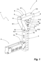
- figure 1 shows a cable support system 1, comprising a head connection part 2, a hanging support 3 and a bracket 4.
- the head connection part 2 is attached to a ceiling, not shown, by at least one screw, not shown, which passes through at least one fastening hole of the fastening holes 5, 5.1, 5.2, typically in the mounting hole 5 facing the loaded side.
- the head connection part 2 comprises a web plate 6 and side cheeks 8, 8.1 formed thereon at a bending edge 7, 7.1.
- the web plate 6 and the side walls 8, 8.1 result in a cross-sectionally U-shaped handle receptacle. Due to the U-shaped handle receptacle, the side panels 8, 8.1 laterally delimit a space into which the hanging handle 3 is inserted; the hanging support 3 is secured between the side walls 8, 8.1 on the head connection part 2 by four retaining lugs 9, 9.1 designed as latches (wherein in figure 1 only two are visible).
- the retaining tabs 9, 9.1 engage in retaining recesses 10, which are introduced into the hanging handle 3 as a row of retaining recesses.
- the retaining tabs 9, 9.1 are provided in the area of the free end section of the side walls 8, 8.1 and thus on the end area of the side walls 8, 8.1 pointing away from the web plate 6.
- first guide tabs 11, 11.1, 11.2 are provided, which enclose the upper part of the hanging handle 3 transversely to the level of the side walls 8, 8.1.
- second guide tabs 12, 12.1, 12.2 are provided (likewise one in figure 1 hidden). These also enclose the hanging handle 3 transversely to the side panels 8, 8.1. In this way, a two-point support designed at a distance from one another is provided in order to absorb bending moments acting on the hanging support 3 .
- the boom 4 is connected to the hanging support 3 by means of a connecting piece 13 .
- the connecting piece 13 has on the one hand a hammer head which cannot be seen in FIG.
- the connection piece 13 engages in recesses in the upper area of an end section of the boom 4 so that the latter is fastened to the hanging stick 3 .
- the boom is supported with its end face on the hanging support 3 .
- Opposite retaining tabs 9, 9.2; 9.1, 9.3 are each in one plane, since the holding recesses 10 of the hanging support 3 are also arranged opposite each other at the same height.
- the retaining tabs (shown there only on one side panel 8) 9, 9.1 are aligned with one another in the longitudinal direction of the hanging handle; they are arranged directly one above the other.
- Their spacing corresponds to the spacing of the retaining recesses 10 of the hanging support 3, so that the retaining tabs 9, 9.1 or 9.2, 9.3 of each side panel 8 or 8.1 can be inserted into directly adjacent retaining recesses 10 of the Hanging handle 3 intervene.
- An embodiment in which the retaining tabs are arranged at a distance from one another is also entirely possible, such that one or more further retaining recesses of the hanging support are arranged between the retaining recesses in which each retaining tab engages.
- the retaining tabs 9, 9.1, 9.2, 9.3 of this head connection part 2 issued by the side walls 8, 8.1 in the handle receptacle and so far that between the free end 15, 15.1, 15.2, 15.3 of each retaining tab 9, 9.1 , 9.2, 9.3 and the respective side wall 8, 8.1 there is a distance 16, 16.1, 16.2, 16.3.
- the distance 16, 16.1, 16.2, 16.3 is selected to be large enough that a mounted hanging support 3 grips the retaining lugs 9, 9.1, 9.2, 9.3 with its area or material enclosing the retaining recesses 10 (see also figure 4 ).
- first guide tabs 11, 11.1, 11.2, 11.3 and second guide tabs 12, 12.1, 12.2, 12.3 already mentioned above can also be seen.
- the first guide lugs 11, 11.1, 11.2, 11.3 are in the upper area of the head connection part 2 from the level of the side walls 8, 8.1 and, due to their L-shape pointing towards the free ends of the side walls 8, 8.1, form a hanging handle border transverse to the direction in which the side walls are bordered 8, 8.1.
- the bending edge 17, 17.1 resulting from the opening of these guide tabs 11, 11.1, 11.2, 11.3 is aligned orthogonally to the length of the hanging handle when installed.
- the guide tabs 11, 11.1, 11.2, 11.3 have insertion bevels, so that the hanging handle edging is guided to its nominal dimension transversely to the edging direction of the side panel 8, 8.1 along the insertion bevels.
- Second guide tabs 12, 12.1, 12.2, 12.3 are arranged in the lower area of the head connection part 2—in the area of the free ends of the side panels 8, 8.1. These also enclose the hanging handle 3 with their end faces transversely to the side panel 8, 8.1.
- a safety tab 19 can also be seen on the head connection part 2 shown, which is perforated only in the side panel 8 at the factory.
- a hanging handle 3 When a hanging handle 3 is mounted, it can be pressed into a recess in the hanging handle 3, in this case into a holding recess 10.
- the effective direction of the securing tab 19 is different from that of the retaining tabs 9, 9.1; it acts by means of a positive fit, when issued, against the lower area of a holding recess 10 of a mounted hanging handle 3 and thus in the opposite direction to the holding lugs 9, 9.1 pointing upwards.
- the securing tab 19 limits a displacement movement of the hanging support 3 in the direction of the web plate 6, so that the hanging support is prevented from being lifted off the retaining straps 9, 9.1, 9.2, 9.3.
- a recess 20 is provided for a safety element, not shown in detail, such as a screw, which not only achieves the same effect as with the safety strap 19 in relation to the hanging post 3, but also allows the U-shaped head connection part 2 to be bent apart. respectively the two side walls 8, 8.1 can be prevented.
- the load capacity of the head connection part 2 can be increased by the securing element.
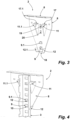
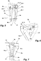
- FIGS. 5 to 7 show an alternative embodiment of a head connection part 2a.
- This head connection part 2a also has a web plate 6a and side walls 8a, 8a.1 formed thereon. Both side cheeks 8a, 8a.1 each have one holding tab 9a, 9a.1 opposite the other. Starting from the free end of the respective side wall 8a, 8a.1, these are exhibited in the direction of the web plate 6a at an angle of approximately 90° with respect to the plane of the side walls 8a, 8a.1, so that between Retaining tab 9a, 9a.1 and free end of the respective side wall 8a, 8a.1 a recess 21 is provided.
- the securing element 22 reaches through the holding recess 10 of the hanging support 3 and is also supported in the direction of the weight on the area of the side wall 8a, 8a.1 enclosing the recess 21. If a large weight acts on the hanging support 3, a possible downward deformation of the retaining lugs 9a, 9a.1 is limited as soon as they are supported on the securing element 22, which is designed as a cotter pin in the exemplary embodiment shown. Thus, the hanging stick 3 is secured to the head connector 2a at all times.
- the securing element 22 is molded onto the head connection part 2a in the delivery state of the same.
- the predetermined breaking webs 23, 23.1 can be seen in the figures. Schematically this can be done in figure 6 can be recognized: In the area of the side wall 8a.1 there is a plate-shaped fuse element blank 22' which is formed onto the head connection part 2a or onto the side wall 8a.1 by predetermined breaking webs 23', 23'.1. It can either be provided that only the material is provided as a fuse element blank 22' at the factory and the person assembling brings it into its final contour during assembly or, preferably, that the desired fuse element 22 is already provided from this material by the manufacturer.
- the head connection part 2a has first guide tabs 11a, 11a.1 in the upper region, only two of which are visible in the figures. These enclose the hanging support 3, when mounted, transversely to the side walls 8a, 8a.1.
- this head connection part 2a has two opposite mounting notches 24, 24.1.
- only one mounting notch 24 can be provided on one of the two side walls 8a, 8a.1.
- the mounting catches 24, 24.1 are only slightly issued from the respective side panel 8a, 8a.1. Nevertheless, these can engage in recesses, typically the retaining recesses 10 of a hanging stick 3 when mounted. If a hanging support 3 is mounted on the head connection part 2a, the hanging support 3 is initially temporarily held on the mounting notches 24, 24.1 until the retaining tabs 9a, 9a.1 engage in the retaining recesses 10 or the securing element 22 is positioned.
- the holding recess 10 with material limiting in the direction of the web plate 6a rests on the end face of a mounting catch 24, 24.1.
- Such an embodiment is particularly advantageous when an additional tool, not shown in detail, is used to spread apart the two side walls 8a, 8a.1 in order to simplify the assembly process. The tool then spreads the two side walls 8a, 8a.1 so far apart that the retaining tabs 9a, 9a.1 do not pose an obstacle to inserting a hanging support 3, but so little that a hanging support 3 is temporarily held by the mounting notches 24, 24.1 until the spreading tool is removed.
- the distance between retaining tabs 9a, 9a.1 and mounting notches 24, 24.1 corresponds to the spacing of the retaining recesses 10 of the hanging support 3.
- the mounting notches 24, 24.1 can also serve to absorb the load from the hanging support 3 onto the head connection part 2a.
Abstract
Die Erfindung betritt ein Kopfanschlussteil 2 zum Befestigen eines Hängestiels 3 eines Kabeltragsystems 1 an einer Decke mit einer an einer Decke befestigbaren Stegplatte 6 und zwei an gegenüberliegenden Kanten 7 der Stegplatte 6 angeformten Seitenwangen 8, 8.1 zum Ausbilden einer U-förmigen Stielaufnahme. Die zumindest eine der beiden Seitenwangen 8, 8.1 weist wenigstens eine in die Stielaufnahme ausgestellte Haltelasche 9, 9.1 auf, vorgesehen zum Eingreifen in eine Halteaussparung 10 eines Hängestiels 3, wenn dieser an dem Kopfanschlussteil 2 montiert ist.The invention relates to a head connection part 2 for fastening a hanging support 3 of a cable support system 1 to a ceiling with a web plate 6 that can be fixed to a ceiling and two side walls 8, 8.1 formed on opposite edges 7 of the web plate 6 to form a U-shaped support receptacle. The at least one of the two side panels 8, 8.1 has at least one holding tab 9, 9.1, which extends into the handle receptacle and is intended for engaging in a holding recess 10 in a hanging handle 3 when this is mounted on the head connection part 2.
Description
Die Erfindung betrifft ein Kopfanschlussteil zum Befestigen eines Hängestiels eines Kabeltragsystems an einer Decke mit einer an einer Decke befestigbaren Stegplatte und zwei an gegenüberliegenden Kanten der Stegplatte angeformten Seitenwangen zum Ausbilden einer U-förmigen Stielaufnahme.The invention relates to a head connector for attaching a hanging support of a cable support system to a ceiling, with a web plate that can be attached to a ceiling and two side walls formed on opposite edges of the web plate to form a U-shaped support receptacle.
Kabeltragsysteme dienen dem Tragen von Kabeln im Raum, beispielsweise in einem Gebäude. Hierzu verfügt das Kabeltragsystem typischerweise über eine Kabeltrasse, die etwa nach Art einer Kabelrinne, einer Kabelleiter oder einer Gitterkabelrinne ausgeführt sein kann. Auf der Kabeltrasse sind Kabel und Leitungen geführt bzw. gelegt. Eine andere Möglichkeit zum Ausbilden einer Kabeltrasse ist das Vorsehen einzelner Sprossen, über die Kabel abgestützt werden; eine durchgängige Unterstützung der Kabel wird hierdurch eingespart.Cable support systems are used to carry cables in space, for example in a building. For this purpose, the cable support system typically has a cable route, which can be designed in the manner of a cable duct, a cable ladder or a mesh cable duct. Cables and lines are routed or laid on the cable route. Another way of forming a cable route is to provide individual rungs over which cables are supported; a continuous support of the cable is thereby saved.
Zum Tragen der Kabeltrasse kann eine Deckenbefestigung vorgesehen sein. Diese erfolgt typischerweise mittels von der Decke herunterragender Hängestiele. Hängestiele zeichnen sich in aller Regel durch ein vierkantiges Hohlprofil aus, welches nicht selten als U-Profil oder Montageschiene-Profil ausgeführt ist, jedoch auch als geschlossenes Profil vorgesehen sein kann. Ein solcher Hängestiel wird mittels eines Kopfanschlussteils an der Decke befestigt.A ceiling mount can be provided to support the cable route. This is typically done by means of hanging rods protruding from the ceiling. Hanging supports are usually characterized by a square hollow profile, which is often designed as a U-profile or mounting rail profile, but can also be provided as a closed profile. Such a hanging support is attached to the ceiling by means of a head connector.
Ein Beispiel für eine Deckenbefestigung eines Hängestiels offenbart
In einer Ausgestaltung nach
Eine weitere Ausgestaltung sieht eine Kopfplatte mit einer daran angeschweißten Stielaufnahme vor.A further embodiment provides a head plate with a handle mount welded to it.
Nachteilig bei dem Stand der Technik gemäß
Vor diesem Hintergrund ist es Aufgabe der Erfindung, ein kompaktes Kopfanschlussteil vorzuschlagen, bei dem die genannten Nachteile, insbesondere die Mehrteiligkeit sowie der aufwendige Herstellungsprozess, vermieden sind und dennoch eine einfache, insbesondere werkzeuglose Montage eines Hängestiels möglich ist.Against this background, the object of the invention is to propose a compact head connection part in which the disadvantages mentioned, in particular the multiple parts and the complex manufacturing process, are avoided and a simple, in particular tool-free assembly of a hanging support is nevertheless possible.
Gelöst wird diese Aufgabe durch ein eingangs genanntes, gattungsgemäßes Kopfanschlussteil, bei dem zumindest eine der beiden Seitenwangen wenigstens eine in die Stielaufnahme ausgestellte Haltelasche aufweist, vorgesehen zum Eingreifen in eine Halteaussparung eines Hängestiels, wenn dieser an dem Kopfanschlussteil montiert ist.This object is achieved by a generic head connection part as mentioned at the outset, in which at least one of the two side walls has at least one retaining tab projected into the handle receptacle, intended to engage a retaining recess of a hanging stem when mounted to the head connector.
Vorteilhafte Ausgestaltungen ergeben sich aus den abhängigen Ansprüchen sowie der Beschreibung.Advantageous configurations emerge from the dependent claims and the description.
Durch das einstückige Vorsehen der Stielaufnahme mit der von der zumindest einen Seitenwange ausgestellten, wenigstens einen Haltelasche kann der Herstellungsprozess auf einen einfachen Stanz- und Biegeprozess eines einzigen Teils reduziert werden, der ohne aufwendige, ein Umsetzen des Werkstückes erforderliche Geometrien auskommt und gleichzeitig ein Maximum an Komfort bei der Montage bietet. Durch die U-förmige Stielaufnahme wird ein von den Seitenwangen zumindest abschnittsweise begrenzter Raum bereitgestellt, in den der Hängestiel zur Montage eingebracht wird. Auf diese Weise ist der Hängestiel beidseitig durch die Seitenwangen eingefasst und kann bevorzugt mit den Seitenwangen in Kontakt stehen. Die Seitenwangen können gegenüber der Stegplatte elastisch verstellt werden, sodass eine an die Seitenwange angeformte und in die Stielaufnahme hineinragende ausgestellte Haltelasche in eine vorgesehene Halteaussparung des Hängestiels bei der Montage eingeführt werden kann. Eine Halteaussparung kann eine Aussparung sein, die in einem wiederholten Muster entlang der Längserstreckung des Hängestiels vorgesehen ist und etwa an anderer Stelle auch an dem Hängestiel zum Befestigen einer Kabeltrasse vorgesehen ist. Auf diese Weise kann der Hängestiel an nahezu jeder beliebigen Stelle gekürzt werden, wobei eine Montage an dem Kopfanschlussteil immer möglich ist. Die Haltelasche nimmt die Gewichtskraft des Hängestiels und je nach Ausgestaltung ggf. auch ein Biegemoment auf, wenn dieser an einem erfindungsgemäßen, an einer Decke befestigten Kopfanschlussteil, montiert ist.By providing the handle receptacle in one piece with the at least one retaining tab projected by the at least one side cheek, the manufacturing process can be reduced to a simple stamping and bending process of a single part, which does not require complex geometries that require repositioning of the workpiece and at the same time provides a maximum of Provides convenience during assembly. The U-shaped handle receptacle provides a space that is delimited at least in sections by the side walls and into which the hanging handle is introduced for assembly. In this way, the hanging handle is bordered on both sides by the side panels and can preferably be in contact with the side panels. The side walls can be adjusted elastically in relation to the web plate, so that a flared holding tab, which is molded onto the side wall and protrudes into the handle receptacle, can be inserted into a holding recess provided in the hanging handle during assembly. A retaining notch may be a notch provided in a repeated pattern along the length of the hanger post and may also be provided elsewhere on the hanger post for attachment of a cable tray. In this way, the hanging support can be shortened at almost any point, with assembly on the head connection part always being possible. The retaining lug absorbs the weight of the hanging support and, depending on the design, possibly also a bending moment when this is mounted on a head connection part according to the invention that is attached to a ceiling.
Die Haltelasche ist von der Seitenwange typischerweise durch Ausstanzen ausgestellt. Hierbei wird eine Lasche an einer Biegekante mit einem Presswerkzeug aus der Ebene der Seitenwange im Rahmen eines Stanz-Umformprozesses herausgedrückt und verbleibt so entlang der Biegekante an der Seitenwange angeformt; zumindest abschnittsweise ragt die Lasche in die Stielaufnahme hinein, typischerweise mit ihrem freien Abschluss zur Stegplatte weisend. Der freie Abschluss ist das Ende der Lasche, die der Biegekante gegenüberliegt.The retaining tab is typically issued from the side panel by being punched out. In this case, a tab on a bending edge is pressed out of the plane of the side wall with a pressing tool as part of a stamping and forming process and thus remains formed along the bending edge on the side wall; At least in sections, the tab protrudes into the handle receptacle, typically with its free end facing Web plate pointing. The free end is the end of the tab opposite the bending edge.
Zum Befestigen des Kopfanschlussteils kann die Stegplatte zumindest eine Aussparung aufweisen, durch die ein Schraubbolzen hindurchführbar ist. Durch die im Querschnitt U-förmige Ausgestaltung ist von Seiten der Stielaufnahme genügend Raum, um etwaige Befestiger durch die Aussparung hindurchzuführen, durch eine Drehbewegung, auch unter Nutzung von hebelförmigen Werkzeugen wie einem Schraubschlüssel in einer Decke zu befestigen und so das Kopfanschlussteil zu fixieren. Typischerweise sind mehrere derartige Aussparungen in der Stegplatte vorgesehen, damit diese mit mehreren Befestigern deckenseitig angeschlossen werden kann.In order to fasten the head connection part, the web plate can have at least one recess through which a screw bolt can be passed. Due to the cross-sectionally U-shaped design, there is enough space on the side of the handle receptacle to guide any fasteners through the recess, to fasten them in a ceiling by means of a rotary movement, also using lever-shaped tools such as a wrench, and thus to fix the head connection part. Typically, several such recesses are provided in the web plate so that it can be connected to the ceiling with several fasteners.
Es kann vorgesehen sein, dass das Kopfanschlussteil fachwerkartig von der Decke herabragt. Dann ist das Kopfanschlussteil, insbesondere die Seitenwangen, trapezförmig. Auf diese Weise kann auch nur eine gegenüber der Hängestiellängserstreckung exzentrischer, einseitiger Anschluss des Kopfanschlussteils an der Decke erfolgen und zwar an der der Belastung zugewandten Seite der Stegplatte. Dann wirkt auf den Schraubbolzen lediglich eine Zugbelastung, während auf der der Last abgewandten Seite das Kopfanschlussteil durch die Belastung gegen die Decke gedrückt wird. Dies vereinfacht die Montage.Provision can be made for the head connection part to protrude from the ceiling in the manner of a truss. Then the head connection part, in particular the side panels, is trapezoidal. In this way, only one-sided connection of the head connection part to the ceiling, which is eccentric relative to the longitudinal extent of the hanging support, can also take place, namely on the side of the web plate facing the load. Only a tensile load then acts on the screw bolt, while on the side facing away from the load the head connection part is pressed against the ceiling by the load. This simplifies assembly.
So kann insgesamt zum Herstellen eines Kopfanschlussteils vorgesehen sein, dass in einem ersten Prozessschritt aus einer Blechplatine die erforderlichen Haltelaschen sowie etwaige weitere benötigte Aussparungen sowie andere ggf. gewünschte Elemente ausgestellt/ausgestanzt werden und dass anschließend die so vorgefertigte Platine in besagte U-Form entlang der Biegekanten der dann vorgesehenen Stegplatte gebogen wird, um eine Stielaufnahme bereitzustellen.Overall, for the production of a head connection part, it can be provided that in a first process step, the necessary retaining tabs and any other required recesses as well as other elements that may be desired are issued/punched out of a sheet metal blank and that the blank thus prefabricated is then shaped into said U-shape along the Bending edges of the then provided web plate is bent to provide a handle recording.
In einer Ausgestaltung kann vorgesehen sein, dass die zumindest eine Seitenwange wenigstens zwei Haltelaschen aufweist. Diese sind in Hängestiellängserstreckungsrichtung und somit typischerweise in Einführrichtung des Hängestiels beabstandet voneinander angeordnet. Ihr Abstand entspricht dem Abstand zweier Halteaussparungen des Hängestiels, sodass, wenn ein Hängestiel montiert ist, beide Haltelaschen in den Hängestiel formschlüssig eingreifen. Möglich ist auch, dass die beiden Haltelaschen quer zur Hängestiellängserstreckung versetzt angeordnet sind. Dies ist typischerweise dann der Fall, wenn der Hängestiel mehrere, nebeneinander angeordnete Halteaussparungen aufweist, die typischerweise in Reihen angeordnet sind. Durch das zusätzliche Vorsehen wenigstens einer weiteren, den Hängestiel abstützenden Haltelasche wird die eingeleitete Gewichtskraft auf eine größere Fläche aufgeteilt, sodass die Flächenpressung auf jede einzelne Haltelasche herabgesetzt und einer plastischen Verformung des Hängestiels und/oder der Haltelaschen entgegengewirkt wird. Zudem kann durch die Zweipunktaufnahme ein auf den Hängestiel wirkendes Biegemoment in das Kopfanschlussteil aufgefangen werden.In one embodiment, it can be provided that the at least one side panel has at least two retaining tabs. These are spaced apart from one another in the longitudinal direction of the hanging handle and thus typically in the direction of insertion of the hanging handle. Your distance corresponds to the distance between two holding recesses of the hanging support, so that if a hanging support is mounted, both retaining straps engage in the hanging support in a form-fitting manner. It is also possible for the two holding tabs to be offset transversely to the length of the hanging handle. This is typically the case when the hanging stick has a plurality of holding recesses arranged next to one another, which are typically arranged in rows. The additional provision of at least one further retaining strap supporting the hanging handle distributes the applied weight over a larger area, so that the surface pressure on each individual retaining strap is reduced and plastic deformation of the hanging handle and/or the retaining straps is counteracted. In addition, due to the two-point attachment, a bending moment acting on the hanging support can be absorbed in the head connection part.
Sind zwei Haltelaschen übereinander angeordnet, ist bevorzugt vorgesehen, dass die Haltelasche, die näher an der Stegplatte angeordnet ist, weniger weit in die Stielaufnahme hinein ausgestellt ist als die von der Stegplatte weiter entferntere. Die beiden Haltelaschen ragen dann unterschiedlich weit in die Stielaufnahme hinein bzw. von der zumindest einen Seitenwange ab. Zum Montieren des Hängestiels an dem Kopfanschlussteil werden die an der Stegplatte angeformten Seitenwangen an ihrem jeweiligen freien Ende etwas auseinandergebogen. Hier wird die Elastizität der Schenkel bzw. des Übergangs zwischen Stegplatte und Seitenwange ausgenutzt. Durch das Auseinanderbiegen stellt sich eine im Wesentlichen trapezförmige Aufnahme ein. Durch die vorstehend beschriebene Ausgestaltung liegen in diesem aufgebogenen Zustand die freien Abschlüsse der Haltelaschen etwa in einer senkrechten, an die äußere Mantelfläche des Hängestiels angepassten Ebene. Auf diese Weise ist die Kraft, die auf die Haltelaschen wirkt, auf dieselben gleichmäßig verteilt, sodass vermieden wird, dass sich diese plastisch verformen. Auch einem plastischen Verformen der Schenkel wird so entgegengewirkt. Zuletzt muss durch diese Ausgestaltung weniger Kraft zum Montieren des Hängestiels aufgewendet werden.If two retaining lugs are arranged one above the other, it is preferably provided that the retaining lug that is arranged closer to the web plate is positioned less far into the handle receptacle than the one that is further away from the web plate. The two holding tabs then protrude to different extents into the handle receptacle or from the at least one side cheek. To mount the hanging support on the head connection part, the side walls formed on the web plate are slightly bent apart at their respective free end. The elasticity of the legs or the transition between the web plate and the side wall is used here. By bending apart, an essentially trapezoidal recording is obtained. As a result of the design described above, in this bent-up state the free ends of the holding tabs lie approximately in a vertical plane adapted to the outer lateral surface of the hanging support. In this way, the force that acts on the retaining tabs is evenly distributed over them, so that plastic deformation of the latter is avoided. This also counteracts plastic deformation of the legs. Finally, due to this design, less force has to be used to mount the hanging support.
Der Winkel zwischen Seitenwange und Haltelasche beträgt typischerweise einige Grad bis 90°, sodass der freie Abschluss der Haltelasche bevorzugt nicht von der Stegplatte wegweist.The angle between the side wall and the retaining tab is typically a few degrees up to 90°, so that the free end of the retaining tab preferably does not point away from the web plate.
Es kann vorgesehen sein, dass die zumindest eine Haltelasche als Rastklinke ausgebildet ist, deren freier Abschluss in Richtung der Stegplatte weist. Der Winkel zwischen Seitenwange und Haltelasche beträgt dann einige Grad bis kleiner 90°, bevorzugt bis kleiner etwa 45°. Auf diese Weise wird durch die Haltelasche ein Widerhaken bereitgestellt: Die nach unten weisende Schräge der angestellten Haltelasche erleichtert als Stellschräge das Einführen eines Hängestiels, da durch die schräge Ebene die Seitenwangen durch eine Einführbewegung selbsttätig quer zur Einführbewegung gespreizt werden. Der Hängestiel wird dann hinreichend weit in die Stielaufnahme eingeschoben. Ein Demontieren des Hängestiels ist durch eine in die entgegengesetzte Richtung gerichtete Bewegung (etwa durch das Aufbringen einer Gewichtskraft) nicht möglich. Auf diese Weise ist der Hängestiel, wenn montiert, sicher gehalten.It can be provided that the at least one retaining tab is designed as a latch, the free end of which points in the direction of the web plate. The angle between the side wall and the retaining tab is then a few degrees to less than 90°, preferably less than about 45°. In this way, a barb is provided by the retaining tab: The downward-pointing bevel of the employed retaining tab facilitates the insertion of a hanging handle as an adjusting bevel, since the side walls are automatically spread transversely to the insertion movement through the inclined plane by an insertion movement. The hanging handle is then pushed far enough into the handle receptacle. It is not possible to dismantle the hanging support by moving in the opposite direction (e.g. by applying weight). In this way, the hanging stick is held securely when mounted.
Die Rastklinke kann so ausgebildet sein, dass das die Halteaussparung des Hängestiels umgebende Material auf dem freien Abschluss der Haltelasche, typischerweise der Stirnfläche der Haltelasche aufsteht. Dann beträgt der Winkel zwischen Haltelasche und Seitenwange nur wenige Grad, sodass der freie Abschluss der Haltelasche nicht oder nicht wesentlich von der Seitenwange beabstandet ist. Wichtig ist, dass die Schräge bzw. die Stirnfläche von der Stegplatte nur in einem solchen Winkel wegweist, dass zwischen Stirnfläche und Hängestiel eine Selbsthemmung eintritt.The latching pawl can be designed in such a way that the material surrounding the retaining cutout of the hanging rod rests on the free end of the retaining lug, typically the end face of the retaining lug. The angle between the retaining tab and the side panel is then only a few degrees, so that the free end of the retaining tab is not, or not significantly, spaced from the side panel. It is important that the bevel or the end face of the web plate only points away at such an angle that self-locking occurs between the end face and the hanging support.
Bevorzugt ist jedoch vorgesehen, dass die Haltelasche so weit in die Stielaufnahme hinein ausgestellt ist, dass zwischen Seitenwange und freiem Abschluss der Haltelasche ein solcher Abstand ist, dass der Hängestiel, wenn montiert, die Haltelasche zumindest abschnittsweise mit zumindest einem Teil des die Halteaussparung einfassenden Materials hintergreift. Der die Halteaussparung umgebende Bereich des Hängestiels ist dann zwischen Haltelasche und Seitenwange eingefasst. Hierdurch wird ein Formschluss zwischen Kopfanschlussteil und Hängestiel bereitgestellt. Wirkt eine Gewichtskraft auf den Hängestiel, wird der die Halteaussparung umgebende Bereich - genauer gesagt: Das die Halteaussparung umgebende, zur Stegplatte hin weisende Material - in die durch Haltelasche und Seitenwange gebildete Kerbe, somit zur Biegekante der Haltelasche, gezogen.However, it is preferably provided that the retaining tab is projected so far into the handle receptacle that there is such a distance between the side cheek and the free end of the retaining tab that the hanging handle, when mounted, at least partially touches at least part of the material enclosing the retaining tab behind. The area of the hanging support surrounding the holding recess is then bordered between the holding lug and the side panel. This provides a form fit between the head connection part and the hanging support. If a weight acts on the hanging support, the area surrounding the retaining recess - more precisely: the material surrounding the retaining recess and pointing towards the web plate - is pulled into the notch formed by the retaining tab and side wall, and thus to the bending edge of the retaining tab.
Zur Demontage des Hängestiels ist bei dieser Ausgestaltung ein Versetzen des Hängestiels in Richtung zur Stegplatte erforderlich, bis die Haltelasche nicht mehr in die Halteaussparung des Hängestiels hintergreift und der Hängestiel unter Spreizung der beiden Seitenwangen aus der Hängestielaufnahme entnommen werden kann.To disassemble the hanging handle in this embodiment, it is necessary to move the hanging handle in the direction of the web plate until the retaining tab no longer engages in the holding recess of the hanging handle and the hanging handle can be removed from the hanging handle receptacle by spreading the two side walls.
Um nach der Montage einer versehentlichen Demontage entgegenzuwirken, kann vorgesehen sein, dass das Kopfanschlussteil eine Sicherungslasche aufweist. Die Sicherungslasche greift in eine Aussparung, typischerweise in eine weitere Halteaussparung des Hängestiels ein. Sie soll verhindern, dass der Hängestiel in Richtung Stegplatte verschoben werden kann. Hierfür ist ihre Wirkrichtung eine andere als diejenige der zumindest einen Haltelasche. Beispielsweise kann die Winkelausrichtung zwischen Seitenwange und Lasche unterschiedlich, bevorzugt entgegengesetzt, ausgerichtet sein oder die Sicherungslasche ragt weiter in die Stielaufnahme hinein als die Haltelasche. Durch eine entsprechende Stanzperforation ist die Ausstellrichtung der Sicherungslasche bereits im Auslieferungszustand werksseitig vorgegeben, auch wenn zur Montage die Sicherungslasche noch nicht ausgestellt ist.In order to counteract inadvertent disassembly after assembly, provision can be made for the head connection part to have a securing tab. The securing tab engages in a recess, typically in a further retaining recess of the hanging handle. It should prevent the hanging support from being pushed in the direction of the web plate. For this purpose, their direction of action is different from that of the at least one retaining tab. For example, the angular alignment between the side wall and the tab can be different, preferably opposite, or the securing tab projects further into the handle receptacle than the retaining tab. The opening direction of the safety latch is already set in the delivery state by means of a corresponding punched perforation, even if the safety latch is not yet opened for assembly.
Durch das Vorsehen einer Sicherungslasche wird zudem der Montagevorgang vereinfacht: Das zusätzliche Vorsehen eines Splintes und/oder einer Schraube kann grundsätzlich entfallen; dies schließt jedoch nicht aus, dass ein solcher/eine solche montiert werden kann.The provision of a securing tab also simplifies the assembly process: the additional provision of a cotter pin and/or a screw can in principle be omitted; however, this does not rule out the possibility of installing one.
So kann auch vorgesehen sein, dass durch eine Aussparung, die unmittelbar auf der von der Stegplatte wegweisenden Seite der Haltelasche (mithin, wenn das Kopfanschlussteil an einer Decke montiert ist, unter der Haltelasche) angeordnet ist, ein Bolzen, ein Splint oder ein anderes Sicherungsteil bei montiertem Hängestiel so führbar ist, dass die zumindest eine Haltelasche an dem Sicherungsteil abgestützt ist, typischerweise durch unmittelbaren Kontakt miteinander. Das Sicherungsteil stützt sich wiederum an dem die Aussparung umgebenden Bereich der Seitenwange ab. Auf diese Weise ist verhindert, dass die Haltelasche aufgrund der auf sie wirkenden Gewichtskraft aufgebogen wird, sodass unter Umständen ihre Haltefunktion nicht mehr gewährleistet wäre.Provision can also be made for a bolt, a cotter pin or another securing part to be arranged through a recess which is directly on the side of the retaining lug pointing away from the web plate (thus, if the head connection part is mounted on a ceiling, under the retaining lug). when the hanging handle is mounted, it can be guided in such a way that the at least one retaining tab is supported on the securing part, typically by direct contact with one another. The securing part is in turn supported on the area of the side wall surrounding the recess. In this way it is prevented that the holding tab due to the acting on it Weight force is bent, so that their holding function might no longer be guaranteed.
Typischerweise wird als Aussparung in der Seitenwange die durch das Ausstellen der Haltelasche gebildete Aussparung genutzt. Die Haltelasche kann in dieser Anordnung etwa im 90°-Winkel gegenüber der Seitenwange ausgestellt sein, wobei das Ausstellen vorzugsweise von unten erfolgt. In die so durch das Ausstellen bereitgestellte Aussparung ist dann ein Bolzen einführbar.Typically, the recess formed by opening the retaining tab is used as the recess in the side panel. In this arrangement, the retaining tab can be set out at an angle of approximately 90° with respect to the side panel, with the set-out preferably taking place from below. A bolt can then be inserted into the recess provided by the opening.
Durch ein optionales Anliegen des Sicherungsteils an der jeweiligen Außenseite der beiden gegenüberliegenden Seitenwangen kann zudem verhindert werden, dass die U-förmige Anordnung der Seitenwangen unbeabsichtigt aufgebogen wird, sodass die Gefahr minimiert wird, dass die zumindest eine Haltelasche aus den Halteaussparungen des Hängestiels entfernt wird.By optionally resting the securing part on the respective outer side of the two opposite side panels, it is also possible to prevent the U-shaped arrangement of the side panels from being unintentionally bent open, so that the risk of the at least one retaining tab being removed from the retaining recesses of the hanging support is minimized.
Für einen einfachen Herstellprozess und eine einfache Montage kann vorgesehen sein, dass ein entsprechendes Sicherungsteil in Form eines Splintes im Auslieferungszustand des Kopfanschlussteils mit zumindest einem Sollbruchsteg an dasselbe angeformt ist. Alternativ kann auch vorgesehen sein, dass der Splint im Rahmen eines Knock-Out-Verfahrens bereitgestellt wird: Bei diesem Verfahren wird ein Teil des Materials herausgestanzt, gleichzeitig jedoch wieder in die Seitenwange eingequetscht, so dass es in derselben gehalten ist. Typischerweise wird hierfür Material der Seitenwange genutzt, welche für eine gewichtsreduzierende Aussparung ohnehin ausgespart wird. Eine etwaige Vorformung des Sicherungsteils, etwa eine U-förmige Querschnittsform, kann ab Werk oder im Rahmen der Montage vorgesehen sein.For a simple production process and simple assembly, it can be provided that a corresponding securing part in the form of a cotter pin is molded onto the head connection part with at least one predetermined breaking web when it is delivered. Alternatively, it can also be provided that the cotter pin is provided as part of a knock-out method: In this method, part of the material is punched out, but at the same time it is squeezed back into the side wall so that it is held in the same. Typically, material from the sidewalls is used for this, which is left out anyway for a weight-reducing recess. Any preforming of the securing part, such as a U-shaped cross-section, can be provided at the factory or as part of the assembly.
Zumindest eine Seitenwange, bevorzugt beide Seitenwangen, und die Stegplatte schließen bevorzugt einen Winkel von kleiner 90° ein. Damit ist die lichte Weite der Stielaufnahme im Bereich der Stegplatte größer als im Bereich der Enden der Seitenwangen. Auf diese Weise wirkt die zumindest eine Seitenwange auf den Hängestiel, wenn dieser montiert ist, mit einer gewissen Vorspannung und ist im Zustand, wenn ein Hängestiel montiert ist, typischerweise senkrecht gegenüber der Stegplatte ausgerichtet. Auf diese Weise ist eine besonders sichere Anbindung des Hängestiels an dem Kopfanschlussteil erreicht, gleichzeitig jedoch auch eine optimale Ausrichtung der Bauteile in Bezug auf einen Kraftfluss verwirklicht. Durch die trapezförmige Ausbildung des Querschnitts des Kopfanschlussteils können zudem in gewissen Grenzen auch unterschiedlich breite Hängestiele in dem gleichen Kopfanschlussteil fixiert werden, wobei die Seitenwangen auf einen weniger breiten Hängestiel mit einer kleineren Vorspannung als auf einen breiteren Hängestiel wirken.At least one side wall, preferably both side walls, and the web plate preferably enclose an angle of less than 90°. This means that the clear width of the handle mount in the area of the web plate is greater than in the area of the ends of the side walls. In this way, the at least one side wall acts on the hanging support when it is mounted with a certain pretension and is in the state when a hanging support is mounted is typically oriented perpendicular to the web plate. In this way, a particularly secure connection of the hanging support to the head connection part is achieved, but at the same time an optimal alignment of the components with regard to a power flow is also achieved. Due to the trapezoidal design of the cross section of the head connection part, also different widths of hanging supports can be fixed in the same head connection part within certain limits, with the side walls acting on a less wide hanging support with less pretension than on a wider hanging support.
Alternativ kann vorgesehen sein, dass zumindest eine Seitenwange, bevorzugt beide Seitenwangen und die Stegplatte einen Winkel von > 90° einschließen. Hierdurch wird das Einführen des Hängestiels zwischen die Seitenwangen vereinfacht. Durch entsprechende Sicherungselemente können die beiden Seitenwangen nach der Montage des Hängestiels an den Hängestiel herangezogen werden.Alternatively, it can be provided that at least one side wall, preferably both side walls and the web plate enclose an angle of >90°. This simplifies the insertion of the hanging support between the side walls. With appropriate securing elements, the two side walls can be pulled up after the hanging support has been mounted on the hanging support.
Bevorzugt ist vorgesehen, dass beide Seitenwangen zumindest eine Haltelasche aufweisen. Auf diese Weise ist eine symmetrische Krafteinleitung in beide Seitenwangen des Kopfanschlussteils gewährleistet. Jegliche obigen Ausführungen betreffend die Haltelasche sind besonders bevorzugt für beide Seitenwangen verwirklicht, auch wenn eine teilweise einseitige Ausführung möglich ist.Provision is preferably made for both side panels to have at least one retaining tab. In this way, a symmetrical introduction of force into both side walls of the head connection part is ensured. Any of the above statements relating to the holding tab are particularly preferably implemented for both side panels, even if a partially one-sided embodiment is possible.
Hervorzuheben ist eine Ausgestaltung, bei der die zumindest eine Haltelasche auf jeder Seite nach Art einer Rastklinke ausgebildet ist, deren freier Abschluss einen solchen Abstand zu der jeweiligen Seitenwange aufweist, dass der Hängestiel, wenn montiert, beide Haltelaschen zumindest abschnittsweise mit zumindest einem Teil des die Halteaussparung einfassenden Materials hintergreift. Sind beide Seitenwangen mit zumindest einer solchen Haltelasche ausgestattet, wird der U-förmige Querschnitt des Kopfanschlussteils durch den Hängestiel geschlossen. Ein Spreizen der Seitenwangen ist bei montiertem Hängestiel dann nicht mehr möglich; das System ist selbstsichernd. Daher kann ein solches Kopfanschlussteil ohne zusätzliche in Querrichtung wirkende Sicherungsteile auskommen.A configuration should be emphasized in which the at least one retaining lug on each side is designed in the manner of a latch, the free end of which is at such a distance from the respective side wall that the hanging handle, when mounted, at least partially contacts both retaining lugs with at least part of the die Retaining recess enclosing material engages behind. If both side panels are equipped with at least one such retaining strap, the U-shaped cross section of the head connection part is closed by the hanging handle. Spreading of the side panels is then no longer possible when the hanging support is mounted; the system is self-locking. Such a head connection part can therefore do without additional securing parts acting in the transverse direction.
Bevorzugt sind zusätzliche Führungslaschen am Kopfanschlussteil vorgesehen, die eine Querbewegung eines montierten Hängestiels begrenzen. Diese Führungslaschen ragen in die Stielaufnahme hinein und können als Wölbung oder auch geschält aus der Seitenwange hervorstehen. Die Führungslaschen fassen einen montierten Hängestiel quer zur Seitenwangenerstreckung kontaktierend ein und nehmen so ein auf den Hängestiel wirkendes Biegemoment auf. Vorzugsweise sind Führungslaschenpaare vorgesehen, zwischen denen der Hängestiel, wenn an dem Kopfanschlussteil montiert, angeordnet ist.Additional guide lugs are preferably provided on the head connection part, which limit a transverse movement of a mounted hanging support. These guide tabs protrude into the handle receptacle and can protrude from the side wall as a bulge or peeled off. The guide shackles enclose a mounted hanging support transversely to the extension of the side cheeks in contact and thus absorb a bending moment acting on the hanging support. Preferably pairs of guide lugs are provided between which the hanging stem is located when mounted on the head connector.
Hierbei kann der Abstand der Führungslaschen zueinander so vorgesehen sein, dass ein Hängestiel montierbar ist, der in Abstandsrichtung der Seitenwangen schmaler ist, als parallel zu den Seitenwangen. Auf diese Weise können unter Einsparung von Material und Ressourcen größere Kräfte übertragen werden.In this case, the spacing of the guide lugs from one another can be provided in such a way that a hanging support can be mounted which is narrower in the spacing direction of the side panels than parallel to the side panels. In this way, greater forces can be transmitted while saving material and resources.
Für eine besonders effektive Biegemomentaufnahme umfasst zumindest eine Seitenwange zwei erste Führungslaschen in einem ersten Bereich der Stielaufnahme und zwei zweite Führungslaschen in einem zweiten, von dem ersten Bereich beabstandeten Bereich der Stielaufnahme. Der zweite Bereich ist typischerweise im Bereich der freien Enden der Seitenwangen; der erste nah an der Stegplattenanbindung. Ein gewisser Abstand von der Stegplatte ist vorgesehen, damit sich zwischen diesen Führungslaschen der Hängestiel auch dann noch befindet, wenn er in seine Sicherungsstellung durch Zurückziehen desselben entgegen der Montagerichtung gebracht ist. Auf diese Weise werden zwei Einfassungen bereitgestellt, die in Bezug auf das Kopfanschlussteil hinreichend weit voneinander beabstandet sind. Die aus einem in den Hängestiel eingeleiteten Biegemoment resultierende, auf die Führungslaschen wirkende Kraft wird auf diese Weise minimiert und es wird einer Schwenkbewegung entgegengewirkt. Hierdurch kann eine höhere Sicherheit gegeben werden.For a particularly effective absorption of bending moments, at least one side cheek comprises two first guide tabs in a first area of the handle receptacle and two second guide tabs in a second area of the handle receptacle spaced apart from the first area. The second area is typically in the area of the free ends of the side walls; the first close to the web plate connection. A certain distance from the web plate is provided so that the hanging support is still located between these guide lugs when it is brought into its secured position by pulling it back against the direction of assembly. In this way two skirts are provided which are spaced sufficiently far apart with respect to the head fitting. The force acting on the guide lugs resulting from a bending moment introduced into the hanging support is minimized in this way and a pivoting movement is counteracted. This can provide greater security.
In einer Weiterbildung ist vorgesehen, dass zumindest eine Führungslasche aus der zumindest einen Seitenwange ausgestellt und damit an die Seitenwange angeformt ist. Alternativ kann auch vorgesehen sein, dass zumindest eine Führungslasche aus der Stegplatte des Kopfanschlussteils ausgestellt ist. Die durch das Ausstellen gebildete Biegekante der Führungslaschen gegenüber der Seitenwange und die Hängestiellängserstreckung, wenn ein Hängestiel montiert ist, schließen bevorzugt einen Winkel von 30° oder mehr ein. Besonders bevorzugt ist ein Winkel von etwa 45°. Idealerweise beträgt der Winkel etwa 90°. Auf diese Weise wirkt in Folge eines auf den Hängestiel wirkenden Biegemomentes auf die Führungslasche eine Kraft, die auch eine Komponente in Richtung der Längserstreckung der Biegekante der Führungslasche aufweist. Je größer dieser Anteil ist, desto besser kann die Kraft stabil in die Seitenwange aufgrund des höheren Widerstandsmomentes der Führungslasche über dieselben ohne eine Verformung eingeleitet werden.In a further development it is provided that at least one guide tab is set out from the at least one side panel and is thus formed onto the side panel. Alternatively, it can also be provided that at least one guide lug is made from the web plate of the head connection part is issued. The bending edge of the guide tabs relative to the side panel formed by the opening and the length of the hanging handle when a hanging handle is mounted preferably enclose an angle of 30° or more. An angle of about 45° is particularly preferred. Ideally, the angle is about 90°. In this way, as a result of a bending moment acting on the hanging support, a force acts on the guide strap, which also has a component in the direction of the longitudinal extension of the bending edge of the guide strap. The larger this proportion, the better the force can be stably introduced into the side wall due to the higher moment of resistance of the guide plate via the same without deformation.
Vorteilhaft ist es zudem, wenn beide Seitenwangen die vorstehend beschriebenen Führungslaschen aufweisen. Auf diese Weise ist eine symmetrische Krafteinleitung möglich. Zudem können die Führungslaschen bei gleicher Führungsfläche jeweils kleiner ausgebildet sein.It is also advantageous if both side panels have the guide lugs described above. In this way, a symmetrical introduction of force is possible. In addition, the guide tabs can each be made smaller with the same guide surface.
Durch die Einteiligkeit des beschriebenen Kopfanschlussteils ohne die Notwendigkeit, einen Fügeprozess, etwa einen Schweißprozess vorzusehen, kann nicht nur Edelstahl oder tauchfeuerverzinktes Material genutzt werden, sondern auf Grund des Verzichtes auf ein Schweißverfahren auch bandverzinktes Material. Dies wirkt sich positiv auf die Herstellkosten aus. Bandverzinktes Material ist einem Schweißprozess nicht ohne nachträgliche Korrosionsschutzbehandlung zugänglich, da beim Schweißen die schützende Zinkschicht im Bereich der Schweißnaht verdampft.Due to the one-piece design of the head connection part described without the need to provide a joining process, such as a welding process, not only stainless steel or hot-dip galvanized material can be used, but also strip-galvanized material due to the absence of a welding process. This has a positive effect on the manufacturing costs. Strip-galvanized material cannot be subjected to a welding process without subsequent anti-corrosion treatment, since the protective zinc layer in the area of the weld seam evaporates during welding.
Die Erfindung wird nachstehend anhand von Ausführungsbeispielen unter Bezugnahme auf die Figuren beschrieben. Es zeigen:
- Fig. 1:
- Montierte Teile eines Kabeltragsystems,
- Fig. 2:
- das in
Figur 1 - Fig. 2a:
- einen vergrößerten Ausschnitt des unteren Bereichs des in
Figur 2 - Fig. 3:
- das in
Figur 1 - Fig. 4:
- das in
Figur 1Figur 1 - Fig. 5:
- eine weitere Ausführungsform eines Kopfanschlussteils in einer ersten perspektivischen Ansicht,
- Fig. 6:
- das in
Figur 5 - Fig. 7:
- das in
Figur 5
- Figure 1:
- Assembled parts of a cable support system,
- Figure 2:
- this in
figure 1 shown head connection part in an isolated, perspective cross-sectional view, - Figure 2a:
- an enlarged detail of the lower part of the in
figure 2 shown head connection part, - Figure 3:
- this in
figure 1 shown head connection part in another perspective, isolated, sectional view, - Figure 4:
- this in
figure 1 shown head connection part in a sectional view with the infigure 1 shown hanging handle mounted on it, - Figure 5:
- a further embodiment of a head connection part in a first perspective view,
- Figure 6:
- this in
figure 5 shown head connection part in another perspective view and - Figure 7:
- this in
figure 5 Head connection part shown with a hanging support mounted on it, also in longitudinal section.
Das Kopfanschlussteil 2 umfasst eine Stegplatte 6 sowie daran an einer Biegekante 7, 7.1 angeformte Seitenwangen 8, 8.1. Die Stegplatte 6 sowie die Seitenwangen 8, 8.1 ergeben eine im Querschnitt U-förmige Stielaufnahme. Durch die U-förmige Stielaufnahme begrenzen die Seitenwangen 8, 8.1 seitlich einen Raum, in den der Hängestiel 3 eingesetzt ist; der Hängestiel 3 ist zwischen den Seitenwangen 8, 8.1 an dem Kopfanschlussteil 2 durch vier als Rastklinken ausgebildete Haltelaschen 9, 9.1 (wobei in
Im oberen Bereich der Seitenwangen 8, 8.1 sind (in
An dem Hängestiel 3 ist mittels eines Anschlussstücks 13 der Ausleger 4 angeschlossen. Das Anschlussstück 13 verfügt einerseits über einen in Figur 1 nicht erkennbaren Hammerkopf, der in eine Hammerkopfaussparung 14, wie sie entlang der Längserstreckung des Hängestiels 3 fortlaufend angeordnet sind, eingesetzt ist und den Hängestiel 3 von innen hintergreift. Das Anschlussstück 13 greift andererseits in den oberen Bereich eines Endabschnittes des Auslegers 4 in Aussparungen ein, sodass dieser an dem Hängestiel 3 befestigt ist. An dem dem Anschlussstück 13 gegenüberliegenden, unteren Bereich des Endabschnittes des Auslegers 4 stützt sich dieser mit seiner Stirnseite an dem Hängestiel 3 ab.The
In
Zu erkennen sind in dieser Figur auch die Haltelaschen 9, 9.1, 9.2, 9.3, von denen jeweils zwei an beiden Seitenwangen 8, 8.1 gegenüberliegend vorgesehen sind. Jeweils gegenüberliegende Haltelaschen 9, 9.2; 9.1, 9.3 befinden sich jeweils in einer Ebene, da die Halteaussparungen 10 des Hängestiels 3 ebenfalls jeweils gegenüberliegend jeweils auf gleicher Höhe angeordnet sind. In
Wie in der vergrößerten Ansicht der
In den
Im unteren Bereich des Kopfanschlussteils 2 - im Bereich der freien Enden der Seitenwangen 8, 8.1 - sind zweite Führungslaschen 12, 12.1, 12.2, 12.3 angeordnet. Auch diese fassen mit ihren Stirnflächen den Hängestiel 3 quer zur Seitenwange 8, 8.1 ein.
Das jeweilige freie Ende der beiden Seitenwangen 8, 8.1 ist von der Stielaufnahme wegweisend ausgestellt, sodass jeweils eine Leitnase 18, 18.1 bereitgestellt ist. Mithilfe der Leitnasen 18, 18.1, die in Richtung der Stielaufnahme zueinander verjüngt sind, wird ein Hängestiel 3 in die Stielaufnahme geführt, wodurch eine Montage erleichtert ist.The respective free end of the two
In
Zusätzlich ist eine Aussparung 20 für ein nicht näher dargestelltes Sicherungselement, etwa eine Schraube, vorgesehen, mit dem nicht nur der gleiche Effekt wie mit der Sicherungslasche 19 in Bezug auf den Hängestiel 3 erreicht wird, sondern auch ein Auseinanderbiegen des U-förmigen Kopfanschlussteils 2, respektive der beiden Seitenwangen 8, 8.1 verhindert werden kann. Zudem kann durch das Sicherungselement die Lastaufnahme des Kopfanschlussteils 2 erhöht werden.In addition, a
Die
Auch dieses Kopfanschlussteil 2a verfügt über eine Stegplatte 6a sowie daran angeformte Seitenwangen 8a, 8a.1. Beide Seitenwangen 8a, 8a.1 weisen jeweils eine, der jeweils anderen gegenüberliegende Haltelasche 9a, 9a.1 auf. Diese sind ausgehend von dem freien Ende der jeweiligen Seitenwange 8a, 8a.1 in Richtung Stegplatte 6a im von etwa 90°-Winkel gegenüber der Ebene der Seitenwangen 8a, 8a.1 ausgestellt, sodass zwischen Haltelasche 9a, 9a.1 und freiem Ende der jeweiligen Seitenwange 8a, 8a.1 eine Aussparung 21 vorgesehen ist.This
Durch diese Aussparung 21 ist ein Sicherungselement 22, hier in Form eines Splintes, hindurchgeführt. Bei montiertem Hängestiel 3 durchgreift das Sicherungselement 22 die Halteaussparung 10 des Hängestiels 3, und stützt sich zudem in Richtung der Gewichtskraft an dem die Aussparung 21 einfassenden Bereich der Seitenwange 8a, 8a.1 ab. Wirkt eine große Gewichtskraft auf den Hängestiel 3, ist eine mögliche Verformung der Haltelaschen 9a, 9a.1 nach unten hin begrenzt, sobald sie sich auf dem bei dem dargestellten Ausführungsbeispiel als Splint ausgeführten Sicherungselement 22 abstützen. So ist der Hängestiel 3 zu jeder Zeit an dem Kopfanschlussteil 2a gesichert.Through this
Das Sicherungselement 22 ist im Auslieferungszustand des Kopfanschlussteils 2a an dasselbe angeformt. In den Figuren sind die Sollbruchstege 23, 23.1 erkennbar. Schematisch kann dies in
Wie auch das vorstehend beschriebene Kopfanschlussteil 2 verfügt das Kopfanschlussteil 2a im oberen Bereich über erste Führungslaschen 11a, 11a.1, von denen in den Figuren vorliegend nur zwei sichtbar sind. Diese fassen den Hängestiel 3, wenn montiert, quer zu den Seitenwangen 8a, 8a.1 ein.Like the
Zudem verfügt dieses Kopfanschlussteil 2a über zwei gegenüberliegende Montagerasten 24, 24.1. Grundsätzlich kann auch nur eine Montageraste 24 an einer der beiden Seitenwangen 8a, 8a.1 vorgesehen sein. Die Montagerasten 24, 24.1 sind von der jeweiligen Seitenwange 8a, 8a.1 nur geringfügig ausgestellt. Dennoch können diese in Aussparungen, typischerweise die Halteaussparungen 10 eines Hängestiels 3, wenn montiert, eingreifen. Wird ein Hängestiel 3 an dem Kopfanschlussteil 2a montiert, wird der Hängestiel 3 zunächst an den Montagerasten 24, 24.1 provisorisch gehalten, bis die Haltelaschen 9a, 9a.1 in die Halteaussparungen 10 eingreifen bzw. das Sicherungselement 22 positioniert ist. Bei diesem Halten steht die Halteaussparung 10 mit in Richtung der Stegplatte 6a begrenzendem Material auf der Stirnfläche einer Montageraste 24, 24.1 auf. Eine solche Ausgestaltung ist insbesondere dann vorteilhaft, wenn zum Aufspreizen der beiden Seitenwangen 8a, 8a.1 ein zusätzliches, nicht näher dargestelltes Werkzeug genutzt wird, um den Montagevorgang zu vereinfachen. Das Werkzeug spreizt dann die beiden Seitenwangen 8a, 8a.1 so weit auseinander, dass die Haltelaschen 9a, 9a.1 kein Hindernis für ein Einführen eines Hängestiels 3 darstellen, jedoch so wenig, dass ein Hängestiel 3 durch die Montagerasten 24, 24.1 provisorisch gehalten wird, bis dass das Spreizwerkzeug entfernt wird. Aus diesem Grunde ist der Abstand zwischen Haltelaschen 9a, 9a.1 und Montagerasten 24, 24.1 entsprechend dem Abstand der Halteaussparungen 10 des Hängestiels 3. Auch können die Montagerasten 24, 24.1 der Lastaufnahme ausgehend von dem Hängestiel 3 auf das Kopfanschlussteil 2a dienen.In addition, this
Die Erfindung ist anhand von Ausführungsbeispielen beschrieben worden. Ohne den Schutzbereich, beschrieben durch die Ansprüche, zu verlassen, ergeben sich für den Fachmann zahlreiche weitere Ausgestaltungen, den Erfindungsgedanken zu verwirklichen, ohne dass diese im Rahmen dieser Ausführungen näher erläutert werden müssten.The invention has been described using exemplary embodiments. Without departing from the scope of protection described by the claims, there are numerous further configurations for the person skilled in the art to realize the idea of the invention, without these having to be explained in more detail in the context of these descriptions.
- 11
- Kabeltragsystemcable support system
- 2,2a2.2a
- Kopfanschlussteilhead connector
- 33
- Hängestielhanging stick
- 44
- Auslegerboom
- 5, 5.1, 5.25, 5.1, 5.2
- Befestigungslochmounting hole
- 6, 6a6, 6a
- Stegplatteweb plate
- 7, 7.17, 7.1
- Biegekante der Seitenwangebending edge of the side wall
- 8, 8.1, 8a, 8a.18, 8.1, 8a, 8a.1
- Seitenwangesidewall
- 9, 9.1, 9.2, 9.3, 9a, 9a.19, 9.1, 9.2, 9.3, 9a, 9a.1
- Haltelascheretaining tab
- 1010
- Halteaussparungholding recess
- 11, 11.1, 11.2, 11.3, 11a, 11a.111, 11.1, 11.2, 11.3, 11a, 11a.1
- erste Führungslaschefirst guide tab
- 12, 12.1, 12.2, 12.312, 12.1, 12.2, 12.3
- zweite Führungslaschesecond guide tab
- 1313
- Anschlussstückfitting
- 1414
- Hammerkopfaussparunghammer head recess
- 15, 15.1, 15.2, 15.315, 15.1, 15.2, 15.3
- freier Abschlussfree degree
- 16, 16.1, 16.2, 16.316, 16.1, 16.2, 16.3
- AbstandDistance
- 17, 17.117, 17.1
- Biegekante der ersten FührungslascheBending edge of the first guide strap
- 18, 18.118, 18.1
- Leitnaseleading nose
- 1919
- Sicherungslaschesecuring tab
- 2020
- Aussparung für SicherungsbolzenRecess for safety bolts
- 2121
- Aussparung für BolzenRecess for bolts
- 2222
- Sicherungselementfuse element
- 22'22'
- Sicherungselementrohlingfuse element blank
- 23, 23.1, 23', 23'.123, 23.1, 23', 23'.1
- Sollbruchstegpredetermined breaking point
- 24, 24.124, 24.1
- Montagerastemounting notch
Claims (14)
Applications Claiming Priority (1)
| Application Number | Priority Date | Filing Date | Title |
|---|---|---|---|
| DE202021104122.6U DE202021104122U1 (en) | 2021-08-03 | 2021-08-03 | Head connector for attaching a hanging support of a cable support system to a ceiling |
Publications (1)
| Publication Number | Publication Date |
|---|---|
| EP4131682A1 true EP4131682A1 (en) | 2023-02-08 |
Family
ID=82786890
Family Applications (1)
| Application Number | Title | Priority Date | Filing Date |
|---|---|---|---|
| EP22188005.7A Pending EP4131682A1 (en) | 2021-08-03 | 2022-08-01 | Head connection for attaching a suspended handle of a cable support system to a ceiling |
Country Status (2)
| Country | Link |
|---|---|
| EP (1) | EP4131682A1 (en) |
| DE (1) | DE202021104122U1 (en) |
Citations (5)
| Publication number | Priority date | Publication date | Assignee | Title |
|---|---|---|---|---|
| EP1589626A1 (en) * | 2004-04-19 | 2005-10-26 | Vergokan | Snap-fitting suspension assembly for cable trays |
| EP2808964B1 (en) | 2013-05-31 | 2015-11-04 | Legrand France | System for providing a horizontal mounting for an object such as a cable trough and rail for such a system |
| FR3048563A1 (en) * | 2016-03-03 | 2017-09-08 | Niedax France | FIXTURE FOR SUPPORTING CABLES PATHS, ASSEMBLY COMPRISING A SUPPORT PROFILE AND SUCH A FOB |
| WO2018109420A1 (en) | 2016-12-16 | 2018-06-21 | Legrand France | System comprising a carrier rail and a plate configured to be attached to a support and to immobilise the rail arranged standing under the support |
| EP3567686A1 (en) * | 2018-05-07 | 2019-11-13 | HILTI Aktiengesellschaft | Assembly structure for at least one line |
-
2021
- 2021-08-03 DE DE202021104122.6U patent/DE202021104122U1/en active Active
-
2022
- 2022-08-01 EP EP22188005.7A patent/EP4131682A1/en active Pending
Patent Citations (5)
| Publication number | Priority date | Publication date | Assignee | Title |
|---|---|---|---|---|
| EP1589626A1 (en) * | 2004-04-19 | 2005-10-26 | Vergokan | Snap-fitting suspension assembly for cable trays |
| EP2808964B1 (en) | 2013-05-31 | 2015-11-04 | Legrand France | System for providing a horizontal mounting for an object such as a cable trough and rail for such a system |
| FR3048563A1 (en) * | 2016-03-03 | 2017-09-08 | Niedax France | FIXTURE FOR SUPPORTING CABLES PATHS, ASSEMBLY COMPRISING A SUPPORT PROFILE AND SUCH A FOB |
| WO2018109420A1 (en) | 2016-12-16 | 2018-06-21 | Legrand France | System comprising a carrier rail and a plate configured to be attached to a support and to immobilise the rail arranged standing under the support |
| EP3567686A1 (en) * | 2018-05-07 | 2019-11-13 | HILTI Aktiengesellschaft | Assembly structure for at least one line |
Also Published As
| Publication number | Publication date |
|---|---|
| DE202021104122U1 (en) | 2022-11-07 |
Similar Documents
| Publication | Publication Date | Title |
|---|---|---|
| EP3721028B1 (en) | Scaffold having an anti-lift-out device and method for securing a scaffold platform against lifting out | |
| EP1987213B1 (en) | Slab formwork system | |
| WO2019048362A1 (en) | Bracket connector for mounting rails | |
| EP1135616A1 (en) | T-link between two profile bars | |
| DE202012012290U1 (en) | Fastening device for fastening plate-shaped components | |
| DE202006003836U1 (en) | Ceiling formwork system | |
| EP3746627B1 (en) | Mounting bracket for mounting top rails of venetian blinds | |
| EP0735209B1 (en) | Cross or longitudinal supporting section for a ceiling covering | |
| EP2783437B1 (en) | Mounting rail for cabinet | |
| EP0329060B1 (en) | Supporting device for a wall or ceiling covering | |
| EP1388620B1 (en) | Connection element for a mounting system | |
| EP3461963B1 (en) | Supporting construction system and system of connecting elements for the supporting construction | |
| EP4131682A1 (en) | Head connection for attaching a suspended handle of a cable support system to a ceiling | |
| EP2270403B1 (en) | Solar collector with bearing rail | |
| EP3071896A1 (en) | Holding device for a housing and method for mounting the housing using the holding device | |
| DE102021120323B4 (en) | Cantilever supported on one end for a cable support system | |
| EP1505705B1 (en) | Mounting device for cable channel | |
| EP1010837A1 (en) | Metal scaffold board | |
| DE102022125081B3 (en) | Floor support of a cable support system | |
| EP0279049A2 (en) | Shuttering board-support for concrete shutterings | |
| EP0818592A1 (en) | Reinforcing system | |
| WO2024068756A1 (en) | Support device of a cable carrying system | |
| EP3231954A1 (en) | Length-adjustable hanger for anchoring a suspended false ceiling | |
| DE2632032C3 (en) | Bracket for verge cladding | |
| EP4145651A1 (en) | Cantilever arm for a cable support system supported at the end on one side |
Legal Events
| Date | Code | Title | Description |
|---|---|---|---|
| PUAI | Public reference made under article 153(3) epc to a published international application that has entered the european phase |
Free format text: ORIGINAL CODE: 0009012 |
|
| STAA | Information on the status of an ep patent application or granted ep patent |
Free format text: STATUS: THE APPLICATION HAS BEEN PUBLISHED |
|
| AK | Designated contracting states |
Kind code of ref document: A1 Designated state(s): AL AT BE BG CH CY CZ DE DK EE ES FI FR GB GR HR HU IE IS IT LI LT LU LV MC MK MT NL NO PL PT RO RS SE SI SK SM TR |
|
| P01 | Opt-out of the competence of the unified patent court (upc) registered |
Effective date: 20230529 |
|
| STAA | Information on the status of an ep patent application or granted ep patent |
Free format text: STATUS: REQUEST FOR EXAMINATION WAS MADE |
|
| 17P | Request for examination filed |
Effective date: 20230801 |
|
| RBV | Designated contracting states (corrected) |
Designated state(s): AL AT BE BG CH CY CZ DE DK EE ES FI FR GB GR HR HU IE IS IT LI LT LU LV MC MK MT NL NO PL PT RO RS SE SI SK SM TR |