EP4131568A1 - Dispositif et procédé de gestion de batterie - Google Patents
Dispositif et procédé de gestion de batterie Download PDFInfo
- Publication number
- EP4131568A1 EP4131568A1 EP22739636.3A EP22739636A EP4131568A1 EP 4131568 A1 EP4131568 A1 EP 4131568A1 EP 22739636 A EP22739636 A EP 22739636A EP 4131568 A1 EP4131568 A1 EP 4131568A1
- Authority
- EP
- European Patent Office
- Prior art keywords
- voltage
- cycle
- battery
- deviation
- criterion
- Prior art date
- Legal status (The legal status is an assumption and is not a legal conclusion. Google has not performed a legal analysis and makes no representation as to the accuracy of the status listed.)
- Pending
Links
- 238000000034 method Methods 0.000 title description 8
- 238000007726 management method Methods 0.000 claims description 39
- 230000008859 change Effects 0.000 claims description 22
- 230000014759 maintenance of location Effects 0.000 claims description 16
- 238000010586 diagram Methods 0.000 description 12
- 239000007773 negative electrode material Substances 0.000 description 9
- 239000000463 material Substances 0.000 description 7
- 230000008901 benefit Effects 0.000 description 5
- 230000015556 catabolic process Effects 0.000 description 5
- 238000006243 chemical reaction Methods 0.000 description 5
- 238000006731 degradation reaction Methods 0.000 description 5
- 230000006870 function Effects 0.000 description 5
- OKTJSMMVPCPJKN-UHFFFAOYSA-N Carbon Chemical compound [C] OKTJSMMVPCPJKN-UHFFFAOYSA-N 0.000 description 4
- PXHVJJICTQNCMI-UHFFFAOYSA-N Nickel Chemical compound [Ni] PXHVJJICTQNCMI-UHFFFAOYSA-N 0.000 description 4
- 239000002131 composite material Substances 0.000 description 4
- 229910002804 graphite Inorganic materials 0.000 description 4
- 239000010439 graphite Substances 0.000 description 4
- 238000012986 modification Methods 0.000 description 4
- 230000004048 modification Effects 0.000 description 4
- 230000000694 effects Effects 0.000 description 3
- 230000008569 process Effects 0.000 description 3
- WHXSMMKQMYFTQS-UHFFFAOYSA-N Lithium Chemical compound [Li] WHXSMMKQMYFTQS-UHFFFAOYSA-N 0.000 description 2
- 239000011149 active material Substances 0.000 description 2
- 229910052744 lithium Inorganic materials 0.000 description 2
- 229910052759 nickel Inorganic materials 0.000 description 2
- UFHFLCQGNIYNRP-UHFFFAOYSA-N Hydrogen Chemical compound [H][H] UFHFLCQGNIYNRP-UHFFFAOYSA-N 0.000 description 1
- HBBGRARXTFLTSG-UHFFFAOYSA-N Lithium ion Chemical compound [Li+] HBBGRARXTFLTSG-UHFFFAOYSA-N 0.000 description 1
- OJIJEKBXJYRIBZ-UHFFFAOYSA-N cadmium nickel Chemical compound [Ni].[Cd] OJIJEKBXJYRIBZ-UHFFFAOYSA-N 0.000 description 1
- 238000004891 communication Methods 0.000 description 1
- 230000000052 comparative effect Effects 0.000 description 1
- 230000003247 decreasing effect Effects 0.000 description 1
- 238000007599 discharging Methods 0.000 description 1
- 238000004146 energy storage Methods 0.000 description 1
- 229910052739 hydrogen Inorganic materials 0.000 description 1
- 239000001257 hydrogen Substances 0.000 description 1
- 229910001416 lithium ion Inorganic materials 0.000 description 1
- 230000003446 memory effect Effects 0.000 description 1
- QELJHCBNGDEXLD-UHFFFAOYSA-N nickel zinc Chemical compound [Ni].[Zn] QELJHCBNGDEXLD-UHFFFAOYSA-N 0.000 description 1
- 230000001151 other effect Effects 0.000 description 1
- 238000012545 processing Methods 0.000 description 1
- 238000011160 research Methods 0.000 description 1
- 238000006467 substitution reaction Methods 0.000 description 1
- 230000001502 supplementing effect Effects 0.000 description 1
Images


Classifications
-
- H—ELECTRICITY
- H01—ELECTRIC ELEMENTS
- H01M—PROCESSES OR MEANS, e.g. BATTERIES, FOR THE DIRECT CONVERSION OF CHEMICAL ENERGY INTO ELECTRICAL ENERGY
- H01M10/00—Secondary cells; Manufacture thereof
- H01M10/42—Methods or arrangements for servicing or maintenance of secondary cells or secondary half-cells
- H01M10/44—Methods for charging or discharging
- H01M10/448—End of discharge regulating measures
-
- H—ELECTRICITY
- H02—GENERATION; CONVERSION OR DISTRIBUTION OF ELECTRIC POWER
- H02J—CIRCUIT ARRANGEMENTS OR SYSTEMS FOR SUPPLYING OR DISTRIBUTING ELECTRIC POWER; SYSTEMS FOR STORING ELECTRIC ENERGY
- H02J7/00—Circuit arrangements for charging or depolarising batteries or for supplying loads from batteries
- H02J7/007—Regulation of charging or discharging current or voltage
- H02J7/00712—Regulation of charging or discharging current or voltage the cycle being controlled or terminated in response to electric parameters
- H02J7/007182—Regulation of charging or discharging current or voltage the cycle being controlled or terminated in response to electric parameters in response to battery voltage
-
- G—PHYSICS
- G01—MEASURING; TESTING
- G01R—MEASURING ELECTRIC VARIABLES; MEASURING MAGNETIC VARIABLES
- G01R19/00—Arrangements for measuring currents or voltages or for indicating presence or sign thereof
- G01R19/165—Indicating that current or voltage is either above or below a predetermined value or within or outside a predetermined range of values
- G01R19/16533—Indicating that current or voltage is either above or below a predetermined value or within or outside a predetermined range of values characterised by the application
- G01R19/16538—Indicating that current or voltage is either above or below a predetermined value or within or outside a predetermined range of values characterised by the application in AC or DC supplies
- G01R19/16542—Indicating that current or voltage is either above or below a predetermined value or within or outside a predetermined range of values characterised by the application in AC or DC supplies for batteries
-
- H—ELECTRICITY
- H01—ELECTRIC ELEMENTS
- H01M—PROCESSES OR MEANS, e.g. BATTERIES, FOR THE DIRECT CONVERSION OF CHEMICAL ENERGY INTO ELECTRICAL ENERGY
- H01M10/00—Secondary cells; Manufacture thereof
- H01M10/42—Methods or arrangements for servicing or maintenance of secondary cells or secondary half-cells
- H01M10/44—Methods for charging or discharging
-
- H—ELECTRICITY
- H01—ELECTRIC ELEMENTS
- H01M—PROCESSES OR MEANS, e.g. BATTERIES, FOR THE DIRECT CONVERSION OF CHEMICAL ENERGY INTO ELECTRICAL ENERGY
- H01M10/00—Secondary cells; Manufacture thereof
- H01M10/42—Methods or arrangements for servicing or maintenance of secondary cells or secondary half-cells
- H01M10/48—Accumulators combined with arrangements for measuring, testing or indicating the condition of cells, e.g. the level or density of the electrolyte
-
- H—ELECTRICITY
- H02—GENERATION; CONVERSION OR DISTRIBUTION OF ELECTRIC POWER
- H02J—CIRCUIT ARRANGEMENTS OR SYSTEMS FOR SUPPLYING OR DISTRIBUTING ELECTRIC POWER; SYSTEMS FOR STORING ELECTRIC ENERGY
- H02J7/00—Circuit arrangements for charging or depolarising batteries or for supplying loads from batteries
- H02J7/0047—Circuit arrangements for charging or depolarising batteries or for supplying loads from batteries with monitoring or indicating devices or circuits
- H02J7/0048—Detection of remaining charge capacity or state of charge [SOC]
-
- H—ELECTRICITY
- H02—GENERATION; CONVERSION OR DISTRIBUTION OF ELECTRIC POWER
- H02J—CIRCUIT ARRANGEMENTS OR SYSTEMS FOR SUPPLYING OR DISTRIBUTING ELECTRIC POWER; SYSTEMS FOR STORING ELECTRIC ENERGY
- H02J7/00—Circuit arrangements for charging or depolarising batteries or for supplying loads from batteries
- H02J7/007—Regulation of charging or discharging current or voltage
- H02J7/00712—Regulation of charging or discharging current or voltage the cycle being controlled or terminated in response to electric parameters
- H02J7/007182—Regulation of charging or discharging current or voltage the cycle being controlled or terminated in response to electric parameters in response to battery voltage
- H02J7/007184—Regulation of charging or discharging current or voltage the cycle being controlled or terminated in response to electric parameters in response to battery voltage in response to battery voltage gradient
-
- G—PHYSICS
- G01—MEASURING; TESTING
- G01R—MEASURING ELECTRIC VARIABLES; MEASURING MAGNETIC VARIABLES
- G01R31/00—Arrangements for testing electric properties; Arrangements for locating electric faults; Arrangements for electrical testing characterised by what is being tested not provided for elsewhere
- G01R31/36—Arrangements for testing, measuring or monitoring the electrical condition of accumulators or electric batteries, e.g. capacity or state of charge [SoC]
- G01R31/382—Arrangements for monitoring battery or accumulator variables, e.g. SoC
- G01R31/3835—Arrangements for monitoring battery or accumulator variables, e.g. SoC involving only voltage measurements
-
- H—ELECTRICITY
- H01—ELECTRIC ELEMENTS
- H01M—PROCESSES OR MEANS, e.g. BATTERIES, FOR THE DIRECT CONVERSION OF CHEMICAL ENERGY INTO ELECTRICAL ENERGY
- H01M10/00—Secondary cells; Manufacture thereof
- H01M10/42—Methods or arrangements for servicing or maintenance of secondary cells or secondary half-cells
- H01M10/425—Structural combination with electronic components, e.g. electronic circuits integrated to the outside of the casing
- H01M2010/4271—Battery management systems including electronic circuits, e.g. control of current or voltage to keep battery in healthy state, cell balancing
-
- Y—GENERAL TAGGING OF NEW TECHNOLOGICAL DEVELOPMENTS; GENERAL TAGGING OF CROSS-SECTIONAL TECHNOLOGIES SPANNING OVER SEVERAL SECTIONS OF THE IPC; TECHNICAL SUBJECTS COVERED BY FORMER USPC CROSS-REFERENCE ART COLLECTIONS [XRACs] AND DIGESTS
- Y02—TECHNOLOGIES OR APPLICATIONS FOR MITIGATION OR ADAPTATION AGAINST CLIMATE CHANGE
- Y02E—REDUCTION OF GREENHOUSE GAS [GHG] EMISSIONS, RELATED TO ENERGY GENERATION, TRANSMISSION OR DISTRIBUTION
- Y02E60/00—Enabling technologies; Technologies with a potential or indirect contribution to GHG emissions mitigation
- Y02E60/10—Energy storage using batteries
Definitions
- the present disclosure relates to a battery management apparatus and method, and more particularly, to a battery management apparatus and method capable of improving the performance efficiency of a battery.
- Batteries commercially available at present include nickel-cadmium batteries, nickel hydrogen batteries, nickel-zinc batteries, lithium batteries and the like.
- the lithium batteries are in the limelight since they have almost no memory effect compared to nickel-based batteries and also have very low self-charging rate and high energy density.
- the present disclosure is designed to solve the problems of the related art, and therefore the present disclosure is directed to providing a battery management apparatus and method capable of increasing the performance efficiency and lifespan of a battery by adjusting a discharge termination voltage of the battery.
- a battery management apparatus may comprise: a measuring unit configured to measure a voltage of a battery after discharge of the battery is terminated to a preset discharge termination voltage in every cycle; and a control unit configured to receive voltage information of the battery from the measuring unit in every cycle, calculate a first voltage deviation of the battery based on a preset first criterion voltage and the voltage of the battery, calculate a second voltage deviation between the first voltage deviation and a preset second criterion voltage in each cycle, and adjust the discharge termination voltage based on a criterion deviation set to correspond to a current cycle and the second voltage deviation calculated in the current cycle.
- the control unit may be configured to determine a cycle region to which the current cycle belongs among a plurality of preset cycle regions, and adjust the discharge termination voltage based on a criterion deviation set for the determined cycle region and the calculated second voltage deviation.
- the control unit may be configured to increase the discharge termination voltage, when the calculated second voltage deviation is equal to or greater than the criterion deviation.
- the plurality of cycle regions may be set based on a capacity retention rate of each cycle for a reference cell corresponding to the battery.
- the control unit may be configured to obtain a capacity profile representing a corresponding relationship between a cycle and a capacity for a reference cell corresponding to the battery, and classify and set a plurality of cycles included in the capacity profile into a plurality of cycle regions according to a capacity change rate for the cycle.
- the control unit may be configured to set the criterion deviation for each of the plurality of cycle regions, so that the criterion deviation corresponding to a first cycle region among the plurality of cycle regions is lower than the criterion deviation corresponding to the remaining cycle regions.
- control unit may be configured to change the second criterion voltage to the first voltage deviation corresponding to a cycle after the discharge termination voltage is changed.
- the measuring unit may be configured to measure a rest voltage of the battery and transmit the rest voltage as the voltage information of the battery, after a predetermined time elapses from the termination of discharge of the battery.
- the control unit may be configured to calculate the first voltage deviation by computing a difference between the rest voltage and the first criterion voltage.
- a battery pack according to another aspect of the present disclosure may comprise the battery management apparatus according to an aspect of the present disclosure.
- a battery management method may comprise: a voltage measuring step of measuring a voltage of a battery after discharge of the battery is terminated to a preset discharge termination voltage in every cycle; a first voltage deviation calculating step of calculating a first voltage deviation of the battery based on a preset first criterion voltage and the voltage of the battery; a second voltage deviation calculating step of calculating a second voltage deviation between the first voltage deviation and a preset second criterion voltage in each cycle; and a discharge termination voltage adjusting step of adjusting the discharge termination voltage based on a criterion deviation set to correspond to a current cycle and the second voltage deviation calculated in the current cycle.
- the battery management apparatus has an advantage of improving the performance efficiency of the battery and increasing the lifespan of the battery by adjusting the discharge termination voltage based on the voltage of the battery.
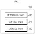
- FIG. 1 is a diagram schematically showing a battery management apparatus 100 according to an embodiment of the present disclosure.
- the battery management apparatus 100 may include a measuring unit 110 and a control unit 120.
- the measuring unit 110 may be configured to measure the voltage of the battery after the discharge of the battery is terminated to a preset discharge termination voltage in every cycle.
- the battery means one physically separable independent cell including a negative electrode terminal and a positive electrode terminal.
- one pouch-type lithium-ion battery may be regarded as a battery.
- the cycle may represent the number of times that the battery is completely discharged after being fully charged.
- a process in which the battery is charged from 0% to 100% of SOC (State of Charge) and the battery is discharged from 100% to 0% of SOC may be expressed as one cycle.
- the measuring unit 110 may be configured to measure the rest voltage of the battery after a predetermined time elapses from the termination of discharge of the battery.
- the measuring unit 110 may measure the OCV (Open Circuit Voltage) of the battery after a predetermined time elapses from the termination of discharge of the battery.
- OCV Open Circuit Voltage
- control unit 120 may be configured to receive the voltage information of the battery from the measuring unit 110 in every cycle.
- control unit 120 may be connected to communicate with the measuring unit 110. Accordingly, the control unit 120 may receive voltage information of the battery from the measuring unit 110 in every cycle.
- the measuring unit 110 may be configured to transmit the voltage information of the battery to the control unit 120 in every cycle, so that the rest voltage is transmitted as the voltage information of the battery.
- the control unit 120 may be configured to calculate a first voltage deviation of the battery based on a preset first criterion voltage and the voltage of the battery.
- control unit 120 may calculate the first voltage deviation by computing Formula 1 below.
- VD 1 V ⁇ VR 1
- VD1 may be the first voltage deviation
- V may be the voltage of the battery measured by the measuring unit 110
- VR1 may be the first criterion voltage
- the first criterion voltage is set for a battery in a BOL (Beginning of Life) state, and may be set as an open circuit voltage for the battery in a BOL state.
- the first criterion voltage may be set as an open circuit voltage after the discharge to the battery in a BOL state is terminated. That is, the first voltage deviation VD1 may be calculated according to the difference between the preset first criterion voltage (open circuit voltage) and the measured voltage (open circuit voltage) of the battery.
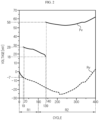
- FIG. 2 is a diagram schematically showing a voltage profile Pv of a battery according to an embodiment of the present disclosure and a voltage profile Rv of a reference cell.
- the voltage profile Pv of the battery may be a profile representing a corresponding relationship between the cycle and the voltage of the battery.
- the first voltage deviation VD1 in the 0 th cycle, may be preset to 0 mV.
- the first voltage deviation VD1 may be calculated as -7 mV. That is, in the 19 th cycle, the voltage (V) of the battery may be lower than the first criterion voltage VR1.
- the control unit 120 may be configured to calculate a second voltage deviation between the first voltage deviation and a preset second criterion voltage in each cycle.
- control unit 120 may calculate the second voltage deviation by computing Formula 2 below.
- VD 2 VD 1 ⁇ VR 2
- VD2 may be a second voltage deviation
- VD1 may be the first voltage deviation according to Formula 1
- VR2 may be the second criterion voltage.
- the second criterion voltage VR2 may be the first voltage deviation VD1 in the 0 th cycle or a cycle immediately after the discharge termination voltage is changed.
- the second criterion voltage VR2 of the 0 th to 19 th cycles may be 0 mV. That is, the criterion cycle in the 0 th to 19 th cycles may be the 0 th cycle, and the second criterion voltage VR2 may be 0 mV which is the first voltage deviation VD1 of the 0 th cycle. That is, in the 0 th cycle, the first voltage deviation VD1 and the second criterion voltage VR2 may be preset to 0 mV.
- the control unit 120 may calculate the second voltage deviation VD2 by computing the difference between the first voltage deviation VD1 and the second criterion voltage VR2 of the battery according to Formula 2.
- the second criterion voltage VR2 of the 20 th cycle to the 139 th cycle may be 28 mV. That is, the criterion cycle in the 20 th cycle to the 139 th cycle may be the 20 th cycle, and the second criterion voltage VR2 may be 28 mV which is the first voltage deviation VD1 of the 20 th cycle.
- the control unit 120 may calculate the second voltage deviation VD2 by computing the difference between the first voltage deviation VD1 and the second criterion voltage VR2 of the battery according to Formula 2.
- the criterion cycle after the 140 th cycle may be the 140 th cycle
- the second criterion voltage VR2 may be 56 mV, which is the first voltage deviation VD1 of the 140 th cycle.
- the control unit 120 may calculate the second voltage deviation VD2 by computing the difference between the first voltage deviation VD1 and the second criterion voltage VR2 of the battery according to Formula 2.
- the control unit 120 may be configured to adjust the discharge termination voltage based on a criterion deviation set to correspond to the current cycle and the second voltage deviation calculated in the current cycle.
- control unit 120 may be configured to determine a cycle region to which the current cycle belongs among a plurality of preset cycle regions.
- the plurality of cycle regions may include a first cycle region R1 and a second cycle region R2.
- the first cycle region R1 may include 0 th to 100 th cycles
- the second cycle region R2 may include 101 st to 400 th cycles.
- control unit 120 may be configured to adjust the discharge termination voltage based on the criterion deviation set for the determined cycle region and the calculated second voltage deviation.
- control unit 120 may be configured to increase the discharge termination voltage, when the calculated second voltage deviation is greater than or equal to the criterion deviation. Conversely, if the calculated second voltage deviation is less than the criterion deviation, the control unit 120 may maintain the discharge termination voltage as it is.
- the criterion deviation set for the first cycle region R1 may be 7 mV
- the criterion deviation set for the second cycle region R2 may be 10 mV
- the second voltage deviation calculated in the 19 th cycle may be 7 mV. That is, in the 19 th cycle, since the second voltage deviation (7 mv) between the second criterion voltage (0 mV) and the first voltage deviation (-7 mV) is greater than or equal to the criterion deviation (7 mV) set for the first cycle region R1, the control unit 120 may increase the discharge termination voltage from the 20 th cycle.
- the second criterion voltage may be changed from 0 mV to 28 mV from the 20 th cycle. That is, after the discharge termination voltage is changed, the control unit 120 may be configured to change the second criterion voltage to the first voltage deviation corresponding to a cycle after the discharge termination voltage is changed.
- the second voltage deviation calculated in the 139 th cycle may be 10 mV. That is, in the 139 th cycle, since the second voltage deviation (10 mV) between the second criterion voltage (28 mV) and the first voltage deviation (18 mV) is greater than or equal to the criterion deviation (10 mV) set for the second cycle region R2, the control unit 120 may further increase the discharge termination voltage from the 140 th cycle.
- the second criterion voltage may be changed from 28 mV to 56 mV from the 140 th cycle.
- the discharge termination voltage may not be further increased by the control unit 120.
- the voltage profile Rv of the reference cell may be a voltage profile of the reference cell whose discharge termination voltage is not adjusted by the control unit 120.
- the reference cell corresponds to a battery, and may be a battery prepared for a comparative example that can be compared with the embodiment according to the present disclosure.
- the first voltage deviation of the reference cell is decreased till about the 210 th cycle, and thereafter, the first voltage deviation may be increased.
- FIG. 3 is a diagram schematically showing a capacity profile Per of the battery according to an embodiment of the present disclosure and a capacity profile Rcr of the reference cell.
- the capacity profile of FIG. 3 may be a profile representing a corresponding relationship between a cycle and a capacity retention rate.
- the capacity retention rate may be a ratio of the discharge capacity in the current cycle to the discharge capacity of the battery in the initial cycle.
- the capacity retention rate may decrease as the cycle increases.
- the capacity retention rate of the battery and the reference cell may be equally reduced.
- the decrease rate of the capacity retention rate of the battery may be lower than the decrease rate of the capacity retention rate of the reference cell.
- the decrease rate of the capacity retention rate of the battery may be lower than the decrease rate of the capacity retention rate of the reference cell.
- the battery management apparatus 100 may lower the decrease rate of the capacity retention rate of the battery by appropriately adjusting the discharge termination voltage for the battery. Therefore, as the battery and the reference cell are degraded, the battery may preserve more capacity compared to the reference cell, so the lifespan of the battery may be increased.
- FIG. 4 is a diagram schematically showing a CE profile Pce of the battery according to an embodiment of the present disclosure and a CE profile Rce of the reference cell.
- the CE profile of FIG. 4 is a profile representing a corresponding relationship between a cycle and a coulombic efficiency (CE).
- CE coulombic efficiency
- the coulombic efficiency means the ratio of the capacity in the current cycle to the capacity in the previous cycle.
- the coulombic efficiency of the battery may be maintained within a predetermined level in the 0 th to about 160 th cycles.
- the discharge termination voltage is adjusted in the 20 th cycle and the 140 th cycle, the coulombic efficiency in the 20 th cycle and the 140 th cycle may be temporarily reduced, but the coulombic efficiency may be maintained within a certain level in the other cycles.
- the coulombic efficiency of the battery is maintained within a predetermined level even after about the 160 th cycle, and may be increased after about the 300 th cycle.
- the coulombic efficiency for the reference cell may decrease as the cycle increases, and may be increased after the 300 th cycle.
- the coulombic efficiency of the battery whose discharge termination voltage is adjusted by the control unit is maintained within a certain range, but the coulombic efficiency of the reference cell for which the discharge termination voltage is not adjusted at all tends to decrease as the cycle increases (as the reference cell is degraded).
- the battery management apparatus 100 has an advantage of maintaining the coulombic efficiency of the battery at a certain level by adjusting the discharge termination voltage based on the voltage of the battery. Therefore, compared to the reference cell, the performance efficiency of the battery may be improved.
- control unit 120 provided in the battery management apparatus 100 may selectively include processors known in the art, application-specific integrated circuit (ASIC), other chipsets, logic circuits, registers, communication modems, data processing devices, and the like to execute various control logic performed in the present disclosure.
- ASIC application-specific integrated circuit
- the control unit 120 may be implemented as a set of program modules.
- the program module may be stored in a memory and executed by the control unit 120.
- the memory may be located inside or out of the control unit 120 and may be connected to the control unit 120 by various well-known means.
- the battery management apparatus 100 may further include a storage unit 130.
- the storage unit 130 may store data necessary for operation and function of each component of the battery management apparatus 100, data generated in the process of performing the operation or function, or the like.
- the storage unit 130 is not particularly limited in its kind as long as it is a known information storage means that can record, erase, update and read data.
- the information storage means may include RAM, flash memory, ROM, EEPROM, registers, and the like.
- the storage unit 130 may store program codes in which processes executable by the control unit 120 are defined.
- the voltage profile, the capacity profile, and the CE profile for the reference cell may be stored in advance in the storage unit 130.
- the plurality of cycle regions may be set based on the capacity retention rate of each cycle for the reference cell corresponding to the battery.
- the battery and the reference cell may include a negative electrode active material manufactured by mixing two or more materials.
- the battery and the reference cell may include a negative electrode active material in which two or more materials having different charge/discharge efficiencies and reaction voltage ranges are mixed.
- the battery and the reference cell may include a negative electrode active material in which SiO and graphite are mixed.
- SiO has lower charge/discharge efficiency and reaction voltage range than graphite, and may express a greater capacity in the initial cycle.
- the plurality of cycle regions may be previously classified and set into a cycle region in which a greater capacity is expressed by SiO and a cycle region in which a greater capacity is expressed by graphite.
- the plurality of cycle regions may be classified and set in advance into a first cycle region R1 including the 0 th to 100 th cycles corresponding to SiO and a second cycle region R2 after the 101 st cycle corresponding to graphite.
- the battery management apparatus 100 may adjust the discharge termination voltage to correspond to the degradation of the battery by setting a plurality of cycle regions in consideration of the composite negative electrode active material included in the battery and setting a criterion deviation for each cycle region. Therefore, the lifespan of the battery including the composite negative electrode active material may be increased.
- the control unit 120 may be configured to obtain a capacity profile representing a corresponding relationship between a cycle and a capacity for the reference cell corresponding to the battery.
- control unit 120 may obtain the capacity profile Rcr of the reference cell.
- the control unit 120 may obtain the capacity profile Rcr of the reference cell from an external server or an external device.
- the control unit 120 may access the storage unit 130 to obtain the capacity profile Rcr of the reference cell previously stored in the storage unit 130.
- the control unit 120 may be configured to classify and set a plurality of cycles included in the capacity profile into a plurality of cycle regions according to the capacity change rate for the cycle.
- the capacity change rate may be an instantaneous change rate of the capacity retention rate for a cycle. That is, the control unit 120 may calculate the instantaneous change rate of the capacity retention rate for a cycle as the capacity change rate based on the obtained capacity profile Rcr of the reference cell.
- the control unit 120 may be configured to compare the calculated capacity change rate with a criterion change rate and set a plurality of cycle regions according to the comparison result.
- control unit 120 may compare the capacity change rate with the criterion change rate while increasing the cycle by 1 cycle from the 0 th cycle.
- control unit 120 may determine a cycle in which the capacity change rate is equal to or less than the criterion change rate, and may classify a plurality of cycle regions based on the determined cycles. That is, the control unit 120 may be configured to classify a plurality of cycle regions based on a cycle in which degradation of the reference cell is accelerated.
- the capacity change rate in the 100 th cycle may be less than or equal to the criterion change rate. Accordingly, the control unit 120 may set previous cycles as the first cycle region R1 and set subsequent cycles as the second cycle region R2 based on the 100 th cycle.
- the battery management apparatus 100 has an advantage of properly adjusting the discharge termination voltage of the battery by setting a plurality of cycle regions based on the capacity profile Rcr of the reference cell including a composite negative electrode active material in which two or more materials are mixed, and setting a criterion deviation corresponding to each of the plurality of cycles.
- the control unit 120 may be configured to set a criterion deviation for each of the plurality of cycle regions, so that a criterion deviation corresponding to the first cycle region among the plurality of cycle regions is set to be lower than a criterion deviation corresponding to the remaining cycle regions.
- the criterion deviation set in the first cycle region R1 may be set smaller than the criterion deviation set in the second cycle region R2.
- the decrease amount of the capacity change rate in the initial cycle may be small.
- the change rate of the capacity retention rate in the first cycle region R1 may be lower than the change rate of the capacity retention rate in the second cycle region R2 due to the capacity expression of SiO.
- the control unit 120 may set the criterion deviation for the first cycle region R1 to be lower than the criterion deviation for the second cycle region R2.
- the control unit 120 may further suppress the capacity expression of SiO included in the battery by adjusting the discharge termination voltage of the battery based on the criterion deviation set differently in the first cycle region R1 and the second cycle region R2. Therefore, since the capacity expression of SiO in the battery may be effectively reduced in the initial cycle, the lifespan of the battery may be increased and the performance efficiency may be improved.
- the battery management apparatus 100 may be applied to a BMS (Battery Management System). That is, the BMS according to the present disclosure may include the battery management apparatus 100 described above. In this configuration, at least some of the components of the battery management apparatus 100 may be implemented by supplementing or adding functions of the configuration included in the conventional BMS. For example, the measuring unit 110, the control unit 120 and the storage unit 130 may be implemented as components of the BMS.
- BMS Battery Management System
- FIG. 5 is a diagram schematically showing an exemplary configuration of a battery pack 1 according to another embodiment of the present disclosure.
- the battery management apparatus 100 may be provided in a battery pack 1. That is, the battery pack 1 according to the present disclosure may include the above-described battery management apparatus 100 and one or more battery cells B. In addition, the battery pack 1 may further include electrical equipment (relays, fuses, etc.) and a case.
- a load 2 may be connected to a battery B through a positive electrode terminal P+ and a negative electrode terminal P- of the battery pack 1.
- the load 2 may be configured to charge and discharge the battery B.
- the load 2 may discharge the battery B to a discharge termination voltage.
- the load 2 may discharge the battery B to correspond to the discharge termination voltage changed by the control unit 120.
- the measuring unit 110 may be connected to the battery B through a first sensing line SL1 and a second sensing line SL2.
- the measuring unit 110 may measure the positive electrode voltage of the battery B through the first sensing line SL1 and measure the negative electrode voltage of the battery B through the second sensing line SL2.
- the measuring unit 110 may measure the voltage of the battery B by calculating the difference between the measured positive electrode voltage and the measured negative electrode voltage.
- the measuring unit 110 measures the voltage of the reference cell RB, but the discharge termination voltage for the reference cell RB may not be adjusted by the control unit 120.
- FIG. 6 is a diagram schematically showing a battery management method according to still another embodiment of the present disclosure.
- each step of the battery management method may be performed by the battery management apparatus 100.
- the battery management apparatus 100 Preferably, each step of the battery management method may be performed by the battery management apparatus 100.
- contents overlapping with the previously described contents will be omitted or briefly described.
- the battery management method may include a voltage measuring step (S 100), a first voltage deviation calculating step (S200), a second voltage deviation calculating step (S300), and a discharge termination voltage adjusting step (S400).
- the voltage measuring step (S100) is a step of measuring the voltage of the battery B after the discharge of the battery B is terminated to a preset discharge termination voltage in every cycle, and may be performed by the measuring unit 110.
- the first voltage deviation calculating step (S200) is a step of calculating the first voltage deviation of the battery B based on a preset first criterion voltage and the voltage of the battery B, and may be performed by the control unit 120.
- control unit 120 may calculate the first voltage deviation for the battery B in every cycle based on the measured voltage of the battery B and the preset first criterion voltage.
- the second voltage deviation calculating step (S300) is a step of calculating a second voltage deviation between the first voltage deviation and a preset second criterion voltage in each cycle, and may be performed by the control unit 120.
- the control unit 120 may calculate the second voltage deviation VD2 by computing the difference between the first voltage deviation VD1 and the second criterion voltage VR2 of the battery according to Formula 2.
- the second criterion voltage VR2 of the 0 th to 19 th cycles may be 0 mV, which is the first voltage deviation VD1 of the 0 th cycle.
- control unit 120 may calculate the second voltage deviation VD2 by computing the difference between the first voltage deviation VD1 and the second criterion voltage VR2 of the battery according to Formula 2.
- the second criterion voltage VR2 of the 20 th to 139 th cycles may be 28 mV, which is the first voltage deviation VD1 of the 20 th cycle.
- the criterion cycle after the 140 th cycle of the embodiment of FIG. 2 may be the 140 th cycle
- the second criterion voltage VR2 may be 56 mV, which is the first voltage deviation VD1 of the 140 th cycle.
- the discharge termination voltage adjusting step (S400) is a step of adjusting the discharge termination voltage based on a criterion deviation set to correspond to the current cycle and a second voltage deviation calculated from the current cycle, and may be performed by the control unit 120.
- the criterion deviation set for the first cycle region R1 may be 7 mV
- the criterion deviation set for the second cycle region R2 may be 10 mV
- the second voltage deviation calculated in the 19 th cycle may be 7 mV. That is, in the 19 th cycle, since the second voltage deviation (7 mv) between the second criterion voltage (0 mV) and the first voltage deviation (-7 mV) is greater than or equal to the criterion deviation (7 mV) set for the first cycle region R1, the control unit 120 may increase the discharge termination voltage from the 20 th cycle.
- the second criterion voltage may be changed from 0 mV to 28 mV from the 20 th cycle. That is, after the discharge termination voltage is changed, the control unit 120 may be configured to change the second criterion voltage to the first voltage deviation corresponding to a cycle after the discharge termination voltage is changed.
- the second voltage deviation calculated in the 139 th cycle may be 10 mV. That is, in the 139 th cycle, since the second voltage deviation (10 mV) between the second criterion voltage (28 mV) and the first voltage deviation (18 mV) is greater than or equal to the criterion deviation (10 mV) set for the second cycle region R2, the control unit 120 may further increase the discharge termination voltage from the 140 th cycle.
- the second criterion voltage may be changed from 28 mV to 56 mV from the 140 th cycle.
- the discharge termination voltage may not be further increased by the control unit 120.
- the embodiments of the present disclosure described above may not be implemented only through an apparatus and a method, but may be implemented through a program that realizes a function corresponding to the configuration of the embodiments of the present disclosure or a recording medium on which the program is recorded.
- the program or recording medium may be easily implemented by those skilled in the art from the above description of the embodiments.
Landscapes
- Engineering & Computer Science (AREA)
- Power Engineering (AREA)
- Manufacturing & Machinery (AREA)
- Chemical & Material Sciences (AREA)
- Chemical Kinetics & Catalysis (AREA)
- Electrochemistry (AREA)
- General Chemical & Material Sciences (AREA)
- Physics & Mathematics (AREA)
- General Physics & Mathematics (AREA)
- Secondary Cells (AREA)
- Charge And Discharge Circuits For Batteries Or The Like (AREA)
Applications Claiming Priority (2)
| Application Number | Priority Date | Filing Date | Title |
|---|---|---|---|
| KR1020210004158A KR20220101996A (ko) | 2021-01-12 | 2021-01-12 | 배터리 관리 장치 및 방법 |
| PCT/KR2022/000491 WO2022154441A1 (fr) | 2021-01-12 | 2022-01-11 | Dispositif et procédé de gestion de batterie |
Publications (2)
| Publication Number | Publication Date |
|---|---|
| EP4131568A1 true EP4131568A1 (fr) | 2023-02-08 |
| EP4131568A4 EP4131568A4 (fr) | 2024-02-21 |
Family
ID=82447360
Family Applications (1)
| Application Number | Title | Priority Date | Filing Date |
|---|---|---|---|
| EP22739636.3A Pending EP4131568A4 (fr) | 2021-01-12 | 2022-01-11 | Dispositif et procédé de gestion de batterie |
Country Status (6)
| Country | Link |
|---|---|
| US (1) | US20240006907A1 (fr) |
| EP (1) | EP4131568A4 (fr) |
| JP (1) | JP7358704B2 (fr) |
| KR (1) | KR20220101996A (fr) |
| CN (1) | CN115191053A (fr) |
| WO (1) | WO2022154441A1 (fr) |
Family Cites Families (10)
| Publication number | Priority date | Publication date | Assignee | Title |
|---|---|---|---|---|
| JP2001242228A (ja) | 2000-02-29 | 2001-09-07 | Yazaki Corp | バッテリ温度を用いて積算電流を補正する機能を備えた残存容量測定装置。 |
| KR20090060324A (ko) * | 2006-10-06 | 2009-06-11 | 파나소닉 주식회사 | 방전 제어 장치 |
| JP5122899B2 (ja) | 2006-10-06 | 2013-01-16 | パナソニック株式会社 | 放電制御装置 |
| KR101552903B1 (ko) * | 2008-12-01 | 2015-09-15 | 삼성에스디아이 주식회사 | 배터리 관리 시스템 및 방법 |
| WO2011074196A1 (fr) | 2009-12-16 | 2011-06-23 | パナソニック株式会社 | Batterie d'accumulateurs, système de décharge, système de charge/décharge et procédé de commande de décharge pour un accumulateur lithium-ion rechargeable |
| JP4845066B1 (ja) * | 2010-08-18 | 2011-12-28 | 古河電気工業株式会社 | 蓄電デバイスの状態検知方法及びその装置 |
| US10063072B2 (en) * | 2013-11-29 | 2018-08-28 | Hitachi Automotive Systems, Ltd. | Battery module and assembled battery |
| KR102253781B1 (ko) * | 2017-04-28 | 2021-05-20 | 주식회사 엘지화학 | 방전 제어 장치 및 방법 |
| KR102521576B1 (ko) * | 2019-03-18 | 2023-04-12 | 주식회사 엘지에너지솔루션 | 배터리 관리 장치 |
| KR102337346B1 (ko) | 2019-07-03 | 2021-12-09 | 대구한의대학교산학협력단 | 리기다 소나무 수피 추출물을 유효성분으로 포함하는 항산화 또는 항노화용 조성물 |
-
2021
- 2021-01-12 KR KR1020210004158A patent/KR20220101996A/ko active Search and Examination
-
2022
- 2022-01-11 CN CN202280002839.1A patent/CN115191053A/zh active Pending
- 2022-01-11 WO PCT/KR2022/000491 patent/WO2022154441A1/fr active Application Filing
- 2022-01-11 JP JP2022549847A patent/JP7358704B2/ja active Active
- 2022-01-11 US US18/029,731 patent/US20240006907A1/en active Pending
- 2022-01-11 EP EP22739636.3A patent/EP4131568A4/fr active Pending
Also Published As
| Publication number | Publication date |
|---|---|
| JP2023514840A (ja) | 2023-04-11 |
| US20240006907A1 (en) | 2024-01-04 |
| EP4131568A4 (fr) | 2024-02-21 |
| KR20220101996A (ko) | 2022-07-19 |
| CN115191053A (zh) | 2022-10-14 |
| WO2022154441A1 (fr) | 2022-07-21 |
| JP7358704B2 (ja) | 2023-10-11 |
Similar Documents
| Publication | Publication Date | Title |
|---|---|---|
| CN110679056B (zh) | 电池充电管理设备和方法 | |
| EP3690462B1 (fr) | Dispositif et procédé permettant de gérer une batterie | |
| EP3611525A1 (fr) | Dispositif d'estimation de capacité de réserve de batterie | |
| EP4148950A2 (fr) | Dispositif et procédé de gestion de batterie | |
| CN113853706B (zh) | 使用电极的相对劣化程度控制二次电池操作的设备和方法 | |
| US11990590B2 (en) | Battery management apparatus and method | |
| US12044744B2 (en) | Apparatus and method for diagnosing state of battery | |
| EP4141462A1 (fr) | Dispositif de diagnostic de batterie et procédé de diagnostic de batterie | |
| EP4199176A1 (fr) | Dispositif et procédé de gestion de batterie | |
| EP4145589A1 (fr) | Dispositif et procédé de classification de batterie | |
| EP4131568A1 (fr) | Dispositif et procédé de gestion de batterie | |
| EP4145158A1 (fr) | Dispositif et procédé de diagnostic de batterie | |
| EP4148865A1 (fr) | Appareil et procédé de gestion de batterie | |
| EP4152020A1 (fr) | Appareil et procédé de gestion de batterie | |
| EP4385803A1 (fr) | Appareil et procédé d'appariement de batteries | |
| EP4425646A1 (fr) | Dispositif et procédé de gestion de batterie | |
| EP4152025A1 (fr) | Dispositif et procédé de diagnostic de batterie | |
| US20240248140A1 (en) | Apparatus and Method for Diagnosing Battery | |
| EP4382935A1 (fr) | Dispositif et procédé de gestion de batterie | |
| US20240266859A1 (en) | Battery management apparatus and method | |
| EP4198536A1 (fr) | Appareil et procédé de gestion de batterie | |
| CN118103247A (zh) | 电池配对设备和方法 | |
| CN115144774A (zh) | 一种基于动态加权平均法估算电池包soc的方法和装置 |
Legal Events
| Date | Code | Title | Description |
|---|---|---|---|
| STAA | Information on the status of an ep patent application or granted ep patent |
Free format text: STATUS: THE INTERNATIONAL PUBLICATION HAS BEEN MADE |
|
| PUAI | Public reference made under article 153(3) epc to a published international application that has entered the european phase |
Free format text: ORIGINAL CODE: 0009012 |
|
| STAA | Information on the status of an ep patent application or granted ep patent |
Free format text: STATUS: REQUEST FOR EXAMINATION WAS MADE |
|
| 17P | Request for examination filed |
Effective date: 20221103 |
|
| AK | Designated contracting states |
Kind code of ref document: A1 Designated state(s): AL AT BE BG CH CY CZ DE DK EE ES FI FR GB GR HR HU IE IS IT LI LT LU LV MC MK MT NL NO PL PT RO RS SE SI SK SM TR |
|
| A4 | Supplementary search report drawn up and despatched |
Effective date: 20240124 |
|
| RIC1 | Information provided on ipc code assigned before grant |
Ipc: G01R 31/3835 20190101ALN20240118BHEP Ipc: G01R 19/165 20060101ALI20240118BHEP Ipc: H02J 7/00 20060101ALI20240118BHEP Ipc: H01M 10/48 20060101ALI20240118BHEP Ipc: H01M 10/42 20060101ALI20240118BHEP Ipc: H01M 10/44 20060101AFI20240118BHEP |
|
| DAV | Request for validation of the european patent (deleted) | ||
| DAX | Request for extension of the european patent (deleted) |