EP4131318A2 - Fuse assembly including anti-rotation device - Google Patents
Fuse assembly including anti-rotation device Download PDFInfo
- Publication number
- EP4131318A2 EP4131318A2 EP22185057.1A EP22185057A EP4131318A2 EP 4131318 A2 EP4131318 A2 EP 4131318A2 EP 22185057 A EP22185057 A EP 22185057A EP 4131318 A2 EP4131318 A2 EP 4131318A2
- Authority
- EP
- European Patent Office
- Prior art keywords
- wall
- distance
- securement device
- operable
- support post
- Prior art date
- Legal status (The legal status is an assumption and is not a legal conclusion. Google has not performed a legal analysis and makes no representation as to the accuracy of the status listed.)
- Granted
Links
Images




Classifications
-
- H—ELECTRICITY
- H01—ELECTRIC ELEMENTS
- H01H—ELECTRIC SWITCHES; RELAYS; SELECTORS; EMERGENCY PROTECTIVE DEVICES
- H01H85/00—Protective devices in which the current flows through a part of fusible material and this current is interrupted by displacement of the fusible material when this current becomes excessive
- H01H85/02—Details
- H01H85/0241—Structural association of a fuse and another component or apparatus
-
- H—ELECTRICITY
- H01—ELECTRIC ELEMENTS
- H01H—ELECTRIC SWITCHES; RELAYS; SELECTORS; EMERGENCY PROTECTIVE DEVICES
- H01H85/00—Protective devices in which the current flows through a part of fusible material and this current is interrupted by displacement of the fusible material when this current becomes excessive
- H01H85/02—Details
- H01H85/04—Fuses, i.e. expendable parts of the protective device, e.g. cartridges
- H01H85/05—Component parts thereof
- H01H85/055—Fusible members
-
- H—ELECTRICITY
- H01—ELECTRIC ELEMENTS
- H01H—ELECTRIC SWITCHES; RELAYS; SELECTORS; EMERGENCY PROTECTIVE DEVICES
- H01H85/00—Protective devices in which the current flows through a part of fusible material and this current is interrupted by displacement of the fusible material when this current becomes excessive
- H01H85/02—Details
- H01H85/04—Fuses, i.e. expendable parts of the protective device, e.g. cartridges
- H01H85/05—Component parts thereof
- H01H85/165—Casings
-
- H—ELECTRICITY
- H01—ELECTRIC ELEMENTS
- H01H—ELECTRIC SWITCHES; RELAYS; SELECTORS; EMERGENCY PROTECTIVE DEVICES
- H01H85/00—Protective devices in which the current flows through a part of fusible material and this current is interrupted by displacement of the fusible material when this current becomes excessive
- H01H85/02—Details
- H01H85/20—Bases for supporting the fuse; Separate parts thereof
- H01H85/2045—Mounting means or insulating parts of the base, e.g. covers, casings
-
- H—ELECTRICITY
- H01—ELECTRIC ELEMENTS
- H01H—ELECTRIC SWITCHES; RELAYS; SELECTORS; EMERGENCY PROTECTIVE DEVICES
- H01H85/00—Protective devices in which the current flows through a part of fusible material and this current is interrupted by displacement of the fusible material when this current becomes excessive
- H01H85/02—Details
- H01H85/0241—Structural association of a fuse and another component or apparatus
- H01H2085/025—Structural association with a binding post of a storage battery
-
- Y—GENERAL TAGGING OF NEW TECHNOLOGICAL DEVELOPMENTS; GENERAL TAGGING OF CROSS-SECTIONAL TECHNOLOGIES SPANNING OVER SEVERAL SECTIONS OF THE IPC; TECHNICAL SUBJECTS COVERED BY FORMER USPC CROSS-REFERENCE ART COLLECTIONS [XRACs] AND DIGESTS
- Y02—TECHNOLOGIES OR APPLICATIONS FOR MITIGATION OR ADAPTATION AGAINST CLIMATE CHANGE
- Y02E—REDUCTION OF GREENHOUSE GAS [GHG] EMISSIONS, RELATED TO ENERGY GENERATION, TRANSMISSION OR DISTRIBUTION
- Y02E60/00—Enabling technologies; Technologies with a potential or indirect contribution to GHG emissions mitigation
- Y02E60/10—Energy storage using batteries
Definitions
- the disclosure relates generally to the field of circuit protection devices and, more particularly, to a fuse assembly including an anti-rotation device.
- Fuses are used as a circuit protection device and can provide an electrical connection between a power source and a circuit to be protected. Fuses can be designed to provide protection to the circuit during an overcurrent and/or an overvoltage condition. In particular, the fuse can be constructed to physically open or interrupt the electrical connection when a specified overcurrent and/or an overvoltage condition occurs, thereby isolating the circuit and preventing damage.
- pre-fuse boxes In the automotive market there has been a trend toward implementing so-called "pre-fuse boxes" that are disposed within automobile engine compartments and connected to automobile battery terminals.
- the primary purpose of a pre-fuse box in an automobile is to prevent electrical damage that may result from short-circuiting in high-current-conducting wires, such as may occur in the event of an accident.
- the fuse may be connected to the battery terminal by a busbar and a central post (e.g., stud or screw) coupled to the fuse element.
- the central post may be tightened or loosened (e.g., via a nut) to attach and detach the pre-fuse box.
- vibration to the battery may cause the fuse and the busbar to rotate and potentially touch other nearby components, which could cause a short circuit.
- a fuse assembly may include a fusible device connected to a conductive component, wherein the conductive component is operable to connect to a terminal of a power source.
- the fuse assembly further includes a securement device coupled to the fusible device.
- the securement device may include a body including a recess operable to receive the fusible device, and a support post extending from the body, wherein the support post is operable to engage the power source to reduce rotation of the securement device and the fusible device relative to the power source.
- a securement device may include a body including a first end opposite a second end, a first side opposite a second side, and a first main side opposite a second main side, wherein the first main side is operable to receive a fusible device within a recess.
- the securement device may further include a wall extending from the second main side of the body, wherein the wall includes a first wall end and a second wall end, and wherein the first wall end and the second wall end are offset relative to one another such that a first distance between the first wall end and the first side of the body is different than a second distance between the second wall end and the first side of the body.
- a fuse assembly may include a fusible device connected to a busbar and base member by a central support, wherein the conductive component is operable to connect to a terminal of a battery, and a securement device coupled to the fusible device.
- the securement device may include a body including a recess operable to receive the fusible device, and a support post extending from the body, wherein the support post is operable to engage a case of the battery to reduce rotation of the securement device and the fusible device relative to the battery.
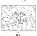
- FIG. 1 illustrates a fuse assembly (hereinafter “assembly”) 100 according to embodiments of the present disclosure.
- the assembly 100 may be secured to a power source 102, such as a battery, which may be used for vehicles or heavy machinery.
- the assembly may include a fusible device (hereinafter “fuse”) 104 coupled to the power source 102 by a conductive component, such as a busbar 106. More specifically, an opening 108 of the busbar 106 may receive a terminal 110 of the power supply 102.
- a fusible device hereinafter "fuse”
- the fuse 104 may be further coupled to a securement device 112, which may be in contact with an upper surface 114 and a side surface 116 of a case 120 of the power source 102 to prevent rotation of the fuse 104 and the busbar 106.
- the assembly may include a cover over the fuse 104.
- the fuse 104 can be a high-current Zcase fuse manufactured by Littelfuse, Inc. In general, the fuse 104 provides protection against overvoltage and/or overcurrent conditions.
- the fuse 102 can include an aperture to accommodate positioning on or around a conductive central support 124.
- the aperture of the fuse 104 can be a central aperture and can be of any size and shape.
- the fuse 104 can further include an input terminal and an output terminal. As an example, a top portion of the fuse 104 can provide the input terminal and a bottom portion of the fuse 104 can provide the output terminal.
- FIGs. 2A and 2B demonstrate the assembly 100 in greater detail.
- the assembly 100 may further include a base member 122 operable to receive the busbar 106.
- the fuse 104, the busbar 106, and the base member 122 may be coupled together by the central support (e.g., stud or screw) 124 and a fastener/nut 126.
- the central support 124 and the nut 126 may be engaged with one another by complimentary threading.
- the fuse 104, the busbar 106, and the base member 122 may be received within a recess 128 of a body 130 of the securement device 112.
- the recess 128 may be defined, in part, by one or more sidewalls 132 extending along a perimeter of the body 130.
- the body 130 may include a plurality of fasteners 169, such as press-fit or snap-fit tabs, extending above the recess 128.
- the fasteners 169 may be operable to engage an upper wall or surface 136 of the base member 122 to retain the two components together.
- the body 130 and the base member 122 may be clipped on during installation.
- the securement device 112 may include a support post 140 and a wall 180 extending from the body 130.
- the support post 140 and the wall 180 are operable to engage the case 120 ( FIG. 1 ) of the power source 102 to restrict rotation of the busbar 106 and the fuse 104 relative to the case 120.
- the base member 122 may include a base body 139 having a first end 141 opposite a second end 142, a first side 143 opposite a second side 144, and an interior surface 145 opposite an exterior surface 146.
- the interior surface 145 may be adjacent to, and/or in direct contact with, the busbar 106, while the exterior surface 146 may be adjacent to and/or in direct contact with the securement device 112.
- the features defining the exterior surface 146 may generally complement the surfaces or features defining the recess 128 of the body 130 of the securement device 112.
- the base member 122 may include a central cylinder 147 defining an opening 148 operable to receive the central support 124.
- the base member 122 may further include a plurality of fasteners 149, such as press-fit or snap-fit tabs.
- each of the fasteners 149 may include a sloped engagement surface 150 extending to a retention surface 151.
- the busbar 106 may be forced against each engagement surface 150, which causes the fasteners 149 to deflect away from the central cylinder 147.
- the fasteners 149 will relax and move towards the central cylinder 147 until a top surface of the busbar 106 is adjacent to, or in contact with, the retention surface 151.
- the retention surface 151 in abutment with the top surface of the busbar 106 maintains the busbar 106 within an internal area 153 of the base member 122.
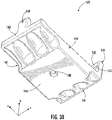
- the body 130 of the securement device 112 may include a first end 161 opposite a second end 162, a first side 163 opposite a second side 164, and first main surface 165 opposite a second main surface 166.
- the first main surface 165 may generally correspond to an upper side of the body 130, while the second main surface 166 may generally correspond to a lower or underside of the body 130.
- the securement device 112 may be made from a non-conductive material.
- the securement device 112 includes the plurality of fasteners 169, such as press-fit or snap-fit tabs.
- each of the fasteners 169 may include a sloped engagement surface 170 extending to a retention surface 171.
- the base member 122 which is secured to the fuse 104 and the busbar 106, may be forced against each engagement surface 170, which causes the fasteners 169 to deflect outwardly from the recess 128.
- the fasteners 169 will relax and move back towards an original position until the top surface 136 of the base member 122 is adjacent to, or in contact with, the retention surface 171.
- the retention surface 171 in abutment with the top surface 136 of the base member 122 maintains the fuse 104 within the recess 128 of the base member 122.
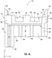
- the fasteners 169 extend upwardly from the sidewall 132 of the body 130 (e.g., along the y-direction).
- the sidewall 132 may further include one or more openings 174 operable to receive tabs 175 ( FIGs. 2A-2B ) of the busbar 106.
- the sidewall 132 may extend farther from the fuse 104 (e.g., along the z-direction) than the tabs 175 of the busbar 106 to protect the busbar 106 from inadvertently making contact with conductive components in close proximity thereto.
- the securement device 112 may further include the wall 180 extending from the body 130. More specifically, the wall 180 may be coupled to, or integrally formed with, the second main surface 166.
- the wall 180 may generally extend perpendicular from a plane (e.g., x-z plane) defined by the second main surface 166.
- the wall 180 may include a main section 181 having a first wall end 182 opposite a second wall end 183.
- the main section 181 may include one or more support ribs 184 connected with the second main surface 166. In some embodiments, the support ribs 184 may extend to a free edge 185 of the main section 181.
- the wall 180 may be integrally formed with the support post 140. In other embodiments, the wall 180 and the support post 140 are separated from one another by a gap.
- the first wall end 182 may be offset (e.g., along the z-direction) relative to the second wall end 183 such that a first distance 'D1' between the first wall end 182 and the first side 163 of the body 130 is different (e.g., less) than a second distance 'D2' between the second wall end 183 and the first side 163 of the body 130. Additionally, a distance 'PD' between the support post 140 and the first side 163 of the body 130 may be less than D1 and D2. As a result, various battery tolerances can be accommodated by a same securement device 112.
- FIG. 5 shows the support post 140 in direct contact with the side surface 116 of the case 120 in position (a).
- the support post 140 disengages from the side surface 116, while the second wall end 183 begins to rotate/move towards the side surface 116.
- a gap 'G' between the support post 140 and the side surface 116 may be approximately equal to the distance between the wall 180 and the side surface 116.
- the gap allows the securement device 112 to be mounted to batteries with various dimensions.
- the securement device 112 may then continue to rotate until second wall end 183 directly engages the side surface 116.
- the wall 180 restricts further movement of the fuse 104 and the busbar 106 during torqueing and/or vibration.
- a free end 186 of the support post 140 may extend down from the second main surface 166 by a third distance 'D3', while the free edge 185 of the wall 180 may extend down from the second main surface 166 by a fourth distance 'D4'.
- D3 and D4 may be equal. Making the support post 140 longer than the wall 180 may ensure contact between the support post 140 and the case 120 of the power supply 102 should the fuse 104 and securement device 112 rotate slightly.
- the terms “substantial” or “substantially,” as well as the terms “approximate” or “approximately,” can be used interchangeably in some embodiments, and can be described using any relative measures acceptable by one of ordinary skill in the art. For example, these terms can serve as a comparison to a reference parameter, to indicate a deviation capable of providing the intended function. Although non-limiting, the deviation from the reference parameter can be, for example, in an amount of less than 1%, less than 3%, less than 5%, less than 10%, less than 15%, less than 20%, and so on.
Landscapes
- Engineering & Computer Science (AREA)
- Power Engineering (AREA)
- Fuses (AREA)
Abstract
Description
- The disclosure relates generally to the field of circuit protection devices and, more particularly, to a fuse assembly including an anti-rotation device.
- Fuses are used as a circuit protection device and can provide an electrical connection between a power source and a circuit to be protected. Fuses can be designed to provide protection to the circuit during an overcurrent and/or an overvoltage condition. In particular, the fuse can be constructed to physically open or interrupt the electrical connection when a specified overcurrent and/or an overvoltage condition occurs, thereby isolating the circuit and preventing damage.
- In the automotive market there has been a trend toward implementing so-called "pre-fuse boxes" that are disposed within automobile engine compartments and connected to automobile battery terminals. The primary purpose of a pre-fuse box in an automobile is to prevent electrical damage that may result from short-circuiting in high-current-conducting wires, such as may occur in the event of an accident. In some examples, the fuse may be connected to the battery terminal by a busbar and a central post (e.g., stud or screw) coupled to the fuse element. The central post may be tightened or loosened (e.g., via a nut) to attach and detach the pre-fuse box. However, even after the central post has been secured into place, vibration to the battery may cause the fuse and the busbar to rotate and potentially touch other nearby components, which could cause a short circuit.
- Accordingly, there is a need to prevent rotation of the pre-fuse box relative to the power source.
- This Summary is provided to introduce a selection of concepts in a simplified form that are further described below in the Detailed Description. This Summary is not intended to identify key features or essential features of the claimed subject matter, nor is it intended as an aid in determining the scope of the claimed subject matter.
- In one approach according to the present disclosure, a fuse assembly may include a fusible device connected to a conductive component, wherein the conductive component is operable to connect to a terminal of a power source. The fuse assembly further includes a securement device coupled to the fusible device. The securement device may include a body including a recess operable to receive the fusible device, and a support post extending from the body, wherein the support post is operable to engage the power source to reduce rotation of the securement device and the fusible device relative to the power source.
- In another approach of the disclosure, a securement device may include a body including a first end opposite a second end, a first side opposite a second side, and a first main side opposite a second main side, wherein the first main side is operable to receive a fusible device within a recess. The securement device may further include a wall extending from the second main side of the body, wherein the wall includes a first wall end and a second wall end, and wherein the first wall end and the second wall end are offset relative to one another such that a first distance between the first wall end and the first side of the body is different than a second distance between the second wall end and the first side of the body.
- In yet another approach of the present disclosure, a fuse assembly may include a fusible device connected to a busbar and base member by a central support, wherein the conductive component is operable to connect to a terminal of a battery, and a securement device coupled to the fusible device. The securement device may include a body including a recess operable to receive the fusible device, and a support post extending from the body, wherein the support post is operable to engage a case of the battery to reduce rotation of the securement device and the fusible device relative to the battery.
- The accompanying drawings illustrate exemplary approaches of the disclosed embodiments so far devised for the practical application of the principles thereof, and in which:
-
FIG. 1 depicts a perspective view of a fuse assembly and power source according to embodiments of the present disclosure; -
FIG. 2A depicts a partially exploded perspective view of the fuse assembly according to embodiments of the present disclosure; -
FIG. 2B depicts a perspective view of the fuse assembly according to embodiments of the present disclosure; -
FIG. 3A depicts a first perspective view of a base member of the fuse assembly according to embodiments of the present disclosure; -
FIG. 3B depicts a second perspective view of a base member of the fuse assembly according to embodiments of the present disclosure; -
FIG. 4A depicts a side view of a securement device of the fuse assembly according to embodiments of the present disclosure; -
FIG. 4B depicts an end view of the securement device of the fuse assembly according to embodiments of the present disclosure; -
FIG. 4C depicts a bottom view of the securement device of the fuse assembly according to embodiments of the present disclosure; and -
FIG. 5 depicts side views of the securement device according to embodiments of the present disclosure. - The drawings are not necessarily to scale. The drawings are merely representations, not intended to portray specific parameters of the disclosure. The drawings are intended to depict typical embodiments of the disclosure, and therefore should not be considered as limiting in scope. In the drawings, like numbering represents like elements.
- Furthermore, certain elements in some of the figures may be omitted, or illustrated not-to-scale, for illustrative clarity. Furthermore, for clarity, some reference numbers may be omitted in certain drawings.
- Embodiments in accordance with the present disclosure will now be described more fully hereinafter with reference to the accompanying drawings. The assemblies, components thereof, and methods may be embodied in many different forms and should not be construed as being limited to the embodiments set forth herein. Rather, these embodiments are provided so that this disclosure will be thorough and complete, and will fully convey the scope of the assemblies, components, and methods to those skilled in the art.
-
FIG. 1 illustrates a fuse assembly (hereinafter "assembly") 100 according to embodiments of the present disclosure. Theassembly 100 may be secured to apower source 102, such as a battery, which may be used for vehicles or heavy machinery. In some embodiments, the assembly may include a fusible device (hereinafter "fuse") 104 coupled to thepower source 102 by a conductive component, such as abusbar 106. More specifically, anopening 108 of thebusbar 106 may receive aterminal 110 of thepower supply 102. As will be described in greater detail herein, thefuse 104 may be further coupled to asecurement device 112, which may be in contact with an upper surface 114 and aside surface 116 of acase 120 of thepower source 102 to prevent rotation of thefuse 104 and thebusbar 106. Although not shown, the assembly may include a cover over thefuse 104. - As an example, the
fuse 104 can be a high-current Zcase fuse manufactured by Littelfuse, Inc. In general, thefuse 104 provides protection against overvoltage and/or overcurrent conditions. Thefuse 102 can include an aperture to accommodate positioning on or around a conductivecentral support 124. The aperture of thefuse 104 can be a central aperture and can be of any size and shape. Thefuse 104 can further include an input terminal and an output terminal. As an example, a top portion of thefuse 104 can provide the input terminal and a bottom portion of thefuse 104 can provide the output terminal. -
FIGs. 2A and2B demonstrate theassembly 100 in greater detail. As shown, theassembly 100 may further include abase member 122 operable to receive thebusbar 106. Thefuse 104, thebusbar 106, and thebase member 122 may be coupled together by the central support (e.g., stud or screw) 124 and a fastener/nut 126. In some embodiments, thecentral support 124 and thenut 126 may be engaged with one another by complimentary threading. - The
fuse 104, thebusbar 106, and thebase member 122 may be received within arecess 128 of abody 130 of thesecurement device 112. Therecess 128 may be defined, in part, by one or more sidewalls 132 extending along a perimeter of thebody 130. In some embodiments, thebody 130 may include a plurality offasteners 169, such as press-fit or snap-fit tabs, extending above therecess 128. Thefasteners 169 may be operable to engage an upper wall orsurface 136 of thebase member 122 to retain the two components together. Advantageously, thebody 130 and thebase member 122 may be clipped on during installation. As will be described in greater detail herein, thesecurement device 112 may include asupport post 140 and awall 180 extending from thebody 130. Thesupport post 140 and thewall 180 are operable to engage the case 120 (FIG. 1 ) of thepower source 102 to restrict rotation of thebusbar 106 and thefuse 104 relative to thecase 120. - Turning now to
FIGs. 3A-3B , thebase member 122 according to embodiments of the present disclosure will be described in greater detail. As shown, thebase member 122 may include abase body 139 having afirst end 141 opposite asecond end 142, afirst side 143 opposite asecond side 144, and aninterior surface 145 opposite anexterior surface 146. Theinterior surface 145 may be adjacent to, and/or in direct contact with, thebusbar 106, while theexterior surface 146 may be adjacent to and/or in direct contact with thesecurement device 112. Although not limited to any particular shape or configuration, the features defining theexterior surface 146 may generally complement the surfaces or features defining therecess 128 of thebody 130 of thesecurement device 112. - As further shown, the
base member 122 may include acentral cylinder 147 defining anopening 148 operable to receive thecentral support 124. In some embodiments, thebase member 122 may further include a plurality offasteners 149, such as press-fit or snap-fit tabs. As shown, each of thefasteners 149 may include a slopedengagement surface 150 extending to aretention surface 151. During assembly, thebusbar 106 may be forced against eachengagement surface 150, which causes thefasteners 149 to deflect away from thecentral cylinder 147. As thebusbar 106 is depressed beyond eachengagement surface 150, thefasteners 149 will relax and move towards thecentral cylinder 147 until a top surface of thebusbar 106 is adjacent to, or in contact with, theretention surface 151. Theretention surface 151 in abutment with the top surface of thebusbar 106 maintains thebusbar 106 within aninternal area 153 of thebase member 122. - Turning now to
FIGs. 4A-4C , thesecurement device 112 according to embodiments of the present disclosure will be described in greater detail. As shown, thebody 130 of thesecurement device 112 may include afirst end 161 opposite asecond end 162, afirst side 163 opposite asecond side 164, and firstmain surface 165 opposite a secondmain surface 166. The firstmain surface 165 may generally correspond to an upper side of thebody 130, while the secondmain surface 166 may generally correspond to a lower or underside of thebody 130. Although not limited to any particular material, thesecurement device 112 may be made from a non-conductive material. - In some embodiments, the
securement device 112 includes the plurality offasteners 169, such as press-fit or snap-fit tabs. As shown, each of thefasteners 169 may include a slopedengagement surface 170 extending to aretention surface 171. During assembly, thebase member 122, which is secured to thefuse 104 and thebusbar 106, may be forced against eachengagement surface 170, which causes thefasteners 169 to deflect outwardly from therecess 128. As thebase member 122 is depressed beyond eachengagement surface 170, thefasteners 169 will relax and move back towards an original position until thetop surface 136 of thebase member 122 is adjacent to, or in contact with, theretention surface 171. Theretention surface 171 in abutment with thetop surface 136 of thebase member 122 maintains thefuse 104 within therecess 128 of thebase member 122. - In some embodiments, the
fasteners 169 extend upwardly from thesidewall 132 of the body 130 (e.g., along the y-direction). As best shown inFIG. 4A , thesidewall 132 may further include one ormore openings 174 operable to receive tabs 175 (FIGs. 2A-2B ) of thebusbar 106. Advantageously, thesidewall 132 may extend farther from the fuse 104 (e.g., along the z-direction) than thetabs 175 of thebusbar 106 to protect thebusbar 106 from inadvertently making contact with conductive components in close proximity thereto. - The
securement device 112 may further include thewall 180 extending from thebody 130. More specifically, thewall 180 may be coupled to, or integrally formed with, the secondmain surface 166. Thewall 180 may generally extend perpendicular from a plane (e.g., x-z plane) defined by the secondmain surface 166. Although not limited to any particular shape or configuration, thewall 180 may include amain section 181 having afirst wall end 182 opposite asecond wall end 183. Themain section 181 may include one ormore support ribs 184 connected with the secondmain surface 166. In some embodiments, thesupport ribs 184 may extend to afree edge 185 of themain section 181. In some embodiments, thewall 180 may be integrally formed with thesupport post 140. In other embodiments, thewall 180 and thesupport post 140 are separated from one another by a gap. - As best demonstrated in
FIG. 4C , thefirst wall end 182 may be offset (e.g., along the z-direction) relative to thesecond wall end 183 such that a first distance 'D1' between thefirst wall end 182 and thefirst side 163 of thebody 130 is different (e.g., less) than a second distance 'D2' between thesecond wall end 183 and thefirst side 163 of thebody 130. Additionally, a distance 'PD' between thesupport post 140 and thefirst side 163 of thebody 130 may be less than D1 and D2. As a result, various battery tolerances can be accommodated by asame securement device 112. - This is further demonstrated in
FIG. 5 , which shows thesupport post 140 in direct contact with theside surface 116 of thecase 120 in position (a). As thesecurement device 112 rotates to position (b), thesupport post 140 disengages from theside surface 116, while thesecond wall end 183 begins to rotate/move towards theside surface 116. In position (c), a gap 'G' between thesupport post 140 and theside surface 116 may be approximately equal to the distance between thewall 180 and theside surface 116. The gap allows thesecurement device 112 to be mounted to batteries with various dimensions. Thesecurement device 112 may then continue to rotate untilsecond wall end 183 directly engages theside surface 116. Thewall 180 restricts further movement of thefuse 104 and thebusbar 106 during torqueing and/or vibration. - Referring again to
FIG. 4A , afree end 186 of thesupport post 140 may extend down from the secondmain surface 166 by a third distance 'D3', while thefree edge 185 of thewall 180 may extend down from the secondmain surface 166 by a fourth distance 'D4'. As shown, D3 > D4. In other embodiments, D3 and D4 may be equal. Making thesupport post 140 longer than thewall 180 may ensure contact between thesupport post 140 and thecase 120 of thepower supply 102 should thefuse 104 andsecurement device 112 rotate slightly. - For the sake of convenience and clarity, terms such as "top," "bottom," "upper," "lower," "vertical," "horizontal," "lateral," and "longitudinal" are used herein to describe the relative placement and orientation of components and their constituent parts as appearing in the figures. The terminology will include the words specifically mentioned, derivatives thereof, and words of similar import.
- As used herein, an element or operation recited in the singular and proceeded with the word "a" or "an" is to be understood as including plural elements or operations, until such exclusion is explicitly recited. Furthermore, references to "one embodiment" of the present disclosure are not intended as limiting. Additional embodiments may also incorporating the recited features.
- Furthermore, the terms "substantial" or "substantially," as well as the terms "approximate" or "approximately," can be used interchangeably in some embodiments, and can be described using any relative measures acceptable by one of ordinary skill in the art. For example, these terms can serve as a comparison to a reference parameter, to indicate a deviation capable of providing the intended function. Although non-limiting, the deviation from the reference parameter can be, for example, in an amount of less than 1%, less than 3%, less than 5%, less than 10%, less than 15%, less than 20%, and so on.
- Still furthermore, one of skill will understand when an element or component is referred to as being formed on, deposited on, or disposed "on," "over" or "atop" another element, the element can be directly on the other element or intervening elements may also be present. In contrast, when an element is referred to as being "directly on," "directly over" or "directly atop" another element, no intervening elements are present.
- The present disclosure is not to be limited in scope by the specific embodiments described herein. Indeed, other various embodiments of and modifications to the present disclosure, in addition to those described herein, will be apparent to those of ordinary skill in the art from the foregoing description and accompanying drawings. Thus, such other embodiments and modifications are intended to fall within the scope of the present disclosure. Furthermore, the present disclosure has been described herein in the context of a particular implementation in a particular environment for a particular purpose. Those of ordinary skill in the art will recognize the usefulness is not limited thereto and the present disclosure may be beneficially implemented in any number of environments for any number of purposes. Thus, the claims set forth below are to be construed in view of the full breadth and spirit of the present disclosure as described herein.
Claims (15)
- A fuse assembly, comprising:a fusible device connected to a conductive component, wherein the conductive component is operable to connect to a terminal of a power source; anda securement device coupled to the fusible device, the securement device comprising:a body including a recess operable to receive the fusible device; anda support post extending from the body, wherein the support post isoperable to engage the power source to reduce rotation of the securement device and the fusible device relative to the power source.
- The fuse assembly of claim 1, further comprising a base member coupled to the conductive component and to the body of the securement device, preferably further comprising a central support coupling together the fusible device, the conductive component, and the base member.
- The fuse assembly of claim 2, wherein the body of the securement device comprises:a first end opposite a second end, and a first side opposite a second side;a sidewall extending along at least one of the first side or the second side, wherein the sidewall comprises an opening operable to receive a tab of the conductive component; anda plurality of fasteners extending from the sidewall, wherein the plurality of fasteners are coupled to the base member, preferably wherein one or more of the plurality of fasteners is a press-fit tab comprising a sloped engagement surface and a retention surface, and wherein the retention surface is operable to engage an upper surface of the base member.
- The fuse assembly of any of the preceding claims wherein the securement device further comprises a wall extending from the body, wherein the wall includes a first wall end and a second wall end, and wherein the first wall end and the second wall end are offset relative to one another such that a first distance between the first wall end and the first side of the body is different than a second distance between the second wall end and the first side of the body.
- The fuse assembly of claim 4, wherein the wall is connected to the support post, and wherein the wall extends perpendicular to a plane defined by a lower surface of the body of the securement device, and/or wherein a free end of the support post extends below the body by a third distance, wherein a free edge of the wall extends below the body by a fourth distance, and wherein the third distance is greater than the fourth distance.
- The fuse assembly of any of the preceding claims wherein the conductive component is a busbar, wherein the power source is a battery comprising a battery case directly adjacent the support post, and wherein the busbar comprises an opening for receiving the terminal of the battery.
- A securement device, preferably for a fuse assembly according to any of the preceding claims, comprising:a body including a first end opposite a second end, a first side opposite a second side, and a first main side opposite a second main side, wherein the first main side is operable to receive a fusible device within a recess; andwall extending from the second main side of the body, wherein the wall includes a first wall end and a second wall end, and wherein the first wall end and the second wall end are offset relative to one another such that a first distance between the first wall end and the first side of the body is different than a second distance between the second wall end and the first side of the body.
- The securement device of claim 7, further comprising a support post extending from the second main side of the body, wherein the support post is operable to engage a power source to reduce rotation of the body and the fusible device relative to the power source.
- The securement device of claim 7 or 8, wherein the body of the securement device comprises:a sidewall extending along at least one of the first side or the second side, wherein the sidewall comprises an opening operable to receive a tab of a busbar coupled to the fusible device; anda plurality of fasteners extending from the sidewall, preferably wherein one or more of the plurality of fasteners is a press-fit tab comprising a sloped engagement surface and a retention surface, and wherein the retention surface is operable to engage an upper surface of a base member coupled to the fusible device.
- The securement device of any of the claims 8 or 9 wherein the wall is connected to the support post, and wherein the wall extends perpendicular to a plane defined by the second main side of the body.
- The securement device of any of the claims 8-10, wherein a free end of the support post extends below the body by a third distance, wherein a free edge of the wall extends below the body by a fourth distance, and wherein the third distance is greater than the fourth distance.
- A fuse assembly, comprising:a fusible device connected to a busbar and base member by a central support, wherein the busbar is operable to connect to a terminal of a battery; anda securement device coupled to the fusible device, the securement device comprising:a body including a recess operable to receive the fusible device; anda support post extending from the body, wherein the support post is operable to engage a case of the battery to reduce rotation of the securement device and the fusible device relative to the battery.
- The fuse assembly of claim 12, wherein the body of the securement device comprises:a first end opposite a second end, and a first side opposite a second side;a sidewall extending along at least one of the first side or the second side, wherein the sidewall comprises an opening operable to receive a tab of the busbar; anda plurality of press-fit tabs extending from the sidewall, wherein the plurality of press-fit tabs are coupleable with the base member.
- The fuse assembly of claim 13, wherein the securement device further comprises a wall extending from the body, wherein the wall includes a first wall end and a second wall end, and wherein the first wall end and the second wall end are offset relative to one another such that a first distance between the first wall end and the first side of the body is different than a second distance between the second wall end and the first side of the body.
- The fuse assembly of claim 14, wherein the wall is connected to the support post, and wherein the wall extends perpendicular to a plane defined by a lower surface of the body of the securement device and/or wherein a free end of the support post extends below the body by a third distance, wherein a free edge of the wall extends below the body by a fourth distance, and wherein the third distance is greater than the fourth distance.
Applications Claiming Priority (1)
| Application Number | Priority Date | Filing Date | Title |
|---|---|---|---|
| US17/395,757 US12020882B2 (en) | 2021-08-06 | 2021-08-06 | Fuse assembly including anti-rotation device |
Publications (3)
| Publication Number | Publication Date |
|---|---|
| EP4131318A2 true EP4131318A2 (en) | 2023-02-08 |
| EP4131318A3 EP4131318A3 (en) | 2023-04-05 |
| EP4131318B1 EP4131318B1 (en) | 2025-07-23 |
Family
ID=82608019
Family Applications (1)
| Application Number | Title | Priority Date | Filing Date |
|---|---|---|---|
| EP22185057.1A Active EP4131318B1 (en) | 2021-08-06 | 2022-07-14 | Fuse assembly including anti-rotation device |
Country Status (3)
| Country | Link |
|---|---|
| US (1) | US12020882B2 (en) |
| EP (1) | EP4131318B1 (en) |
| CN (1) | CN115910720A (en) |
Family Cites Families (10)
| Publication number | Priority date | Publication date | Assignee | Title |
|---|---|---|---|---|
| JP4083991B2 (en) | 2000-02-09 | 2008-04-30 | 矢崎総業株式会社 | Fuse unit and manufacturing method thereof |
| JP4959507B2 (en) * | 2007-10-31 | 2012-06-27 | 矢崎総業株式会社 | Assembly structure of fusible link unit |
| JP5189920B2 (en) * | 2008-07-25 | 2013-04-24 | 矢崎総業株式会社 | Fusible link unit |
| JP5448469B2 (en) * | 2009-01-23 | 2014-03-19 | 矢崎総業株式会社 | Fusible link connection structure |
| JP5422429B2 (en) | 2010-02-10 | 2014-02-19 | 矢崎総業株式会社 | Fuse unit |
| JP5505113B2 (en) * | 2010-06-15 | 2014-05-28 | 住友電装株式会社 | Fuse unit for directly attaching battery terminals |
| JP6178652B2 (en) | 2013-07-26 | 2017-08-09 | 矢崎総業株式会社 | cover |
| JP6232001B2 (en) * | 2015-01-14 | 2017-11-15 | 矢崎総業株式会社 | Fuse unit |
| JP7033595B2 (en) * | 2016-12-05 | 2022-03-10 | リテルヒューズ・インク | Battery terminal fuse module |
| JP6790021B2 (en) * | 2018-05-09 | 2020-11-25 | 矢崎総業株式会社 | Battery terminal with fuse holder |
-
2021
- 2021-08-06 US US17/395,757 patent/US12020882B2/en active Active
-
2022
- 2022-07-14 EP EP22185057.1A patent/EP4131318B1/en active Active
- 2022-08-05 CN CN202210937951.6A patent/CN115910720A/en active Pending
Also Published As
| Publication number | Publication date |
|---|---|
| US20230037990A1 (en) | 2023-02-09 |
| EP4131318B1 (en) | 2025-07-23 |
| EP4131318A3 (en) | 2023-04-05 |
| CN115910720A (en) | 2023-04-04 |
| US12020882B2 (en) | 2024-06-25 |
Similar Documents
| Publication | Publication Date | Title |
|---|---|---|
| US12355108B2 (en) | Inter-terminal connection structure | |
| US10510507B2 (en) | Fuse unit | |
| US7192319B1 (en) | Insulated cable termination assembly and method of fabrication | |
| US20120309239A1 (en) | Protective cap for prevention of oblique tightening of fusible link directly mounted on battery | |
| WO2016114069A1 (en) | Fuse unit | |
| US20140374139A1 (en) | Booster cable holding structure | |
| US11025016B2 (en) | Electrical assembly to prevent improper installation | |
| US12020882B2 (en) | Fuse assembly including anti-rotation device | |
| EP3685418B1 (en) | Integrated fuse module | |
| AU2018201864B2 (en) | High amp circuit breaker with terminal isolation fastener cap | |
| KR101984883B1 (en) | Secondary battery | |
| JP2002133979A (en) | Safety plug box | |
| US20210296797A1 (en) | Terminal cap | |
| US20230162940A1 (en) | Fuse module with clamped fuse installation | |
| JP7845924B2 (en) | Energy storage device | |
| US20250007224A1 (en) | Through-aperture electrical connector | |
| US20250191867A1 (en) | Jump stud fuse module | |
| JP6643889B2 (en) | Fusible link unit | |
| US20240332934A1 (en) | Junction box assembly with recessed key features | |
| JP2026067455A (en) | Electrical connection unit | |
| JP2026067495A (en) | Electrical connection unit | |
| JP2025172439A (en) | Terminal connection structure | |
| JP2024150191A (en) | Fuse unit protective cover | |
| JP2022139670A (en) | Busbar protector and busbar with protector |
Legal Events
| Date | Code | Title | Description |
|---|---|---|---|
| PUAI | Public reference made under article 153(3) epc to a published international application that has entered the european phase |
Free format text: ORIGINAL CODE: 0009012 |
|
| STAA | Information on the status of an ep patent application or granted ep patent |
Free format text: STATUS: THE APPLICATION HAS BEEN PUBLISHED |
|
| AK | Designated contracting states |
Kind code of ref document: A2 Designated state(s): AL AT BE BG CH CY CZ DE DK EE ES FI FR GB GR HR HU IE IS IT LI LT LU LV MC MK MT NL NO PL PT RO RS SE SI SK SM TR |
|
| PUAL | Search report despatched |
Free format text: ORIGINAL CODE: 0009013 |
|
| AK | Designated contracting states |
Kind code of ref document: A3 Designated state(s): AL AT BE BG CH CY CZ DE DK EE ES FI FR GB GR HR HU IE IS IT LI LT LU LV MC MK MT NL NO PL PT RO RS SE SI SK SM TR |
|
| RIC1 | Information provided on ipc code assigned before grant |
Ipc: H01H 85/02 20060101AFI20230224BHEP |
|
| STAA | Information on the status of an ep patent application or granted ep patent |
Free format text: STATUS: REQUEST FOR EXAMINATION WAS MADE |
|
| 17P | Request for examination filed |
Effective date: 20231004 |
|
| RBV | Designated contracting states (corrected) |
Designated state(s): AL AT BE BG CH CY CZ DE DK EE ES FI FR GB GR HR HU IE IS IT LI LT LU LV MC MK MT NL NO PL PT RO RS SE SI SK SM TR |
|
| STAA | Information on the status of an ep patent application or granted ep patent |
Free format text: STATUS: EXAMINATION IS IN PROGRESS |
|
| 17Q | First examination report despatched |
Effective date: 20240422 |
|
| GRAP | Despatch of communication of intention to grant a patent |
Free format text: ORIGINAL CODE: EPIDOSNIGR1 |
|
| STAA | Information on the status of an ep patent application or granted ep patent |
Free format text: STATUS: GRANT OF PATENT IS INTENDED |
|
| INTG | Intention to grant announced |
Effective date: 20250217 |
|
| GRAS | Grant fee paid |
Free format text: ORIGINAL CODE: EPIDOSNIGR3 |
|
| GRAA | (expected) grant |
Free format text: ORIGINAL CODE: 0009210 |
|
| STAA | Information on the status of an ep patent application or granted ep patent |
Free format text: STATUS: THE PATENT HAS BEEN GRANTED |
|
| AK | Designated contracting states |
Kind code of ref document: B1 Designated state(s): AL AT BE BG CH CY CZ DE DK EE ES FI FR GB GR HR HU IE IS IT LI LT LU LV MC MK MT NL NO PL PT RO RS SE SI SK SM TR |
|
| REG | Reference to a national code |
Ref country code: GB Ref legal event code: FG4D |
|
| REG | Reference to a national code |
Ref country code: CH Ref legal event code: EP |
|
| P01 | Opt-out of the competence of the unified patent court (upc) registered |
Free format text: CASE NUMBER: APP_31436/2025 Effective date: 20250630 |
|
| REG | Reference to a national code |
Ref country code: IE Ref legal event code: FG4D |
|
| REG | Reference to a national code |
Ref country code: DE Ref legal event code: R096 Ref document number: 602022017932 Country of ref document: DE |
|
| REG | Reference to a national code |
Ref country code: NL Ref legal event code: MP Effective date: 20250723 |
|
| PG25 | Lapsed in a contracting state [announced via postgrant information from national office to epo] |
Ref country code: PT Free format text: LAPSE BECAUSE OF FAILURE TO SUBMIT A TRANSLATION OF THE DESCRIPTION OR TO PAY THE FEE WITHIN THE PRESCRIBED TIME-LIMIT Effective date: 20251124 |
|
| PG25 | Lapsed in a contracting state [announced via postgrant information from national office to epo] |
Ref country code: NL Free format text: LAPSE BECAUSE OF FAILURE TO SUBMIT A TRANSLATION OF THE DESCRIPTION OR TO PAY THE FEE WITHIN THE PRESCRIBED TIME-LIMIT Effective date: 20250723 |
|
| REG | Reference to a national code |
Ref country code: AT Ref legal event code: MK05 Ref document number: 1817357 Country of ref document: AT Kind code of ref document: T Effective date: 20250723 |
|
| PG25 | Lapsed in a contracting state [announced via postgrant information from national office to epo] |
Ref country code: IS Free format text: LAPSE BECAUSE OF FAILURE TO SUBMIT A TRANSLATION OF THE DESCRIPTION OR TO PAY THE FEE WITHIN THE PRESCRIBED TIME-LIMIT Effective date: 20251123 |
|
| PG25 | Lapsed in a contracting state [announced via postgrant information from national office to epo] |
Ref country code: NO Free format text: LAPSE BECAUSE OF FAILURE TO SUBMIT A TRANSLATION OF THE DESCRIPTION OR TO PAY THE FEE WITHIN THE PRESCRIBED TIME-LIMIT Effective date: 20251023 |
|
| REG | Reference to a national code |
Ref country code: LT Ref legal event code: MG9D |
|
| PG25 | Lapsed in a contracting state [announced via postgrant information from national office to epo] |
Ref country code: AT Free format text: LAPSE BECAUSE OF FAILURE TO SUBMIT A TRANSLATION OF THE DESCRIPTION OR TO PAY THE FEE WITHIN THE PRESCRIBED TIME-LIMIT Effective date: 20250723 |
|
| PG25 | Lapsed in a contracting state [announced via postgrant information from national office to epo] |
Ref country code: FI Free format text: LAPSE BECAUSE OF FAILURE TO SUBMIT A TRANSLATION OF THE DESCRIPTION OR TO PAY THE FEE WITHIN THE PRESCRIBED TIME-LIMIT Effective date: 20250723 |
|
| PG25 | Lapsed in a contracting state [announced via postgrant information from national office to epo] |
Ref country code: HR Free format text: LAPSE BECAUSE OF FAILURE TO SUBMIT A TRANSLATION OF THE DESCRIPTION OR TO PAY THE FEE WITHIN THE PRESCRIBED TIME-LIMIT Effective date: 20250723 |
|
| PG25 | Lapsed in a contracting state [announced via postgrant information from national office to epo] |
Ref country code: GR Free format text: LAPSE BECAUSE OF FAILURE TO SUBMIT A TRANSLATION OF THE DESCRIPTION OR TO PAY THE FEE WITHIN THE PRESCRIBED TIME-LIMIT Effective date: 20251024 |
|
| PG25 | Lapsed in a contracting state [announced via postgrant information from national office to epo] |
Ref country code: SE Free format text: LAPSE BECAUSE OF FAILURE TO SUBMIT A TRANSLATION OF THE DESCRIPTION OR TO PAY THE FEE WITHIN THE PRESCRIBED TIME-LIMIT Effective date: 20250723 |
|
| PG25 | Lapsed in a contracting state [announced via postgrant information from national office to epo] |
Ref country code: LV Free format text: LAPSE BECAUSE OF FAILURE TO SUBMIT A TRANSLATION OF THE DESCRIPTION OR TO PAY THE FEE WITHIN THE PRESCRIBED TIME-LIMIT Effective date: 20250723 |
|
| PG25 | Lapsed in a contracting state [announced via postgrant information from national office to epo] |
Ref country code: BG Free format text: LAPSE BECAUSE OF FAILURE TO SUBMIT A TRANSLATION OF THE DESCRIPTION OR TO PAY THE FEE WITHIN THE PRESCRIBED TIME-LIMIT Effective date: 20250723 Ref country code: PL Free format text: LAPSE BECAUSE OF FAILURE TO SUBMIT A TRANSLATION OF THE DESCRIPTION OR TO PAY THE FEE WITHIN THE PRESCRIBED TIME-LIMIT Effective date: 20250723 |
|
| PG25 | Lapsed in a contracting state [announced via postgrant information from national office to epo] |
Ref country code: RS Free format text: LAPSE BECAUSE OF FAILURE TO SUBMIT A TRANSLATION OF THE DESCRIPTION OR TO PAY THE FEE WITHIN THE PRESCRIBED TIME-LIMIT Effective date: 20251023 |
|
| PG25 | Lapsed in a contracting state [announced via postgrant information from national office to epo] |
Ref country code: ES Free format text: LAPSE BECAUSE OF FAILURE TO SUBMIT A TRANSLATION OF THE DESCRIPTION OR TO PAY THE FEE WITHIN THE PRESCRIBED TIME-LIMIT Effective date: 20250723 |
|
| PG25 | Lapsed in a contracting state [announced via postgrant information from national office to epo] |
Ref country code: SM Free format text: LAPSE BECAUSE OF FAILURE TO SUBMIT A TRANSLATION OF THE DESCRIPTION OR TO PAY THE FEE WITHIN THE PRESCRIBED TIME-LIMIT Effective date: 20250723 |
|
| PG25 | Lapsed in a contracting state [announced via postgrant information from national office to epo] |
Ref country code: DK Free format text: LAPSE BECAUSE OF FAILURE TO SUBMIT A TRANSLATION OF THE DESCRIPTION OR TO PAY THE FEE WITHIN THE PRESCRIBED TIME-LIMIT Effective date: 20250723 |
|
| PG25 | Lapsed in a contracting state [announced via postgrant information from national office to epo] |
Ref country code: CZ Free format text: LAPSE BECAUSE OF FAILURE TO SUBMIT A TRANSLATION OF THE DESCRIPTION OR TO PAY THE FEE WITHIN THE PRESCRIBED TIME-LIMIT Effective date: 20250723 |
|
| PG25 | Lapsed in a contracting state [announced via postgrant information from national office to epo] |
Ref country code: EE Free format text: LAPSE BECAUSE OF FAILURE TO SUBMIT A TRANSLATION OF THE DESCRIPTION OR TO PAY THE FEE WITHIN THE PRESCRIBED TIME-LIMIT Effective date: 20250723 Ref country code: SK Free format text: LAPSE BECAUSE OF FAILURE TO SUBMIT A TRANSLATION OF THE DESCRIPTION OR TO PAY THE FEE WITHIN THE PRESCRIBED TIME-LIMIT Effective date: 20250723 |
|
| REG | Reference to a national code |
Ref country code: CH Ref legal event code: W10 Free format text: ST27 STATUS EVENT CODE: U-0-0-W10-W00 (AS PROVIDED BY THE NATIONAL OFFICE) Effective date: 20260507 |