EP4130615B1 - Outdoor unit and refrigeration cycle device - Google Patents
Outdoor unit and refrigeration cycle device Download PDFInfo
- Publication number
- EP4130615B1 EP4130615B1 EP20927414.1A EP20927414A EP4130615B1 EP 4130615 B1 EP4130615 B1 EP 4130615B1 EP 20927414 A EP20927414 A EP 20927414A EP 4130615 B1 EP4130615 B1 EP 4130615B1
- Authority
- EP
- European Patent Office
- Prior art keywords
- refrigerant
- flow path
- controller
- compressor
- temperature
- Prior art date
- Legal status (The legal status is an assumption and is not a legal conclusion. Google has not performed a legal analysis and makes no representation as to the accuracy of the status listed.)
- Active
Links
Images



Classifications
-
- F—MECHANICAL ENGINEERING; LIGHTING; HEATING; WEAPONS; BLASTING
- F25—REFRIGERATION OR COOLING; COMBINED HEATING AND REFRIGERATION SYSTEMS; HEAT PUMP SYSTEMS; MANUFACTURE OR STORAGE OF ICE; LIQUEFACTION SOLIDIFICATION OF GASES
- F25B—REFRIGERATION MACHINES, PLANTS OR SYSTEMS; COMBINED HEATING AND REFRIGERATION SYSTEMS; HEAT PUMP SYSTEMS
- F25B49/00—Arrangement or mounting of control or safety devices
- F25B49/02—Arrangement or mounting of control or safety devices for compression type machines, plants or systems
-
- F—MECHANICAL ENGINEERING; LIGHTING; HEATING; WEAPONS; BLASTING
- F25—REFRIGERATION OR COOLING; COMBINED HEATING AND REFRIGERATION SYSTEMS; HEAT PUMP SYSTEMS; MANUFACTURE OR STORAGE OF ICE; LIQUEFACTION SOLIDIFICATION OF GASES
- F25B—REFRIGERATION MACHINES, PLANTS OR SYSTEMS; COMBINED HEATING AND REFRIGERATION SYSTEMS; HEAT PUMP SYSTEMS
- F25B41/00—Fluid-circulation arrangements
- F25B41/30—Expansion means; Dispositions thereof
- F25B41/39—Dispositions with two or more expansion means arranged in series, i.e. multi-stage expansion, on a refrigerant line leading to the same evaporator
-
- F—MECHANICAL ENGINEERING; LIGHTING; HEATING; WEAPONS; BLASTING
- F25—REFRIGERATION OR COOLING; COMBINED HEATING AND REFRIGERATION SYSTEMS; HEAT PUMP SYSTEMS; MANUFACTURE OR STORAGE OF ICE; LIQUEFACTION SOLIDIFICATION OF GASES
- F25B—REFRIGERATION MACHINES, PLANTS OR SYSTEMS; COMBINED HEATING AND REFRIGERATION SYSTEMS; HEAT PUMP SYSTEMS
- F25B45/00—Arrangements for charging or discharging refrigerant
-
- F—MECHANICAL ENGINEERING; LIGHTING; HEATING; WEAPONS; BLASTING
- F25—REFRIGERATION OR COOLING; COMBINED HEATING AND REFRIGERATION SYSTEMS; HEAT PUMP SYSTEMS; MANUFACTURE OR STORAGE OF ICE; LIQUEFACTION SOLIDIFICATION OF GASES
- F25B—REFRIGERATION MACHINES, PLANTS OR SYSTEMS; COMBINED HEATING AND REFRIGERATION SYSTEMS; HEAT PUMP SYSTEMS
- F25B2400/00—Component parts or details not otherwise provided for in this subclass
- F25B2400/04—Refrigeration circuit bypassing means
-
- F—MECHANICAL ENGINEERING; LIGHTING; HEATING; WEAPONS; BLASTING
- F25—REFRIGERATION OR COOLING; COMBINED HEATING AND REFRIGERATION SYSTEMS; HEAT PUMP SYSTEMS; MANUFACTURE OR STORAGE OF ICE; LIQUEFACTION SOLIDIFICATION OF GASES
- F25B—REFRIGERATION MACHINES, PLANTS OR SYSTEMS; COMBINED HEATING AND REFRIGERATION SYSTEMS; HEAT PUMP SYSTEMS
- F25B2400/00—Component parts or details not otherwise provided for in this subclass
- F25B2400/23—Separators
-
- F—MECHANICAL ENGINEERING; LIGHTING; HEATING; WEAPONS; BLASTING
- F25—REFRIGERATION OR COOLING; COMBINED HEATING AND REFRIGERATION SYSTEMS; HEAT PUMP SYSTEMS; MANUFACTURE OR STORAGE OF ICE; LIQUEFACTION SOLIDIFICATION OF GASES
- F25B—REFRIGERATION MACHINES, PLANTS OR SYSTEMS; COMBINED HEATING AND REFRIGERATION SYSTEMS; HEAT PUMP SYSTEMS
- F25B2600/00—Control issues
- F25B2600/25—Control of valves
- F25B2600/2509—Economiser valves
-
- F—MECHANICAL ENGINEERING; LIGHTING; HEATING; WEAPONS; BLASTING
- F25—REFRIGERATION OR COOLING; COMBINED HEATING AND REFRIGERATION SYSTEMS; HEAT PUMP SYSTEMS; MANUFACTURE OR STORAGE OF ICE; LIQUEFACTION SOLIDIFICATION OF GASES
- F25B—REFRIGERATION MACHINES, PLANTS OR SYSTEMS; COMBINED HEATING AND REFRIGERATION SYSTEMS; HEAT PUMP SYSTEMS
- F25B2600/00—Control issues
- F25B2600/25—Control of valves
- F25B2600/2513—Expansion valves
-
- F—MECHANICAL ENGINEERING; LIGHTING; HEATING; WEAPONS; BLASTING
- F25—REFRIGERATION OR COOLING; COMBINED HEATING AND REFRIGERATION SYSTEMS; HEAT PUMP SYSTEMS; MANUFACTURE OR STORAGE OF ICE; LIQUEFACTION SOLIDIFICATION OF GASES
- F25B—REFRIGERATION MACHINES, PLANTS OR SYSTEMS; COMBINED HEATING AND REFRIGERATION SYSTEMS; HEAT PUMP SYSTEMS
- F25B2600/00—Control issues
- F25B2600/25—Control of valves
- F25B2600/2523—Receiver valves
-
- F—MECHANICAL ENGINEERING; LIGHTING; HEATING; WEAPONS; BLASTING
- F25—REFRIGERATION OR COOLING; COMBINED HEATING AND REFRIGERATION SYSTEMS; HEAT PUMP SYSTEMS; MANUFACTURE OR STORAGE OF ICE; LIQUEFACTION SOLIDIFICATION OF GASES
- F25B—REFRIGERATION MACHINES, PLANTS OR SYSTEMS; COMBINED HEATING AND REFRIGERATION SYSTEMS; HEAT PUMP SYSTEMS
- F25B2700/00—Sensing or detecting of parameters; Sensors therefor
- F25B2700/19—Pressures
- F25B2700/193—Pressures of the compressor
- F25B2700/1931—Discharge pressures
-
- F—MECHANICAL ENGINEERING; LIGHTING; HEATING; WEAPONS; BLASTING
- F25—REFRIGERATION OR COOLING; COMBINED HEATING AND REFRIGERATION SYSTEMS; HEAT PUMP SYSTEMS; MANUFACTURE OR STORAGE OF ICE; LIQUEFACTION SOLIDIFICATION OF GASES
- F25B—REFRIGERATION MACHINES, PLANTS OR SYSTEMS; COMBINED HEATING AND REFRIGERATION SYSTEMS; HEAT PUMP SYSTEMS
- F25B2700/00—Sensing or detecting of parameters; Sensors therefor
- F25B2700/19—Pressures
- F25B2700/193—Pressures of the compressor
- F25B2700/1933—Suction pressures
-
- F—MECHANICAL ENGINEERING; LIGHTING; HEATING; WEAPONS; BLASTING
- F25—REFRIGERATION OR COOLING; COMBINED HEATING AND REFRIGERATION SYSTEMS; HEAT PUMP SYSTEMS; MANUFACTURE OR STORAGE OF ICE; LIQUEFACTION SOLIDIFICATION OF GASES
- F25B—REFRIGERATION MACHINES, PLANTS OR SYSTEMS; COMBINED HEATING AND REFRIGERATION SYSTEMS; HEAT PUMP SYSTEMS
- F25B2700/00—Sensing or detecting of parameters; Sensors therefor
- F25B2700/21—Temperatures
- F25B2700/2115—Temperatures of a compressor or the drive means therefor
- F25B2700/21151—Temperatures of a compressor or the drive means therefor at the suction side of the compressor
-
- F—MECHANICAL ENGINEERING; LIGHTING; HEATING; WEAPONS; BLASTING
- F25—REFRIGERATION OR COOLING; COMBINED HEATING AND REFRIGERATION SYSTEMS; HEAT PUMP SYSTEMS; MANUFACTURE OR STORAGE OF ICE; LIQUEFACTION SOLIDIFICATION OF GASES
- F25B—REFRIGERATION MACHINES, PLANTS OR SYSTEMS; COMBINED HEATING AND REFRIGERATION SYSTEMS; HEAT PUMP SYSTEMS
- F25B2700/00—Sensing or detecting of parameters; Sensors therefor
- F25B2700/21—Temperatures
- F25B2700/2115—Temperatures of a compressor or the drive means therefor
- F25B2700/21152—Temperatures of a compressor or the drive means therefor at the discharge side of the compressor
-
- F—MECHANICAL ENGINEERING; LIGHTING; HEATING; WEAPONS; BLASTING
- F25—REFRIGERATION OR COOLING; COMBINED HEATING AND REFRIGERATION SYSTEMS; HEAT PUMP SYSTEMS; MANUFACTURE OR STORAGE OF ICE; LIQUEFACTION SOLIDIFICATION OF GASES
- F25B—REFRIGERATION MACHINES, PLANTS OR SYSTEMS; COMBINED HEATING AND REFRIGERATION SYSTEMS; HEAT PUMP SYSTEMS
- F25B2700/00—Sensing or detecting of parameters; Sensors therefor
- F25B2700/21—Temperatures
- F25B2700/2116—Temperatures of a condenser
- F25B2700/21162—Temperatures of a condenser of the refrigerant at the inlet of the condenser
-
- F—MECHANICAL ENGINEERING; LIGHTING; HEATING; WEAPONS; BLASTING
- F25—REFRIGERATION OR COOLING; COMBINED HEATING AND REFRIGERATION SYSTEMS; HEAT PUMP SYSTEMS; MANUFACTURE OR STORAGE OF ICE; LIQUEFACTION SOLIDIFICATION OF GASES
- F25B—REFRIGERATION MACHINES, PLANTS OR SYSTEMS; COMBINED HEATING AND REFRIGERATION SYSTEMS; HEAT PUMP SYSTEMS
- F25B2700/00—Sensing or detecting of parameters; Sensors therefor
- F25B2700/21—Temperatures
- F25B2700/2116—Temperatures of a condenser
- F25B2700/21163—Temperatures of a condenser of the refrigerant at the outlet of the condenser
Definitions
- the present invention relates to an outdoor unit and a refrigeration cycle apparatus.
- Japanese Patent Laying-Open No. 2014-119221 discloses a refrigeration apparatus including a circulation flow path (a main refrigerant circuit) in which refrigerant circulates through a compressor, a condenser, an expansion valve, and an evaporator, and an injection flow path branching from the circulation flow path.
- the discharge temperature of the compressor can be decreased by merging a portion of the refrigerant flowing from the condenser toward the expansion valve with the intermediate pressure refrigerant in the compressor using the injection flow path.
- a receiver is provided midway on the injection flow path, and the amount of the refrigerant to be stored in the receiver can be adjusted by an expansion valve of an outdoor unit.
- this refrigeration apparatus includes an economizer (a heat exchanger) configured to exchange heat between the refrigerant flowing through the circulation flow path from the condenser toward the expansion valve and the refrigerant flowing through the injection flow path. Since the refrigerant flowing from the condenser toward the expansion valve is thereby cooled by the refrigerant flowing through the injection flow path, subcooling is ensured.
- economizer a heat exchanger
- JP2010123531 discloses an outdoor unit of a refrigeration cycle apparatus, the outdoor unit being connectable to a load device including a first expansion valve and an evaporator, the outdoor unit comprising:a compressor having a suction port and a discharge port; a condenser; a heat exchanger having a first passage and a second passage and configured to exchange heat between refrigerant flowing in the first passage and the refrigerant flowing in the second passage, wherein a flow path from the compressor to the first passage of the heat exchanger via the condenser forms, together with the load device, a circulation flow path through which the refrigerant circulates; an injection flow path configured to cause the refrigerant to flow from a branching portion to the compressor, the branching portion being between an outlet of the condenser and an inlet of the first passage in the circulation flow path, wherein the injection flow path is provided with: a first refrigerant flow path configured to cause the refrigerant to flow from the branching portion to an inlet of the second passage;
- Some refrigeration cycle apparatuses including the heat exchanger (economizer) described above and an injection flow path provided with a receiver as described above include a flow rate control valve which adjusts the amount of refrigerant gas and the amount of refrigerant liquid to be supplied from the receiver to the economizer.
- the amount of the refrigerant flowing from the injection flow path to the circulation flow path can be adjusted by adjusting the degree of opening of the flow rate control valve. Further, in the refrigeration cycle apparatus including the flow rate control valve described above, when the heat exchanger described above has a low temperature efficiency (a small heat exchange amount) in spite of an increased degree of opening of the flow rate control valve, it can be determined that the refrigerant filled in the entire refrigerant circuit including the circulation flow path and the injection flow path is insufficient.
- the refrigeration cycle apparatus may be operated with the refrigerant being in the supercritical state.
- the relation between a saturation temperature and an outdoor air temperature changes, and thus it is difficult to determine whether or not the refrigerant is insufficient using the temperature efficiency of the heat exchanger described above.
- the present disclosure has been made solve the aforementioned problem, and an object thereof is to allow, in a refrigeration cycle apparatus using refrigerant that can reach a supercritical state, determination of whether or not the refrigerant in a refrigerant circuit is insufficient, even under an operation condition in the supercritical state.
- An outdoor unit according to the present invention is defined in claim 1.
- Fig. 1 is an overall configuration diagram of a refrigeration cycle apparatus according to an embodiment. It should be noted that Fig. 1 functionally shows the connection relation and the arrangement configuration of devices in the refrigeration cycle apparatus, and does not necessarily show an arrangement in a physical space.
- a refrigeration cycle apparatus 1 includes an outdoor unit 2, a load device 3, and extension pipes 84 and 88.
- Outdoor unit 2 is an outdoor unit of refrigeration cycle apparatus 1, the outdoor unit being connectable to load device 3.
- Outdoor unit 2 includes a compressor 10 having a suction port G1, a discharge port G2, and an intermediate pressure port G3, a condenser 20, a fan 22, a heat exchanger (economizer) 30, a third expansion valve 40, and pipes 80 to 83 and 89.
- Heat exchanger 30 has a first passage H1 and a second passage H2, and is configured to exchange heat between refrigerant flowing in first passage H1 and the refrigerant flowing in second passage H2.
- Load device 3 includes a first expansion valve 50, an evaporator 60, and pipes 85, 86, and 87.
- Evaporator 60 exchanges heat between air and the refrigerant.
- evaporator 60 evaporates the refrigerant by absorbing heat from the air in a space to be cooled.
- First expansion valve 50 is an electronic expansion valve which can decompress the refrigerant. It should be noted that first expansion valve 50 may be, for example, a temperature expansion valve controlled independently of outdoor unit 2.
- Compressor 10 compresses the refrigerant suctioned from pipe 89 and pipe 96, and discharges the compressed refrigerant to pipe 80.
- Compressor 10 can arbitrarily change a drive frequency by inverter control.
- compressor 10 is provided with intermediate pressure port G3, and allows the refrigerant from intermediate pressure port G3 to flow into an intermediate portion of a compression process.
- Compressor 10 is configured to adjust a rotation speed according to a control signal from a controller 100 (see Fig. 2 ). By adjusting the rotation speed of compressor 10, a circulation amount of the refrigerant is adjusted, and the capability of refrigeration cycle apparatus 1 can be adjusted.
- various types of compressors can be adopted, and for example, a compressor of scroll type, rotary type, screw type, or the like can be adopted.
- third expansion valve 40 is an electronic expansion valve which can decompress the refrigerant flowing out from condenser 20.
- a flow path from compressor 10 to third expansion valve 40 via condenser 20 and first passage H1 of heat exchanger 30 forms, together with a flow path on which first expansion valve 50 and evaporator 60 of load device 3 are disposed, a circulation flow path through which the refrigerant circulates.
- this circulation flow path will also be referred to as a "main refrigerant circuit" of a refrigeration cycle.
- Outdoor unit 2 further includes an "injection flow path 101" which branches from the main refrigerant circuit and delivers the refrigerant to compressor 10 via second passage H2.
- Injection flow path 101 includes a "first refrigerant flow path” (pipes 91 to 94) configured to cause the refrigerant to flow from pipe 81, which is a high pressure portion of the main refrigerant circuit, to an inlet of second passage H2, and a “second refrigerant flow path” (pipe 96) configured to cause the refrigerant to flow from an outlet of second passage H2 to intermediate pressure port G3 of compressor 10.
- An on-off valve 75 is disposed on the second refrigerant flow path (pipe 96) of injection flow path 101. On-off valve 75 can adjust whether or not to supply the refrigerant to intermediate pressure port G3 of compressor 10. It should be noted that, although not shown in Fig. 1 , there may be further provided a flow path switching device disposed on the second refrigerant flow path (pipe 96) and configured to select one of suction port G1 and intermediate pressure port G3 as a destination of the refrigerant flowing out from the outlet of second passage H2.
- a receiver 73 configured to store the refrigerant and a second expansion valve 71 are disposed on the first refrigerant flow path of injection flow path 101.
- An inlet of receiver 73 is connected to pipe 81 (that is, a portion between an outlet of condenser 20 and an inlet of first passage H1 in the circulation flow path) using pipes 91 and 92.
- Second expansion valve 71 is disposed at an intermediate portion between pipes 91 and 92.
- a flow rate control valve 72 and a degassing passage 95 are further disposed on the first refrigerant flow path of injection flow path 101.
- Flow rate control valve 72 is an expansion valve disposed between pipe 93 at an outlet of receiver 73 and pipe 94 leading to second passage H2.
- Degassing passage 95 connects a gas exhaust outlet of receiver 73 to second passage H2 and exhausts refrigerant gas within receiver 73.
- Pipe 91 is a pipe which branches from pipe 81 as the high pressure portion of the main refrigerant circuit and causes the refrigerant to flow into receiver 73.
- Second expansion valve 71 is an electronic expansion valve which can decrease the pressure of the refrigerant in pipe 81 as the high pressure portion of the main refrigerant circuit to an intermediate pressure.
- Receiver 73 is a container in which the refrigerant decompressed and having two phases is separated into gas and liquid, and which can store the refrigerant and adjust the amount of the refrigerant in the main refrigerant circuit.
- Degassing passage 95 connected to an upper portion of receiver 73 and pipe 93 connected to a lower portion of receiver 73 are pipes for taking out the refrigerant separated into gas refrigerant and liquid refrigerant within receiver 73, in a separated state.
- Flow rate control valve 72 adjusts a circulation amount of the liquid refrigerant to be exhausted from pipe 93, and thereby can adjust the amount of the refrigerant in receiver 73.
- receiver 73 By providing receiver 73 on injection flow path 101 as described above, it becomes easy to ensure a subcool in pipes 82 and 83, which are liquid pipes of the main refrigerant circuit. This is because, since receiver 73 generally includes the gas refrigerant therein and a refrigerant temperature within receiver 73 reaches a saturation temperature, if receiver 73 is disposed on pipe 82 as the liquid pipe of the main refrigerant circuit, a refrigerant temperature within pipe 82 is less likely to become lower than the saturation temperature, and thus it is not possible to ensure a subcool.
- Heat exchanger 30 exchanges heat between the refrigerant flowing in first passage H1 as a portion of the main refrigerant circuit and the refrigerant flowing in second passage H2 as a portion of injection flow path 101.
- receiver 73 is provided on pipe 81, 91 as the high pressure portion of the main refrigerant circuit, when the pressure in pipe 81, 91 is high and the refrigerant within pipe 81, 91 is in a supercritical state, it is not possible to store the liquid refrigerant in receiver 73, and receiver 73 loses the function of buffering an excessive amount of the refrigerant.
- receiver 73 since receiver 73 is provided on pipe 92 as an intermediate pressure portion with a pressure decreased by second expansion valve 71 to the intermediate pressure, the amount of the refrigerant can be adjusted even in operation in the supercritical state.
- Fig. 2 is a diagram showing various sensors and controller 100 disposed in refrigeration cycle apparatus 1 shown in Fig. 1 .
- outdoor unit 2 further includes pressure sensors 110 to 113, temperature sensors 120 to 125, a notification device 150, and controller 100.
- Pressure sensor 110 detects a pressure PL at the suction port portion of compressor 10, and outputs a detection value thereof to controller 100.
- Pressure sensor 111 detects a discharge pressure PH of compressor 10, and outputs a detection value thereof to controller 100.
- Pressure sensor 112 detects a pressure P1 in pipe 83 at an outlet of third expansion valve 40, and outputs a detection value thereof to controller 100.
- pressure sensor 113 detects an intermediate pressure PM in pipe 92 behind second expansion valve 71, and outputs a detection value thereof to controller 100.
- outdoor unit 2 can decompress the refrigerant pressure to be lower than or equal to a design pressure of load device 3 (for example, 4 MPa), and then deliver the refrigerant to load device 3.
- a design pressure of load device 3 for example, 4 MPa
- load device 3 for example, 4 MPa
- Temperature sensor 120 detects a discharge temperature TH of compressor 10, and outputs a detection value thereof to controller 100.
- Temperature sensor 121 detects a refrigerant temperature T1 in pipe 81 at the outlet of condenser 20, and outputs a detection value thereof to controller 100.
- Temperature sensor 122 detects a refrigerant temperature at an outlet of first passage H1 on a cooled side of heat exchanger 30, as an outlet temperature T2 of heat exchanger 30, and outputs a detection value thereof to controller 100.
- Temperature sensor 123 detects an ambient temperature of outdoor unit 2 as an outside air temperature TA, and outputs a detection value thereof to controller 100.
- Temperature sensor 125 detects a temperature at the outlet of second passage H2 of heat exchanger 30, and outputs a detection value thereof to controller 100.
- Temperature sensor 124 detects a temperature TL in a suction pipe of compressor 10, and outputs a detection value thereof to controller 100.
- Notification device 150 is configured to notify a user of various information upon request from controller 100.
- Notification device 150 may include at least one of a display device (for example, a touch panel display), a speaker (for example, a smart speaker), and an alarm lamp.
- Controller 100 includes a CPU (Central Processing Unit) 102, a memory 104 (a ROM (Read Only Memory) and a RAM (Random Access Memory)), input/output buffers (not shown) for inputting/outputting various signals, and the like.
- CPU 102 expands programs stored in the ROM onto the RAM or the like and executes the programs.
- the programs stored in the ROM are programs describing processing procedures of controller 100. According to these programs, controller 100 performs control of the devices in outdoor unit 2. This control can be processed not only by software but also by dedicated hardware (electronic circuitry).
- CO 2 is used as refrigerant used for a refrigerant circuit of refrigeration cycle apparatus 1.
- a state where the pressure of the refrigerant is less than a critical pressure hereinafter also referred to as a "normal state”
- a state where the pressure of the refrigerant exceeds the critical pressure hereinafter also referred to as a "supercritical state”
- Fig. 3 is a Mollier diagram schematically showing an aspect of change in the refrigerant in the normal state.
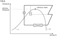
- Fig. 4 is a Mollier diagram schematically showing an aspect of change in the refrigerant in the supercritical state.
- the axis of abscissas represents enthalpy (heat quantity of the refrigerant), and the axis of ordinates represents the pressure of the refrigerant.
- a curve L1 represents a saturated liquid line
- a curve L2 represents a saturated vapor line.
- controller 100 performs control of compressor 10 and third expansion valve 40 such that the pressure of the refrigerant within load device 3 does not exceed the design pressure of load device 3.
- controller 100 performs decompression by third expansion valve 40. Specifically, controller 100 controls third expansion valve 40 as described below.
- Controller 100 feedback-controls third expansion valve 40 such that pressure P1 in pipe 83 at the outlet of third expansion valve 40 matches a target pressure. Specifically, when pressure P1 is higher than the target pressure, controller 100 decreases the degree of opening of third expansion valve 40. Thereby, the amount of decompression by third expansion valve 40 increases, and thus pressure P1 decreases. On the other hand, when pressure P1 is lower than the target pressure, controller 100 increases the degree of opening of third expansion valve 40. Thereby, the amount of decompression by third expansion valve 40 decreases, and thus pressure P1 increases. When pressure P1 is equal to the target pressure, controller 100 maintains the degree of opening of third expansion valve 40 in the present state.
- pressure P1 is controlled as described above, the pressure of the refrigerant within load device 3 can be set to be lower than or equal to a design pressure of a conventional refrigeration apparatus which uses an ordinary refrigerant whose supercritical region is not used (for example, R410A or the like), and load device 3 can be used in common with a conventional load device which uses an ordinary refrigerant.
- a design pressure of a conventional refrigeration apparatus which uses an ordinary refrigerant whose supercritical region is not used for example, R410A or the like
- discharge temperature TH of compressor 10 in the main refrigerant circuit can be controlled, subcooling in the main refrigerant circuit can be ensured, and the amount of the refrigerant in the main refrigerant circuit can be adjusted by providing injection flow path 101 branching from the main refrigerant circuit. That is, injection flow path 101 can control discharge temperature TH of compressor 10 by causing the refrigerant in pipe 81 decompressed and having two phases to flow into compressor 10. Further, subcooling of the refrigerant in the main refrigerant circuit can be ensured by using second passage H2 of heat exchanger 30 as a portion of injection flow path 101. Further, the amount of the refrigerant in the main refrigerant circuit can be adjusted by receiver 73 placed on injection flow path 101.
- Controller 100 controls second expansion valve 71 and flow rate control valve 72 to allow injection flow path 101 to exhibit the functions of controlling discharge temperature TH in the main refrigerant circuit, ensuring subcooling in the main refrigerant circuit, and adjusting the amount of the refrigerant in the main refrigerant circuit, under each operation condition.
- Controller 100 feedback-controls the degree of opening of second expansion valve 71 such that discharge temperature TH of compressor 10 matches a target temperature. Specifically, when discharge temperature TH of compressor 10 is higher than the target temperature, controller 100 increases the degree of opening of second expansion valve 71. Thereby, the refrigerant flowing into intermediate pressure port G3 via receiver 73 increases, and thus discharge temperature TH decreases.
- controller 100 decreases the degree of opening of second expansion valve 71. Thereby, the refrigerant flowing into intermediate pressure port G3 via receiver 73 decreases, and thus discharge temperature TH increases.
- controller 100 When discharge temperature TH is equal to the target temperature, controller 100 maintains the degree of opening of second expansion valve 71 in the present state.
- controller 100 controls the degree of opening of second expansion valve 71 such that discharge temperature TH of compressor 10 approaches the target temperature.
- controller 100 controls flow rate control valve 72 according to a temperature efficiency ⁇ of heat exchanger 30 in order to ensure subcooling.
- controller 100 calculates temperature efficiency ⁇ of heat exchanger 30 from a difference between refrigerant temperature T1 at the outlet of condenser 20 and outlet temperature T2 of heat exchanger 30. Then, when calculated temperature efficiency ⁇ is larger than a target value, it is considered that the amount of the refrigerant in the main refrigerant circuit is excessive, and thus controller 100 decreases the degree of opening of flow rate control valve 72. Thereby, the amount of the liquid refrigerant passing through receiver 73 decreases and the amount of the liquid refrigerant within receiver 73 increases, and thus the amount of the refrigerant circulating through the main refrigerant circuit decreases.
- controller 100 increases the degree of opening of flow rate control valve 72. Thereby, the amount of the liquid refrigerant in receiver 73 decreases, and thus the amount of the refrigerant circulating through the main refrigerant circuit increases.
- controller 100 maintains the degree of opening of flow rate control valve 72 in the present state.
- flow rate control valve 72 may be feedback-controlled such that refrigerant temperature T1 at the outlet of condenser 20 is equal to a target temperature. In this case, it is only necessary to set the target temperature of refrigerant temperature T1 to a temperature of refrigerant temperature T1 when temperature efficiency ⁇ of heat exchanger 30 is equal to the target value.
- controller 100 increases the degree of opening of flow rate control valve 72 to increase the amount of the refrigerant flowing from receiver 73 to the main refrigerant circuit, and thereby temperature efficiency ⁇ approaches the target value.
- controller 100 determines that the refrigerant in the entire refrigerant circuit is insufficient, and controls notification device 150 to notify the user of a determined result.
- the refrigerant amount adjustment and refrigerant shortage determination using temperature efficiency ⁇ as performed in the normal state have a high determination accuracy, and also have a good following property. However, under an operation condition in the supercritical state, it is not possible to define the saturation temperature and to confirm whether subcooling is ensured. Thus, it is difficult to perform refrigerant amount adjustment and refrigerant shortage determination using the same method as that for the normal state (that is, the method that uses temperature efficiency ⁇ ).
- controller 100 performs refrigerant amount adjustment and refrigerant shortage determination using a method different from that for the normal state, that is, a method that does not use temperature efficiency ⁇ . Specifically, under the operation condition in the supercritical state, controller 100 controls the degree of opening of flow rate control valve 72 using a temperature difference ⁇ T1 between outside air temperature TA detected by temperature sensor 123 and refrigerant temperature T1 at the outlet of condenser 20 detected by temperature sensor 121.
- the amount of the refrigerant can be adjusted with respect to a limit temperature of heat exchange by condenser 20 (an air heat exchanger). For example, when temperature difference ⁇ T1 is large, it is considered that the refrigerant is excessively stored in receiver 73 and the amount of the refrigerant in the main refrigerant circuit is insufficient. Thus, controller 100 increases the degree of opening of flow rate control valve 72 according to the magnitude of temperature difference ⁇ T1. Thereby, the amount of the liquid refrigerant flowing from receiver 73 to the main refrigerant circuit is increased.
- controller 100 determines whether or not the refrigerant is insufficient, based on the "degree of opening of flow rate control valve 72" which is feedback-controlled according to temperature difference ⁇ T1 as described above.
- the degree of opening of flow rate control valve 72 is increased according to the magnitude of temperature difference ⁇ T1 by the feedback control for refrigerant amount adjustment described above. Thereby, the amount of the liquid refrigerant flowing from receiver 73 to the main refrigerant circuit is increased.
- controller 100 determines that the amount of the refrigerant in the entire refrigerant circuit including the main refrigerant circuit and the injection flow path is insufficient, and controls notification device 150 to notify the user of a determined result.
- the method of determining whether the refrigerant is insufficient based on the "degree of opening of flow rate control valve 72" which is feedback-controlled according to temperature difference ⁇ T1 may have a poor following property when compared with the method that uses temperature efficiency ⁇ , switching between the determination methods as described above allows determination of whether or not the refrigerant is insufficient in the entire operation range including the normal state and the supercritical state.
- Adjustment of the amount of the sealed refrigerant when the refrigerant is sealed in the refrigerant circuit will be described below.
- adjustment is performed, for example, by providing a sight glass on pipe 83 to check if flash gas exists in the refrigerant in pipe 83.
- expansion by third expansion valve 40 within outdoor unit 2 is performed in addition to expansion by first expansion valve 50 within load device 3, to decrease the pressure within load device 3.
- expansion by third expansion valve 40 is performed, the relation between the amount of the refrigerant and subcooling in pipe 83 is not satisfied. Accordingly, the sealed amount is adjusted using the above determined result that the amount of the refrigerant is insufficient. Specifically, while it is determined that the refrigerant is insufficient, sealing of the refrigerant is continued, and when it is not determined that the refrigerant is insufficient, it is determined that the refrigerant in an appropriate amount is filled, and sealing of the refrigerant is stopped.
- sealing of the refrigerant may be performed manually by the user of outdoor unit 2 (including an operator who installs outdoor unit 2), or may be performed automatically by controller 100.
- controller 100 automatically performs initial sealing will be described below.
- controller 100 seals the refrigerant in the refrigerant circuit until discharge pressure PH of compressor 10 detected by pressure sensor 111 reaches a threshold value. Then, controller 100 activates compressor 10 and continues sealing of the refrigerant. Since discharge pressure PH of compressor 10 is not supercritical on this occasion, refrigerant shortage detection using temperature efficiency ⁇ (refrigerant shortage detection in the normal state) is performed. While it is determined by the refrigerant shortage detection using temperature efficiency ⁇ (refrigerant shortage detection in the normal state) that the refrigerant is insufficient, controller 100 continues sealing of the refrigerant.
- controller 100 determines whether or not the magnitude of a decreasing speed of discharge temperature TH of compressor 10 detected by temperature sensor 120 is greater than a reference value. Then, when the magnitude of the decreasing speed of discharge temperature TH is greater than the reference value, that is, when discharge temperature TH is decreasing rapidly, controller 100 determines that receiver 73 is in an overflow state where receiver 73 is filled with the liquid refrigerant, and controls notification device 150 to notify the user of a determined result.
- controller 100 determines whether or not a discharge degree of superheat, which is a difference between discharge temperature TH of compressor 10 and the saturation temperature at discharge pressure PH, falls within a specification range of compressor 10. When the discharge degree of superheat does not fall within the specification range of compressor 10, controller 100 stops compressor 10.
- Fig. 5 is a flowchart showing an example of a processing procedure when controller 100 performs refrigerant amount adjustment and refrigerant shortage detection.
- Controller 100 determines whether or not discharge pressure PH of compressor 10 exceeds the critical pressure (step S10).
- controller 100 controls the degree of opening of flow rate control valve 72 using temperature difference ⁇ T1 between outside air temperature TA and refrigerant temperature T1 at the outlet of condenser 20 (step S11), as described above. For example, when temperature difference ⁇ T1 is large, controller 100 increases the degree of opening of flow rate control valve 72 according to the magnitude of temperature difference ⁇ T1.
- controller 100 determines whether or not the degree of opening of flow rate control valve 72 is the upper limit degree of opening (step S12). When the degree of opening of flow rate control valve 72 is not the upper limit degree of opening (NO in step S12), controller 100 advances the processing to step S22.
- controller 100 determines whether or not the state where the degree of opening of flow rate control valve 72 is the upper limit degree of opening continues for a predetermined period of time (step S14). When the state where the degree of opening of flow rate control valve 72 is the upper limit degree of opening does not continue for the predetermined period of time (NO in step S14), controller 100 skips the subsequent processing and advances the processing to RETURN.
- controller 100 determines that the refrigerant in the entire refrigerant circuit is insufficient, and controls notification device 150 to notify the user of a determined result (step S16).
- controller 100 calculates temperature efficiency ⁇ of heat exchanger 30 from the difference between refrigerant temperature T1 at the outlet of condenser 20 and outlet temperature T2 of heat exchanger 30, and controls flow rate control valve 72 according to calculated temperature efficiency ⁇ (step S20), as described above.
- controller 100 determines whether or not calculated temperature efficiency ⁇ is less than the lower limit value (step S21). When temperature efficiency ⁇ is less than the lower limit value (YES in step S21), controller 100 determines that the refrigerant in the entire refrigerant circuit is insufficient, and controls notification device 150 to notify the user of a determined result (step S40).
- controller 100 advances the processing to step S22.
- controller 100 determines whether or not the degree of opening of flow rate control valve 72 is the lower limit degree of opening. When the degree of opening of flow rate control valve 72 is not the lower limit degree of opening (NO in step S22), controller 100 skips the subsequent processing and advances the processing to RETURN.
- controller 100 determines whether or not discharge pressure PH of compressor 10 is greater than a threshold value, even after the state where the degree of opening of flow rate control valve 72 is the lower limit degree of opening continues for a predetermined period of time (step S24).
- the "threshold value" used in step S24 is set, for example, to a value lower than the critical pressure.
- controller 100 determines that the refrigerant circuit is in the overfilled state, and controls notification device 150 to notify the user of a determined result (step S26).
- controller 100 determines whether or not discharge temperature TH of compressor 10 is decreasing rapidly, specifically, whether or not the magnitude of the decreasing speed of discharge temperature TH of compressor 10 is greater than the reference value (step S28). Then, when the magnitude of the decreasing speed of discharge temperature TH is greater than the reference value, that is, when discharge temperature TH is decreasing rapidly, controller 100 determines that receiver 73 is in the overflow state where receiver 73 is filled with the liquid refrigerant, and controls notification device 150 to notify the user of a determined result (step S30).
- controller 100 determines whether or not the discharge degree of superheat, which is the difference between discharge temperature TH of compressor 10 and the saturation temperature at discharge pressure PH of compressor 10, falls within the specification range of compressor 10 (step S32).
- controller 100 skips the subsequent processing and advances the processing to RETURN.
- controller 100 stops compressor 10 (step S34).
- controller 100 determines whether or not the refrigerant is insufficient, using temperature efficiency ⁇ of heat exchanger 30.
- controller 100 determines whether or not the refrigerant is insufficient, using the "degree of opening of flow rate control valve 72" which is feedback-controlled according to temperature difference ⁇ T1 between outside air temperature TA and refrigerant temperature T1 at the outlet of condenser 20, instead of using temperature efficiency ⁇ of heat exchanger 30. Switching between the methods for determining whether the refrigerant is insufficient as described above allows appropriate determination of whether or not the refrigerant is insufficient in the refrigerant circuit, even under the operation condition in the supercritical state. As a result, in refrigeration cycle apparatus 1 using the refrigerant that can reach the supercritical state, it is possible to determine whether or not the refrigerant is insufficient in the entire operation range including the normal state and the supercritical state.
- refrigeration cycle apparatus 1 may be utilized in an air conditioner or the like.
- 1 refrigeration cycle apparatus; 2: outdoor unit; 3: load device; 10: compressor; 20: condenser; 22: fan; 30: heat exchanger; 40: third expansion valve; 50: first expansion valve; 60: evaporator; 71: second expansion valve; 72: flow rate control valve; 73: receiver; 75: on-off valve; 80, 81 to 83, 85, 89, 91 to 94, 96: pipe; 84, 88: extension pipe; 95: degassing passage; 100: controller; 101: injection flow path; 102: CPU; 104: memory; 110 to 113: pressure sensor; 120 to 125: temperature sensor; 150: notification device; G1: suction port; G2: discharge port; G3: intermediate pressure port; H1: first passage.
Landscapes
- Engineering & Computer Science (AREA)
- Physics & Mathematics (AREA)
- Mechanical Engineering (AREA)
- Thermal Sciences (AREA)
- General Engineering & Computer Science (AREA)
- Air Conditioning Control Device (AREA)
Applications Claiming Priority (1)
| Application Number | Priority Date | Filing Date | Title |
|---|---|---|---|
| PCT/JP2020/014278 WO2021192292A1 (ja) | 2020-03-27 | 2020-03-27 | 室外ユニットおよび冷凍サイクル装置 |
Publications (3)
| Publication Number | Publication Date |
|---|---|
| EP4130615A1 EP4130615A1 (en) | 2023-02-08 |
| EP4130615A4 EP4130615A4 (en) | 2023-04-26 |
| EP4130615B1 true EP4130615B1 (en) | 2025-05-14 |
Family
ID=77889972
Family Applications (1)
| Application Number | Title | Priority Date | Filing Date |
|---|---|---|---|
| EP20927414.1A Active EP4130615B1 (en) | 2020-03-27 | 2020-03-27 | Outdoor unit and refrigeration cycle device |
Country Status (3)
| Country | Link |
|---|---|
| EP (1) | EP4130615B1 (https=) |
| JP (1) | JP7282258B2 (https=) |
| WO (1) | WO2021192292A1 (https=) |
Families Citing this family (3)
| Publication number | Priority date | Publication date | Assignee | Title |
|---|---|---|---|---|
| JP7751466B2 (ja) * | 2021-11-22 | 2025-10-08 | 日本キヤリア株式会社 | 冷凍装置 |
| WO2025069175A1 (ja) * | 2023-09-26 | 2025-04-03 | 三菱電機株式会社 | 冷凍サイクル装置 |
| KR20250123583A (ko) * | 2024-02-08 | 2025-08-18 | 엘지전자 주식회사 | 냉장고 및 이의 제어 방법 |
Family Cites Families (9)
| Publication number | Priority date | Publication date | Assignee | Title |
|---|---|---|---|---|
| JP2007263390A (ja) * | 2006-03-27 | 2007-10-11 | Sanyo Electric Co Ltd | 冷凍サイクル装置 |
| JP4862198B2 (ja) * | 2006-04-11 | 2012-01-25 | 株式会社前川製作所 | Co2冷媒を用いた給湯装置及びその運転方法 |
| JP4687710B2 (ja) | 2007-12-27 | 2011-05-25 | 三菱電機株式会社 | 冷凍装置 |
| JP2010127531A (ja) | 2008-11-27 | 2010-06-10 | Mitsubishi Electric Corp | 冷凍空調装置 |
| US8966916B2 (en) * | 2011-03-10 | 2015-03-03 | Streamline Automation, Llc | Extended range heat pump |
| JP6080031B2 (ja) * | 2012-02-15 | 2017-02-15 | パナソニックIpマネジメント株式会社 | 冷凍装置 |
| JP2014119221A (ja) | 2012-12-18 | 2014-06-30 | Daikin Ind Ltd | 冷凍装置 |
| JP2015049024A (ja) * | 2013-09-04 | 2015-03-16 | パナソニック株式会社 | 冷凍装置及び冷凍装置の冷媒量調整方法 |
| CN105683681A (zh) * | 2013-10-28 | 2016-06-15 | 三菱电机株式会社 | 制冷循环装置 |
-
2020
- 2020-03-27 JP JP2022510390A patent/JP7282258B2/ja active Active
- 2020-03-27 WO PCT/JP2020/014278 patent/WO2021192292A1/ja not_active Ceased
- 2020-03-27 EP EP20927414.1A patent/EP4130615B1/en active Active
Also Published As
| Publication number | Publication date |
|---|---|
| JP7282258B2 (ja) | 2023-05-26 |
| EP4130615A1 (en) | 2023-02-08 |
| EP4130615A4 (en) | 2023-04-26 |
| JPWO2021192292A1 (https=) | 2021-09-30 |
| WO2021192292A1 (ja) | 2021-09-30 |
Similar Documents
| Publication | Publication Date | Title |
|---|---|---|
| US11609031B2 (en) | Refrigeration cycle apparatus | |
| EP3147587B1 (en) | Air conditioning device | |
| EP3954947B1 (en) | Outdoor unit, refrigeration cycle device, and refrigerating machine | |
| US11959672B2 (en) | Air-conditioning apparatus | |
| EP4130615B1 (en) | Outdoor unit and refrigeration cycle device | |
| WO2010013392A1 (ja) | 冷凍装置 | |
| US20170370608A1 (en) | Air-conditioning apparatus | |
| US12038213B2 (en) | Refrigeration cycle apparatus | |
| US20230258377A1 (en) | Refrigeration system and the control method thereof | |
| EP4030116B1 (en) | Outdoor unit and refrigeration cycle device | |
| EP4030117B1 (en) | Outdoor unit and refrigeration cycle device | |
| GB2602893A (en) | Outdoor unit and refrigeration cycle device | |
| US12215905B2 (en) | Air conditioning apparatus | |
| EP4015939B1 (en) | Refrigeration device | |
| EP4030115B1 (en) | Outdoor unit and refrigeration cycle device | |
| EP3306238B1 (en) | Control device, refrigerant circuit system and control method | |
| EP4030122B1 (en) | Outdoor unit and refrigeration cycle apparatus | |
| KR20150051982A (ko) | 공기조화기 및 그 제어방법 | |
| EP4089349B1 (en) | Air conditioner and control method thereof | |
| JP7342269B2 (ja) | 冷熱源ユニット、および冷凍サイクル装置 | |
| JP7150191B2 (ja) | 室外ユニットおよび冷凍サイクル装置 | |
| AU1550301A (en) | Refrigerating device | |
| US20240151443A1 (en) | Refrigeration cycle apparatus, control method for refrigeration cycle apparatus, and non-transitory computer-readable recording medium |
Legal Events
| Date | Code | Title | Description |
|---|---|---|---|
| STAA | Information on the status of an ep patent application or granted ep patent |
Free format text: STATUS: THE INTERNATIONAL PUBLICATION HAS BEEN MADE |
|
| PUAI | Public reference made under article 153(3) epc to a published international application that has entered the european phase |
Free format text: ORIGINAL CODE: 0009012 |
|
| STAA | Information on the status of an ep patent application or granted ep patent |
Free format text: STATUS: REQUEST FOR EXAMINATION WAS MADE |
|
| 17P | Request for examination filed |
Effective date: 20220819 |
|
| AK | Designated contracting states |
Kind code of ref document: A1 Designated state(s): AL AT BE BG CH CY CZ DE DK EE ES FI FR GB GR HR HU IE IS IT LI LT LU LV MC MK MT NL NO PL PT RO RS SE SI SK SM TR |
|
| A4 | Supplementary search report drawn up and despatched |
Effective date: 20230328 |
|
| RIC1 | Information provided on ipc code assigned before grant |
Ipc: F25B 45/00 20060101ALI20230322BHEP Ipc: F25B 1/00 20060101ALI20230322BHEP Ipc: F25B 49/02 20060101AFI20230322BHEP |
|
| DAV | Request for validation of the european patent (deleted) | ||
| DAX | Request for extension of the european patent (deleted) | ||
| GRAP | Despatch of communication of intention to grant a patent |
Free format text: ORIGINAL CODE: EPIDOSNIGR1 |
|
| STAA | Information on the status of an ep patent application or granted ep patent |
Free format text: STATUS: GRANT OF PATENT IS INTENDED |
|
| INTG | Intention to grant announced |
Effective date: 20250128 |
|
| GRAS | Grant fee paid |
Free format text: ORIGINAL CODE: EPIDOSNIGR3 |
|
| GRAA | (expected) grant |
Free format text: ORIGINAL CODE: 0009210 |
|
| STAA | Information on the status of an ep patent application or granted ep patent |
Free format text: STATUS: THE PATENT HAS BEEN GRANTED |
|
| AK | Designated contracting states |
Kind code of ref document: B1 Designated state(s): AL AT BE BG CH CY CZ DE DK EE ES FI FR GB GR HR HU IE IS IT LI LT LU LV MC MK MT NL NO PL PT RO RS SE SI SK SM TR |
|
| REG | Reference to a national code |
Ref country code: GB Ref legal event code: FG4D |
|
| REG | Reference to a national code |
Ref country code: CH Ref legal event code: EP |
|
| REG | Reference to a national code |
Ref country code: IE Ref legal event code: FG4D |
|
| REG | Reference to a national code |
Ref country code: DE Ref legal event code: R096 Ref document number: 602020051447 Country of ref document: DE |
|
| REG | Reference to a national code |
Ref country code: NL Ref legal event code: MP Effective date: 20250514 |
|
| PG25 | Lapsed in a contracting state [announced via postgrant information from national office to epo] |
Ref country code: PT Free format text: LAPSE BECAUSE OF FAILURE TO SUBMIT A TRANSLATION OF THE DESCRIPTION OR TO PAY THE FEE WITHIN THE PRESCRIBED TIME-LIMIT Effective date: 20250915 Ref country code: FI Free format text: LAPSE BECAUSE OF FAILURE TO SUBMIT A TRANSLATION OF THE DESCRIPTION OR TO PAY THE FEE WITHIN THE PRESCRIBED TIME-LIMIT Effective date: 20250514 Ref country code: ES Free format text: LAPSE BECAUSE OF FAILURE TO SUBMIT A TRANSLATION OF THE DESCRIPTION OR TO PAY THE FEE WITHIN THE PRESCRIBED TIME-LIMIT Effective date: 20250514 |
|
| REG | Reference to a national code |
Ref country code: LT Ref legal event code: MG9D |
|
| PG25 | Lapsed in a contracting state [announced via postgrant information from national office to epo] |
Ref country code: NO Free format text: LAPSE BECAUSE OF FAILURE TO SUBMIT A TRANSLATION OF THE DESCRIPTION OR TO PAY THE FEE WITHIN THE PRESCRIBED TIME-LIMIT Effective date: 20250814 Ref country code: GR Free format text: LAPSE BECAUSE OF FAILURE TO SUBMIT A TRANSLATION OF THE DESCRIPTION OR TO PAY THE FEE WITHIN THE PRESCRIBED TIME-LIMIT Effective date: 20250815 |
|
| PG25 | Lapsed in a contracting state [announced via postgrant information from national office to epo] |
Ref country code: NL Free format text: LAPSE BECAUSE OF FAILURE TO SUBMIT A TRANSLATION OF THE DESCRIPTION OR TO PAY THE FEE WITHIN THE PRESCRIBED TIME-LIMIT Effective date: 20250514 Ref country code: PL Free format text: LAPSE BECAUSE OF FAILURE TO SUBMIT A TRANSLATION OF THE DESCRIPTION OR TO PAY THE FEE WITHIN THE PRESCRIBED TIME-LIMIT Effective date: 20250514 |
|
| REG | Reference to a national code |
Ref country code: AT Ref legal event code: MK05 Ref document number: 1795071 Country of ref document: AT Kind code of ref document: T Effective date: 20250514 |
|
| PG25 | Lapsed in a contracting state [announced via postgrant information from national office to epo] |
Ref country code: BG Free format text: LAPSE BECAUSE OF FAILURE TO SUBMIT A TRANSLATION OF THE DESCRIPTION OR TO PAY THE FEE WITHIN THE PRESCRIBED TIME-LIMIT Effective date: 20250514 |
|
| PG25 | Lapsed in a contracting state [announced via postgrant information from national office to epo] |
Ref country code: HR Free format text: LAPSE BECAUSE OF FAILURE TO SUBMIT A TRANSLATION OF THE DESCRIPTION OR TO PAY THE FEE WITHIN THE PRESCRIBED TIME-LIMIT Effective date: 20250514 |
|
| PG25 | Lapsed in a contracting state [announced via postgrant information from national office to epo] |
Ref country code: AT Free format text: LAPSE BECAUSE OF FAILURE TO SUBMIT A TRANSLATION OF THE DESCRIPTION OR TO PAY THE FEE WITHIN THE PRESCRIBED TIME-LIMIT Effective date: 20250514 |
|
| PG25 | Lapsed in a contracting state [announced via postgrant information from national office to epo] |
Ref country code: RS Free format text: LAPSE BECAUSE OF FAILURE TO SUBMIT A TRANSLATION OF THE DESCRIPTION OR TO PAY THE FEE WITHIN THE PRESCRIBED TIME-LIMIT Effective date: 20250814 |
|
| PG25 | Lapsed in a contracting state [announced via postgrant information from national office to epo] |
Ref country code: IS Free format text: LAPSE BECAUSE OF FAILURE TO SUBMIT A TRANSLATION OF THE DESCRIPTION OR TO PAY THE FEE WITHIN THE PRESCRIBED TIME-LIMIT Effective date: 20250914 |
|
| PG25 | Lapsed in a contracting state [announced via postgrant information from national office to epo] |
Ref country code: LV Free format text: LAPSE BECAUSE OF FAILURE TO SUBMIT A TRANSLATION OF THE DESCRIPTION OR TO PAY THE FEE WITHIN THE PRESCRIBED TIME-LIMIT Effective date: 20250514 |
|
| PG25 | Lapsed in a contracting state [announced via postgrant information from national office to epo] |
Ref country code: SM Free format text: LAPSE BECAUSE OF FAILURE TO SUBMIT A TRANSLATION OF THE DESCRIPTION OR TO PAY THE FEE WITHIN THE PRESCRIBED TIME-LIMIT Effective date: 20250514 Ref country code: DK Free format text: LAPSE BECAUSE OF FAILURE TO SUBMIT A TRANSLATION OF THE DESCRIPTION OR TO PAY THE FEE WITHIN THE PRESCRIBED TIME-LIMIT Effective date: 20250514 |
|
| PG25 | Lapsed in a contracting state [announced via postgrant information from national office to epo] |
Ref country code: CZ Free format text: LAPSE BECAUSE OF FAILURE TO SUBMIT A TRANSLATION OF THE DESCRIPTION OR TO PAY THE FEE WITHIN THE PRESCRIBED TIME-LIMIT Effective date: 20250514 |
|
| PG25 | Lapsed in a contracting state [announced via postgrant information from national office to epo] |
Ref country code: EE Free format text: LAPSE BECAUSE OF FAILURE TO SUBMIT A TRANSLATION OF THE DESCRIPTION OR TO PAY THE FEE WITHIN THE PRESCRIBED TIME-LIMIT Effective date: 20250514 |
|
| PG25 | Lapsed in a contracting state [announced via postgrant information from national office to epo] |
Ref country code: SK Free format text: LAPSE BECAUSE OF FAILURE TO SUBMIT A TRANSLATION OF THE DESCRIPTION OR TO PAY THE FEE WITHIN THE PRESCRIBED TIME-LIMIT Effective date: 20250514 |
|
| PG25 | Lapsed in a contracting state [announced via postgrant information from national office to epo] |
Ref country code: IT Free format text: LAPSE BECAUSE OF FAILURE TO SUBMIT A TRANSLATION OF THE DESCRIPTION OR TO PAY THE FEE WITHIN THE PRESCRIBED TIME-LIMIT Effective date: 20250514 |
|
| REG | Reference to a national code |
Ref country code: DE Ref legal event code: R097 Ref document number: 602020051447 Country of ref document: DE |
|
| PLBE | No opposition filed within time limit |
Free format text: ORIGINAL CODE: 0009261 |
|
| STAA | Information on the status of an ep patent application or granted ep patent |
Free format text: STATUS: NO OPPOSITION FILED WITHIN TIME LIMIT |
|
| REG | Reference to a national code |
Ref country code: CH Ref legal event code: L10 Free format text: ST27 STATUS EVENT CODE: U-0-0-L10-L00 (AS PROVIDED BY THE NATIONAL OFFICE) Effective date: 20260325 |
|
| PGFP | Annual fee paid to national office [announced via postgrant information from national office to epo] |
Ref country code: GB Payment date: 20260209 Year of fee payment: 7 |
|
| 26N | No opposition filed |
Effective date: 20260217 |