EP4130519A1 - Tank - Google Patents
Tank Download PDFInfo
- Publication number
- EP4130519A1 EP4130519A1 EP21774637.9A EP21774637A EP4130519A1 EP 4130519 A1 EP4130519 A1 EP 4130519A1 EP 21774637 A EP21774637 A EP 21774637A EP 4130519 A1 EP4130519 A1 EP 4130519A1
- Authority
- EP
- European Patent Office
- Prior art keywords
- resin
- fiber bundles
- impregnated fiber
- liner
- gaps
- Prior art date
- Legal status (The legal status is an assumption and is not a legal conclusion. Google has not performed a legal analysis and makes no representation as to the accuracy of the status listed.)
- Pending
Links
- 239000000835 fiber Substances 0.000 claims abstract description 187
- 239000011347 resin Substances 0.000 claims abstract description 60
- 229920005989 resin Polymers 0.000 claims abstract description 60
- 230000003014 reinforcing effect Effects 0.000 claims abstract description 33
- 238000004804 winding Methods 0.000 claims abstract description 20
- 238000004519 manufacturing process Methods 0.000 abstract description 4
- 238000000034 method Methods 0.000 description 45
- 238000000465 moulding Methods 0.000 description 32
- 238000009730 filament winding Methods 0.000 description 13
- 229920000049 Carbon (fiber) Polymers 0.000 description 12
- 239000004917 carbon fiber Substances 0.000 description 12
- 238000005259 measurement Methods 0.000 description 11
- 239000011342 resin composition Substances 0.000 description 11
- 238000010586 diagram Methods 0.000 description 10
- 230000007423 decrease Effects 0.000 description 9
- 238000005470 impregnation Methods 0.000 description 9
- 230000009172 bursting Effects 0.000 description 8
- 238000004364 calculation method Methods 0.000 description 7
- 239000007789 gas Substances 0.000 description 7
- XAGFODPZIPBFFR-UHFFFAOYSA-N aluminium Chemical compound [Al] XAGFODPZIPBFFR-UHFFFAOYSA-N 0.000 description 5
- 229910052782 aluminium Inorganic materials 0.000 description 5
- 230000015572 biosynthetic process Effects 0.000 description 5
- 238000012360 testing method Methods 0.000 description 5
- 230000007547 defect Effects 0.000 description 4
- VNWKTOKETHGBQD-UHFFFAOYSA-N methane Chemical compound C VNWKTOKETHGBQD-UHFFFAOYSA-N 0.000 description 4
- 229920002430 Fibre-reinforced plastic Polymers 0.000 description 3
- 230000000052 comparative effect Effects 0.000 description 3
- 239000003822 epoxy resin Substances 0.000 description 3
- 239000011151 fibre-reinforced plastic Substances 0.000 description 3
- 238000002156 mixing Methods 0.000 description 3
- 229920000647 polyepoxide Polymers 0.000 description 3
- 238000003756 stirring Methods 0.000 description 3
- 239000000126 substance Substances 0.000 description 3
- XKRFYHLGVUSROY-UHFFFAOYSA-N Argon Chemical compound [Ar] XKRFYHLGVUSROY-UHFFFAOYSA-N 0.000 description 2
- IJGRMHOSHXDMSA-UHFFFAOYSA-N Atomic nitrogen Chemical compound N#N IJGRMHOSHXDMSA-UHFFFAOYSA-N 0.000 description 2
- UFHFLCQGNIYNRP-UHFFFAOYSA-N Hydrogen Chemical compound [H][H] UFHFLCQGNIYNRP-UHFFFAOYSA-N 0.000 description 2
- XEEYBQQBJWHFJM-UHFFFAOYSA-N Iron Chemical compound [Fe] XEEYBQQBJWHFJM-UHFFFAOYSA-N 0.000 description 2
- -1 aromatic urea compound Chemical class 0.000 description 2
- 239000004202 carbamide Substances 0.000 description 2
- 230000001419 dependent effect Effects 0.000 description 2
- QGBSISYHAICWAH-UHFFFAOYSA-N dicyandiamide Chemical compound NC(N)=NC#N QGBSISYHAICWAH-UHFFFAOYSA-N 0.000 description 2
- 230000000694 effects Effects 0.000 description 2
- 239000007769 metal material Substances 0.000 description 2
- 239000000203 mixture Substances 0.000 description 2
- 239000004848 polyfunctional curative Substances 0.000 description 2
- 238000010526 radical polymerization reaction Methods 0.000 description 2
- 239000012783 reinforcing fiber Substances 0.000 description 2
- XBTRYWRVOBZSGM-UHFFFAOYSA-N (4-methylphenyl)methanediamine Chemical compound CC1=CC=C(C(N)N)C=C1 XBTRYWRVOBZSGM-UHFFFAOYSA-N 0.000 description 1
- XMTQQYYKAHVGBJ-UHFFFAOYSA-N 3-(3,4-DICHLOROPHENYL)-1,1-DIMETHYLUREA Chemical compound CN(C)C(=O)NC1=CC=C(Cl)C(Cl)=C1 XMTQQYYKAHVGBJ-UHFFFAOYSA-N 0.000 description 1
- 238000012935 Averaging Methods 0.000 description 1
- ZOXJGFHDIHLPTG-UHFFFAOYSA-N Boron Chemical compound [B] ZOXJGFHDIHLPTG-UHFFFAOYSA-N 0.000 description 1
- OKTJSMMVPCPJKN-UHFFFAOYSA-N Carbon Chemical compound [C] OKTJSMMVPCPJKN-UHFFFAOYSA-N 0.000 description 1
- PMMYEEVYMWASQN-DMTCNVIQSA-N Hydroxyproline Chemical compound O[C@H]1CN[C@H](C(O)=O)C1 PMMYEEVYMWASQN-DMTCNVIQSA-N 0.000 description 1
- 229910000831 Steel Inorganic materials 0.000 description 1
- 239000004809 Teflon Substances 0.000 description 1
- 229920006362 Teflon® Polymers 0.000 description 1
- NIXOWILDQLNWCW-UHFFFAOYSA-N acrylic acid group Chemical group C(C=C)(=O)O NIXOWILDQLNWCW-UHFFFAOYSA-N 0.000 description 1
- 229920000800 acrylic rubber Polymers 0.000 description 1
- PNEYBMLMFCGWSK-UHFFFAOYSA-N aluminium oxide Inorganic materials [O-2].[O-2].[O-2].[Al+3].[Al+3] PNEYBMLMFCGWSK-UHFFFAOYSA-N 0.000 description 1
- 239000004760 aramid Substances 0.000 description 1
- 229920006231 aramid fiber Polymers 0.000 description 1
- 229910052786 argon Inorganic materials 0.000 description 1
- QVGXLLKOCUKJST-UHFFFAOYSA-N atomic oxygen Chemical compound [O] QVGXLLKOCUKJST-UHFFFAOYSA-N 0.000 description 1
- 238000007664 blowing Methods 0.000 description 1
- 229910052796 boron Inorganic materials 0.000 description 1
- 239000003054 catalyst Substances 0.000 description 1
- 239000002131 composite material Substances 0.000 description 1
- 230000003247 decreasing effect Effects 0.000 description 1
- 238000013461 design Methods 0.000 description 1
- 238000001514 detection method Methods 0.000 description 1
- 230000007613 environmental effect Effects 0.000 description 1
- 239000002360 explosive Substances 0.000 description 1
- 239000003365 glass fiber Substances 0.000 description 1
- 239000010439 graphite Substances 0.000 description 1
- 229910002804 graphite Inorganic materials 0.000 description 1
- 239000001257 hydrogen Substances 0.000 description 1
- 229910052739 hydrogen Inorganic materials 0.000 description 1
- 229910052742 iron Inorganic materials 0.000 description 1
- 239000003915 liquefied petroleum gas Substances 0.000 description 1
- 239000007788 liquid Substances 0.000 description 1
- 239000000463 material Substances 0.000 description 1
- 239000011159 matrix material Substances 0.000 description 1
- 239000003345 natural gas Substances 0.000 description 1
- 229910052757 nitrogen Inorganic materials 0.000 description 1
- 239000001301 oxygen Substances 0.000 description 1
- 229910052760 oxygen Inorganic materials 0.000 description 1
- 230000000737 periodic effect Effects 0.000 description 1
- 230000035699 permeability Effects 0.000 description 1
- 229920000058 polyacrylate Polymers 0.000 description 1
- 230000000717 retained effect Effects 0.000 description 1
- 238000000926 separation method Methods 0.000 description 1
- HBMJWWWQQXIZIP-UHFFFAOYSA-N silicon carbide Chemical compound [Si+]#[C-] HBMJWWWQQXIZIP-UHFFFAOYSA-N 0.000 description 1
- 229910010271 silicon carbide Inorganic materials 0.000 description 1
- 125000006850 spacer group Chemical group 0.000 description 1
- 239000010959 steel Substances 0.000 description 1
- 229920001187 thermosetting polymer Polymers 0.000 description 1
- 238000009966 trimming Methods 0.000 description 1
- 230000000007 visual effect Effects 0.000 description 1
- XLYOFNOQVPJJNP-UHFFFAOYSA-N water Substances O XLYOFNOQVPJJNP-UHFFFAOYSA-N 0.000 description 1
Images




Classifications
-
- F—MECHANICAL ENGINEERING; LIGHTING; HEATING; WEAPONS; BLASTING
- F17—STORING OR DISTRIBUTING GASES OR LIQUIDS
- F17C—VESSELS FOR CONTAINING OR STORING COMPRESSED, LIQUEFIED OR SOLIDIFIED GASES; FIXED-CAPACITY GAS-HOLDERS; FILLING VESSELS WITH, OR DISCHARGING FROM VESSELS, COMPRESSED, LIQUEFIED, OR SOLIDIFIED GASES
- F17C1/00—Pressure vessels, e.g. gas cylinder, gas tank, replaceable cartridge
- F17C1/02—Pressure vessels, e.g. gas cylinder, gas tank, replaceable cartridge involving reinforcing arrangements
- F17C1/04—Protecting sheathings
- F17C1/06—Protecting sheathings built-up from wound-on bands or filamentary material, e.g. wires
-
- B—PERFORMING OPERATIONS; TRANSPORTING
- B29—WORKING OF PLASTICS; WORKING OF SUBSTANCES IN A PLASTIC STATE IN GENERAL
- B29C—SHAPING OR JOINING OF PLASTICS; SHAPING OF MATERIAL IN A PLASTIC STATE, NOT OTHERWISE PROVIDED FOR; AFTER-TREATMENT OF THE SHAPED PRODUCTS, e.g. REPAIRING
- B29C53/00—Shaping by bending, folding, twisting, straightening or flattening; Apparatus therefor
- B29C53/56—Winding and joining, e.g. winding spirally
- B29C53/58—Winding and joining, e.g. winding spirally helically
- B29C53/60—Winding and joining, e.g. winding spirally helically using internal forming surfaces, e.g. mandrels
- B29C53/602—Winding and joining, e.g. winding spirally helically using internal forming surfaces, e.g. mandrels for tubular articles having closed or nearly closed ends, e.g. vessels, tanks, containers
-
- B—PERFORMING OPERATIONS; TRANSPORTING
- B29—WORKING OF PLASTICS; WORKING OF SUBSTANCES IN A PLASTIC STATE IN GENERAL
- B29C—SHAPING OR JOINING OF PLASTICS; SHAPING OF MATERIAL IN A PLASTIC STATE, NOT OTHERWISE PROVIDED FOR; AFTER-TREATMENT OF THE SHAPED PRODUCTS, e.g. REPAIRING
- B29C63/00—Lining or sheathing, i.e. applying preformed layers or sheathings of plastics; Apparatus therefor
- B29C63/02—Lining or sheathing, i.e. applying preformed layers or sheathings of plastics; Apparatus therefor using sheet or web-like material
- B29C63/04—Lining or sheathing, i.e. applying preformed layers or sheathings of plastics; Apparatus therefor using sheet or web-like material by folding, winding, bending or the like
- B29C63/06—Lining or sheathing, i.e. applying preformed layers or sheathings of plastics; Apparatus therefor using sheet or web-like material by folding, winding, bending or the like around tubular articles
-
- B—PERFORMING OPERATIONS; TRANSPORTING
- B29—WORKING OF PLASTICS; WORKING OF SUBSTANCES IN A PLASTIC STATE IN GENERAL
- B29C—SHAPING OR JOINING OF PLASTICS; SHAPING OF MATERIAL IN A PLASTIC STATE, NOT OTHERWISE PROVIDED FOR; AFTER-TREATMENT OF THE SHAPED PRODUCTS, e.g. REPAIRING
- B29C63/00—Lining or sheathing, i.e. applying preformed layers or sheathings of plastics; Apparatus therefor
- B29C63/02—Lining or sheathing, i.e. applying preformed layers or sheathings of plastics; Apparatus therefor using sheet or web-like material
- B29C63/04—Lining or sheathing, i.e. applying preformed layers or sheathings of plastics; Apparatus therefor using sheet or web-like material by folding, winding, bending or the like
- B29C63/08—Lining or sheathing, i.e. applying preformed layers or sheathings of plastics; Apparatus therefor using sheet or web-like material by folding, winding, bending or the like by winding helically
- B29C63/10—Lining or sheathing, i.e. applying preformed layers or sheathings of plastics; Apparatus therefor using sheet or web-like material by folding, winding, bending or the like by winding helically around tubular articles
-
- B—PERFORMING OPERATIONS; TRANSPORTING
- B29—WORKING OF PLASTICS; WORKING OF SUBSTANCES IN A PLASTIC STATE IN GENERAL
- B29C—SHAPING OR JOINING OF PLASTICS; SHAPING OF MATERIAL IN A PLASTIC STATE, NOT OTHERWISE PROVIDED FOR; AFTER-TREATMENT OF THE SHAPED PRODUCTS, e.g. REPAIRING
- B29C70/00—Shaping composites, i.e. plastics material comprising reinforcements, fillers or preformed parts, e.g. inserts
- B29C70/003—Shaping composites, i.e. plastics material comprising reinforcements, fillers or preformed parts, e.g. inserts characterised by the matrix material, e.g. material composition or physical properties
-
- B—PERFORMING OPERATIONS; TRANSPORTING
- B29—WORKING OF PLASTICS; WORKING OF SUBSTANCES IN A PLASTIC STATE IN GENERAL
- B29C—SHAPING OR JOINING OF PLASTICS; SHAPING OF MATERIAL IN A PLASTIC STATE, NOT OTHERWISE PROVIDED FOR; AFTER-TREATMENT OF THE SHAPED PRODUCTS, e.g. REPAIRING
- B29C70/00—Shaping composites, i.e. plastics material comprising reinforcements, fillers or preformed parts, e.g. inserts
- B29C70/04—Shaping composites, i.e. plastics material comprising reinforcements, fillers or preformed parts, e.g. inserts comprising reinforcements only, e.g. self-reinforcing plastics
- B29C70/06—Fibrous reinforcements only
- B29C70/08—Fibrous reinforcements only comprising combinations of different forms of fibrous reinforcements incorporated in matrix material, forming one or more layers, and with or without non-reinforced layers
- B29C70/088—Fibrous reinforcements only comprising combinations of different forms of fibrous reinforcements incorporated in matrix material, forming one or more layers, and with or without non-reinforced layers and with one or more layers of non-plastics material or non-specified material, e.g. supports
-
- B—PERFORMING OPERATIONS; TRANSPORTING
- B29—WORKING OF PLASTICS; WORKING OF SUBSTANCES IN A PLASTIC STATE IN GENERAL
- B29C—SHAPING OR JOINING OF PLASTICS; SHAPING OF MATERIAL IN A PLASTIC STATE, NOT OTHERWISE PROVIDED FOR; AFTER-TREATMENT OF THE SHAPED PRODUCTS, e.g. REPAIRING
- B29C70/00—Shaping composites, i.e. plastics material comprising reinforcements, fillers or preformed parts, e.g. inserts
- B29C70/04—Shaping composites, i.e. plastics material comprising reinforcements, fillers or preformed parts, e.g. inserts comprising reinforcements only, e.g. self-reinforcing plastics
- B29C70/06—Fibrous reinforcements only
- B29C70/10—Fibrous reinforcements only characterised by the structure of fibrous reinforcements, e.g. hollow fibres
- B29C70/16—Fibrous reinforcements only characterised by the structure of fibrous reinforcements, e.g. hollow fibres using fibres of substantial or continuous length
-
- B—PERFORMING OPERATIONS; TRANSPORTING
- B29—WORKING OF PLASTICS; WORKING OF SUBSTANCES IN A PLASTIC STATE IN GENERAL
- B29C—SHAPING OR JOINING OF PLASTICS; SHAPING OF MATERIAL IN A PLASTIC STATE, NOT OTHERWISE PROVIDED FOR; AFTER-TREATMENT OF THE SHAPED PRODUCTS, e.g. REPAIRING
- B29C70/00—Shaping composites, i.e. plastics material comprising reinforcements, fillers or preformed parts, e.g. inserts
- B29C70/04—Shaping composites, i.e. plastics material comprising reinforcements, fillers or preformed parts, e.g. inserts comprising reinforcements only, e.g. self-reinforcing plastics
- B29C70/28—Shaping operations therefor
- B29C70/30—Shaping by lay-up, i.e. applying fibres, tape or broadsheet on a mould, former or core; Shaping by spray-up, i.e. spraying of fibres on a mould, former or core
- B29C70/32—Shaping by lay-up, i.e. applying fibres, tape or broadsheet on a mould, former or core; Shaping by spray-up, i.e. spraying of fibres on a mould, former or core on a rotating mould, former or core
-
- F—MECHANICAL ENGINEERING; LIGHTING; HEATING; WEAPONS; BLASTING
- F16—ENGINEERING ELEMENTS AND UNITS; GENERAL MEASURES FOR PRODUCING AND MAINTAINING EFFECTIVE FUNCTIONING OF MACHINES OR INSTALLATIONS; THERMAL INSULATION IN GENERAL
- F16J—PISTONS; CYLINDERS; SEALINGS
- F16J12/00—Pressure vessels in general
-
- B—PERFORMING OPERATIONS; TRANSPORTING
- B29—WORKING OF PLASTICS; WORKING OF SUBSTANCES IN A PLASTIC STATE IN GENERAL
- B29L—INDEXING SCHEME ASSOCIATED WITH SUBCLASS B29C, RELATING TO PARTICULAR ARTICLES
- B29L2031/00—Other particular articles
- B29L2031/712—Containers; Packaging elements or accessories, Packages
- B29L2031/7154—Barrels, drums, tuns, vats
- B29L2031/7156—Pressure vessels
-
- F—MECHANICAL ENGINEERING; LIGHTING; HEATING; WEAPONS; BLASTING
- F17—STORING OR DISTRIBUTING GASES OR LIQUIDS
- F17C—VESSELS FOR CONTAINING OR STORING COMPRESSED, LIQUEFIED OR SOLIDIFIED GASES; FIXED-CAPACITY GAS-HOLDERS; FILLING VESSELS WITH, OR DISCHARGING FROM VESSELS, COMPRESSED, LIQUEFIED, OR SOLIDIFIED GASES
- F17C1/00—Pressure vessels, e.g. gas cylinder, gas tank, replaceable cartridge
- F17C1/16—Pressure vessels, e.g. gas cylinder, gas tank, replaceable cartridge constructed of plastics materials
-
- F—MECHANICAL ENGINEERING; LIGHTING; HEATING; WEAPONS; BLASTING
- F17—STORING OR DISTRIBUTING GASES OR LIQUIDS
- F17C—VESSELS FOR CONTAINING OR STORING COMPRESSED, LIQUEFIED OR SOLIDIFIED GASES; FIXED-CAPACITY GAS-HOLDERS; FILLING VESSELS WITH, OR DISCHARGING FROM VESSELS, COMPRESSED, LIQUEFIED, OR SOLIDIFIED GASES
- F17C2201/00—Vessel construction, in particular geometry, arrangement or size
- F17C2201/01—Shape
- F17C2201/0104—Shape cylindrical
- F17C2201/0109—Shape cylindrical with exteriorly curved end-piece
-
- F—MECHANICAL ENGINEERING; LIGHTING; HEATING; WEAPONS; BLASTING
- F17—STORING OR DISTRIBUTING GASES OR LIQUIDS
- F17C—VESSELS FOR CONTAINING OR STORING COMPRESSED, LIQUEFIED OR SOLIDIFIED GASES; FIXED-CAPACITY GAS-HOLDERS; FILLING VESSELS WITH, OR DISCHARGING FROM VESSELS, COMPRESSED, LIQUEFIED, OR SOLIDIFIED GASES
- F17C2201/00—Vessel construction, in particular geometry, arrangement or size
- F17C2201/05—Size
- F17C2201/056—Small (<1 m3)
-
- F—MECHANICAL ENGINEERING; LIGHTING; HEATING; WEAPONS; BLASTING
- F17—STORING OR DISTRIBUTING GASES OR LIQUIDS
- F17C—VESSELS FOR CONTAINING OR STORING COMPRESSED, LIQUEFIED OR SOLIDIFIED GASES; FIXED-CAPACITY GAS-HOLDERS; FILLING VESSELS WITH, OR DISCHARGING FROM VESSELS, COMPRESSED, LIQUEFIED, OR SOLIDIFIED GASES
- F17C2201/00—Vessel construction, in particular geometry, arrangement or size
- F17C2201/05—Size
- F17C2201/058—Size portable (<30 l)
-
- F—MECHANICAL ENGINEERING; LIGHTING; HEATING; WEAPONS; BLASTING
- F17—STORING OR DISTRIBUTING GASES OR LIQUIDS
- F17C—VESSELS FOR CONTAINING OR STORING COMPRESSED, LIQUEFIED OR SOLIDIFIED GASES; FIXED-CAPACITY GAS-HOLDERS; FILLING VESSELS WITH, OR DISCHARGING FROM VESSELS, COMPRESSED, LIQUEFIED, OR SOLIDIFIED GASES
- F17C2203/00—Vessel construction, in particular walls or details thereof
- F17C2203/01—Reinforcing or suspension means
- F17C2203/011—Reinforcing means
- F17C2203/012—Reinforcing means on or in the wall, e.g. ribs
-
- F—MECHANICAL ENGINEERING; LIGHTING; HEATING; WEAPONS; BLASTING
- F17—STORING OR DISTRIBUTING GASES OR LIQUIDS
- F17C—VESSELS FOR CONTAINING OR STORING COMPRESSED, LIQUEFIED OR SOLIDIFIED GASES; FIXED-CAPACITY GAS-HOLDERS; FILLING VESSELS WITH, OR DISCHARGING FROM VESSELS, COMPRESSED, LIQUEFIED, OR SOLIDIFIED GASES
- F17C2203/00—Vessel construction, in particular walls or details thereof
- F17C2203/06—Materials for walls or layers thereof; Properties or structures of walls or their materials
- F17C2203/0602—Wall structures; Special features thereof
- F17C2203/0604—Liners
-
- F—MECHANICAL ENGINEERING; LIGHTING; HEATING; WEAPONS; BLASTING
- F17—STORING OR DISTRIBUTING GASES OR LIQUIDS
- F17C—VESSELS FOR CONTAINING OR STORING COMPRESSED, LIQUEFIED OR SOLIDIFIED GASES; FIXED-CAPACITY GAS-HOLDERS; FILLING VESSELS WITH, OR DISCHARGING FROM VESSELS, COMPRESSED, LIQUEFIED, OR SOLIDIFIED GASES
- F17C2203/00—Vessel construction, in particular walls or details thereof
- F17C2203/06—Materials for walls or layers thereof; Properties or structures of walls or their materials
- F17C2203/0602—Wall structures; Special features thereof
- F17C2203/0612—Wall structures
- F17C2203/0614—Single wall
- F17C2203/0619—Single wall with two layers
-
- F—MECHANICAL ENGINEERING; LIGHTING; HEATING; WEAPONS; BLASTING
- F17—STORING OR DISTRIBUTING GASES OR LIQUIDS
- F17C—VESSELS FOR CONTAINING OR STORING COMPRESSED, LIQUEFIED OR SOLIDIFIED GASES; FIXED-CAPACITY GAS-HOLDERS; FILLING VESSELS WITH, OR DISCHARGING FROM VESSELS, COMPRESSED, LIQUEFIED, OR SOLIDIFIED GASES
- F17C2203/00—Vessel construction, in particular walls or details thereof
- F17C2203/06—Materials for walls or layers thereof; Properties or structures of walls or their materials
- F17C2203/0602—Wall structures; Special features thereof
- F17C2203/0612—Wall structures
- F17C2203/0614—Single wall
- F17C2203/0624—Single wall with four or more layers
-
- F—MECHANICAL ENGINEERING; LIGHTING; HEATING; WEAPONS; BLASTING
- F17—STORING OR DISTRIBUTING GASES OR LIQUIDS
- F17C—VESSELS FOR CONTAINING OR STORING COMPRESSED, LIQUEFIED OR SOLIDIFIED GASES; FIXED-CAPACITY GAS-HOLDERS; FILLING VESSELS WITH, OR DISCHARGING FROM VESSELS, COMPRESSED, LIQUEFIED, OR SOLIDIFIED GASES
- F17C2203/00—Vessel construction, in particular walls or details thereof
- F17C2203/06—Materials for walls or layers thereof; Properties or structures of walls or their materials
- F17C2203/0634—Materials for walls or layers thereof
- F17C2203/0658—Synthetics
- F17C2203/0663—Synthetics in form of fibers or filaments
- F17C2203/0665—Synthetics in form of fibers or filaments radially wound
-
- F—MECHANICAL ENGINEERING; LIGHTING; HEATING; WEAPONS; BLASTING
- F17—STORING OR DISTRIBUTING GASES OR LIQUIDS
- F17C—VESSELS FOR CONTAINING OR STORING COMPRESSED, LIQUEFIED OR SOLIDIFIED GASES; FIXED-CAPACITY GAS-HOLDERS; FILLING VESSELS WITH, OR DISCHARGING FROM VESSELS, COMPRESSED, LIQUEFIED, OR SOLIDIFIED GASES
- F17C2203/00—Vessel construction, in particular walls or details thereof
- F17C2203/06—Materials for walls or layers thereof; Properties or structures of walls or their materials
- F17C2203/0634—Materials for walls or layers thereof
- F17C2203/0658—Synthetics
- F17C2203/0663—Synthetics in form of fibers or filaments
- F17C2203/067—Synthetics in form of fibers or filaments helically wound
-
- F—MECHANICAL ENGINEERING; LIGHTING; HEATING; WEAPONS; BLASTING
- F17—STORING OR DISTRIBUTING GASES OR LIQUIDS
- F17C—VESSELS FOR CONTAINING OR STORING COMPRESSED, LIQUEFIED OR SOLIDIFIED GASES; FIXED-CAPACITY GAS-HOLDERS; FILLING VESSELS WITH, OR DISCHARGING FROM VESSELS, COMPRESSED, LIQUEFIED, OR SOLIDIFIED GASES
- F17C2203/00—Vessel construction, in particular walls or details thereof
- F17C2203/06—Materials for walls or layers thereof; Properties or structures of walls or their materials
- F17C2203/0634—Materials for walls or layers thereof
- F17C2203/0658—Synthetics
- F17C2203/0663—Synthetics in form of fibers or filaments
- F17C2203/0673—Polymers
-
- F—MECHANICAL ENGINEERING; LIGHTING; HEATING; WEAPONS; BLASTING
- F17—STORING OR DISTRIBUTING GASES OR LIQUIDS
- F17C—VESSELS FOR CONTAINING OR STORING COMPRESSED, LIQUEFIED OR SOLIDIFIED GASES; FIXED-CAPACITY GAS-HOLDERS; FILLING VESSELS WITH, OR DISCHARGING FROM VESSELS, COMPRESSED, LIQUEFIED, OR SOLIDIFIED GASES
- F17C2209/00—Vessel construction, in particular methods of manufacturing
- F17C2209/21—Shaping processes
- F17C2209/2154—Winding
-
- F—MECHANICAL ENGINEERING; LIGHTING; HEATING; WEAPONS; BLASTING
- F17—STORING OR DISTRIBUTING GASES OR LIQUIDS
- F17C—VESSELS FOR CONTAINING OR STORING COMPRESSED, LIQUEFIED OR SOLIDIFIED GASES; FIXED-CAPACITY GAS-HOLDERS; FILLING VESSELS WITH, OR DISCHARGING FROM VESSELS, COMPRESSED, LIQUEFIED, OR SOLIDIFIED GASES
- F17C2221/00—Handled fluid, in particular type of fluid
- F17C2221/01—Pure fluids
- F17C2221/011—Oxygen
-
- F—MECHANICAL ENGINEERING; LIGHTING; HEATING; WEAPONS; BLASTING
- F17—STORING OR DISTRIBUTING GASES OR LIQUIDS
- F17C—VESSELS FOR CONTAINING OR STORING COMPRESSED, LIQUEFIED OR SOLIDIFIED GASES; FIXED-CAPACITY GAS-HOLDERS; FILLING VESSELS WITH, OR DISCHARGING FROM VESSELS, COMPRESSED, LIQUEFIED, OR SOLIDIFIED GASES
- F17C2221/00—Handled fluid, in particular type of fluid
- F17C2221/01—Pure fluids
- F17C2221/012—Hydrogen
-
- F—MECHANICAL ENGINEERING; LIGHTING; HEATING; WEAPONS; BLASTING
- F17—STORING OR DISTRIBUTING GASES OR LIQUIDS
- F17C—VESSELS FOR CONTAINING OR STORING COMPRESSED, LIQUEFIED OR SOLIDIFIED GASES; FIXED-CAPACITY GAS-HOLDERS; FILLING VESSELS WITH, OR DISCHARGING FROM VESSELS, COMPRESSED, LIQUEFIED, OR SOLIDIFIED GASES
- F17C2221/00—Handled fluid, in particular type of fluid
- F17C2221/01—Pure fluids
- F17C2221/014—Nitrogen
-
- F—MECHANICAL ENGINEERING; LIGHTING; HEATING; WEAPONS; BLASTING
- F17—STORING OR DISTRIBUTING GASES OR LIQUIDS
- F17C—VESSELS FOR CONTAINING OR STORING COMPRESSED, LIQUEFIED OR SOLIDIFIED GASES; FIXED-CAPACITY GAS-HOLDERS; FILLING VESSELS WITH, OR DISCHARGING FROM VESSELS, COMPRESSED, LIQUEFIED, OR SOLIDIFIED GASES
- F17C2221/00—Handled fluid, in particular type of fluid
- F17C2221/01—Pure fluids
- F17C2221/016—Noble gases (Ar, Kr, Xe)
-
- F—MECHANICAL ENGINEERING; LIGHTING; HEATING; WEAPONS; BLASTING
- F17—STORING OR DISTRIBUTING GASES OR LIQUIDS
- F17C—VESSELS FOR CONTAINING OR STORING COMPRESSED, LIQUEFIED OR SOLIDIFIED GASES; FIXED-CAPACITY GAS-HOLDERS; FILLING VESSELS WITH, OR DISCHARGING FROM VESSELS, COMPRESSED, LIQUEFIED, OR SOLIDIFIED GASES
- F17C2221/00—Handled fluid, in particular type of fluid
- F17C2221/03—Mixtures
- F17C2221/031—Air
-
- F—MECHANICAL ENGINEERING; LIGHTING; HEATING; WEAPONS; BLASTING
- F17—STORING OR DISTRIBUTING GASES OR LIQUIDS
- F17C—VESSELS FOR CONTAINING OR STORING COMPRESSED, LIQUEFIED OR SOLIDIFIED GASES; FIXED-CAPACITY GAS-HOLDERS; FILLING VESSELS WITH, OR DISCHARGING FROM VESSELS, COMPRESSED, LIQUEFIED, OR SOLIDIFIED GASES
- F17C2221/00—Handled fluid, in particular type of fluid
- F17C2221/03—Mixtures
- F17C2221/032—Hydrocarbons
- F17C2221/033—Methane, e.g. natural gas, CNG, LNG, GNL, GNC, PLNG
-
- F—MECHANICAL ENGINEERING; LIGHTING; HEATING; WEAPONS; BLASTING
- F17—STORING OR DISTRIBUTING GASES OR LIQUIDS
- F17C—VESSELS FOR CONTAINING OR STORING COMPRESSED, LIQUEFIED OR SOLIDIFIED GASES; FIXED-CAPACITY GAS-HOLDERS; FILLING VESSELS WITH, OR DISCHARGING FROM VESSELS, COMPRESSED, LIQUEFIED, OR SOLIDIFIED GASES
- F17C2221/00—Handled fluid, in particular type of fluid
- F17C2221/03—Mixtures
- F17C2221/032—Hydrocarbons
- F17C2221/035—Propane butane, e.g. LPG, GPL
-
- F—MECHANICAL ENGINEERING; LIGHTING; HEATING; WEAPONS; BLASTING
- F17—STORING OR DISTRIBUTING GASES OR LIQUIDS
- F17C—VESSELS FOR CONTAINING OR STORING COMPRESSED, LIQUEFIED OR SOLIDIFIED GASES; FIXED-CAPACITY GAS-HOLDERS; FILLING VESSELS WITH, OR DISCHARGING FROM VESSELS, COMPRESSED, LIQUEFIED, OR SOLIDIFIED GASES
- F17C2223/00—Handled fluid before transfer, i.e. state of fluid when stored in the vessel or before transfer from the vessel
- F17C2223/01—Handled fluid before transfer, i.e. state of fluid when stored in the vessel or before transfer from the vessel characterised by the phase
- F17C2223/0107—Single phase
- F17C2223/0123—Single phase gaseous, e.g. CNG, GNC
-
- F—MECHANICAL ENGINEERING; LIGHTING; HEATING; WEAPONS; BLASTING
- F17—STORING OR DISTRIBUTING GASES OR LIQUIDS
- F17C—VESSELS FOR CONTAINING OR STORING COMPRESSED, LIQUEFIED OR SOLIDIFIED GASES; FIXED-CAPACITY GAS-HOLDERS; FILLING VESSELS WITH, OR DISCHARGING FROM VESSELS, COMPRESSED, LIQUEFIED, OR SOLIDIFIED GASES
- F17C2223/00—Handled fluid before transfer, i.e. state of fluid when stored in the vessel or before transfer from the vessel
- F17C2223/01—Handled fluid before transfer, i.e. state of fluid when stored in the vessel or before transfer from the vessel characterised by the phase
- F17C2223/0146—Two-phase
- F17C2223/0153—Liquefied gas, e.g. LPG, GPL
-
- F—MECHANICAL ENGINEERING; LIGHTING; HEATING; WEAPONS; BLASTING
- F17—STORING OR DISTRIBUTING GASES OR LIQUIDS
- F17C—VESSELS FOR CONTAINING OR STORING COMPRESSED, LIQUEFIED OR SOLIDIFIED GASES; FIXED-CAPACITY GAS-HOLDERS; FILLING VESSELS WITH, OR DISCHARGING FROM VESSELS, COMPRESSED, LIQUEFIED, OR SOLIDIFIED GASES
- F17C2223/00—Handled fluid before transfer, i.e. state of fluid when stored in the vessel or before transfer from the vessel
- F17C2223/03—Handled fluid before transfer, i.e. state of fluid when stored in the vessel or before transfer from the vessel characterised by the pressure level
- F17C2223/036—Very high pressure (>80 bar)
-
- F—MECHANICAL ENGINEERING; LIGHTING; HEATING; WEAPONS; BLASTING
- F17—STORING OR DISTRIBUTING GASES OR LIQUIDS
- F17C—VESSELS FOR CONTAINING OR STORING COMPRESSED, LIQUEFIED OR SOLIDIFIED GASES; FIXED-CAPACITY GAS-HOLDERS; FILLING VESSELS WITH, OR DISCHARGING FROM VESSELS, COMPRESSED, LIQUEFIED, OR SOLIDIFIED GASES
- F17C2260/00—Purposes of gas storage and gas handling
- F17C2260/01—Improving mechanical properties or manufacturing
- F17C2260/011—Improving strength
-
- F—MECHANICAL ENGINEERING; LIGHTING; HEATING; WEAPONS; BLASTING
- F17—STORING OR DISTRIBUTING GASES OR LIQUIDS
- F17C—VESSELS FOR CONTAINING OR STORING COMPRESSED, LIQUEFIED OR SOLIDIFIED GASES; FIXED-CAPACITY GAS-HOLDERS; FILLING VESSELS WITH, OR DISCHARGING FROM VESSELS, COMPRESSED, LIQUEFIED, OR SOLIDIFIED GASES
- F17C2260/00—Purposes of gas storage and gas handling
- F17C2260/01—Improving mechanical properties or manufacturing
- F17C2260/017—Improving mechanical properties or manufacturing by calculation
-
- F—MECHANICAL ENGINEERING; LIGHTING; HEATING; WEAPONS; BLASTING
- F17—STORING OR DISTRIBUTING GASES OR LIQUIDS
- F17C—VESSELS FOR CONTAINING OR STORING COMPRESSED, LIQUEFIED OR SOLIDIFIED GASES; FIXED-CAPACITY GAS-HOLDERS; FILLING VESSELS WITH, OR DISCHARGING FROM VESSELS, COMPRESSED, LIQUEFIED, OR SOLIDIFIED GASES
- F17C2270/00—Applications
- F17C2270/01—Applications for fluid transport or storage
- F17C2270/0102—Applications for fluid transport or storage on or in the water
- F17C2270/0105—Ships
-
- F—MECHANICAL ENGINEERING; LIGHTING; HEATING; WEAPONS; BLASTING
- F17—STORING OR DISTRIBUTING GASES OR LIQUIDS
- F17C—VESSELS FOR CONTAINING OR STORING COMPRESSED, LIQUEFIED OR SOLIDIFIED GASES; FIXED-CAPACITY GAS-HOLDERS; FILLING VESSELS WITH, OR DISCHARGING FROM VESSELS, COMPRESSED, LIQUEFIED, OR SOLIDIFIED GASES
- F17C2270/00—Applications
- F17C2270/01—Applications for fluid transport or storage
- F17C2270/0165—Applications for fluid transport or storage on the road
- F17C2270/0168—Applications for fluid transport or storage on the road by vehicles
-
- F—MECHANICAL ENGINEERING; LIGHTING; HEATING; WEAPONS; BLASTING
- F17—STORING OR DISTRIBUTING GASES OR LIQUIDS
- F17C—VESSELS FOR CONTAINING OR STORING COMPRESSED, LIQUEFIED OR SOLIDIFIED GASES; FIXED-CAPACITY GAS-HOLDERS; FILLING VESSELS WITH, OR DISCHARGING FROM VESSELS, COMPRESSED, LIQUEFIED, OR SOLIDIFIED GASES
- F17C2270/00—Applications
- F17C2270/01—Applications for fluid transport or storage
- F17C2270/0186—Applications for fluid transport or storage in the air or in space
-
- F—MECHANICAL ENGINEERING; LIGHTING; HEATING; WEAPONS; BLASTING
- F17—STORING OR DISTRIBUTING GASES OR LIQUIDS
- F17C—VESSELS FOR CONTAINING OR STORING COMPRESSED, LIQUEFIED OR SOLIDIFIED GASES; FIXED-CAPACITY GAS-HOLDERS; FILLING VESSELS WITH, OR DISCHARGING FROM VESSELS, COMPRESSED, LIQUEFIED, OR SOLIDIFIED GASES
- F17C2270/00—Applications
- F17C2270/01—Applications for fluid transport or storage
- F17C2270/0186—Applications for fluid transport or storage in the air or in space
- F17C2270/0189—Planes
-
- F—MECHANICAL ENGINEERING; LIGHTING; HEATING; WEAPONS; BLASTING
- F17—STORING OR DISTRIBUTING GASES OR LIQUIDS
- F17C—VESSELS FOR CONTAINING OR STORING COMPRESSED, LIQUEFIED OR SOLIDIFIED GASES; FIXED-CAPACITY GAS-HOLDERS; FILLING VESSELS WITH, OR DISCHARGING FROM VESSELS, COMPRESSED, LIQUEFIED, OR SOLIDIFIED GASES
- F17C2270/00—Applications
- F17C2270/02—Applications for medical applications
- F17C2270/025—Breathing
-
- Y—GENERAL TAGGING OF NEW TECHNOLOGICAL DEVELOPMENTS; GENERAL TAGGING OF CROSS-SECTIONAL TECHNOLOGIES SPANNING OVER SEVERAL SECTIONS OF THE IPC; TECHNICAL SUBJECTS COVERED BY FORMER USPC CROSS-REFERENCE ART COLLECTIONS [XRACs] AND DIGESTS
- Y02—TECHNOLOGIES OR APPLICATIONS FOR MITIGATION OR ADAPTATION AGAINST CLIMATE CHANGE
- Y02E—REDUCTION OF GREENHOUSE GAS [GHG] EMISSIONS, RELATED TO ENERGY GENERATION, TRANSMISSION OR DISTRIBUTION
- Y02E60/00—Enabling technologies; Technologies with a potential or indirect contribution to GHG emissions mitigation
- Y02E60/30—Hydrogen technology
- Y02E60/32—Hydrogen storage
Definitions
- the present invention relates to a tank made of a fiber reinforced plastic (FRP).
- FRP fiber reinforced plastic
- An FRP is a composite material prepared by reinforcing a resin with reinforcing fibers. FRPs are widely used since they are capable of exerting strength and rigidity that are equivalent to or higher than those of metallic materials such as iron and aluminum while having less weights compared to the metallic materials.
- FRPs can be formed into various shapes such as flat panel shapes, H shapes, and cylindrical shapes.
- tanks to be used for storing a high-pressure gas or a liquid is generally produced by filament winding molding.
- the filament winding molding method is a molding method in which a fiber bundle wound on a bobbin is continuously unwound while applying tension thereto, and the fiber bundle is impregnated with a thermosetting resin, followed by winding the fiber bundle on a liner to form a reinforcing layer.
- the molding is carried out in a state where adjacent fiber bundles overlap with each other such that no gap is formed between fibers.
- irregularity occurs between portions where fiber bundles are overlapping and portions where fiber bundles are not overlapping, leading to a difference in the tension applied to the fiber bundles. This produces slack of fiber bundles to which lower tension is applied, resulting in disturbance of the alignment of the fiber bundles. As a result, the pressure resistance of the tank may decrease.
- Patent Document 1 proposes a method in which the mode of overlapping of fiber bundles is improved to prevent occurrence of irregularity due to overlapped fiber bundles, wherein fiber bundles having different thicknesses in the width direction are provided and molding is carried out such that thinner portions of the fiber bundles overlap with each other.
- Patent Document 2 proposes a method in which flat fiber bundles are deformed into a square shape so as to prevent formation of gaps between bands during molding.
- Patent Document 3 proposes a method of detecting gaps between bands during filament winding molding.
- Patent Document 1 Under circumstances requiring a high production rate, it is difficult to wind fiber bundles as in Patent Document 1 such that their side surfaces are joined together to prevent formation of gaps, or to deform flat fiber bundles into a square shape in the process as in Patent Document 2. Further, in a method of detecting gaps between fiber bundles during filament winding molding as described in Patent Document 3, a detection apparatus is necessary, so that the cost of the tank may increase.
- the present invention provides an inexpensive tank for which the conventional operation of accurately arranging fiber bundles, an apparatus for detecting gaps between resin-impregnated fiber bundles, and the like are not required.
- a tank comprising:
- the gaps are preferably formed only in the hoop layer in contact with the liner.
- the ratio of the total of the areas exposed from the gaps formed between adj acent bundles of the resin-impregnated fiber bundles wound in the hoop layer, to the barrel surface area of the liner is preferably more than 0% and less than 50%.
- the tank of the present invention preferably satisfies the following relationships: 0 ⁇ Lmin / W ⁇ 0.5 and 0.01 ⁇ Lmax / W ⁇ 0.5 wherein Lmin represents the minimum value (mm) of the gaps; Lmax represents the maximum value (mm) of the gaps; and W represents the average width (mm) of the resin-impregnated fiber bundles adjacent to the gaps.
- the Lmin and W of the tank of the present invention preferably satisfy the following relationship: 0.01 ⁇ Lmin / W ⁇ 0.5 .
- the tank of the present invention there is preferably at least one site where no gap is present between adj acent bundles of the resin-impregnated fiber bundles wound in the hoop layer.
- the weight ratio of the resin contained in the reinforcing layer is preferably 21% to 30%.
- the resin contained in the resin-impregnated fiber bundles preferably has a resin viscosity of 10 to 150 Pa s at 25°C.
- the present invention can provide an inexpensive tank for which the conventional operation of accurately arranging resin-impregnated fiber bundles, an apparatus for detecting gaps between resin-impregnated fiber bundles, and the like are not required.
- a tank 101 according to the present invention is a tank 101 comprising:
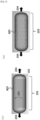
- Fig. 1 illustrates a cross-sectional view of the tank 101.
- the liner 102 comprises: a barrel part having a cylindrical shape; and dome parts having a domed shape provided at both ends of the barrel part, wherein each dome part is connected to an aperture.
- a material having gas permeability resistance such as aluminum, a steel, or a resin in order to retain a gas filled in the tank.
- the reinforcing layer 103 is formed by continuously winding resin-impregnated fiber bundles around the liner 102, and capable of exerting pressure resistance of the tank 101.
- the reinforcing layer 103 comprises a hoop layer placed in the liner 102 side, and a helical layer.
- a necessary pressure resistance can be exerted.
- the hoop layer and the helical layer are described.
- Fig. 2(a) is a schematic diagram illustrating one example of the hoop layer 201.
- the hoop layer 201 is formed by winding and layering resin-impregnated fiber bundles 403 around the cylindrical barrel part of the liner 102 at an angle(s) of 80° to 110° with respect to the axial direction 204 of the liner. Resin-impregnated fiber bundles are wound from one end to the other end of the barrel part at, for example, the layering angle shown in Fig. 2(a) to cover the whole barrel part.
- This molding pattern is defined as hoop winding, and this unit is regarded as one layer. By repeating the hoop winding, a necessary hoop layer thickness is obtained.
- the pressure resistance of the tank in the circumferential direction 202 is dependent on the thickness of the hoop layer 201 deposited.
- Fig. 2(b) is a schematic diagram illustrating one example of the helical layer 203.
- the helical layer 203 is formed by winding and layering resin-impregnated fiber bundles 403 at an angle(s) of more than 0° and less than 80°, or more than 110° and less than 180° with respect to the axial direction 204 of the liner.
- the molding pattern in which the dome parts and the barrel part are entirely covered at the layering angle is defined as helical winding, and this unit is regarded as one layer.
- the pressure resistance of the tank in the axial direction 204 is dependent on the thickness of the helical layer 203 deposited.
- the tank 101 illustrated in Fig. 3 is prepared.
- gaps 402 between adjacent bundles of the resin-impregnated fiber bundles wound in the hoop layer 201 it is important to form gaps 402 between adjacent bundles of the resin-impregnated fiber bundles wound in the hoop layer 201, and to provide at least one site where the resin-impregnated fiber bundles 403 are wound without forming a gap between adjacent bundles in the helical layer 203.
- the fracture origin is required to be in the barrel part as described in KHKS0121 (2016).
- the reinforcing layer 103 is generally designed to have a thickness at which the pressure generated in the reinforcing layer 103 during filling with gas is higher in the circumferential direction 202 of the tank than in the axial direction 204 of the tank, such that the fracture origin is in the barrel part.
- the providing of the gaps in the helical layer 203 is useful for achieving the orderly fiber alignment, the presence of a large amount of gaps leads to formation of connected gaps as a large defect, and such a defect acts as an origin to decrease the pressure resistance of the tank 101.
- the pressure that acts on the helical layer 203 is lower than the pressure that acts on the hoop layer 201. Therefore, disturbance of the fiber alignment of the helical layer 203 does not lead to fracture of the tank 101.
- the resin constituting the tank 101 has a resin toughness value of not less than 1.0 MPa ⁇ m 0.5 .
- the resin toughness value is preferably not less than 1.4 MPa ⁇ m 0.5 .
- a gap between the resin-impregnated fiber bundles 403 acts as a fracture origin, so that the pressure resistance of the tank 101 decreases.
- the upper limit of the resin toughness value is preferably 3.0 Mpa ⁇ m 0.5 , more preferably 2.6 MPa ⁇ m 0.5 . In cases where the upper limit of the resin toughness value is within the preferred range described above, propagation of cracks generated upon application of a pressure can be suppressed, and therefore the pressure resistance required for the tank 101 can be easily secured.
- the gaps 402 between the resin-impregnated fiber bundles are preferably formed only in the hoop layer 201 in contact with the liner 102.
- the pressure generated in the tank reinforcing layer 103 upon filling with gas is higher in the inner layer than in the outer layer, and the highest pressure is applied to the layer in contact with the liner 102.
- the hoop layer 201 is preferably placed on the contact surface with the liner 102, which contact surface acts as the fracture origin.
- gaps between resin-impregnated fiber bundles 403 do not necessarily need to be formed in either a hoop layer 201 or a helical layer 203. This is because, since the pressure applied to the reinforcing layer is lower in the outer-side layers than in the innermost layer, the effect of disturbance of the alignment of the resin-impregnated fiber bundles 403 on the pressure resistance is low.
- the ratio of the total of the areas exposed from the gaps formed between adjacent bundles of the resin-impregnated fiber bundles 403 wound in the hoop layer 201 (which may be hereinafter referred to as "gap area between fiber bundles"), to the barrel surface area of the liner 102 as the inner shell is preferably more than 0% and less than 50%.
- the ratio is more preferably more than 0.01% and less than 45%. In cases where the ratio is within the preferred range described above, gaps can be secured in the hoop layer 201 while formation of a large defect by the gaps in the hoop layer 201 is unlikely, so that a decrease in the pressure resistance can be effectively prevented.
- the liner 102 comprises: a barrel part having a cylindrical shape, positioned in the inner side of tangent lines 401 which are the border lines between the straight barrel part of the tank and curved surfaces; and dome parts having a domed shape, provided at both ends of the barrel part, wherein each dome part is connected to an aperture.
- the barrel area of the liner 102 is the area of the barrel part having a cylindrical shape positioned in the inner side of tangent lines 401, and the area of the gaps 402 between the resin-impregnated fiber bundles is determined by subtracting the wound area of the resin-impregnated fiber bundles 403 from the barrel area. These areas can be measured by temporarily stopping the filament winding molding machine during the winding of the resin-impregnated fiber bundles 403 around the liner 102. After acquiring an appearance image of the liner 102, the gap area between the fiber bundles and the barrel area of the liner as the inner shell are calculated using imaging software, a measure, or the like.
- the calculation may be carried out by an automatic program using an algorithm such as the color difference, or by visual trimming of the image. It is not necessary to use a single image covering the whole liner 102, and a plurality of images may be used by connecting them.
- the tank after curing may be decomposed to measure the widths of the resin-impregnated fiber bundles 403 and the gaps 402 between the resin-impregnated fiber bundles.
- the tank 101 is cut along the axial direction 204 of the tank to separate the liner 102 from the reinforcing layer 103, and then an image of the reinforcing layer 103 is acquired from the liner 102 side. Thereafter, the gap area between the fiber bundles and the barrel area of the liner 102 as the inner shell are calculated. As long as the shape of the reinforcing layer 103 is retained, the separation of the reinforcing layer 103 may be carried out by applying a force between layers or blowing away the resin by application of heat.
- the present invention preferably satisfies the following relationships: 0 ⁇ Lmin / W ⁇ 0.5 and 0.01 ⁇ Lmax / W ⁇ 0.5 wherein Lmin represents the minimum value (mm) of the gaps 402 between the resin-impregnated fiber bundles formed in the reinforcing layer 103; Lmax represents the maximum value (mm) of the gaps 402 between those resin-impregnated fiber bundles; and W represents the average width (mm) of the resin-impregnated fiber bundles 403 adjacent to the gaps 402 between those resin-impregnated fiber bundles.
- the lower limit of Lmin/W is more preferably higher than 0.01, still more preferably higher than 0.05.
- the lower limit of Lmax/W is more preferably higher than 0.05, still more preferably higher than 0.06.
- the upper limit of Lmin/W is more preferably lower than 0.45, still more preferably lower than 0.4.
- the upper limit of Lmax/W is more preferably lower than 0.45, still more preferably lower than 0.4.
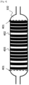
- the gaps 402 between the resin-impregnated fiber bundles and the widths of the resin-impregnated fiber bundles 403 are described using Fig. 5 .
- the gaps 402 between the resin-impregnated fiber bundles and the widths of the resin-impregnated fiber bundles 403 can be measured by temporarily stopping the filament winding molding machine during the winding of the resin-impregnated fiber bundles 403 around the liner 102. After visually finding the largest gap 601 between the resin-impregnated fiber bundles (which may be hereinafter referred to as "largest gap”), the gap is measured.
- the method of the measurement is not limited as long as the gap can be measured, and examples of the method include use of a caliper of a laser sensor.
- gaps 402 between the resin-impregnated fiber bundles are observed along the axial direction 204 of the liner.
- the width of the largest gap 601 described above is defined as Lmax
- the width of the smallest gap 603 between the resin-impregnated fiber bundles along the same axial direction 204 as in the case of the largest gap 601 (which may be hereinafter referred to as "smallest gap”) is defined as Lmin.
- the widths of the resin-impregnated fiber bundles 403 adjacent to the largest gap 601 are measured (at two sites), and the widths of the resin-impregnated fiber bundles 403 adj acent to the smallest gap 603 are measured by the same method.
- the measured values of the widths at the four sites are averaged to provide the average width W of the resin-impregnated fiber bundles 403.
- Lmin/W and Lmax/W are calculated using the Lmin, Lmax, and W obtained.
- Lmin is defined as 0.
- the average width W of the resin-impregnated fiber bundles 403 is the average of only the widths (at two sites) of the resin-impregnated fiber bundles 403 adjacent to the largest gap. Further, in cases where no gap is present for resin-impregnated fiber bundles 403 at both ends of the largest gap of the resin-impregnated fiber bundles, the average width W of the resin-impregnated fiber bundles 403 is defined as "none". In cases where the average width W of the resin-impregnated fiber bundles 403 is "none", Lmin/W and Lmax/W at the measurement site are defined as no value.
- the gaps 402 formed between the resin-impregnated fiber bundles in the hoop layer 201 it is important that there is at least one site where the fiber bundles are wound without forming the gaps.
- gaps are formed in the hoop layer 201, there is no overlap between the resin-impregnated fiber bundles 403, so that a uniform tension is applied to the resin-impregnated fiber bundles 403, and therefore an orderly fiber alignment can be achieved.
- cracks generated due to application of a pressure may propagate in the whole tank 101, resulting in fracture even at a low pressure.
- the at least one site where the resin-impregnated fiber bundles are wound without forming a gap is absent, the propagation of the cracks is not suppressed, so that the pressure resistance of the tank 101 cannot be improved.
- the weight ratio of the resin contained in the reinforcing layer 103 is more preferably 22.5% to 28.5%.
- the amount of the resin in the resin-impregnated fiber bundles 403 is sufficient, so that the gaps formed between the resin-impregnated fiber bundles 403 are unlikely to remain as voids, and a decrease in the pressure resistance can therefore be effectively prevented.
- the resin-impregnated fiber bundles 403 are unlikely to expand during winding of the fiber bundles around the liner, so that the gaps can be easily stably formed.
- the resin viscosity of the resin used in the present invention is preferably 10 to 150 Pa ⁇ s at 25°C.
- the resin-impregnated fiber bundles 403 are unlikely to expand during winding of the fiber bundles around the liner, so that the gaps can be easily stably formed.
- the gaps formed between the resin-impregnated fiber bundles 403 hardly remain as voids, so that a decrease in the pressure resistance can be effectively prevented.
- Examples of the fibers constituting the fiber bundles used in the present invention include glass fibers, carbon fibers, graphite fibers, aramid fibers, boron fibers, alumina fibers, and silicon carbide fibers. A mixture of two or more kinds of these reinforcing fibers may also be used. In a preferred mode, in order to obtain a molding having higher strength, carbon fibers are used as the fiber bundles.
- any type of carbon fibers may be used depending on the use. From the viewpoint of obtaining a molding having higher strength, carbon fibers having a tension modulus of 3 to 8 GPa in a strand tension test according to the method described in JIS R 7601 (1986) are preferably used.
- the resin used in the present invention is preferably a liquid-form resin. More specifically, from the viewpoint of obtaining the heat resistance and the environmental resistance required for the tank, the resin is preferably an epoxy resin composition containing an epoxy resin and a hardener. Further, when appropriate, a curing catalyst may be added for reducing the curing time.
- Fig. 6 is a schematic diagram illustrating the entire configuration of one example of a molding flow in the method of producing the tank of the present invention.
- the molding flow 701 mainly illustrates that:
- bobbin 702 only one bobbin 702 is shown.
- the molding flow 701 is not limited to such a case, and a plurality of bobbins 702 may be arranged.
- a tow prepreg preliminarily impregnated with a resin in a separate process may be used.
- the resin impregnation process can be omitted.
- the tank produced in the present invention can be preferably used not only for hydrogen gas vehicles and natural gas vehicles, but also for ships, aircraft, and the like, stationary tanks immobilized on the ground, and air respirators to be used in hospitals or by firemen.
- substances that may be stored in this tank include gases such as nitrogen, oxygen, argon, liquefied petroleum gas, and hydrogen; and liquefied products of these substances.
- the uncured resin to be used for the tank was defoamed under vacuum, and was then cured for the lengths of time and at the temperatures described in Examples and Comparative Examples in a mold whose thickness was set to 6 mm using a spacer made of "Teflon (registered trademark)" having a thickness of 6 mm, to obtain resin hardened plates having a thickness of 6 mm.
- the viscosity of the uncured resin to be used for the tank was measured according to the "method of measuring the viscosity with a cone-flat plate type rotational viscometer” in JIS Z8803 (2011) using an E-type viscometer (TVE-22HT, manufactured by Toki Sangyo Co., Ltd.) equipped with a standard cone rotor (1°34' ⁇ R24), at 25°C at a rotational speed of 5 rotations/minute. The viscosity was measured five times, and the resulting average was employed.
- a tow prepreg production apparatus comprising a creel, a kiss-roll, a nip-roll, and a winder
- a carbon fiber "TORAYCA” registered trademark
- TORAYCA registered trademark
- tow prepreg bobbin 2300 m of the tow prepreg was wound around a paper core with an initial tension of 600 to 1000 gf at a winding ratio of 6 to 10 such that a cylindrical shape having a winding width of 230 to 260 mm was formed.
- photographs of the liner on which resin-impregnated fiber bundles are wound are taken using a camera (IXY650, manufactured by Canon). This operation is carried out each time when the liner is rotated at 90°, 180°, and 270° in the circumferential direction, to take photographs.
- An acquired image is read using image processing software Image J (http://imagej.nih.gov/ij/). While visually identifying resin-impregnated fiber bundle portions, the area is calculated using polygon and Measure in this software. Subsequently, by the same method, the barrel area of the liner is calculated from the image.
- the area of the resin-impregnated fiber bundles is subtracted from the barrel area of the liner to calculate the gap area between the fiber bundles.
- the gap area between the fiber bundles and the barrel area of the liner are calculated for each of the remaining acquired images. Finally, from the remaining images acquired by averaging the calculated areas, the gap area between the fiber bundles and the barrel area of the liner were determined.
- the largest site is visually found, and the width of the site is measured using a caliper (Pocket Caliper 100 mm, manufactured by Shinwa Rules Co., Ltd.). Using this gap as a starting point, gaps between the resin-impregnated fiber bundles were observed along the axial direction of the liner. The maximum value (Lmax) of the gaps between the resin-impregnated fiber bundles and the minimum value (Lmin) of the gaps between the resin-impregnated fiber bundles were measured.
- the widths of the resin-impregnated fiber bundles adj acent to the Lmax are measured (at two sites), and the widths of the resin-impregnated fiber bundles adjacent to the Lmin are measured by the same method.
- the measured values of the widths at the four sites are averaged to provide the average width W of the resin-impregnated fiber bundles.
- the gap is defined as 0, and the average width of the resin-impregnated fiber bundles is defined as the average of only the widths (at two sites) of the resin-impregnated fiber bundles adjacent to the largest gap.
- the average width of the resin-impregnated fiber bundles is defined as "none".
- Lmin/W and Lmax/W at the measurement site are defined as no value, and not included in the measurement result.
- a point rotationally shifted at an angle of about 1° in the circumferential direction of the liner from the gap used as the starting point is used as a starting point from which the gaps between the resin-impregnated fiber bundles are observed along the axial direction of the liner.
- the maximum value of the gaps between the resin-impregnated fiber bundles is defined as Lmax, and the minimum value of the gaps between the resin-impregnated fiber bundles is defined as Lmin.
- the width W of the resin-impregnated fiber bundles is measured by the method described above, and Lmin/W and Lmax/W are calculated. This measurement is repeated for the entire circumference of the liner, and the maximum Lmax/W and the minimum Lmin/W are calculated among the obtained results. In cases where no gap is present between the resin-impregnated fiber bundles in the entire circumference of the measurement range, both Lmin/W and Lmax/W are defined as 0.
- a resin composition was obtained by stirring and mixing 88 parts by mass of "jER (registered trademark)” 828, 12 parts by mass of “Deconal (registered trademark)” EX821, 4 parts by mass of "Hypro (registered trademark)” 1300 ⁇ 8 as a carboxy-modified acrylic rubber, 17 parts by mass of "KANACE (registered trademark)” MX125, 7.4 parts by mass of DICY7T as dicyanodiamide, and 2.7 parts by mass of DCMU99 as an aromatic urea compound.
- the fracture toughness value of this resin composition was evaluated according to the "Method of Evaluating Fracture Toughness Value of Resin Used for Tank". As a result, the fracture toughness value was found to be 2.1 MPa ⁇ m 0.5 .
- a tow prepreg having a resin content of 24% was prepared.
- the strand strength of the carbon fibers used was 6200 MPa.
- a 7.5-L aluminum liner having an outer diameter of 160 mm was placed, and the tow prepreg was wound around the whole liner.
- a hoop layer was wound to a thickness of 0.79 mm at 89°/91° with respect to the axial direction of the liner.
- the tow prepreg was arranged such that adjacent tow prepregs did not overlap with each other, to provide periodic gaps in the first layer.
- Lmin/W and Lmax/W were calculated according to the "Calculation of Minimum Value Lmin of Gaps between Resin-Impregnated Fiber Bundles, Maximum Value Lmax of Those Gaps, and Average Width W of Resin-Impregnated Fiber Bundles Adjacent to Those Gaps".
- Lmin/W was 0.1
- Lmax/W was 0.44.
- a helical layer was wound to a thickness of 1.07 mm at 18°/162° with respect to the axial direction of the liner.
- a hoop layer was wound to a thickness of 0.52 mm at 89°/91° with respect to the axial direction of the liner, to obtain an intermediate.
- the intermediate was cured at 150°C for 2 hours with rotation in a curing furnace, to obtain a tank.
- the strength utilization rate of the obtained tank was calculated according to the "Method of Calculating Strength Utilization Rate".
- the strength utilization rate was 98.3%; the bursting pressure was 71.5 MPa; and the theoretical strength was 72.7 MPa.
- a resin composition was obtained by stirring and mixing 21 parts by mass of "jER (registered trademark)” 828, 67 parts by mass of “jER (registered trademark)” 806, 5 parts by mass of "EPOTOTO (registered trademark)” YDF-2001, 7 parts by mass of TETRAD-X as a xylene diamine type epoxy resin, 7 parts by mass of "KANACE (registered trademark)” MX-125, 5 parts by mass of DICY7T as dicyanodiamide, and 4 parts by mass of DCMU99 as an aromatic urea compound.
- the fracture toughness value of this resin composition was evaluated according to the "Method of Evaluating Fracture Toughness Value of Resin Used for Tank". As a result, the fracture toughness value was found to be 1.6 MPa ⁇ m 0.5 .
- a tow prepreg having a resin content of 24% was prepared.
- the strand strength of the carbon fibers used was 5800 MPa.
- a 7.5-L aluminum liner having an outer diameter of 160 mm was placed, and the tow prepreg was wound around the whole liner.
- a hoop layer was wound to a thickness of 0.79 mm at 89°/91° with respect to the axial direction of the liner.
- Lmin/W and Lmax/W were calculated according to the "Calculation of Minimum Value Lmin of Gaps between Resin-Impregnated Fiber Bundles, Maximum Value Lmax of Those Gaps, and Average Width W of Resin-Impregnated Fiber Bundles Adjacent to Those Gaps".
- Lmin/W was 0.19
- Lmax/W was 0.45.
- a helical layer was wound to a thickness of 1.07 mm at 18°/162° with respect to the axial direction of the liner.
- a hoop layer was wound to a thickness of 0.52 mm at 89°/91° with respect to the axial direction of the liner, to obtain an intermediate.
- the intermediate was cured at 110°C for 10 hours with rotation in a curing furnace, to obtain a tank.
- the strength utilization rate of the obtained tank was calculated according to the "Method of Calculating Strength Utilization Rate".
- the strength utilization rate was 108.5%; the bursting pressure was 73.8 MPa; and the theoretical strength was 68.0 MPa.
- a tank was prepared by the same method as in Example 1 except that 0.5-mm gaps were formed between the resin-impregnated fiber bundles of the hoop layer in the first layer during molding. In this process, width variation of the resin-impregnated fiber bundles led to five "sites where no gap was formed" in which the fiber bundles were overlapping in the hoop layer of the first layer.
- Lmin/W and Lmax/W were calculated according to the "Calculation of Minimum Value Lmin of Gaps between Resin-Impregnated Fiber Bundles, Maximum Value Lmax of Those Gaps, and Average Width W of Resin-Impregnated Fiber Bundles Adjacent to Those Gaps". As a result, Lmin/W was 0, and Lmax/W was 0.1.
- the strength utilization rate of the obtained tank was calculated according to the "Method of Calculating Strength Utilization Rate".
- the strength utilization rate was 102.1%; the bursting pressure was 74.2 MPa; and the theoretical strength was 72.7 MPa.
- a tank was prepared by the same method as in Example 1 except that molding was carried out such that the resin-impregnated fiber bundles in the hoop layer of the first layer overlapped with each other by 2.5 mm each.
- both Lmin/W and Lmax/W were regarded as 0 according to the definition in the "Calculation of Minimum Value Lmin of Gaps between Resin-Impregnated Fiber Bundles, Maximum Value Lmax of Those Gaps, and Average Width W of Resin-Impregnated Fiber Bundles Adjacent to Those Gaps"
- the strength utilization rate of the obtained tank was calculated according to the "Method of Calculating Strength Utilization Rate".
- the strength utilization rate was 90.6%; the bursting pressure was 65.9 MPa; and the theoretical strength was 72.7 MPa.
- the presence of overlapping resin-impregnated fiber bundles resulted in a decrease in the strength utilization rate.
- a resin composition was obtained by stirring and mixing 75 parts by mass of "jER (registered trademark)" 828, 40 parts by mass of GAN (manufactured by Japan Explosives Industry Association), 8 parts by mass of DICY7T (manufactured by Mitsubishi Chemical Corporation) as a hardener, and 2 parts by mass of DCMU as a curing aid.
- jER registered trademark
- GAN manufactured by Japan Explosives Industry Association
- DICY7T manufactured by Mitsubishi Chemical Corporation
- DCMU 2 parts by mass of DCMU as a curing aid.
- the fracture toughness value of this resin composition was evaluated according to the "Method of Evaluating Fracture Toughness Value of Resin Used for Tank". As a result, the fracture toughness value was found to be 0.72 MPa ⁇ m 0.5 .
- a tow prepreg having a resin content of 24% was prepared.
- the strand strength of the carbon fibers used was 5800 MPa.
- a 7.5-L aluminum liner having an outer diameter of 160 mm was placed, and the tow prepreg was wound around the whole liner.
- a hoop layer was wound to a thickness of 0.79 mm at 89°/91° with respect to the axial direction of the liner.
- Lmin/W and Lmax/W were calculated according to the "Calculation of Minimum Value Lmin of Gaps between Resin-Impregnated Fiber Bundles, Maximum Value Lmax of Those Gaps, and Average Width W of Resin-Impregnated Fiber Bundles Adjacent to Those Gaps".
- Lmin/W was 0.09
- Lmax/W was 0.32.
- a helical layer was wound to a thickness of 1.07 mm at 18°/162° with respect to the axial direction of the liner.
- a hoop layer was wound to a thickness of 0.52 mm at 89°/91° with respect to the axial direction of the liner, to obtain an intermediate.
- the intermediate was cured at 110°C for 10 hours with rotation in a curing furnace, to obtain a tank.
- the strength utilization rate of the obtained tank was calculated according to the "Method of Calculating Strength Utilization Rate".
- the strength utilization rate was 79.0%; the bursting pressure was 53.7 MPa; and the theoretical strength was 68.0 MPa.
Landscapes
- Engineering & Computer Science (AREA)
- Mechanical Engineering (AREA)
- General Engineering & Computer Science (AREA)
- Chemical & Material Sciences (AREA)
- Composite Materials (AREA)
- Manufacturing & Machinery (AREA)
- Textile Engineering (AREA)
- Physics & Mathematics (AREA)
- Mathematical Physics (AREA)
- Moulding By Coating Moulds (AREA)
- Filling Or Discharging Of Gas Storage Vessels (AREA)
Abstract
Description
- The present invention relates to a tank made of a fiber reinforced plastic (FRP).
- An FRP is a composite material prepared by reinforcing a resin with reinforcing fibers. FRPs are widely used since they are capable of exerting strength and rigidity that are equivalent to or higher than those of metallic materials such as iron and aluminum while having less weights compared to the metallic materials.
- FRPs can be formed into various shapes such as flat panel shapes, H shapes, and cylindrical shapes. In particular, tanks to be used for storing a high-pressure gas or a liquid is generally produced by filament winding molding. The filament winding molding method is a molding method in which a fiber bundle wound on a bobbin is continuously unwound while applying tension thereto, and the fiber bundle is impregnated with a thermosetting resin, followed by winding the fiber bundle on a liner to form a reinforcing layer.
- In a tank prepared by the filament winding molding method, the presence of gaps between fiber bundles during molding may lead to decreased pressure resistance. Therefore, in general, the molding is carried out in a state where adjacent fiber bundles overlap with each other such that no gap is formed between fibers. However, in this method, irregularity occurs between portions where fiber bundles are overlapping and portions where fiber bundles are not overlapping, leading to a difference in the tension applied to the fiber bundles. This produces slack of fiber bundles to which lower tension is applied, resulting in disturbance of the alignment of the fiber bundles. As a result, the pressure resistance of the tank may decrease.
- Therefore, for example, Patent Document 1 proposes a method in which the mode of overlapping of fiber bundles is improved to prevent occurrence of irregularity due to overlapped fiber bundles, wherein fiber bundles having different thicknesses in the width direction are provided and molding is carried out such that thinner portions of the fiber bundles overlap with each other. Further, Patent Document 2 proposes a method in which flat fiber bundles are deformed into a square shape so as to prevent formation of gaps between bands during molding. Further, Patent Document 3 proposes a method of detecting gaps between bands during filament winding molding.
-
- [Patent Document 1]
JP 2015-209887 A - [Patent Document 2]
JP 2012-140997 A - [Patent Document 3]
JP 2017-7104 A - However, under circumstances requiring a high production rate, it is difficult to wind fiber bundles as in Patent Document 1 such that their side surfaces are joined together to prevent formation of gaps, or to deform flat fiber bundles into a square shape in the process as in Patent Document 2. Further, in a method of detecting gaps between fiber bundles during filament winding molding as described in Patent Document 3, a detection apparatus is necessary, so that the cost of the tank may increase.
- In view of such a background, the present invention provides an inexpensive tank for which the conventional operation of accurately arranging fiber bundles, an apparatus for detecting gaps between resin-impregnated fiber bundles, and the like are not required.
- In order to solve the above problems, the tank of the present invention has the following configuration.
A tank comprising: - a liner which is an inner shell; and
- a reinforcing layer covering the outer surface of the liner;
- the reinforcing layer is formed by continuously winding resin-impregnated fiber bundles around the liner,
- the reinforcing layer comprises a hoop layer placed in the liner side, and a helical layer,
- gaps are formed between adj acent bundles of the resin-impregnated fiber bundles wound in the hoop layer,
- there is at least one site where the resin-impregnated fiber bundles are wound without forming a gap between adjacent bundles in the helical layer, and
- the resin constituting the tank has a resin toughness value of not less than 1.0 MPa·m0.5.
- In the tank of the present invention, the gaps are preferably formed only in the hoop layer in contact with the liner.
- In the tank of the present invention, the ratio of the total of the areas exposed from the gaps formed between adj acent bundles of the resin-impregnated fiber bundles wound in the hoop layer, to the barrel surface area of the liner is preferably more than 0% and less than 50%.
- The tank of the present invention preferably satisfies the following relationships:

- The Lmin and W of the tank of the present invention preferably satisfy the following relationship:

- In the tank of the present invention, there is preferably at least one site where no gap is present between adj acent bundles of the resin-impregnated fiber bundles wound in the hoop layer.
- In the tank of the present invention, the weight ratio of the resin contained in the reinforcing layer is preferably 21% to 30%.
- In the tank of the present invention, the resin contained in the resin-impregnated fiber bundles preferably has a resin viscosity of 10 to 150 Pa s at 25°C.
- The present invention can provide an inexpensive tank for which the conventional operation of accurately arranging resin-impregnated fiber bundles, an apparatus for detecting gaps between resin-impregnated fiber bundles, and the like are not required.
-
-
Fig. 1 is a schematic diagram illustrating one example of a cross-sectional view of a tank. -
Fig. 2(a) is a schematic diagram illustrating one example of a hoop layer of a tank. -
Fig. 2(b) is a schematic diagram illustrating one example of a helical layer of a tank. -
Fig. 3 is a schematic diagram illustrating one example of a laminated structure of a tank. -
Fig. 4 is a schematic diagram illustrating one example of a tank comprising a hoop layer in contact with a liner, wherein fiber bundle gaps are formed in the hoop layer. -
Fig. 5 is a schematic diagram illustrating one example of a tank comprising a hoop layer in contact with a liner, wherein the hoop layer has one or more sites where no fiber bundle gap is formed. -
Fig. 6 is a schematic diagram illustrating one example of a production process of a tank. - Embodiments of the present invention are described below in order. The present embodiments are merely examples for carrying out the present invention, and the present invention is not limited to the present embodiments.
- A
tank 101 according to the present invention is atank 101 comprising: - a
liner 102 which is an inner shell; and - a reinforcing
layer 103 covering the outer surface of theliner 102, - the reinforcing
layer 103 is formed by continuously winding resin-impregnatedfiber bundles 403 around theliner 102, - the reinforcing
layer 103 comprises ahoop layer 201 placed in theliner 102 side, and ahelical layer 203, -
gaps 402 are formed between adjacent bundles of the resin-impregnated fiber bundles wound in thehoop layer 201, - there is at least one site where the resin-impregnated
fiber bundles 403 are wound without forming a gap between adjacent bundles in thehelical layer 203, and - the resin constituting the
tank 101 has a resin toughness value of not less than 1.0 MPa·m0.5. -
Fig. 1 illustrates a cross-sectional view of thetank 101. Theliner 102 comprises: a barrel part having a cylindrical shape; and dome parts having a domed shape provided at both ends of the barrel part, wherein each dome part is connected to an aperture. For thetank 101, it is preferred to use a material having gas permeability resistance such as aluminum, a steel, or a resin in order to retain a gas filled in the tank. - The reinforcing
layer 103 is formed by continuously winding resin-impregnated fiber bundles around theliner 102, and capable of exerting pressure resistance of thetank 101. - The reinforcing
layer 103 comprises a hoop layer placed in theliner 102 side, and a helical layer. By combining necessary numbers of hoop layers and helical layers at necessary angles to achieve a necessary thickness, a necessary pressure resistance can be exerted. Here, the hoop layer and the helical layer are described. -
Fig. 2(a) is a schematic diagram illustrating one example of thehoop layer 201. Thehoop layer 201 is formed by winding and layering resin-impregnatedfiber bundles 403 around the cylindrical barrel part of theliner 102 at an angle(s) of 80° to 110° with respect to theaxial direction 204 of the liner. Resin-impregnated fiber bundles are wound from one end to the other end of the barrel part at, for example, the layering angle shown inFig. 2(a) to cover the whole barrel part. This molding pattern is defined as hoop winding, and this unit is regarded as one layer. By repeating the hoop winding, a necessary hoop layer thickness is obtained. The pressure resistance of the tank in thecircumferential direction 202 is dependent on the thickness of thehoop layer 201 deposited. -
Fig. 2(b) is a schematic diagram illustrating one example of thehelical layer 203. Thehelical layer 203 is formed by winding and layering resin-impregnatedfiber bundles 403 at an angle(s) of more than 0° and less than 80°, or more than 110° and less than 180° with respect to theaxial direction 204 of the liner. The molding pattern in which the dome parts and the barrel part are entirely covered at the layering angle is defined as helical winding, and this unit is regarded as one layer. By repeating the helical winding, a necessary helical layer thickness is obtained. The pressure resistance of the tank in theaxial direction 204 is dependent on the thickness of thehelical layer 203 deposited. - Thus, by combination of the
hoop layer 201 and thehelical layer 203, thetank 101 illustrated inFig. 3 is prepared. - In the present invention, it is important to form
gaps 402 between adjacent bundles of the resin-impregnated fiber bundles wound in thehoop layer 201, and to provide at least one site where the resin-impregnatedfiber bundles 403 are wound without forming a gap between adjacent bundles in thehelical layer 203. - For securing safety upon fracture of the
tank 101, in some cases, the fracture origin is required to be in the barrel part as described in KHKS0121 (2016). For satisfying this requirement, the reinforcinglayer 103 is generally designed to have a thickness at which the pressure generated in the reinforcinglayer 103 during filling with gas is higher in thecircumferential direction 202 of the tank than in theaxial direction 204 of the tank, such that the fracture origin is in the barrel part. - Therefore, in cases where the resin-impregnated
fiber bundles 403 in thehoop layer 201 are not uniformly wound, in other words, in cases where the alignment is disturbed, strength expression of the resin-impregnatedfiber bundles 403 may be insufficient, so that the fracture expected by the design may not necessarily occur in the barrel part. In particular, in cases where the resin-impregnatedfiber bundles 403 wound around theliner 102 overlap with each other, a difference in the tension occurs between portions where the resin-impregnatedfiber bundles 403 are overlapping and portions where the resin-impregnatedfiber bundles 403 are not overlapping. This leads to looseness of the resin-impregnatedfiber bundles 403 having low tension, resulting in disturbance of the alignment. Therefore, it is important to formgaps 402 between adj acent bundles of the resin-impregnated fiber bundles wound in thehoop layer 201. Without such a configuration, the overlap between the resin-impregnatedfiber bundles 403 cannot be eliminated, so that the orderly fiber alignment cannot be achieved due to the difference in the tension of the resin-impregnated fiber bundles 403. - Further, it is important to provide at least one site where the resin-impregnated
fiber bundles 403 are wound without forming a gap between adjacent bundles in thehelical layer 203. Although the providing of the gaps in thehelical layer 203 is useful for achieving the orderly fiber alignment, the presence of a large amount of gaps leads to formation of connected gaps as a large defect, and such a defect acts as an origin to decrease the pressure resistance of thetank 101. During filling with gas, the pressure that acts on thehelical layer 203 is lower than the pressure that acts on thehoop layer 201. Therefore, disturbance of the fiber alignment of thehelical layer 203 does not lead to fracture of thetank 101. Thus, it is important to provide at least one site where the resin-impregnated fiber bundles are wound without forming a gap between adjacent bundles in thehelical layer 203. Without such a configuration, the formation of connected gaps in the whole reinforcinglayer 103 cannot be prevented. - Further, it is important that the resin constituting the
tank 101 has a resin toughness value of not less than 1.0 MPa·m0.5. The resin toughness value is preferably not less than 1.4 MPa·m0.5. In cases where the resin toughness value is less than 1.0 MPa·m0.5, a gap between the resin-impregnatedfiber bundles 403 acts as a fracture origin, so that the pressure resistance of thetank 101 decreases. The upper limit of the resin toughness value is preferably 3.0 Mpa·m0.5, more preferably 2.6 MPa·m0.5. In cases where the upper limit of the resin toughness value is within the preferred range described above, propagation of cracks generated upon application of a pressure can be suppressed, and therefore the pressure resistance required for thetank 101 can be easily secured. - Further, in the present invention, the
gaps 402 between the resin-impregnated fiber bundles are preferably formed only in thehoop layer 201 in contact with theliner 102. The pressure generated in thetank reinforcing layer 103 upon filling with gas is higher in the inner layer than in the outer layer, and the highest pressure is applied to the layer in contact with theliner 102. Thus, thehoop layer 201 is preferably placed on the contact surface with theliner 102, which contact surface acts as the fracture origin. In the outer side of thehelical layer 203 placed on theinnermost hoop layer 201 in the reinforcing layer, gaps between resin-impregnatedfiber bundles 403 do not necessarily need to be formed in either ahoop layer 201 or ahelical layer 203. This is because, since the pressure applied to the reinforcing layer is lower in the outer-side layers than in the innermost layer, the effect of disturbance of the alignment of the resin-impregnatedfiber bundles 403 on the pressure resistance is low. - In the present invention, the ratio of the total of the areas exposed from the gaps formed between adjacent bundles of the resin-impregnated
fiber bundles 403 wound in the hoop layer 201 (which may be hereinafter referred to as "gap area between fiber bundles"), to the barrel surface area of theliner 102 as the inner shell is preferably more than 0% and less than 50%. The ratio is more preferably more than 0.01% and less than 45%. In cases where the ratio is within the preferred range described above, gaps can be secured in thehoop layer 201 while formation of a large defect by the gaps in thehoop layer 201 is unlikely, so that a decrease in the pressure resistance can be effectively prevented. - Here, methods of measuring the gap area between the fiber bundles and the barrel area of the
liner 102 as the inner shell are described usingFig. 4 . Theliner 102 comprises: a barrel part having a cylindrical shape, positioned in the inner side oftangent lines 401 which are the border lines between the straight barrel part of the tank and curved surfaces; and dome parts having a domed shape, provided at both ends of the barrel part, wherein each dome part is connected to an aperture. The barrel area of theliner 102 is the area of the barrel part having a cylindrical shape positioned in the inner side oftangent lines 401, and the area of thegaps 402 between the resin-impregnated fiber bundles is determined by subtracting the wound area of the resin-impregnatedfiber bundles 403 from the barrel area. These areas can be measured by temporarily stopping the filament winding molding machine during the winding of the resin-impregnatedfiber bundles 403 around theliner 102. After acquiring an appearance image of theliner 102, the gap area between the fiber bundles and the barrel area of the liner as the inner shell are calculated using imaging software, a measure, or the like. In cases where the areas are calculated based on an image, the calculation may be carried out by an automatic program using an algorithm such as the color difference, or by visual trimming of the image. It is not necessary to use a single image covering thewhole liner 102, and a plurality of images may be used by connecting them. In cases where the measurement of thegaps 402 between the resin-impregnated fiber bundles is impossible during the molding, the tank after curing may be decomposed to measure the widths of the resin-impregnatedfiber bundles 403 and thegaps 402 between the resin-impregnated fiber bundles. More specifically, thetank 101 is cut along theaxial direction 204 of the tank to separate theliner 102 from the reinforcinglayer 103, and then an image of the reinforcinglayer 103 is acquired from theliner 102 side. Thereafter, the gap area between the fiber bundles and the barrel area of theliner 102 as the inner shell are calculated. As long as the shape of the reinforcinglayer 103 is retained, the separation of the reinforcinglayer 103 may be carried out by applying a force between layers or blowing away the resin by application of heat. - The present invention preferably satisfies the following relationships:

gaps 402 between the resin-impregnated fiber bundles formed in the reinforcinglayer 103; Lmax represents the maximum value (mm) of thegaps 402 between those resin-impregnated fiber bundles; and W represents the average width (mm) of the resin-impregnatedfiber bundles 403 adjacent to thegaps 402 between those resin-impregnated fiber bundles. In cases where Lmin/W and Lmax/W satisfy the preferred lower limits described above, sites where the resin-impregnatedfiber bundles 403 overlap with each other are less likely to be formed even by changes in the fiber bundle width due to looseness of the wound resin-impregnatedfiber bundles 403 or by shifts of the positions of the resin-impregnatedfiber bundles 403 due to bleed out of the resin during curing. Therefore, thegaps 402 between the resin-impregnated fiber bundles can be stably formed. In cases where Lmin/W and Lmax/W satisfy the preferred upper limits described above, large defects are less likely to be formed by thegaps 402 between the resin-impregnated fiber bundles, so that a decrease in the pressure resistance can be effectively prevented. The lower limit of Lmin/W is more preferably higher than 0.01, still more preferably higher than 0.05. The lower limit of Lmax/W is more preferably higher than 0.05, still more preferably higher than 0.06. The upper limit of Lmin/W is more preferably lower than 0.45, still more preferably lower than 0.4. The upper limit of Lmax/W is more preferably lower than 0.45, still more preferably lower than 0.4. - Here, the methods of measuring the
gaps 402 between the resin-impregnated fiber bundles and the widths of the resin-impregnatedfiber bundles 403 are described usingFig. 5 . Thegaps 402 between the resin-impregnated fiber bundles and the widths of the resin-impregnatedfiber bundles 403 can be measured by temporarily stopping the filament winding molding machine during the winding of the resin-impregnatedfiber bundles 403 around theliner 102. After visually finding thelargest gap 601 between the resin-impregnated fiber bundles (which may be hereinafter referred to as "largest gap"), the gap is measured. The method of the measurement is not limited as long as the gap can be measured, and examples of the method include use of a caliper of a laser sensor. Using the found largest gap as the starting point,gaps 402 between the resin-impregnated fiber bundles are observed along theaxial direction 204 of the liner. The width of thelargest gap 601 described above is defined as Lmax, and the width of thesmallest gap 603 between the resin-impregnated fiber bundles along the sameaxial direction 204 as in the case of the largest gap 601 (which may be hereinafter referred to as "smallest gap") is defined as Lmin. Subsequently, the widths of the resin-impregnatedfiber bundles 403 adjacent to thelargest gap 601 are measured (at two sites), and the widths of the resin-impregnatedfiber bundles 403 adj acent to thesmallest gap 603 are measured by the same method. The measured values of the widths at the four sites are averaged to provide the average width W of the resin-impregnated fiber bundles 403. Thereafter, Lmin/W and Lmax/W are calculated using the Lmin, Lmax, and W obtained. Here, in cases where anoverlap 605 is present between the resin-impregnated fiber bundles along theaxial direction 204 of the liner, Lmin is defined as 0. Here, in cases where Lmin is 0, the average width W of the resin-impregnatedfiber bundles 403 is the average of only the widths (at two sites) of the resin-impregnatedfiber bundles 403 adjacent to the largest gap. Further, in cases where no gap is present for resin-impregnatedfiber bundles 403 at both ends of the largest gap of the resin-impregnated fiber bundles, the average width W of the resin-impregnatedfiber bundles 403 is defined as "none". In cases where the average width W of the resin-impregnatedfiber bundles 403 is "none", Lmin/W and Lmax/W at the measurement site are defined as no value. Subsequently, a point rotationally shifted at an angle of about 1° in thecircumferential direction 202 of the liner from the gap used as the starting point of the measurement is used as a starting point from which Lmin/W and Lmax/W are measured along theaxial direction 204 of the liner by the method described above. This measurement is repeated for the entire circumference in thecircumferential direction 202 of the liner, and the minimum Lmin/W and the maximum Lmax/W are determined among all obtained measured values. In cases where no gap is present between the resin-impregnatedfiber bundles 403 at any of the measurement sites, both Lmin/W and Lmax/W are defined as 0. - In the present invention, regarding the
gaps 402 formed between the resin-impregnated fiber bundles in thehoop layer 201, it is important that there is at least one site where the fiber bundles are wound without forming the gaps. In cases where gaps are formed in thehoop layer 201, there is no overlap between the resin-impregnatedfiber bundles 403, so that a uniform tension is applied to the resin-impregnatedfiber bundles 403, and therefore an orderly fiber alignment can be achieved. However, cracks generated due to application of a pressure may propagate in thewhole tank 101, resulting in fracture even at a low pressure. Thus, in cases the at least one site where the resin-impregnated fiber bundles are wound without forming a gap is absent, the propagation of the cracks is not suppressed, so that the pressure resistance of thetank 101 cannot be improved. - Further, in the present invention, the weight ratio of the resin contained in the reinforcing layer 103 (= the weight of the matrix resin in the resin-impregnated
fiber bundles 403/the whole weight of the resin-impregnated fiber bundles 403) is preferably 21 to 30%. The weight ratio of the resin contained in the reinforcinglayer 103 is more preferably 22.5% to 28.5%. In cases where the weight ratio of the resin contained in the reinforcinglayer 103 is within the preferred range described above, the amount of the resin in the resin-impregnatedfiber bundles 403 is sufficient, so that the gaps formed between the resin-impregnatedfiber bundles 403 are unlikely to remain as voids, and a decrease in the pressure resistance can therefore be effectively prevented. On the other hand, in such cases, the resin-impregnatedfiber bundles 403 are unlikely to expand during winding of the fiber bundles around the liner, so that the gaps can be easily stably formed. - The resin viscosity of the resin used in the present invention is preferably 10 to 150 Pa·s at 25°C. In cases where the resin viscosity is within the preferred range described above, the resin-impregnated
fiber bundles 403 are unlikely to expand during winding of the fiber bundles around the liner, so that the gaps can be easily stably formed. On the other hand, since resin impregnation can be easily allowed to proceed, the gaps formed between the resin-impregnatedfiber bundles 403 hardly remain as voids, so that a decrease in the pressure resistance can be effectively prevented. - The fiber bundles and the resin used in the present invention are described below.
- Examples of the fibers constituting the fiber bundles used in the present invention include glass fibers, carbon fibers, graphite fibers, aramid fibers, boron fibers, alumina fibers, and silicon carbide fibers. A mixture of two or more kinds of these reinforcing fibers may also be used. In a preferred mode, in order to obtain a molding having higher strength, carbon fibers are used as the fiber bundles.
- In the present invention, any type of carbon fibers may be used depending on the use. From the viewpoint of obtaining a molding having higher strength, carbon fibers having a tension modulus of 3 to 8 GPa in a strand tension test according to the method described in JIS R 7601 (1986) are preferably used.
- The resin used in the present invention is preferably a liquid-form resin. More specifically, from the viewpoint of obtaining the heat resistance and the environmental resistance required for the tank, the resin is preferably an epoxy resin composition containing an epoxy resin and a hardener. Further, when appropriate, a curing catalyst may be added for reducing the curing time.
- One example of the filament winding molding machine used in the present invention is illustrated in
Fig. 6. Fig. 6 is a schematic diagram illustrating the entire configuration of one example of a molding flow in the method of producing the tank of the present invention. - The
molding flow 701 mainly illustrates that: - a
creel roller 704 that plays a role in a sending process for sending afiber bundle 703 from abobbin 702; - a resin impregnation section that plays a role in a resin impregnation process for impregnating the
fiber bundle 703 with a resin, the section comprising aresin impregnation roller 705, aresin impregnation tank 706, and aguide roller 707; - a
feed eye 708 that plays a role in a winding process for winding the resin-impregnatedfiber bundle 703; - a
liner 102; and - a
fixed shaft 709 that connects a molding machine to theliner 102, - In Fig. 7, only one
bobbin 702 is shown. However, themolding flow 701 is not limited to such a case, and a plurality ofbobbins 702 may be arranged. - As the
bobbin 702, a tow prepreg preliminarily impregnated with a resin in a separate process may be used. In cases where a tow prepreg is used, the resin impregnation process can be omitted. - The tank produced in the present invention can be preferably used not only for hydrogen gas vehicles and natural gas vehicles, but also for ships, aircraft, and the like, stationary tanks immobilized on the ground, and air respirators to be used in hospitals or by firemen. Examples of substances that may be stored in this tank include gases such as nitrogen, oxygen, argon, liquefied petroleum gas, and hydrogen; and liquefied products of these substances.
- The uncured resin to be used for the tank was defoamed under vacuum, and was then cured for the lengths of time and at the temperatures described in Examples and Comparative Examples in a mold whose thickness was set to 6 mm using a spacer made of "Teflon (registered trademark)" having a thickness of 6 mm, to obtain resin hardened plates having a thickness of 6 mm. Each obtained resin hardened plate was processed into the test piece shape described in ASTM D5045-99, and then an SENB test was carried out according to ASTM D5045-99. The test was carried out for 16 samples (n=16), and the resulting average was employed as the fracture toughness value.
- The viscosity of the uncured resin to be used for the tank was measured according to the "method of measuring the viscosity with a cone-flat plate type rotational viscometer" in JIS Z8803 (2011) using an E-type viscometer (TVE-22HT, manufactured by Toki Sangyo Co., Ltd.) equipped with a standard cone rotor (1°34' × R24), at 25°C at a rotational speed of 5 rotations/minute. The viscosity was measured five times, and the resulting average was employed.
- Using a tow prepreg production apparatus comprising a creel, a kiss-roll, a nip-roll, and a winder, one side of a carbon fiber "TORAYCA" (registered trademark) was coated with a resin composition whose temperature was adjusted to 25°C, and then the carbon fiber was passed through the nip-roll to allow impregnation of the inside of the fiber bundle with the resin composition, to thereby obtain a tow prepreg. Regarding the tow prepreg bobbin, 2300 m of the tow prepreg was wound around a paper core with an initial tension of 600 to 1000 gf at a winding ratio of 6 to 10 such that a cylindrical shape having a winding width of 230 to 260 mm was formed.
- After stopping the filament winding molding machine during molding, photographs of the liner on which resin-impregnated fiber bundles are wound are taken using a camera (IXY650, manufactured by Canon). This operation is carried out each time when the liner is rotated at 90°, 180°, and 270° in the circumferential direction, to take photographs. An acquired image is read using image processing software Image J (http://imagej.nih.gov/ij/). While visually identifying resin-impregnated fiber bundle portions, the area is calculated using polygon and Measure in this software. Subsequently, by the same method, the barrel area of the liner is calculated from the image. Thereafter, the area of the resin-impregnated fiber bundles is subtracted from the barrel area of the liner to calculate the gap area between the fiber bundles. By carrying out the same process, the gap area between the fiber bundles and the barrel area of the liner are calculated for each of the remaining acquired images. Finally, from the remaining images acquired by averaging the calculated areas, the gap area between the fiber bundles and the barrel area of the liner were determined.
- After stopping the filament winding molding machine during molding, the largest site is visually found, and the width of the site is measured using a caliper (Pocket Caliper 100 mm, manufactured by Shinwa Rules Co., Ltd.). Using this gap as a starting point, gaps between the resin-impregnated fiber bundles were observed along the axial direction of the liner. The maximum value (Lmax) of the gaps between the resin-impregnated fiber bundles and the minimum value (Lmin) of the gaps between the resin-impregnated fiber bundles were measured. Subsequently, the widths of the resin-impregnated fiber bundles adj acent to the Lmax are measured (at two sites), and the widths of the resin-impregnated fiber bundles adjacent to the Lmin are measured by the same method. The measured values of the widths at the four sites are averaged to provide the average width W of the resin-impregnated fiber bundles. However, in cases where there is no minimum value (Lmin) of the gaps between the fiber bundles at the measurement site, the gap is defined as 0, and the average width of the resin-impregnated fiber bundles is defined as the average of only the widths (at two sites) of the resin-impregnated fiber bundles adjacent to the largest gap. Further, in cases where no gap is present for resin-impregnated fiber bundles at both ends of the largest gap of the resin-impregnated fiber bundles, the average width of the resin-impregnated fiber bundles is defined as "none". In cases where the average width of the resin-impregnated fiber bundles is "none", Lmin/W and Lmax/W at the measurement site are defined as no value, and not included in the measurement result. Subsequently, a point rotationally shifted at an angle of about 1° in the circumferential direction of the liner from the gap used as the starting point is used as a starting point from which the gaps between the resin-impregnated fiber bundles are observed along the axial direction of the liner. The maximum value of the gaps between the resin-impregnated fiber bundles is defined as Lmax, and the minimum value of the gaps between the resin-impregnated fiber bundles is defined as Lmin. Thereafter, the width W of the resin-impregnated fiber bundles is measured by the method described above, and Lmin/W and Lmax/W are calculated. This measurement is repeated for the entire circumference of the liner, and the maximum Lmax/W and the minimum Lmin/W are calculated among the obtained results. In cases where no gap is present between the resin-impregnated fiber bundles in the entire circumference of the measurement range, both Lmin/W and Lmax/W are defined as 0.
- By the method described in KHKS0121 (2005), a water pressure was applied in the tank to perform a bursting test, to measure the pressure at the time of bursting. According to the equation of MIL-HDBK-17-3F Volume 3 of 5 17 HUNE 2002 5.3.5.3.1(e), the strength of the tank was calculated (hereinafter referred to as theoretical strength), and the strength utilization rate of the tank was calculated according to the following equation.

- The present invention is described below in more detail by way of Examples.
- A resin composition was obtained by stirring and mixing 88 parts by mass of "jER (registered trademark)" 828, 12 parts by mass of "Deconal (registered trademark)" EX821, 4 parts by mass of "Hypro (registered trademark)" 1300×8 as a carboxy-modified acrylic rubber, 17 parts by mass of "KANACE (registered trademark)" MX125, 7.4 parts by mass of DICY7T as dicyanodiamide, and 2.7 parts by mass of DCMU99 as an aromatic urea compound.
- The fracture toughness value of this resin composition was evaluated according to the "Method of Evaluating Fracture Toughness Value of Resin Used for Tank". As a result, the fracture toughness value was found to be 2.1 MPa·m0.5. Using this resin composition and carbon fibers "TORAYCA (registered trademark)" T910SC-36K-50C, a tow prepreg having a resin content of 24% was prepared. The strand strength of the carbon fibers used was 6200 MPa. In the filament winding molding machine, a 7.5-L aluminum liner having an outer diameter of 160 mm was placed, and the tow prepreg was wound around the whole liner. As a first layer, a hoop layer was wound to a thickness of 0.79 mm at 89°/91° with respect to the axial direction of the liner. In this process, the tow prepreg was arranged such that adjacent tow prepregs did not overlap with each other, to provide periodic gaps in the first layer. At this time, Lmin/W and Lmax/W were calculated according to the "Calculation of Minimum Value Lmin of Gaps between Resin-Impregnated Fiber Bundles, Maximum Value Lmax of Those Gaps, and Average Width W of Resin-Impregnated Fiber Bundles Adjacent to Those Gaps". As a result, Lmin/W was 0.1, and Lmax/W was 0.44. As a second layer, a helical layer was wound to a thickness of 1.07 mm at 18°/162° with respect to the axial direction of the liner. Further, as a third layer, a hoop layer was wound to a thickness of 0.52 mm at 89°/91° with respect to the axial direction of the liner, to obtain an intermediate. The intermediate was cured at 150°C for 2 hours with rotation in a curing furnace, to obtain a tank.
- The strength utilization rate of the obtained tank was calculated according to the "Method of Calculating Strength Utilization Rate". The strength utilization rate was 98.3%; the bursting pressure was 71.5 MPa; and the theoretical strength was 72.7 MPa.
- A resin composition was obtained by stirring and mixing 21 parts by mass of "jER (registered trademark)" 828, 67 parts by mass of "jER (registered trademark)" 806, 5 parts by mass of "EPOTOTO (registered trademark)" YDF-2001, 7 parts by mass of TETRAD-X as a xylene diamine type epoxy resin, 7 parts by mass of "KANACE (registered trademark)" MX-125, 5 parts by mass of DICY7T as dicyanodiamide, and 4 parts by mass of DCMU99 as an aromatic urea compound.
- The fracture toughness value of this resin composition was evaluated according to the "Method of Evaluating Fracture Toughness Value of Resin Used for Tank". As a result, the fracture toughness value was found to be 1.6 MPa·m0.5. Using this resin composition and carbon fibers "TORAYCA (registered trademark)" T720SC-36K-50C, a tow prepreg having a resin content of 24% was prepared. The strand strength of the carbon fibers used was 5800 MPa. In the filament winding molding machine, a 7.5-L aluminum liner having an outer diameter of 160 mm was placed, and the tow prepreg was wound around the whole liner. As a first layer, a hoop layer was wound to a thickness of 0.79 mm at 89°/91° with respect to the axial direction of the liner. At this time, Lmin/W and Lmax/W were calculated according to the "Calculation of Minimum Value Lmin of Gaps between Resin-Impregnated Fiber Bundles, Maximum Value Lmax of Those Gaps, and Average Width W of Resin-Impregnated Fiber Bundles Adjacent to Those Gaps". As a result, Lmin/W was 0.19, and Lmax/W was 0.45. As a second layer, a helical layer was wound to a thickness of 1.07 mm at 18°/162° with respect to the axial direction of the liner. Further, as a third layer, a hoop layer was wound to a thickness of 0.52 mm at 89°/91° with respect to the axial direction of the liner, to obtain an intermediate. The intermediate was cured at 110°C for 10 hours with rotation in a curing furnace, to obtain a tank.
- The strength utilization rate of the obtained tank was calculated according to the "Method of Calculating Strength Utilization Rate". The strength utilization rate was 108.5%; the bursting pressure was 73.8 MPa; and the theoretical strength was 68.0 MPa.
- A tank was prepared by the same method as in Example 1 except that 0.5-mm gaps were formed between the resin-impregnated fiber bundles of the hoop layer in the first layer during molding. In this process, width variation of the resin-impregnated fiber bundles led to five "sites where no gap was formed" in which the fiber bundles were overlapping in the hoop layer of the first layer. At this time, Lmin/W and Lmax/W were calculated according to the "Calculation of Minimum Value Lmin of Gaps between Resin-Impregnated Fiber Bundles, Maximum Value Lmax of Those Gaps, and Average Width W of Resin-Impregnated Fiber Bundles Adjacent to Those Gaps". As a result, Lmin/W was 0, and Lmax/W was 0.1.
- Subsequently, the strength utilization rate of the obtained tank was calculated according to the "Method of Calculating Strength Utilization Rate". The strength utilization rate was 102.1%; the bursting pressure was 74.2 MPa; and the theoretical strength was 72.7 MPa.
- A tank was prepared by the same method as in Example 1 except that molding was carried out such that the resin-impregnated fiber bundles in the hoop layer of the first layer overlapped with each other by 2.5 mm each. At this time, since no gap was formed in the hoop layer of the first layer, both Lmin/W and Lmax/W were regarded as 0 according to the definition in the "Calculation of Minimum Value Lmin of Gaps between Resin-Impregnated Fiber Bundles, Maximum Value Lmax of Those Gaps, and Average Width W of Resin-Impregnated Fiber Bundles Adjacent to Those Gaps"
- The strength utilization rate of the obtained tank was calculated according to the "Method of Calculating Strength Utilization Rate". The strength utilization rate was 90.6%; the bursting pressure was 65.9 MPa; and the theoretical strength was 72.7 MPa. Thus, the presence of overlapping resin-impregnated fiber bundles resulted in a decrease in the strength utilization rate.
- A resin composition was obtained by stirring and mixing 75 parts by mass of "jER (registered trademark)" 828, 40 parts by mass of GAN (manufactured by Japan Explosives Industry Association), 8 parts by mass of DICY7T (manufactured by Mitsubishi Chemical Corporation) as a hardener, and 2 parts by mass of DCMU as a curing aid.
- The fracture toughness value of this resin composition was evaluated according to the "Method of Evaluating Fracture Toughness Value of Resin Used for Tank". As a result, the fracture toughness value was found to be 0.72 MPa·m0.5. Using this resin composition and carbon fibers "TORAYCA (registered trademark)" T720SC-36K-50C, a tow prepreg having a resin content of 24% was prepared. The strand strength of the carbon fibers used was 5800 MPa. In the filament winding molding machine, a 7.5-L aluminum liner having an outer diameter of 160 mm was placed, and the tow prepreg was wound around the whole liner. As a first layer, a hoop layer was wound to a thickness of 0.79 mm at 89°/91° with respect to the axial direction of the liner. At this time, Lmin/W and Lmax/W were calculated according to the "Calculation of Minimum Value Lmin of Gaps between Resin-Impregnated Fiber Bundles, Maximum Value Lmax of Those Gaps, and Average Width W of Resin-Impregnated Fiber Bundles Adjacent to Those Gaps". As a result, Lmin/W was 0.09, and Lmax/W was 0.32. As a second layer, a helical layer was wound to a thickness of 1.07 mm at 18°/162° with respect to the axial direction of the liner. Further, as a third layer, a hoop layer was wound to a thickness of 0.52 mm at 89°/91° with respect to the axial direction of the liner, to obtain an intermediate. The intermediate was cured at 110°C for 10 hours with rotation in a curing furnace, to obtain a tank.
- The strength utilization rate of the obtained tank was calculated according to the "Method of Calculating Strength Utilization Rate". The strength utilization rate was 79.0%; the bursting pressure was 53.7 MPa; and the theoretical strength was 68.0 MPa. These results indicate that, when gaps are formed between the resin-impregnated fiber bundles and the fracture toughness value is low, the strength utilization rate decreases.
-
- 101: Tank
- 102: Liner
- 103: Reinforcing layer
- 201: Hoop layer
- 202: Circumferential direction
- 203: Helical layer
- 204: Tank axial direction
- 401: Tangent line
- 402: Gap between resin-impregnated fiber bundles
- 403: Resin-impregnated fiber bundle
- 601: Largest gap between resin-impregnated fiber bundles
- 602: Liner axial direction
- 603: Smallest gap between the resin-impregnated fiber bundles along the same axial direction as in the case of 601
- 604: Circumferential direction of the liner
- 605: Overlap of resin-impregnated fiber bundles
- 701: Molding flow
- 702: Bobbin
- 703: Fiber bundle
- 704: Creel roller
- 705: Resin impregnation roller
- 706: Resin impregnation tank
- 707: Guide roller
- 708: Feed Eye
- 709: Fixed shaft
Claims (8)
- A tank comprising:a liner which is an inner shell; anda reinforcing layer covering the outer surface of the liner;whereinthe reinforcing layer is formed by continuously winding resin-impregnated fiber bundles around the liner,the reinforcing layer comprises a hoop layer placed in the liner side, and a helical layer,gaps are formed between adj acent bundles of the resin-impregnated fiber bundles wound in the hoop layer,there is at least one site where the resin-impregnated fiber bundles are wound without forming a gap between adjacent bundles in the helical layer, andthe resin constituting the tank has a resin toughness value of not less than 1.0 MPam0.5.
- The tank according to claim 1, wherein the gaps are formed only in the hoop layer in contact with the liner.
- The tank according to claim 1 or 2, wherein the ratio of the total of the areas exposed from the gaps formed between adjacent bundles of the resin-impregnated fiber bundles wound in the hoop layer, to the barrel surface area of the liner is more than 0% and less than 50%.
- The tank according to any one of claims 1 to 3, which satisfies the following relationships:

- The tank according to claim 4, wherein Lmin and W satisfy the following relationship:

- The tank according to any one of claims 1 to 3, wherein there is at least one site where no gap is present between adjacent bundles of the resin-impregnated fiber bundles wound in the hoop layer.
- The tank according to any one of claims 1 to 6, wherein the weight ratio of the resin contained in the reinforcing layer is 21% to 30%.
- The tank according to any one of claims 1 to 7, wherein the resin contained in the resin-impregnated fiber bundles has a resin viscosity of 10 to 150 Pa s at 25°C.
Applications Claiming Priority (2)
| Application Number | Priority Date | Filing Date | Title |
|---|---|---|---|
| JP2020055302 | 2020-03-26 | ||
| PCT/JP2021/010286 WO2021193180A1 (en) | 2020-03-26 | 2021-03-15 | Tank |
Publications (2)
| Publication Number | Publication Date |
|---|---|
| EP4130519A1 true EP4130519A1 (en) | 2023-02-08 |
| EP4130519A4 EP4130519A4 (en) | 2024-06-05 |
Family
ID=77891898
Family Applications (1)
| Application Number | Title | Priority Date | Filing Date |
|---|---|---|---|
| EP21774637.9A Pending EP4130519A4 (en) | 2020-03-26 | 2021-03-15 | Tank |
Country Status (7)
| Country | Link |
|---|---|
| US (1) | US12085228B2 (en) |
| EP (1) | EP4130519A4 (en) |
| JP (1) | JP7661882B2 (en) |
| KR (1) | KR20220159364A (en) |
| CN (1) | CN115279576B (en) |
| TW (1) | TW202202761A (en) |
| WO (1) | WO2021193180A1 (en) |
Families Citing this family (3)
| Publication number | Priority date | Publication date | Assignee | Title |
|---|---|---|---|---|
| US20200347992A1 (en) * | 2019-05-02 | 2020-11-05 | Agility Fuel Systems Llc | Polymeric liner based gas cylinder with reduced permeability |
| US12358365B1 (en) | 2021-05-07 | 2025-07-15 | Agility Fuel Systems Llc | Vehicles having composite interwoven gas containment assemblies |
| WO2026015702A1 (en) * | 2024-07-10 | 2026-01-15 | Braindrip, Llc | Overwrapped composite vessels for the storage and transmission of gases |
Family Cites Families (19)
| Publication number | Priority date | Publication date | Assignee | Title |
|---|---|---|---|---|
| JPH09280496A (en) * | 1996-04-18 | 1997-10-31 | Toray Ind Inc | Pressure vessel and method of manufacturing the same |
| JP2009174700A (en) * | 2007-06-14 | 2009-08-06 | Toyota Motor Corp | Gas tank |
| JP2011248394A (en) * | 2010-05-21 | 2011-12-08 | Toyota Motor Corp | Strength analysis method of high pressure gas tank |
| WO2012043453A1 (en) | 2010-09-28 | 2012-04-05 | 東レ株式会社 | Epoxy resin composition, prepreg and fiber-reinforced compound material |
| JP5747763B2 (en) * | 2010-09-28 | 2015-07-15 | 東レ株式会社 | Epoxy resin composition, prepreg and fiber reinforced composite material |
| JP5510902B2 (en) | 2010-12-28 | 2014-06-04 | トヨタ自動車株式会社 | Manufacturing method of pressure vessel |
| JP6077489B2 (en) | 2014-04-25 | 2017-02-08 | 八千代工業株式会社 | Pressure vessel and filament winding method |
| JP6365429B2 (en) | 2015-06-16 | 2018-08-01 | トヨタ自動車株式会社 | Filament winding equipment |
| JP6254564B2 (en) * | 2015-11-18 | 2017-12-27 | トヨタ自動車株式会社 | Tank manufacturing method and tank |
| JP6222387B1 (en) * | 2015-12-10 | 2017-11-01 | 三菱ケミカル株式会社 | Toe prepreg, composite material reinforced pressure vessel, and method for manufacturing composite material reinforced pressure vessel |
| JP2017115938A (en) * | 2015-12-22 | 2017-06-29 | ニッタ株式会社 | High pressure vessel and method for manufacturing high pressure vessel |
| JPWO2018096905A1 (en) * | 2016-11-24 | 2019-10-17 | 東レ株式会社 | Manufacturing method of pressure vessel |
| JP6586965B2 (en) * | 2017-01-16 | 2019-10-09 | トヨタ自動車株式会社 | Tank manufacturing method |
| JP6813194B2 (en) * | 2017-01-20 | 2021-01-13 | サムテック株式会社 | Filament winding method and filament winding equipment for using it |
| JP6652087B2 (en) * | 2017-02-10 | 2020-02-19 | トヨタ自動車株式会社 | Gas tank and its manufacturing method |
| JP6790997B2 (en) * | 2017-04-28 | 2020-11-25 | トヨタ自動車株式会社 | How to manufacture high pressure tank |
| JP6834900B2 (en) * | 2017-10-20 | 2021-02-24 | トヨタ自動車株式会社 | How to manufacture high pressure tank |
| JP2020034121A (en) * | 2018-08-31 | 2020-03-05 | トヨタ自動車株式会社 | Tank manufacturing method |
| JP7078905B2 (en) * | 2019-01-16 | 2022-06-01 | トヨタ自動車株式会社 | Manufacturing method of high pressure tank |
-
2021
- 2021-03-15 US US17/911,984 patent/US12085228B2/en active Active
- 2021-03-15 JP JP2021518810A patent/JP7661882B2/en active Active
- 2021-03-15 CN CN202180020876.0A patent/CN115279576B/en active Active
- 2021-03-15 KR KR1020227031096A patent/KR20220159364A/en active Pending
- 2021-03-15 EP EP21774637.9A patent/EP4130519A4/en active Pending
- 2021-03-15 WO PCT/JP2021/010286 patent/WO2021193180A1/en not_active Ceased
- 2021-03-22 TW TW110110162A patent/TW202202761A/en unknown
Also Published As
| Publication number | Publication date |
|---|---|
| WO2021193180A1 (en) | 2021-09-30 |
| JP7661882B2 (en) | 2025-04-15 |
| CN115279576B (en) | 2024-07-12 |
| KR20220159364A (en) | 2022-12-02 |
| EP4130519A4 (en) | 2024-06-05 |
| TW202202761A (en) | 2022-01-16 |
| CN115279576A (en) | 2022-11-01 |
| US20230134272A1 (en) | 2023-05-04 |
| JPWO2021193180A1 (en) | 2021-09-30 |
| US12085228B2 (en) | 2024-09-10 |
Similar Documents
| Publication | Publication Date | Title |
|---|---|---|
| EP4130519A1 (en) | Tank | |
| EP2433045B1 (en) | High pressure storage device and method | |
| US20150192251A1 (en) | High pressure carbon composite pressure vessel | |
| JPWO2018096905A1 (en) | Manufacturing method of pressure vessel | |
| JP4639085B2 (en) | Pressure vessel and method for manufacturing the same | |
| JP7035976B2 (en) | High pressure tank and its mounting structure | |
| EP3135981B1 (en) | Pressure vessel and method for winding filament | |
| US20090095796A1 (en) | Wire wrapped pressure vessels | |
| US20200198260A1 (en) | Pressure vessel and manufacturing method thereof | |
| JP6895682B2 (en) | Manufacturing method of unidirectional prepreg, fiber reinforced thermoplastic resin sheet, unidirectional prepreg and fiber reinforced thermoplastic resin sheet, and molded article | |
| EP3795340A1 (en) | High pressure container and method of its manufacture | |
| US20170167661A1 (en) | Composite Material Container and the Forming Method of its Composite Material Layer | |
| KR102118285B1 (en) | Towpreg for filament winding and manufacturing method thereof | |
| JP2020153503A (en) | Pressure vessel inspection method | |
| JP4877153B2 (en) | Fiber-reinforced composite material molding method | |
| KR101794469B1 (en) | Resin composition for pressure vessel and pressure vessel including the same | |
| US20040028874A1 (en) | Fiber-reinforced plastic molded body and method of manufacturing the molded body | |
| WO2025202435A1 (en) | Gas tank and manufacturing method thereof | |
| US20240068618A1 (en) | High-pressure tank and manufacturing method of high-pressure tank | |
| JP7563150B2 (en) | Towpreg and method for manufacturing filament-wound molded product using towpreg | |
| JPH08303693A (en) | Fiber reinforced resin tank | |
| KR102692001B1 (en) | Towpreg and manufacturing method thereof | |
| EP4711120A1 (en) | Method for producing cryogenic tank | |
| KR102925289B1 (en) | High pressure container with boss reinforced winding and menufacturing method thereof | |
| JP2008307720A (en) | Fiber reinforced composite material method and fiber reinforced composite material |
Legal Events
| Date | Code | Title | Description |
|---|---|---|---|
| STAA | Information on the status of an ep patent application or granted ep patent |
Free format text: STATUS: THE INTERNATIONAL PUBLICATION HAS BEEN MADE |
|
| PUAI | Public reference made under article 153(3) epc to a published international application that has entered the european phase |
Free format text: ORIGINAL CODE: 0009012 |
|
| STAA | Information on the status of an ep patent application or granted ep patent |
Free format text: STATUS: REQUEST FOR EXAMINATION WAS MADE |
|
| 17P | Request for examination filed |
Effective date: 20220920 |
|
| AK | Designated contracting states |
Kind code of ref document: A1 Designated state(s): AL AT BE BG CH CY CZ DE DK EE ES FI FR GB GR HR HU IE IS IT LI LT LU LV MC MK MT NL NO PL PT RO RS SE SI SK SM TR |
|
| DAV | Request for validation of the european patent (deleted) | ||
| DAX | Request for extension of the european patent (deleted) | ||
| A4 | Supplementary search report drawn up and despatched |
Effective date: 20240503 |
|
| RIC1 | Information provided on ipc code assigned before grant |
Ipc: F17C 1/16 20060101ALN20240427BHEP Ipc: B29L 31/00 20060101ALN20240427BHEP Ipc: B29C 70/08 20060101ALI20240427BHEP Ipc: B29C 53/60 20060101ALI20240427BHEP Ipc: B29C 63/10 20060101ALI20240427BHEP Ipc: B29C 70/32 20060101ALI20240427BHEP Ipc: B29C 63/06 20060101ALI20240427BHEP Ipc: B29C 70/16 20060101ALI20240427BHEP Ipc: B29C 70/00 20060101ALI20240427BHEP Ipc: F17C 1/06 20060101ALI20240427BHEP Ipc: F16J 12/00 20060101AFI20240427BHEP |