EP4130388B1 - Beheizter bodenbelag, der für den aussenbereich geeignet ist - Google Patents
Beheizter bodenbelag, der für den aussenbereich geeignet ist Download PDFInfo
- Publication number
- EP4130388B1 EP4130388B1 EP22188596.5A EP22188596A EP4130388B1 EP 4130388 B1 EP4130388 B1 EP 4130388B1 EP 22188596 A EP22188596 A EP 22188596A EP 4130388 B1 EP4130388 B1 EP 4130388B1
- Authority
- EP
- European Patent Office
- Prior art keywords
- heating
- flooring according
- rectilinear grooves
- floor mat
- heat
- Prior art date
- Legal status (The legal status is an assumption and is not a legal conclusion. Google has not performed a legal analysis and makes no representation as to the accuracy of the status listed.)
- Active
Links
Images
Classifications
-
- E—FIXED CONSTRUCTIONS
- E01—CONSTRUCTION OF ROADS, RAILWAYS, OR BRIDGES
- E01H—STREET CLEANING; CLEANING OF PERMANENT WAYS; CLEANING BEACHES; DISPERSING OR PREVENTING FOG IN GENERAL CLEANING STREET OR RAILWAY FURNITURE OR TUNNEL WALLS
- E01H5/00—Removing snow or ice from roads or like surfaces; Grading or roughening snow or ice
- E01H5/10—Removing snow or ice from roads or like surfaces; Grading or roughening snow or ice by application of heat for melting snow or ice, whether cleared or not, combined or not with clearing or removing mud or water, e.g. burners for melting in situ, heated clearing instruments ; Cleaning snow by blowing or suction only
Definitions
- the present invention relates to the technical field of heated floor coverings, suitable for outdoor use.
- the protective measures then generally consist of either clearing this traffic space, for example using a shovel, or applying a snow removal agent, such as snow salt.
- the present invention proposes a heating covering for the floor, suitable for outdoor use.
- the solution according to the invention makes it possible to maintain a frost-free ground surface, for example a mountain terrace, a sidewalk, a step or a disabled ramp.
- the heated covering also maintains flexibility and non-slip action thanks to the floor mat.
- the present invention thus relates to a heating covering 1 for the floor S, suitable for outdoor use.
- the heating covering 1, according to the invention is advantageously intended to cover a floor S forming an exterior space (or zone) for pedestrian circulation.
- This outdoor space for pedestrian circulation advantageously consists, for example, of a mountain terrace, a sidewalk, a step or a disabled ramp.
- the heating covering 1 according to the invention is in particular suitable for maintaining an exterior surface of the ground, frost-free, while maintaining flexibility and anti-slip action.
- the floor mat 2 is advantageously in the form of a roll or plate.
- the floor mat 2 is advantageously capable of undergoing an elastic deformation during the movement of a person on foot, this of at least 1 mm, and preferably between 1 and 5 mm, during support of a person's foot.
- the height of the floor mat 2 is for example 18 to 53 mm, advantageously 30 to 40 mm.
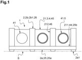
- the upper face 2b thus includes support strips 2b1, rectilinear, extending between the rectilinear grooves 21 and on which the users' feet will rest.
- the upper face 2b advantageously comprises an alternation of support strips 2b1 and rectilinear grooves 21.
- the rectilinear grooves 21 advantageously have a U-shaped section opening at the level of the upper face 2b of the floor mat 2.
- the rectilinear grooves 21 preferably comprise a bottom wall 211 (advantageously horizontal) delimited by two side walls 212 (advantageously vertical).
- the side walls 212 of a rectilinear groove 21 advantageously extend perpendicular to the bottom wall 211 and parallel to each other.
- the distance between two rectilinear grooves 21, corresponding to the width of a support strip 2b1, is for example 5 to 15 mm.
- the rectilinear grooves 21 advantageously extend parallel to the longitudinal edges 2c, opening at the level of the two transverse edges 2d.
- the floor mat 2 advantageously comprises a base 25 (advantageously horizontal) comprising several parallel partitions 26 (advantageously vertical).
- the base 25 advantageously has a height ranging from 3 to 15 mm.
- the base 25 preferably comprises at least one reinforcing layer (not shown).
- the reinforcing layer is chosen from textile fibers, metal or any other product providing stability and/or resistance to elongation.
- This reinforcing layer consists for example of a textile frame serving as reinforcement, advantageously made of a material chosen from nylon, cotton, polyester, polyamide or any other reinforcing textile.
- the lower face 2a of the floor mat 2 comprises projecting portions 2a1 forming legs (or pads), in order to allow the liquid to flow naturally; these projecting portions 2a1 also make it possible to maintain a space between the ground and the groundsheet 2, providing a thermal insulation role ( figure 1 ).
- These projecting portions 2a1 preferably have a maximum height ranging from 1 to 5 mm.
- the support strips 2b1, separating two rectilinear grooves 21, advantageously comprise staggered reliefs 2b2.
- the reliefs 2b2 are advantageously distributed staggered on the different support strips 2b1.
- the heating elements 3 are housed in the longitudinal grooves 21, advantageously extending into the thickness of the floor mat 2 (between its lower faces 2a and upper 2b) and advantageously without projecting above the upper face 2b of the carpet floor 2.
- the heating elements 3 are advantageously underlying with respect to the upper face 2b of the floor mat 2, for example by 1 to 5 mm.
- the upper face 2b of the floor mat 2 is advantageously offset relative to the heating elements 3, for example by 1 to 5 mm.
- the support strips 2b1 Preferably, between the reliefs 2b2, the support strips 2b1 have zero height relative to the heating members 3 to allow lateral water circulation favoring evacuation of liquid water.
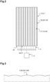
- the heating elements 3, including the metal profiles 4 and the plastic tubes 5, advantageously extend parallel to the longitudinal edges 2c of the floor mat 2 ( figure 2 ).
- the metal profile 4 consists for example of an elongated (solid) metal block in which the longitudinal conduit 41 is formed (also called “machined”).
- the metal profiles 4 advantageously have an elongated parallelepiped shape, complementary (within clearance) to the rectilinear grooves 21.
- the lower face 44, the upper face 45 and the two side faces 46 advantageously comprise reliefs cooperating with the side walls 212 of the rectilinear grooves 21, to participate in maintaining the metal profiles 4 within the rectilinear grooves 21.
- the upper face 45 of the metal profiles 4 advantageously extends at a distance from the upper face 2b of the floor mat 2, for example at a distance of 1 to 5 mm.
- the chosen metallic material advantageously has high thermal conductivity.
- the metal profile 4 is for example made of aluminum.
- the metal profiles 4 advantageously extend over the entire length of the rectilinear grooves 21 so as to end at the level of the two transverse edges 2d of the floor mat 2.
- the plastic tube 5 is for example made of polyethylene.
- the wall of the plastic tubes 5 has a thickness ranging from 0.5 to 2 mm.
- the longitudinal conduit 41 of the metal profile 4 and the plastic tube 5 are complementary, within clearance or with a maximum difference in diameter of 5 mm, preferably 0 to 2 mm.
- the external diameter of the plastic tube 5 is equal to or less than the diameter of the longitudinal conduit 41, preferably with a maximum difference in diameter of 5 mm, preferably 0 to 2 mm.
- the diameter of the longitudinal conduit 41 and the external diameter of the plastic tube 5 are advantageously 10 to 25 mm.
- the water temperature is adjusted to avoid freezing, for example from 10 to 30°C.
- the fluidic heating means 6 consist for example of a thermodynamic water heater, advantageously installed in a technical room, advantageously coupled to thermal solar collectors or to a geothermal heat source.
- tank we advantageously mean a reservoir or a tank intended to contain hot water, thermally insulated.
- heat pump we advantageously mean a device making it possible to transfer thermal energy (calories) from a low temperature medium (cold source) to a high temperature medium (hot source).
- the heat pump is chosen from water-water heat pumps: the thermal energy is transferred from a first heat transfer fluid intended to collect the thermal energy, to a second heat transfer fluid intended to restore the thermal energy to heat the water (stored here in the tank).
- the heating means 6 advantageously comprise control means intended to vary a temperature setpoint of the heat transfer fluid as a function of climatic conditions.
- the plastic tubes 5 are connected to the fluid heating means 6 in series and/or in parallel.
- the plastic tubes 5 of the parallel heating elements 3 are advantageously connected successively by junction tubes (not shown) which are advantageously embedded in a block of elastomeric material.
- the fluid heating means 6 When climatic conditions lead to a risk of freezing, the fluid heating means 6 generate a circulation of the heat transfer fluid along the plastic tubes 5.
- the heat from the heat transfer fluid then diffuses through the plastic tubes 5, to heat the metal profiles 4 and prevent the formation of a layer of gel.
- the structure of the heating covering 1 further contributes to optimal stability.
Landscapes
- Engineering & Computer Science (AREA)
- Architecture (AREA)
- Civil Engineering (AREA)
- Structural Engineering (AREA)
- Steam Or Hot-Water Central Heating Systems (AREA)
Claims (12)
- Beheizter Bodenbelag, der für den Außenbereich geeignet ist,
wobei der beheizte Bodenbelag- einen Bodenteppich (2), der aus einem Elastomermaterial gefertigt ist und der zwei voneinander abgewandte Seiten aufweist:-- eine Unterseite (2a), die dazu bestimmt ist, zum Boden hin gerichtet zu sein, und-- eine Oberseite (2b), an der geradlinige Hohlkehlen (21) münden, die parallel zueinander angeordnet sind,- in die geradlinigen Hohlkehlen (21) eingebrachte Heizorgane (3), die jeweils:-- ein geradliniges Metallprofil (4), in dem eine Längsleitung (41) eingerichtet ist, die in Höhe zweier voneinander abgewandter Enden (4d) des Metallprofils (4) austreten, und-- ein Plastikrohr (5), das in die Längsleitung (41) eingesetzt ist und in dem ein Wärmeträgerfluid fließen soll,
aufweisen,- Mittel für eine fluidische Heizung (6), die an die Plastikrohre (5) angeschlossen sind und die dazu ausgelegt sind, das Wärmeträgerfluid zu erwärmen und einen Kreislauf des Wärmeträgerfluids entlang der Plastikrohre (5) zu erzeugen,aufweist. - Beheizter Bodenbelag gemäß Anspruch 1, dadurch gekennzeichnet, daß die geradlinigen Hohlkehlen (21) einen in Höhe der Oberseite (2b) offenen U-förmigen Querschnitt haben,wobei die geradlinigen Hohlkehlen (21) eine von zwei Seitenwänden (212) begrenzte Bodenwand (211) aufweisen,und daß die Metallprofile (4) eine zu den geradlinigen Hohlkehlen (21) komplementäre längliche Quaderform aufweisen.
- Beheizter Bodenbelag gemäß einem der Ansprüche 1 oder 2, dadurch gekennzeichnet, daß die Längsleitung (41) des Metallprofils (4) und das Plastikrohr (5) bis aufs Spiel und mit einem maximalen Unterschied im Durchmesser von 5 mm komplementär sind.
- Beheizter Bodenbelag gemäß Anspruch 3, dadurch gekennzeichnet, daß der Durchmesser der Längsleitung (41) und der Außendurchmesser des Plastikrohrs (5) 10 bis 25 mm betragen.
- Beheizter Bodenbelag gemäß einem der Ansprüche 1 bis 4, dadurch gekennzeichnet, daß die geradlinigen Hohlkehlen (21)- eine Breite von 15 bis 50 mm und- eine Höhe von 15 bis 50 mmaufweisen.
- Beheizter Bodenbelag gemäß einem der Ansprüche 1 bis 5, dadurch gekennzeichnet, daß der Bodenteppich (2) einen rechteckigen Umfang aufweist, der durchzwei Längsränder (2c), die dessen Länge entsprechen, zum Beispiel von 1000 bis 2000 mm, undzwei Querränder (2d), die dessen Breite entsprechen, zum Beispiel von 1000 bis 1500 mm,begrenzt ist,
und daß sich die Heizorgane (3) vorteilhafterweise parallel zu den Längsrändern (2c) erstrecken. - Beheizter Bodenbelag gemäß einem der Ansprüche 1 bis 6, dadurch gekennzeichnet, daß der Bodenteppich (2) eine Basis (25) mit mehreren parallelen Trennwänden (26) aufweist,
wobei die Basis (25) zwei Oberflächen aufweist:- eine die Unterseite (2a) des Bodenteppichs (2) bildende untere Oberfläche (25a) und- eine obere Oberfläche (25b), von der aus sich die parallelen Trennwände (26) erstrecken, die die tragende Oberseite (2b) bilden und die geradlinigen Hohlkehlen (21) begrenzen. - Beheizter Bodenbelag gemäß Anspruch 7, dadurch gekennzeichnet, daß die Basis (25) mindestens eine Verstärkungsschicht aufweist.
- Beheizter Bodenbelag gemäß einem der Ansprüche 1 bis 8, dadurch gekennzeichnet, daß die Unterseite (2a) des Bodenteppichs (2) hervorstehende Abschnitte (2a1) aufweist, die Gestelle bilden.
- Beheizter Bodenbelag gemäß einem der Ansprüche 1 bis 9, dadurch gekennzeichnet, daß die Oberseite (2b) des Bodenteppichs (2) Auflagestreifen (2b1) bildet, die die geradlinigen Hohlkehlen (21) trennen, und daß die Auflagestreifen (2b1) gezackte Reliefs (2b2) aufweisen.
- Beheizter Bodenbelag gemäß einem der Ansprüche 1 bis 10, dadurch gekennzeichnet, daß die Plastikrohre (5) mit den Mitteln für eine fluidische Heizung (6) in Reihe und/oder parallel verbunden sind.
- Beheizter Bodenbelag gemäß einem der Ansprüche 1 bis 11, dadurch gekennzeichnet, daß die Heizmittel (6)- Mittel zum Erfassen, die dazu bestimmt sind, die Außentemperatur zu erfassen,- Rechenmittel zum Bestimmen einer Vorgabe für die Temperatur des Wärmeträgerfluids in Abhängigkeit von der Außentemperatur und- Mittel zum Einstellen des Betriebs der Heizmittel (6) in Abhängigkeit von der Vorgabe der Temperatur des Wärmeträgerfluidsaufweisen.
Applications Claiming Priority (1)
| Application Number | Priority Date | Filing Date | Title |
|---|---|---|---|
| FR2108476A FR3126009B1 (fr) | 2021-08-04 | 2021-08-04 | Revêtement chauffant pour le sol, adapté à un usage en extérieur |
Publications (3)
| Publication Number | Publication Date |
|---|---|
| EP4130388A1 EP4130388A1 (de) | 2023-02-08 |
| EP4130388B1 true EP4130388B1 (de) | 2024-07-31 |
| EP4130388C0 EP4130388C0 (de) | 2024-07-31 |
Family
ID=77711214
Family Applications (1)
| Application Number | Title | Priority Date | Filing Date |
|---|---|---|---|
| EP22188596.5A Active EP4130388B1 (de) | 2021-08-04 | 2022-08-03 | Beheizter bodenbelag, der für den aussenbereich geeignet ist |
Country Status (2)
| Country | Link |
|---|---|
| EP (1) | EP4130388B1 (de) |
| FR (1) | FR3126009B1 (de) |
Family Cites Families (5)
| Publication number | Priority date | Publication date | Assignee | Title |
|---|---|---|---|---|
| JPH08269908A (ja) * | 1995-03-29 | 1996-10-15 | Togawa Sangyo Kk | 融雪装置 |
| JPH09242037A (ja) * | 1996-03-13 | 1997-09-16 | Kajima Corp | 地面加熱システム |
| KR101027275B1 (ko) * | 2009-12-16 | 2011-04-06 | 이철호 | 탄소나노튜브 혼합물을 함유한 열전달물질을 이용한 제설용 발열체, 그 제조 장치 및 방법 |
| KR101898727B1 (ko) * | 2011-12-08 | 2018-09-14 | 재단법인 포항산업과학연구원 | 전열유닛을 이용한 도로 융설 장치 |
| US10533291B2 (en) * | 2015-01-13 | 2020-01-14 | Craig A. Perkins | Snow melting mat |
-
2021
- 2021-08-04 FR FR2108476A patent/FR3126009B1/fr active Active
-
2022
- 2022-08-03 EP EP22188596.5A patent/EP4130388B1/de active Active
Also Published As
| Publication number | Publication date |
|---|---|
| FR3126009B1 (fr) | 2024-05-24 |
| EP4130388A1 (de) | 2023-02-08 |
| FR3126009A1 (fr) | 2023-02-10 |
| EP4130388C0 (de) | 2024-07-31 |
Similar Documents
| Publication | Publication Date | Title |
|---|---|---|
| EP2366196A1 (de) | Einrichtung zum tragen von fotovoltaiczellenpanels, trägersystem und installierte baugruppe | |
| WO2009007606A2 (fr) | Echangeur vissé vertical enterré pour installation de chauffage ou de rafraichissement | |
| EP4130388B1 (de) | Beheizter bodenbelag, der für den aussenbereich geeignet ist | |
| WO2005042844A2 (fr) | Troncon modulaire de voie pour vehicule de transport urbain notamment autoguide sur pneumatiques | |
| NO820646L (no) | Varmeelement, saerlig som golv eller golvelement, og fremstillingsmaate for dette | |
| EP1460345A1 (de) | Bodenplatte mit Noppen zur Halterung von Heizungs- bzw. Kühlrohre | |
| EP2177684A2 (de) | Bauelement, sein Herstellungsverfahren und Umsetzungsverfahren einer Deckenheizung und/oder -kühlung | |
| KR101328024B1 (ko) | 도로 결빙 방지 장치 및 이를 포함하는 도로 포장체 | |
| FR2903429A1 (fr) | Ensemble autonettoyant par garnissage de lacune pour rail au sol de guidage ou de roulage. | |
| FR2997480A1 (fr) | Dispositif de chauffage d'eau avec fonction chauffage rapide. | |
| FR2952083A1 (fr) | Balcon destine a etre rapporte sur la facade d'un ouvrage et plus particulierement d'un batiment d'habitation et structure verticale supportant de tels balcons rapportes | |
| FR2940810A1 (fr) | Toiture avec protection d'etancheite. | |
| KR102013017B1 (ko) | 제빙용 롤을 구비한 제빙 차량 | |
| FR3035841A1 (fr) | Reservoir de liquide lave glace | |
| EP2697109A1 (de) | Verfahren zur montage von paneelen eines schwimmenden fussbodens | |
| EP1131585B1 (de) | Verfahren zu herstellung einer strassendecke mit wärmetransportelement | |
| FR2756232A1 (fr) | Tapis de sol chauffant pour vehicules | |
| CH170711A (fr) | Procédé de chauffage ou de refroidissement d'une surface d'échange et installation pour la mise en oeuvre de ce procédé. | |
| CA2851697A1 (en) | A snow melting mat system | |
| FR3009008A1 (fr) | Procede de realisation d'un plancher chauffant et/ou rafraichissant menage dans l'epaisseur d'un sol | |
| FR2480834A1 (fr) | Materiau pour le recouvrement de parois diverses | |
| FR3147302A1 (fr) | Dispositif d’arrêt de coulage d’un matériau de construction et procédé de rénovation d’un joint de dilatation ou d’un joint d’arrêt entre deux dalles | |
| KR102030378B1 (ko) | 발열모듈이 설치된 데크 구조물 | |
| EP2977696B1 (de) | System und verfahren zur steuerung der flüssigkondensate eines wärmetauschers | |
| EP1259770A1 (de) | Gleitbahnsegment |
Legal Events
| Date | Code | Title | Description |
|---|---|---|---|
| PUAI | Public reference made under article 153(3) epc to a published international application that has entered the european phase |
Free format text: ORIGINAL CODE: 0009012 |
|
| STAA | Information on the status of an ep patent application or granted ep patent |
Free format text: STATUS: THE APPLICATION HAS BEEN PUBLISHED |
|
| AK | Designated contracting states |
Kind code of ref document: A1 Designated state(s): AL AT BE BG CH CY CZ DE DK EE ES FI FR GB GR HR HU IE IS IT LI LT LU LV MC MK MT NL NO PL PT RO RS SE SI SK SM TR |
|
| P01 | Opt-out of the competence of the unified patent court (upc) registered |
Effective date: 20230526 |
|
| STAA | Information on the status of an ep patent application or granted ep patent |
Free format text: STATUS: REQUEST FOR EXAMINATION WAS MADE |
|
| 17P | Request for examination filed |
Effective date: 20230710 |
|
| RBV | Designated contracting states (corrected) |
Designated state(s): AL AT BE BG CH CY CZ DE DK EE ES FI FR GB GR HR HU IE IS IT LI LT LU LV MC MK MT NL NO PL PT RO RS SE SI SK SM TR |
|
| GRAP | Despatch of communication of intention to grant a patent |
Free format text: ORIGINAL CODE: EPIDOSNIGR1 |
|
| STAA | Information on the status of an ep patent application or granted ep patent |
Free format text: STATUS: GRANT OF PATENT IS INTENDED |
|
| INTG | Intention to grant announced |
Effective date: 20240328 |
|
| GRAS | Grant fee paid |
Free format text: ORIGINAL CODE: EPIDOSNIGR3 |
|
| GRAA | (expected) grant |
Free format text: ORIGINAL CODE: 0009210 |
|
| STAA | Information on the status of an ep patent application or granted ep patent |
Free format text: STATUS: THE PATENT HAS BEEN GRANTED |
|
| AK | Designated contracting states |
Kind code of ref document: B1 Designated state(s): AL AT BE BG CH CY CZ DE DK EE ES FI FR GB GR HR HU IE IS IT LI LT LU LV MC MK MT NL NO PL PT RO RS SE SI SK SM TR |
|
| RAP3 | Party data changed (applicant data changed or rights of an application transferred) |
Owner name: GROUP ELASTOTECK |
|
| REG | Reference to a national code |
Ref country code: CH Ref legal event code: EP Ref country code: GB Ref legal event code: FG4D Free format text: NOT ENGLISH |
|
| REG | Reference to a national code |
Ref country code: DE Ref legal event code: R096 Ref document number: 602022004932 Country of ref document: DE |
|
| REG | Reference to a national code |
Ref country code: IE Ref legal event code: FG4D Free format text: LANGUAGE OF EP DOCUMENT: FRENCH |
|
| U01 | Request for unitary effect filed |
Effective date: 20240829 |
|
| U07 | Unitary effect registered |
Designated state(s): AT BE BG DE DK EE FI FR IT LT LU LV MT NL PT RO SE SI Effective date: 20240909 |
|
| U20 | Renewal fee for the european patent with unitary effect paid |
Year of fee payment: 3 Effective date: 20240905 |
|
| P04 | Withdrawal of opt-out of the competence of the unified patent court (upc) registered |
Free format text: CASE NUMBER: APP_50298/2024 Effective date: 20240904 |
|
| P05 | Withdrawal of opt-out of the competence of the unified patent court (upc) changed |
Free format text: CASE NUMBER: APP_50298/2024 Effective date: 20240909 |
|
| PG25 | Lapsed in a contracting state [announced via postgrant information from national office to epo] |
Ref country code: NO Free format text: LAPSE BECAUSE OF FAILURE TO SUBMIT A TRANSLATION OF THE DESCRIPTION OR TO PAY THE FEE WITHIN THE PRESCRIBED TIME-LIMIT Effective date: 20241031 |
|
| PG25 | Lapsed in a contracting state [announced via postgrant information from national office to epo] |
Ref country code: GR Free format text: LAPSE BECAUSE OF FAILURE TO SUBMIT A TRANSLATION OF THE DESCRIPTION OR TO PAY THE FEE WITHIN THE PRESCRIBED TIME-LIMIT Effective date: 20241101 Ref country code: PL Free format text: LAPSE BECAUSE OF FAILURE TO SUBMIT A TRANSLATION OF THE DESCRIPTION OR TO PAY THE FEE WITHIN THE PRESCRIBED TIME-LIMIT Effective date: 20240731 |
|
| PG25 | Lapsed in a contracting state [announced via postgrant information from national office to epo] |
Ref country code: IS Free format text: LAPSE BECAUSE OF FAILURE TO SUBMIT A TRANSLATION OF THE DESCRIPTION OR TO PAY THE FEE WITHIN THE PRESCRIBED TIME-LIMIT Effective date: 20241130 |
|
| PG25 | Lapsed in a contracting state [announced via postgrant information from national office to epo] |
Ref country code: HR Free format text: LAPSE BECAUSE OF FAILURE TO SUBMIT A TRANSLATION OF THE DESCRIPTION OR TO PAY THE FEE WITHIN THE PRESCRIBED TIME-LIMIT Effective date: 20240731 |
|
| PG25 | Lapsed in a contracting state [announced via postgrant information from national office to epo] |
Ref country code: ES Free format text: LAPSE BECAUSE OF FAILURE TO SUBMIT A TRANSLATION OF THE DESCRIPTION OR TO PAY THE FEE WITHIN THE PRESCRIBED TIME-LIMIT Effective date: 20240731 Ref country code: RS Free format text: LAPSE BECAUSE OF FAILURE TO SUBMIT A TRANSLATION OF THE DESCRIPTION OR TO PAY THE FEE WITHIN THE PRESCRIBED TIME-LIMIT Effective date: 20241031 |
|
| PG25 | Lapsed in a contracting state [announced via postgrant information from national office to epo] |
Ref country code: RS Free format text: LAPSE BECAUSE OF FAILURE TO SUBMIT A TRANSLATION OF THE DESCRIPTION OR TO PAY THE FEE WITHIN THE PRESCRIBED TIME-LIMIT Effective date: 20241031 Ref country code: PL Free format text: LAPSE BECAUSE OF FAILURE TO SUBMIT A TRANSLATION OF THE DESCRIPTION OR TO PAY THE FEE WITHIN THE PRESCRIBED TIME-LIMIT Effective date: 20240731 Ref country code: NO Free format text: LAPSE BECAUSE OF FAILURE TO SUBMIT A TRANSLATION OF THE DESCRIPTION OR TO PAY THE FEE WITHIN THE PRESCRIBED TIME-LIMIT Effective date: 20241031 Ref country code: IS Free format text: LAPSE BECAUSE OF FAILURE TO SUBMIT A TRANSLATION OF THE DESCRIPTION OR TO PAY THE FEE WITHIN THE PRESCRIBED TIME-LIMIT Effective date: 20241130 Ref country code: HR Free format text: LAPSE BECAUSE OF FAILURE TO SUBMIT A TRANSLATION OF THE DESCRIPTION OR TO PAY THE FEE WITHIN THE PRESCRIBED TIME-LIMIT Effective date: 20240731 Ref country code: GR Free format text: LAPSE BECAUSE OF FAILURE TO SUBMIT A TRANSLATION OF THE DESCRIPTION OR TO PAY THE FEE WITHIN THE PRESCRIBED TIME-LIMIT Effective date: 20241101 Ref country code: ES Free format text: LAPSE BECAUSE OF FAILURE TO SUBMIT A TRANSLATION OF THE DESCRIPTION OR TO PAY THE FEE WITHIN THE PRESCRIBED TIME-LIMIT Effective date: 20240731 |
|
| PG25 | Lapsed in a contracting state [announced via postgrant information from national office to epo] |
Ref country code: SM Free format text: LAPSE BECAUSE OF FAILURE TO SUBMIT A TRANSLATION OF THE DESCRIPTION OR TO PAY THE FEE WITHIN THE PRESCRIBED TIME-LIMIT Effective date: 20240731 |
|
| PG25 | Lapsed in a contracting state [announced via postgrant information from national office to epo] |
Ref country code: MC Free format text: LAPSE BECAUSE OF FAILURE TO SUBMIT A TRANSLATION OF THE DESCRIPTION OR TO PAY THE FEE WITHIN THE PRESCRIBED TIME-LIMIT Effective date: 20240731 |
|
| PG25 | Lapsed in a contracting state [announced via postgrant information from national office to epo] |
Ref country code: CZ Free format text: LAPSE BECAUSE OF FAILURE TO SUBMIT A TRANSLATION OF THE DESCRIPTION OR TO PAY THE FEE WITHIN THE PRESCRIBED TIME-LIMIT Effective date: 20240731 |
|
| PG25 | Lapsed in a contracting state [announced via postgrant information from national office to epo] |
Ref country code: SK Free format text: LAPSE BECAUSE OF FAILURE TO SUBMIT A TRANSLATION OF THE DESCRIPTION OR TO PAY THE FEE WITHIN THE PRESCRIBED TIME-LIMIT Effective date: 20240731 |
|
| PLBE | No opposition filed within time limit |
Free format text: ORIGINAL CODE: 0009261 |
|
| STAA | Information on the status of an ep patent application or granted ep patent |
Free format text: STATUS: NO OPPOSITION FILED WITHIN TIME LIMIT |
|
| 26N | No opposition filed |
Effective date: 20250501 |
|
| U20 | Renewal fee for the european patent with unitary effect paid |
Year of fee payment: 4 Effective date: 20250618 |
|
| PG25 | Lapsed in a contracting state [announced via postgrant information from national office to epo] |
Ref country code: IE Free format text: LAPSE BECAUSE OF NON-PAYMENT OF DUE FEES Effective date: 20240803 |
|
| PG25 | Lapsed in a contracting state [announced via postgrant information from national office to epo] |
Ref country code: CY Free format text: LAPSE BECAUSE OF FAILURE TO SUBMIT A TRANSLATION OF THE DESCRIPTION OR TO PAY THE FEE WITHIN THE PRESCRIBED TIME-LIMIT; INVALID AB INITIO Effective date: 20220803 |
|
| PG25 | Lapsed in a contracting state [announced via postgrant information from national office to epo] |
Ref country code: HU Free format text: LAPSE BECAUSE OF FAILURE TO SUBMIT A TRANSLATION OF THE DESCRIPTION OR TO PAY THE FEE WITHIN THE PRESCRIBED TIME-LIMIT; INVALID AB INITIO Effective date: 20220803 |
|
| REG | Reference to a national code |
Ref country code: CH Ref legal event code: H13 Free format text: ST27 STATUS EVENT CODE: U-0-0-H10-H13 (AS PROVIDED BY THE NATIONAL OFFICE) Effective date: 20260324 |
|
| PG25 | Lapsed in a contracting state [announced via postgrant information from national office to epo] |
Ref country code: CH Free format text: LAPSE BECAUSE OF NON-PAYMENT OF DUE FEES Effective date: 20250831 |