EP4130366B1 - Machine textile pour la fabrication de tissus textiles et dispositif de guidage de fils - Google Patents
Machine textile pour la fabrication de tissus textiles et dispositif de guidage de fils Download PDFInfo
- Publication number
- EP4130366B1 EP4130366B1 EP22207539.2A EP22207539A EP4130366B1 EP 4130366 B1 EP4130366 B1 EP 4130366B1 EP 22207539 A EP22207539 A EP 22207539A EP 4130366 B1 EP4130366 B1 EP 4130366B1
- Authority
- EP
- European Patent Office
- Prior art keywords
- force
- textile
- thread
- deformation
- displacement
- Prior art date
- Legal status (The legal status is an assumption and is not a legal conclusion. Google has not performed a legal analysis and makes no representation as to the accuracy of the status listed.)
- Active
Links
Images


Classifications
-
- B—PERFORMING OPERATIONS; TRANSPORTING
- B65—CONVEYING; PACKING; STORING; HANDLING THIN OR FILAMENTARY MATERIAL
- B65H—HANDLING THIN OR FILAMENTARY MATERIAL, e.g. SHEETS, WEBS, CABLES
- B65H59/00—Adjusting or controlling tension in filamentary material, e.g. for preventing snarling; Applications of tension indicators
- B65H59/10—Adjusting or controlling tension in filamentary material, e.g. for preventing snarling; Applications of tension indicators by devices acting on running material and not associated with supply or take-up devices
-
- D—TEXTILES; PAPER
- D04—BRAIDING; LACE-MAKING; KNITTING; TRIMMINGS; NON-WOVEN FABRICS
- D04B—KNITTING
- D04B27/00—Details of, or auxiliary devices incorporated in, warp knitting machines, restricted to machines of this kind
- D04B27/10—Devices for supplying, feeding, or guiding threads to needles
- D04B27/12—Tensioning devices for individual threads
-
- B—PERFORMING OPERATIONS; TRANSPORTING
- B65—CONVEYING; PACKING; STORING; HANDLING THIN OR FILAMENTARY MATERIAL
- B65H—HANDLING THIN OR FILAMENTARY MATERIAL, e.g. SHEETS, WEBS, CABLES
- B65H59/00—Adjusting or controlling tension in filamentary material, e.g. for preventing snarling; Applications of tension indicators
- B65H59/10—Adjusting or controlling tension in filamentary material, e.g. for preventing snarling; Applications of tension indicators by devices acting on running material and not associated with supply or take-up devices
- B65H59/20—Co-operating surfaces mounted for relative movement
- B65H59/26—Co-operating surfaces mounted for relative movement and arranged to deflect material from straight path
-
- B—PERFORMING OPERATIONS; TRANSPORTING
- B65—CONVEYING; PACKING; STORING; HANDLING THIN OR FILAMENTARY MATERIAL
- B65H—HANDLING THIN OR FILAMENTARY MATERIAL, e.g. SHEETS, WEBS, CABLES
- B65H59/00—Adjusting or controlling tension in filamentary material, e.g. for preventing snarling; Applications of tension indicators
- B65H59/10—Adjusting or controlling tension in filamentary material, e.g. for preventing snarling; Applications of tension indicators by devices acting on running material and not associated with supply or take-up devices
- B65H59/36—Floating elements compensating for irregularities in supply or take-up of material
-
- D—TEXTILES; PAPER
- D04—BRAIDING; LACE-MAKING; KNITTING; TRIMMINGS; NON-WOVEN FABRICS
- D04B—KNITTING
- D04B27/00—Details of, or auxiliary devices incorporated in, warp knitting machines, restricted to machines of this kind
- D04B27/10—Devices for supplying, feeding, or guiding threads to needles
- D04B27/14—Thread tensioning rod arrangements
-
- B—PERFORMING OPERATIONS; TRANSPORTING
- B65—CONVEYING; PACKING; STORING; HANDLING THIN OR FILAMENTARY MATERIAL
- B65H—HANDLING THIN OR FILAMENTARY MATERIAL, e.g. SHEETS, WEBS, CABLES
- B65H2701/00—Handled material; Storage means
- B65H2701/30—Handled filamentary material
- B65H2701/31—Textiles threads or artificial strands of filaments
Definitions
- the present invention relates to a textile machine for producing textile fabrics and a thread guiding device for use on a textile machine.
- processing on a weaving machine is carried out by weaving the textile threads at right angles, which run alternately over and under each other, whereas processing on a warp knitting machine is carried out by forming stitches.
- the individual textile threads are fed to the working area, in particular to the thread-guiding processing elements arranged therein, whereby it must be ensured that the individual textile threads are guided into the working area during processing by the textile machine in a continuous, reliable, precisely positioned manner and without mutual obstruction, for example by tangling.
- thread guide devices are used which redirect a textile thread from the thread storage device into the work area under tension, for example via a deflection roller or the like.
- the element of the thread guide device in contact with the textile thread is movably mounted in order to provide variable deflection, in which the feed of the textile thread adapts accordingly to the relative movement of the processing element receiving the textile thread in the work area. In this way, a short-term increase in the need for textile thread to be fed or a short-term decrease in the need for textile thread to be fed can be compensated.
- the thread guide device not only fulfils the function of variable deflection described above, but also acts as a thread tensioner, which exerts a tensioning force on the textile thread guided through the thread guide device in order to tension it and thus be able to guide it better than in an untensioned state.
- Such a thread guide device is known, for example, from US 3 631 689 A which discloses a warp knitting machine with a tensioning device for textile threads, in which the textile threads run over a deflection section which is arranged at a tip of a thin, deformable sheet metal bending spring which exerts a tensioning force on the guided textile thread
- this combined functionality of variable deflection and tensioning of the textile thread leads, as in the case of US 3 631 689 A , to a varying tension force acting on the textile thread during processing, as a result of which a thread tension in the textile thread also varies.
- a to the one from the US 3 631 689 A A similar structure of a thread guide is also known from the DE 20 2019 105 145 U1 known, in which a bending or leaf spring is also used to guide a textile thread.
- EP 2 143 681 A1 a thread deflection unit of a winding machine for winding a spool material on a winding spindle is known, which also uses a leaf spring to tension the spool material.
- An object of the present invention is to provide an improved possibility for the automated production of a textile fabric with high product quality.
- a thread guide device for a textile machine according to claim 1 and a textile machine according to claim 13 are provided.
- the thread guide device in turn comprises at least one deflection element which deflects a textile thread in contact with it from the textile thread storage into the working area, wherein the deflection element is movably mounted relative to the textile thread storage in a displacement area between a first and a second end position, and a tensioning device which supports the deflection element and which exerts a tensioning force on the textile thread in contact with the deflection element and for this purpose comprises a force element which can be deformed by displacing the deflection element.
- the force element comprises at least one first elastic spring element which is deformed by a displacement of a displacement point of the first spring element along a displacement direction which is dependent on the displacement of the deflection element, wherein the first spring element is a Spring element with a degressive force-deformation relationship or a constant force spring.
- a ratio of a deformation force of the force element averaged over the displacement range of the deflection element to the deformation force of the force element in the first or second end position of the deflection element is 0.8 to 1.2.
- the ratio of the average deformation force and the force at one of the end positions is also referred to as the "force ratio" below.
- textile fabric refers to any two-dimensional textile product, regardless of the manufacturing process used. Examples include woven fabrics, knitwear, felt, carpets, tufted carpets, nonwovens, bobbins, nets, braids, multi-textiles or stitch-knitted goods.
- the processing of the textile thread is carried out by a large number of processing elements of the textile machine arranged in the working area (in the case of a knitting machine, for example, by knitting elements such as eyelet and slide needles), which move relative to one another in the working area in order to link, weave, knit or the like a large number of textile threads together.
- the textile threads are unwound from the textile thread storage, which is usually designed as a warp beam, and guided via the deflection element into the working area, where they are either received directly by the processing elements or initially guided into the work area via additional deflection elements.
- the deflection element can be designed, for example, as a rotatable or non-rotatable deflection, or even just a curved guide section, over the surface of which the textile thread runs from the textile thread storage into the working area.
- the thread guide device is not limited to use with just one textile thread, but is preferably designed in such a way that a large number of textile threads are guided parallel to one another from the textile thread storage via the deflection element into the working area.
- the tensioning force exerted on one or more textile threads is not zero in the event of contact with the deflection element during processing with the deflection element located within the displacement range and is provided by the deformation force of the force element of the tensioning device, which is dependent on the displacement of the deflection element.
- the force element is understood to mean any element that can be deformed under the influence of force, for example mechanical springs and the like.
- Elastic spring elements are elastic solid elements that are geometrically designed as elastically deformable elements according to their use, such as leaf springs, disc springs, coil springs and the like.
- the direction of displacement can be straight, curved or angular, depending on the type of spring element used.
- the displacement point represents the interface to the deflection element, whereby any type of connecting means or a transmission mechanism can be arranged in between.
- the spring element with a degressive force-deformation relationship advantageously has smaller changes in the deformation force in the deformation range with changing deformation. Furthermore, the constant force spring delivers an essentially constant deformation force across the deformation range.
- the displacement of the deflection element is transferred directly or via a translation mechanism to the force element and leads to the deformation of the same, whereby the area between the deformation when the deflection element is in the first end position and the deformation when the deflection element is in the second end position is hereinafter referred to as the deformation area of the force element, which is connected to the displacement area either directly or via the translation mechanism.
- the required force ratio thus defines a force-deformation relation of the force element in the displacement range of the deflection element, in which the averaged deformation force in relation to the deformation force at one of the two end positions deviates from this by a maximum of 20%.
- the deformation force of the force element is transferred to the deflection element connected to it (directly or via transmission mechanics) and provides the tension force, which is transferred via the deflection element to the textile thread or threads in contact with it and causes a build-up of thread tension in the textile thread or threads, so that it is guided under tension from the thread storage into the working area.
- the tensioning force is to be understood as the force provided by the tensioning device, which corresponds to a contact force between the textile thread and the deflection element, whereby in the case of a large number of textile threads the tensioning force corresponds to the sum of the respective contact forces for the large number of contacts of the individual textile threads with the deflection element.
- the tension force can correspond to the deformation force (directly) or is related to it via a transmission ratio of the transmission mechanics.
- the requirement for the force ratio ensures that the variation in the deformation force of the force element and thus also in the tensioning force applied by the tensioning device is small across the displacement range of the deflection element, so that any resulting variation in the thread tension in the textile thread is largely prevented.
- the textile thread is deformed evenly during processing, in particular the textile thread is stretched evenly in the thread direction, so that a textile fabric with high product quality can be manufactured.
- the textile machine according to the invention provides a particularly advantageous possibility for thread diversion into the working area, in which the functionalities of a variable diversion to compensate for an excess or a decrease in the demand for the textile thread and a tensioning of the textile thread to be guided into the working area are combined in such a way that a variable supply of the textile thread via the deflection element takes place under tension with a slightly varying tension force, which leads to a correspondingly small variation in the thread tension in the textile thread.
- the force element is deformed to provide the clamping force, for example in the form of an end point displacement of the force element.
- the deformation range of the force element preferably extends from a deformed first state to a more strongly deformed second state of the force element, so that a clamping force can be applied at any point in the displacement range.
- the deformation range preferably does not include an undeformed state of the force element with a deformation force equal to zero, wherein no or only very slight plastic deformation of the force element should occur in the deformation range.
- a force element is used in the tensioning device which, starting from the first and/or second end position, provides a corresponding minimum tensioning force for tensioning the textile thread through its deformation force, which, moreover, does not change or only changes slightly over the deformation range.
- an elastic solid element for example a mechanical spring
- a force-deformation relationship that is linear in the displacement area is unsuitable for use according to the invention, since it cannot meet the above requirements for the force ratio in the displacement area.
- the US 3 631 689 A The sheet metal spring shown is unsuitable.
- elastic solid-state elements which, for example, have a degressive force-deformation relationship, thereby providing a small variation in the deformation force while at the same time maintaining the minimum tension force for tensioning the textile thread.
- the force ratio includes the deformation force of the force element averaged over the displacement range of the deflection element, which should be understood as any mean value of the deformation force of the force element, which is usually dependent on deformation, over the displacement range.
- the said mean value is also referred to below with the formula symbol M, which can optionally be used with an additional index.
- the force ratio f 1,2 can be specified on the basis of the mean value M and on the basis of the deformation force F 1 of the force element at the first end position or the deformation force F 2 of the force element at the second end position according to equation 1 or equation 2, respectively.
- f 1 M F 1 ⁇ 0 ,8 ,1 ,2
- f 2 M F 2 ⁇ 0 ,8 , 1 ,2
- the choice of the underlying force ratio i.e. f 1 with deformation force at the first end position or f 2 with deformation force at the second end position, is arbitrary and is preferably selected such that the end position for forming the ratio is selected in which the deflection element is located for a longer period of time during operation of the textile machine for producing a textile fabric.
- Said mean value M is a measure of the deformation force present in the means for generating the tension force over the displacement range of the deflection element or over the deformation range determined thereby and can, for example, be an integral mean value M int (see equation 3), a discretely evaluated arithmetic mean value, or the like.
- M int 1 x 2 ⁇ x 1 ⁇ x 1 x 2 F dx
- F denotes the deformation force of the force element, which depends on the displacement x of the deflection element, where x 1 and x 2 denote the first and second end positions respectively.
- the displacement x does not necessarily have to correspond to the deformation of the force element, since any type of transmission mechanism can be arranged between the deflection element and the force element. In this case, the displacement of the deflection element could be converted into a corresponding deformation using a known transmission ratio.
- the displacement of the deflection element should not be limited to a translational displacement or a linear displacement.
- the deflection element can not only be mounted so that it can be displaced in a linear manner, but also so that it can rotate around a corresponding bearing point, for example, whereby a displacement in this case can be described by an angle.
- the x used in the previous equation 3 can thus be understood equally as a linear, curvilinear or angular displacement.
- the requirement of a maximum deviation of 20% applies both to the force ratio in relation to the deformation force at the first end position and to the force ratio in relation to the deformation force at the second end position.
- the clamping device should satisfy both requirements according to equations 1 and 2.
- the ratio of the deformation force of the force element averaged over the displacement range of the deflection element to the deformation force of the force element in the first or in the second end position of the deflection element 0.9 to 1.1, more preferably 0.95 to 1.05 and particularly preferably 1, whereby said variations in the tension force are increasingly reduced.
- the textile machine comprises a plurality of substantially identically constructed thread guide devices, each of which is designed to guide a separate textile thread or a plurality of parallel textile threads.
- the force element is designed such that a ratio of a maximum deformation force of the force element occurring over the displacement range of the deflection element to a minimum deformation force of the force element occurring over the displacement range of the deflection element is 1 to 1.2.
- the ratio of the maximum deformation force of the force element occurring over the displacement range of the deflection element to a minimum deformation force of the force element occurring over the displacement range of the deflection element is 1 to 1.1, more preferably 1 to 1.05 and particularly preferably 1, whereby said local deviations in the tension force are increasingly reduced.
- the force element of the tensioning device is designed such that an amount of a rate of change of the deformation force of the force element averaged over the displacement range of the deflection element is less than or equal to 1,500 N/m (Newtons per meter; or 1.5 N/mm).
- a requirement for the derivation of the force-deformation relation of the force element in averaged form is formulated, whereby the derivation in the mechanical In this sense, it can be understood, for example, as the stiffness of the force element.
- the aforementioned requirement for the rate of change ensures that, on average, the rate of change of the tension force based on it also remains within specified limits.
- Said mean value is also abbreviated below with the symbol m and is a measure of the mean changes in the deformation force present to generate the clamping force over the displacement range and can, for example, be an integral mean value m int (see equation 5), a discretely evaluated arithmetic mean value, or the like.
- m int 1 x 2 ⁇ x 1 ⁇ x 1 x 2 dF dx dx
- the amount of the rate of change of the deformation force of the force element averaged over the displacement range of the deflection element is less than or equal to 1,000 N/m or 1.0 N/mm, more preferably less than or equal to 500 N/m or 0.5 N/mm, even more preferably less than or equal to 100 N/m or 0.1 N/mm and particularly preferably 0 N/m or 0 N/mm, whereby variations in the rate of change of the tension force are increasingly reduced.
- the amount of the extreme (minimal and/or maximum) rate of change of the deformation force of the force element over the displacement range of the deflection element is less than or equal to 1,500 N/m or 1.5 N/mm, more preferably less than or equal to 1,000 N/m or 1.0 N/mm, more preferably less than or equal to 500 N/m or 0.5 N/mm, more preferably less than or equal to 100 N/m or 0.1 N/mm and particularly preferably 0 N/m or 0 N/mm.
- the force element of the tensioning device is designed such that its deformation force is constant over the displacement range of the deflection element
- the force element of the tensioning device is designed in such a way that the tensioning force exerted on the textile thread in contact with the deflection element or the tensioning force exerted on the textile threads for the Displacement range of the deflection element causes a thread force in the textile thread or threads of 0 to 1 Newton.
- Thread force is the normal force (tensile force) acting in the thread direction in a cutting plane perpendicular to the thread direction, which describes the resulting force of the thread tension normal to the cutting plane
- the force element is designed such that the tensioning force exerted on the textile thread in contact with the deflection element for the displacement range of the deflection element causes a thread force in the textile thread of 0 to 0.4 Newton and particularly preferably of 0 to 0.2 Newton.
- the force element comprises a second elastic spring element which can be arranged in series or parallel to the first spring element with respect to a displacement of the deflection element.
- the second elastic spring element is arranged relative to the first spring element such that, by displacement of the deflection element, the first spring element is compressed and the second spring element is expanded or the first spring element is expanded and the second spring element is compressed.
- the above arrangement of the first and the second spring element results in the deformation force of the force element, which is used to generate the tensioning force for tensioning the textile thread, being based on a difference between the deformation force of the first and the deformation force of the second spring element.
- a deformation force of the force element of 0.5 Newton can be provided as the difference between the exemplary deformation forces of 10 Newton and 9.5 Newton of the first and second spring elements, respectively.
- the second elastic spring element is arranged relative to the first spring element such that the first and second spring elements are jointly compressed or expanded by displacement of the deflection element.
- a thread guiding device for a plurality of textile threads in which the deflection element partially extends over a width of the working area in such a way that it deflects a plurality of textile threads distributed over the width of the working area from the textile thread storage into the working area.
- the above arrangement of the first and the second spring element can be used, which allows an additive superposition of individual deformation forces of the spring elements to provide a higher deformation force for the plurality of textile threads to be guided.
- the tensioning device comprises a plurality of elastic spring elements which are jointly compressed or expanded by displacement of the deflection element.
- the tensioning device further comprises an adjustment element via which an initial deformation state of the force element can be set when no textile thread is in contact with the deflection element.
- a desired pre-deformation can be set so that, over the displacement range of the deflection element, the deformation range lies in a desired range of the force-deformation relation of the force element or the first spring element or the "resulting" force-deformation relation of the first and second spring elements.
- the adjusting element is designed as an adjustable stop for the force element, in particular as a stop for a bearing point of the force element located at the displacement point of the first spring element.
- At least the first elastic spring element of the force element is designed as an elastic bending beam, which, over the displacement range of the deflection element, has an elastic pre-deformation in the form of a Deflection in a bending direction that is at an angle to the direction of displacement of the displacement point of the first spring element and undergoes a change in deflection by moving the displacement point of the first spring element.
- a particularly easy-to-implement and cost-effective concept of a constant force spring which has a substantially constant deformation force over a corresponding deformation range, on which the tensioning force for tensioning the textile thread is based.
- the deformation force is understood to be the reaction force of the force element acting on the displacement point in the direction of displacement.
- Such spring elements can also be referred to as initially deformed buckling rods, which, starting from an already existing Eulerian buckling case, have a deformation range with an essentially constant deformation force.
- all elastic spring elements of the force element are designed as elastic bending beams according to the above embodiment.
- a longitudinal extension of at least one elastic bending beam of a force element along a center line is greater than cross-sectional extensions of the elastic bending beam in a cross section perpendicular to the center line, wherein a cross-sectional extension along the bending direction is smaller than a cross-sectional extension along a direction orthogonal to the bending direction.
- all elastic bending beams of the force element satisfy the above geometric requirements.
- the elastic bending beam has a rectangular cross-sectional shape in said cross-section, thereby providing a particularly cost-effective design of the bending beam.
- the transmission ratio of the transmission mechanism is matched to a force-deformation relationship of the force element in such a way that the tension force exerted on the textile thread in contact with the deflection element causes a constant thread force in the textile thread for the displacement range of the deflection element.
- the textile machine is a warp knitting machine in which the working area is a knitting area in which the textile fabric is manufactured as a knitted fabric.
- a thread guiding device of a textile machine according to the first aspect of the invention is provided.
- the thread guide device designed for use on a textile machine according to the first aspect can be designed according to one of the embodiments described in the context of the textile machine according to the invention.
- orthogonal, right-handed coordinate systems ⁇ x,y,z ⁇ are used as examples, in which the first two directions, x-direction and y-direction, are each in the drawing plane and the third direction, z-direction, points orthogonally out of the drawing plane (dot notation) or into the drawing plane (cross notation).
- the direction specifications used below in the form "in the x-direction” or “in the y-direction” for kinematic quantities such as deformations, displacements and the like are not intended to restrict said quantities to the "positive" direction introduced by the arrow direction, unless otherwise stated, but also to include the opposite "negative" direction.
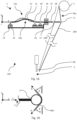
- Fig. 1A shows a schematic view of a section of a first embodiment of the textile machine 100 according to the invention.
- the textile machine comprises a textile thread storage 1 for providing a textile thread 200, a working area 3 in which the textile thread 200 together with other, here textile threads not shown are processed, and a thread guide device 2 which guides the textile thread 200 from the textile thread storage 1 into the working area 3.
- the processing of the textile threads 200 is carried out by processing elements 99 arranged in the working area, of which only one is shown as an example in Fig. 1A is shown.
- the textile thread 200 coming from the textile thread storage 1 is fed to the processing element 99 in the working area 3.
- the thread guide device 2 is designed to variably redirect the textile thread 200 into the working area 3 in order to compensate for an excess or shortfall in the need for textile thread 200 during processing. At the same time, the textile thread 200 redirected by the thread guide device 2 is tensioned with a tensioning force
- the thread guide device 2 comprises a deflection element 11 which deflects a textile thread 200 in contact with it from the textile thread storage 1 into the working area 3, wherein the deflection element 11 is movably mounted relative to the textile thread storage 1 in a displacement range between a first and a second end position in the x-direction shown, a tensioning device 13a which supports the deflection element 11 and exerts a tensioning force on the textile thread 200 in contact with the deflection element 11, and a carrier body 12, indicated schematically here, on which the tensioning device 13a is fastened and which can be mounted on a machine frame of the textile machine 100 (not shown here).
- the tensioning device 13a can alternatively also be mounted directly on the machine frame without a carrier body 12.
- the end positions of the displacement range are in Fig. 1A (as well as in the Fig. 2 to 4 ) is represented by two separate representations: a representation based on solid lines for the first end position and a representation based on dashed lines for the second end position.
- the configuration in the second end position is characterized by a dash notation of the respective reference symbols, for example 200' for the textile thread in the second end position of the deflection element 11'.
- the tensioning device 13a which exerts a tensioning force on the textile thread 200 in contact with the deflection element 11, comprises a force element 30a that can be deformed by moving the deflection element 11 for providing the tensioning force on the basis of a deformation force of the force element 30a.
- the force element 30a comprises a constant force spring 31, which is connected to the deflection element 11 via a direct transmission 36a.
- the force element 30a further comprises a fixed-loose bearing for the constant force spring 31, which comprises a fixed bearing 33 and a loose bearing 34 that is movable along the x-direction shown. The displacement of the deflection element in x-direction is transferred to the movable bearing 34 and thus leads to a deformation of the constant force spring 31.
- a force-deformation relation of the force element 30a is determined in the present case by a force-deformation relation of the constant force spring 31, which itself has a deformation force that is essentially constant over the displacement range of the deflection element 11 (see also Fig. 7 ), so that the textile thread 200 in contact with the deflection element 11 is tensioned by a tension force that does not vary as much as possible.
- the constant force spring 31 is designed as an elastic bending beam, which has an elastic pre-deformation in the form of a deflection in a bending direction (y-direction) at an angle to the direction of displacement (x-direction) of the movable floating bearing 34 (in particular at right angles to the direction of displacement) over the displacement range of the deflection element 11 and experiences a change in the deflection by moving the movable floating bearing 34 (see 31, 31').
- Such a mechanical design is simple and inexpensive to implement and enables, for example, the implementation of the Fig. 7 shown force-deformation relation.
- the direct transmission 36a between the force element 30a and the deflection element 11 comprises a connecting element 38 arranged between the movable bearing 34 and the deflection element 11, which is movably mounted in the x-direction shown via a bearing 37.
- a connecting element 38 arranged between the movable bearing 34 and the deflection element 11, which is movably mounted in the x-direction shown via a bearing 37.
- the clamping device 13a comprises a stop element 35 for the movable floating bearing 34 of the force element 30a, with which a pre-deformation of the force element 30a can be set or ensured.
- the stop element 35 can be arranged in a fixed position in relation to the fixed bearing 33 of the force element 30a.
- the stop element 35 can also be designed to be displaceable in its position relative to the fixed bearing 33 in order to be able to set a pre-deformation of the force element 30a quickly and without major structural changes (not shown here).
- Fig. 1B shows a cutout on the deflection element 11 of the thread guide device 2 from the first embodiment of the textile machine 100 from Fig. 1A .
- the clamping device 13a acts Fig. 1A the force components F Sx and F Sy on the deflection element, which are ultimately in equilibrium with the thread force N (normal force in the textile thread 200).
- the horizontal component F Sx of the tensioning force is determined by the deformation force of the force element 30a of the tensioning device 13a from Fig. 1A , whereas the vertical component F Sy results as a bearing reaction from the bearing 37 of the connecting element. Friction effects between the textile thread and the deflection element 11 are neglected and a static state is assumed as an example.
- An entry angle ⁇ of the textile thread 200 into the deflection element 11 corresponds, in simplified and non-restrictive terms, to an exit angle ⁇ of the textile thread 200 from the deflection element 11 into the working area.
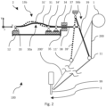
- Fig. 2 shows a schematic view of a section of a second embodiment of the textile machine 100 according to the invention.
- the basic structure of the textile machine 100 according to the second embodiment corresponds to that of the first embodiment of Fig. 1A , whereby a different embodiment of the clamping device 13b is used, which differs only in the connection between the force element 30a and the deflection element 11.
- a further description of the Fig. 1A Analogue components are therefore omitted.
- the clamping device 13b comprises a transmission mechanism 36b, which comprises a rotatably mounted transmission element 39, at the end of which the deflection element 11 is attached and which is connected to the force element 30a via a connecting element 38 which is movably mounted in the x-direction.
- the translation element 39 serves as a lever arm, via which the deformation force acting in the x-direction through the force element 30a can be translated according to the well-known lever law, so that, for example, the tension force acting on the textile thread is greater or smaller than the deformation force
- Fig. 3 shows a schematic view of a section of a third embodiment of the textile machine 100 according to the invention.
- the textile machine 100 comprises, as in the case of the first two embodiments, a textile thread storage 1 for providing a textile thread 200, a working area 3 in which the textile thread 200 is processed together with other textile threads not shown here, and a thread guide device 2 guiding the textile thread 200 from the textile thread storage 1 into the working area 3.
- the thread guide device 2 is designed to variably redirect the textile thread 200 into the working area 3 in order to compensate for an excess or shortfall in the need for textile thread 200 during processing. At the same time, the textile thread 200 redirected by the thread guide device 2 is tensioned with a tensioning force.
- the thread guide device 2 comprises a deflection element 11 which deflects a textile thread 200 in contact with it from the textile thread storage 1 into the working area 3, wherein the deflection element 11 is movably mounted relative to the textile thread storage 1 in a displacement range between a first and a second end position in the x-direction shown, a tensioning device 13c which supports the deflection element 11 and which exerts a tensioning force on the textile thread 200 in contact with the deflection element 11, and a carrier body 12, indicated schematically here, on which the tensioning device 13c is fastened and which can be mounted on a machine frame of the textile machine 100 (not shown here).
- the tensioning device 13a which exerts a tensioning force on the textile thread 200 in contact with the deflection element 11, comprises a force element 30b that can be deformed by moving the deflection element 11 for providing the tensioning force on the basis of a deformation force of the force element 30b.
- the force element 30b comprises a first constant force spring 31 and a second constant force spring 32, each of which is supported by a fixed-loose bearing of the force element 30b, each constant force spring 31, 32 being supported on one side by a separate fixed bearing 33 and the other side being supported by a common loose bearing 34, which is movable in the x-direction shown.
- the deflection element 11 is attached directly to the loose bearing 34 arranged between the two constant force springs 31, 32, so that the displacement of the deflection element 11 in the x-direction directly to the movable bearing 34 and leads to deformations of the constant force springs 31, 32.
- the constant force springs 31, 32 are designed here as elastic bending beams, as already described in connection with Fig. 1A which in particular have a deformation range in which the deformation force does not change upon additional deformation.
- a displacement of the deflection element 11 leads here to opposing deformations of the constant force springs 31, 32, so that when the floating bearing 34 is displaced in the negative x-direction, the first constant force spring 31 is compressed (see 31') and the second constant force spring 32 is expanded (see 32') and when the floating bearing 34 is displaced in the positive x-direction, the first constant force spring 31 is expanded and the second constant force spring 32 is compressed.
- a force-deformation relation of the force element 30b is determined in the present case by a superposition of the force-deformation relations of the constant force springs 31, 32, which preferably each have essentially constant individual deformation forces over the displacement range of the deflection element 11 (see also Fig. 7 ), so that the textile thread 200 in contact with the deflection element 11 is tensioned by a tension force that does not vary as much as possible, at least in the x-direction.
- the deformation force of the force element 30b results from the difference between the two individual deformation forces of the two constant force springs 31, 32, which acts on the deflection element 11 via the floating bearing 34. In this way, even very small deformation forces of the force element 30b can be provided without having to make the two constant force springs 31, 32 particularly "filigree", which would have a negative effect on their fatigue strength and susceptibility to vibration.
- the clamping device 13a comprises a stop element 35 for the movable floating bearing 34 of the force element 30b, with which a pre-deformation of the force element 30b can be set or ensured.
- the stop element 35 can be arranged in a fixed position in relation to the fixed bearings 33 of the force element 30b.
- the stop element 35 can also be designed to be displaceable in its position relative to the fixed bearings 33 in order to be able to set a pre-deformation of the force element 30b quickly and without major structural changes (not shown here).
- Fig. 4 shows a schematic view of a thread guiding device 2 of a fourth embodiment of the textile machine according to the invention.
- the thread guide device 2 is shown in a top view, so that textile threads 200 running over a deflection element 11 of the thread guide in Fig. 4 shown in a cross-section orthogonal to the thread direction.
- the thread guide device 2 is designed to variably redirect a large number of textile threads 200 into a working area of the textile machine (not shown here) in order to compensate for an excess or shortfall in the need for textile threads 200 during processing. At the same time, the textile threads 200 redirected by the thread guide device 2 are tensioned with a tensioning force.
- the thread guide device 2 comprises a deflection element 11, which deflects the textile threads 200 in contact with it from a textile thread storage device (not shown here) into the working area, wherein the deflection element 11 is movably mounted relative to the textile thread storage device in a displacement range between a first and a second end position in the x-direction shown, a tensioning device 13d which supports the deflection element 11 and exerts a tensioning force on the textile threads 200 in contact with the deflection element 11, and a carrier body 12, indicated schematically here, on which the tensioning device 13d is fastened and which can be mounted on a machine frame of the textile machine (not shown here).
- the tensioning device 13d which exerts a tensioning force on the textile thread 200 in contact with the deflection element 11, comprises a force element 30c that can be deformed by moving the deflection element 11 for providing the tensioning force on the basis of a deformation force of the force element 30c.
- the force element 30c comprises at least a first constant force spring 31 and a second constant force spring 32, which are arranged parallel to one another in the y-direction and spaced apart, as well as a respective fixed-loose bearing with the fixed bearings 33 and the movable floating bearings 34.
- the constant force springs 31, 32 each correspond essentially to the already described in the course of Fig. 1A described equal force spring 31, so that further explanations are omitted at this point.
- the deflections of the equal force springs 31, 32 in Fig. 4 are shown extending in the y-direction, they can also extend in the z-direction or in any other direction orthogonal to the x-direction.
- the parallel arrangement of the constant force springs 31, 32 is to be understood in such a way that connecting lines of the bearing points (fixed bearing 33, floating bearing 34) of the constant force springs 31, 32 run parallel to each other (in the case of Fig. 4 parallel to the x-direction).
- the constant force springs do not necessarily have to be arranged parallel to each other.
- an alternative design see Fig. 5 and 6 ) can also be arranged at an angle to each other so that the connecting lines of the respective bearing points run at an angle to each other.
- the constant force springs 31, 32 are arranged relative to one another in such a way that the constant force springs 31, 32 are jointly compressed or jointly expanded by displacement of the deflection element 11.
- the thread guide device 2 provides a tensioning device 13d with a force element 30c, which is based on a parallel connection of the two constant force springs 31, 32, so that a deformation force of the force element 30c results as an additive resultant of the individual deformation forces of the first and second constant force springs 31, 32.
- the parallel connection shown can optionally be expanded by any number of additional constant force springs distributed over the y-direction.
- Fig. 5 shows a schematic view of a thread guiding device 2 of a fifth embodiment of the textile machine according to the invention.
- the structure largely corresponds to that of the thread guide device 2 from Fig. 4 , so that a repeated description of the essentially identical components is omitted.
- the tensioning device 13e of the thread guide device 2 from Fig. 5 basically differs only in the force element 30d, which also comprises a first constant force spring 31 and a second constant force spring 32, which, in contrast to the embodiment in Fig. 4 However, they are arranged at an angle to each other, such that in the xy plane the connecting lines of the respective bearing points (fixed bearing 33, floating bearing 34) intersect in their extension, here on the side of the deflection element 11.
- Fig. 6 shows a schematic view of a thread guiding device 2 of a sixth embodiment of the textile machine according to the invention.
- the structure essentially corresponds to that of the thread guide device 2 from Fig. 5 , so that a repeated description of the essentially identical components is omitted.
- the tensioning device 13f of the thread guide device 2 from Fig. 6 basically differs only by the force element 30e, which, in contrast to the force element 30d, consists of Fig. 5 an inverted, triangular arrangement of the two constant force springs 31, 32, in which the connecting lines of the respective bearing points (fixed bearing 33, floating bearing 34) intersect in the xy plane in their extension on the side of the force element 13f facing away from the deflection element 11.
- the triangular arrangement of the two constant force springs 31, 32 has a stiffening effect on the entire force element 30e.
- Fig. 7 shows an exemplary course of a force-deformation relation of a preferred force element for use in the tensioning device of the thread guide device, for example of one of the force elements 30a, 30b, 30c, 30d, 30e of the embodiments described above in the Fig. 1A , 2 to 6 .
- the in Fig. 7 The curve shown shows the deformation force F of the force element over a deformation x, which can be understood, for example, as a displacement of a point of the force element, for example as a displacement of the movable bearing 34 in Fig. 1A or 2 to 6 in the x-direction.
- the force element is deformed only in the said constant force range during use in the tensioning device of the thread guide device according to the invention when producing a textile fabric, for which purpose the force element is subjected to a corresponding pre-deformation.
- the deformation x 1 corresponding to the first end position of the deflection element can be equal to x*, but should not be limited to this.
- x 1 is within the constant force range, which would correspond to x 1 > x* in relation to the curve shown. This maintains a safety distance from the linear range, so that deformation in this range can be reliably excluded during operation.
- a force-deformation relation of the force element is in no way limited to the Fig. 7 shown curve should be limited.
- the curve can be in the range x 0 to x* instead of the Fig. 7 shown increasing force curve also have a decreasing force curve until reaching F 1 , F 2 , with the deformation force F 1 of the force element at the first end position and the deformation force F 2 of the force element at the second end position of the deflection element.
Landscapes
- Engineering & Computer Science (AREA)
- Textile Engineering (AREA)
- Looms (AREA)
Claims (14)
- Dispositif de guidage de fil (2) pour guider un fil textile (200) d'un accumulateur de fil textile (1) d'une machine textile (100) sous tension vers une zone de travail (3) de la machine textile (100), comprenant :- un élément de déviation (11) qui peut être amené en contact avec un fil textile (200) sortant de l'accumulateur de fil textile (1) et par le biais duquel le fil textile (200) peut être dévié dans la zone de travail (3), l'élément de déviation (11) étant monté de manière mobile par rapport à l'accumulateur de fil textile (1) dans une plage de déplacement entre une première et une deuxième position finale ; et- un dispositif de serrage (13a ; 13b ; 13c ; 13d ; 13e ; 13f) supportant l'élément de déviation (11), qui est conçu pour exercer une force de serrage sur un fil textile (200) en contact avec l'élément de déviation (11) et comprend à cet effet un élément de force (30a ; 30b ; 30c ; 30d ; 30e) déformable par le biais d'un déplacement de l'élément de déviation (11),l'élément de force (30a ; 30b ; 30c ; 30d ; 30e) comprenant au moins un premier élément de ressort élastique (31) qui est déformé par le biais d'un déplacement, dépendant du déplacement de l'élément de déviation (11), d'un point de déplacement (34) du premier élément de ressort (31) le long d'une direction de déplacement, le premier élément de ressort (31) étant un élément de ressort avec une relation force-déformation dégressive ou un ressort à force constante,et un rapport entre une force de déformation, moyennée sur la plage de déplacement de l'élément de déviation (11), de l'élément de force (30a ; 30b ; 30c ; 30d ; 30e) et la force de déformation de l'élément de force (30a ; 30b ; 30c ; 30d ; 30e) dans la première ou dans la deuxième position finale de l'élément de déviation (11) étant de 0,8 à 1,2.
- Dispositif de guidage de fil (2) selon la revendication 1, caractérisé en ce que
l'élément de force (30a ; 30b ; 30c ; 30d ; 30e) du dispositif de serrage (13a ; 13b ; 13c ; 13d ; 13e ; 13f) est configuré de telle sorte qu'un rapport entre une force de déformation, apparaissant au maximum sur la plage de déplacement de l'élément de déviation (11), de l'élément de force (30a ; 30b ; 30c ; 30d ; 30e) et une force de déformation, apparaissant au minimum sur la plage de déplacement de l'élément de déviation (11), de l'élément de force (30a ; 30b ; 30c ; 30d ; 30e) est de 1 à 1,2. - Dispositif de guidage de fil (2) selon l'une quelconque des revendications 1 ou 2, caractérisé en ce que
l'élément de force (30a ; 30b ; 30c ; 30d ; 30e) du dispositif de serrage (13a ; 13b ; 13c ; 13d ; 13e ; 13f) est configuré de telle sorte qu'une valeur d'un taux de variation, moyenné sur la plage de déplacement de l'élément de déviation (11), de la force de déformation de l'élément de force (30a ; 30b ; 30c ; 30d ; 30e) est inférieure ou égale à 1500 N/m. - Dispositif de guidage de fil (2) selon l'une quelconque des revendications précédentes, caractérisé en ce que
l'élément de force (30a ; 30b ; 30c ; 30d ; 30e) du dispositif de serrage (13a ; 13b ; 13c ; 13d ; 13e ; 13f) est configuré de telle sorte que sa force de déformation est constante sur la plage de déplacement de l'élément de déviation (11). - Dispositif de guidage de fil (2) selon l'une quelconque des revendications précédentes, caractérisé en ce que
l'élément de force (30a ; 30b ; 30c ; 30d ; 30e) du dispositif de serrage (13a ; 13b ; 13c ; 13d ; 13e ; 13f) est configuré de telle sorte que la force de serrage exercée sur le fil textile (200) en contact avec l'élément de déviation (11) provoque pour la plage de déplacement de l'élément de déviation (11) une force de fil dans le fil textile (200) de 0 à 1 N. - Dispositif de guidage de fil (2) selon l'une quelconque des revendications précédentes, caractérisé en ce que
l'élément de force (30b) comprend un deuxième élément de ressort élastique (32) qui est disposé par rapport au premier élément de ressort (31) de telle sorte que par déplacement de l'élément de déviation (11), le premier élément de ressort (31) est comprimé et le deuxième élément de ressort (32) est expansé ou le premier élément de ressort (31) est expansé et le deuxième élément de ressort (32) est comprimé. - Dispositif de guidage de fil (2) selon l'une quelconque des revendications 1 à 5, caractérisé en ce que
l'élément de force (30c ; 30d ; 30e) comprend un deuxième élément de ressort élastique (32) qui est disposé par rapport au premier élément de ressort (31) de telle sorte que le premier et le deuxième élément de ressort (31, 32) sont comprimés ou expansés conjointement par déplacement de l'élément de déviation (11). - Dispositif de guidage de fil (2) selon l'une quelconque des revendications précédentes, caractérisé en ce que
le dispositif de serrage (13a ; 13b ; 13c ; 13d ; 13e ; 13f) comprend en outre un élément de réglage (35) par le biais duquel un état de déformation initial de l'élément de force (30a ; 30b ; 30c ; 30d ; 30e) peut être réglé lorsqu'aucun fil textile (200) n'est en contact avec l'élément de déviation (11). - Dispositif de guidage de fil (2) selon l'une quelconque des revendications précédentes, caractérisé en ce que
au moins le premier élément de ressort (31) de l'élément de force (30a ; 30b ; 30c ; 30d ; 30e) est réalisé sous forme de barre de flexion élastique qui présente sur la plage de déplacement de l'élément de déviation (11) une pré-déformation élastique sous forme d'une flexion dans une direction de flexion angulaire par rapport à la direction de déplacement du point de déplacement (34) du premier élément de ressort (31) et subit une modification de la flexion par déplacement du point de déplacement (34) du premier élément de ressort (31). - Dispositif de guidage de fil (2) selon la revendication 9, caractérisé en ce que
une extension longitudinale de la barre de flexion élastique le long d'une ligne médiane de la barre de flexion élastique est supérieure à des extensions de section transversale de la barre de flexion élastique dans une section transversale perpendiculaire à la ligne médiane, une extension de section transversale le long de la direction de flexion étant inférieure à une extension de section transversale le long d'une direction orthogonale à la direction de flexion. - Dispositif de guidage de fil (2) selon l'une quelconque des revendications précédentes, caractérisé en ce que
le dispositif de serrage (13b) comprend un mécanisme de transmission (36b) disposé entre l'élément de force (30a) et l'élément de déviation (11), par le biais duquel un rapport de transmission entre un déplacement de l'élément de déviation (11) et une déformation de l'élément de force (30a) est fixé. - Dispositif de guidage de fil (2) selon la revendication 11, caractérisé en ce que
le rapport de transmission du mécanisme de transmission (36b) est adapté à une relation force-déformation de l'élément de force (30a) de telle sorte que la force de serrage exercée sur le fil textile (200) en contact avec l'élément de déviation (11) provoque pour la plage de déplacement de l'élément de déviation (11) une force de fil constante dans le fil textile (200). - Machine textile (100) pour la fabrication de structures textiles planes, comprenant :- un accumulateur de fil textile (1) ;- une zone de travail (3), dans laquelle la machine textile (100) traite des fils textiles (200) provenant de l'accumulateur de fil textile (1) ; et- un dispositif de guidage de fil (2) selon l'une quelconque des revendications 1 à 12, par le biais duquel un fil textile (200) est guidé de l'accumulateur de fil textile (1) sous tension vers la zone de travail (3).
- Machine textile (100) selon la revendication 13, caractérisée en ce que
la machine textile (100) est une machine à tricoter à chaîne, dans laquelle la zone de travail (3) est une zone de tricotage, dans laquelle la structure textile plane est fabriquée sous forme de tricot.
Priority Applications (2)
| Application Number | Priority Date | Filing Date | Title |
|---|---|---|---|
| EP22207539.2A EP4130366B1 (fr) | 2022-11-15 | 2022-11-15 | Machine textile pour la fabrication de tissus textiles et dispositif de guidage de fils |
| CN202310185480.2A CN118048726A (zh) | 2022-11-15 | 2023-02-21 | 用于生产纺织品的纺织机和纱线引导装置 |
Applications Claiming Priority (1)
| Application Number | Priority Date | Filing Date | Title |
|---|---|---|---|
| EP22207539.2A EP4130366B1 (fr) | 2022-11-15 | 2022-11-15 | Machine textile pour la fabrication de tissus textiles et dispositif de guidage de fils |
Publications (3)
| Publication Number | Publication Date |
|---|---|
| EP4130366A2 EP4130366A2 (fr) | 2023-02-08 |
| EP4130366A3 EP4130366A3 (fr) | 2023-06-07 |
| EP4130366B1 true EP4130366B1 (fr) | 2025-01-22 |
Family
ID=84358259
Family Applications (1)
| Application Number | Title | Priority Date | Filing Date |
|---|---|---|---|
| EP22207539.2A Active EP4130366B1 (fr) | 2022-11-15 | 2022-11-15 | Machine textile pour la fabrication de tissus textiles et dispositif de guidage de fils |
Country Status (2)
| Country | Link |
|---|---|
| EP (1) | EP4130366B1 (fr) |
| CN (1) | CN118048726A (fr) |
Citations (1)
| Publication number | Priority date | Publication date | Assignee | Title |
|---|---|---|---|---|
| US3631689A (en) * | 1970-05-07 | 1972-01-04 | Travis Mills Corp | Yarn-tensioning means for warp-knitting machines |
Family Cites Families (3)
| Publication number | Priority date | Publication date | Assignee | Title |
|---|---|---|---|---|
| DE4419265A1 (de) * | 1994-06-01 | 1995-12-07 | Schieber Universal Maschf | Fournisseur |
| DE102008032643B3 (de) * | 2008-07-10 | 2009-12-24 | Georg Sahm Gmbh & Co. Kg | Fadenumlenkeinheit für eine Spulmaschine |
| DE202019105145U1 (de) * | 2019-09-17 | 2019-09-25 | Karl Mayer R&D Gmbh | Fadenleiteinrichtung |
-
2022
- 2022-11-15 EP EP22207539.2A patent/EP4130366B1/fr active Active
-
2023
- 2023-02-21 CN CN202310185480.2A patent/CN118048726A/zh active Pending
Patent Citations (1)
| Publication number | Priority date | Publication date | Assignee | Title |
|---|---|---|---|---|
| US3631689A (en) * | 1970-05-07 | 1972-01-04 | Travis Mills Corp | Yarn-tensioning means for warp-knitting machines |
Also Published As
| Publication number | Publication date |
|---|---|
| EP4130366A3 (fr) | 2023-06-07 |
| EP4130366A2 (fr) | 2023-02-08 |
| CN118048726A (zh) | 2024-05-17 |
Similar Documents
| Publication | Publication Date | Title |
|---|---|---|
| EP0157942B1 (fr) | Dispositif sur machine à coudre pour maintenir constante la distance entre le boucleur et l'aiguille quand celle-ci fléchit latéralement | |
| DE19615671C2 (de) | Vorrichtung zur Herstellung von Kettenwirkware mit zwei voneinander unabhängigen Wirkbereichen | |
| EP3299501B1 (fr) | Metier a tricoter a chaine | |
| DE102008047684A1 (de) | Wirkmaschine, insbesondere Kettenwirkmaschine | |
| EP3095904A1 (fr) | Agencement de barres à passettes d'un métier à tricoter à chaîne | |
| DE202019103375U1 (de) | Kettenwirkmaschine | |
| EP2067887B1 (fr) | Métier à tricoter à mailles jetées et procédé de production d'un tricot à mailles jetées double parois, aussi bien que tricot à mailles jetées double parois | |
| EP4130366A2 (fr) | Machine textile pour la fabrication de tissus textiles et dispositif de guidage de fils | |
| EP2615197A1 (fr) | Agencement de barres de stockage d'un métier à tricoter à chaîne | |
| EP3741892B1 (fr) | Métier à tisser destiné à la fabrication de produits tissés dotés d'un fils à effet incorporé | |
| DE3728513A1 (de) | Niederhaltevorrichtung fuer durch jacquardmaschinen gesteuerte webmaschinen | |
| EP0263488A2 (fr) | Dispositif pour le mouvement périodique des barres à passettes d'une machine à tricoter en chaîne | |
| DE102007047811B4 (de) | Vorrichtung zur Kettfadenzufuhr an Strickmaschinen | |
| EP4095297B1 (fr) | Platine, dispositif de tricotage et procédé de tricotage destinés à la production de produits en maille | |
| EP3159443B1 (fr) | Metier à tricoter à mailles jetées | |
| EP3216903B1 (fr) | Métier à tricoter à chaîne | |
| DE202022106404U1 (de) | Kettenwirkmaschine und Musterlegevorrichtung | |
| DE10305919B4 (de) | Wirkmaschinen | |
| EP1077278B1 (fr) | Métier à tricoter chaíne | |
| EP1143056A2 (fr) | Guide fil pour métier à tricoter rectiligne | |
| DE102023125799B4 (de) | Textilmaschine, Fadenlängenkompensationsvorrichtung und Verfahren zum Herstellen einer Textilstruktur | |
| EP3354780B1 (fr) | Métier à tricoter à chaîne | |
| EP1874987B1 (fr) | Metier jacquard a element bistable pour lever et abaisser des fils de chaine | |
| CH711314A2 (de) | Schiffchenstickmaschine mit Messvorrichtung zur Überwachung der Fadenspannung des Nadelfadens und Verfahren hierzu. | |
| DE102007047694B4 (de) | Verfahren zur Ansteuerung der Richträder einer Nadelrichtanordnung und zugehörige Nadelrichtanordnung |
Legal Events
| Date | Code | Title | Description |
|---|---|---|---|
| PUAI | Public reference made under article 153(3) epc to a published international application that has entered the european phase |
Free format text: ORIGINAL CODE: 0009012 |
|
| STAA | Information on the status of an ep patent application or granted ep patent |
Free format text: STATUS: THE APPLICATION HAS BEEN PUBLISHED |
|
| AK | Designated contracting states |
Kind code of ref document: A2 Designated state(s): AL AT BE BG CH CY CZ DE DK EE ES FI FR GB GR HR HU IE IS IT LI LT LU LV MC ME MK MT NL NO PL PT RO RS SE SI SK SM TR |
|
| PUAL | Search report despatched |
Free format text: ORIGINAL CODE: 0009013 |
|
| AK | Designated contracting states |
Kind code of ref document: A3 Designated state(s): AL AT BE BG CH CY CZ DE DK EE ES FI FR GB GR HR HU IE IS IT LI LT LU LV MC ME MK MT NL NO PL PT RO RS SE SI SK SM TR |
|
| RIC1 | Information provided on ipc code assigned before grant |
Ipc: D04B 27/12 20060101ALI20230503BHEP Ipc: B65H 59/36 20060101ALI20230503BHEP Ipc: D04B 1/00 20060101AFI20230503BHEP |
|
| STAA | Information on the status of an ep patent application or granted ep patent |
Free format text: STATUS: REQUEST FOR EXAMINATION WAS MADE |
|
| 17P | Request for examination filed |
Effective date: 20231207 |
|
| RBV | Designated contracting states (corrected) |
Designated state(s): AL AT BE BG CH CY CZ DE DK EE ES FI FR GB GR HR HU IE IS IT LI LT LU LV MC ME MK MT NL NO PL PT RO RS SE SI SK SM TR |
|
| STAA | Information on the status of an ep patent application or granted ep patent |
Free format text: STATUS: EXAMINATION IS IN PROGRESS |
|
| 17Q | First examination report despatched |
Effective date: 20240311 |
|
| GRAP | Despatch of communication of intention to grant a patent |
Free format text: ORIGINAL CODE: EPIDOSNIGR1 |
|
| STAA | Information on the status of an ep patent application or granted ep patent |
Free format text: STATUS: GRANT OF PATENT IS INTENDED |
|
| INTG | Intention to grant announced |
Effective date: 20240903 |
|
| P01 | Opt-out of the competence of the unified patent court (upc) registered |
Free format text: CASE NUMBER: APP_56760/2024 Effective date: 20241017 |
|
| GRAS | Grant fee paid |
Free format text: ORIGINAL CODE: EPIDOSNIGR3 |
|
| GRAA | (expected) grant |
Free format text: ORIGINAL CODE: 0009210 |
|
| STAA | Information on the status of an ep patent application or granted ep patent |
Free format text: STATUS: THE PATENT HAS BEEN GRANTED |
|
| AK | Designated contracting states |
Kind code of ref document: B1 Designated state(s): AL AT BE BG CH CY CZ DE DK EE ES FI FR GB GR HR HU IE IS IT LI LT LU LV MC ME MK MT NL NO PL PT RO RS SE SI SK SM TR |
|
| REG | Reference to a national code |
Ref country code: GB Ref legal event code: FG4D Free format text: NOT ENGLISH |
|
| REG | Reference to a national code |
Ref country code: CH Ref legal event code: EP |
|
| REG | Reference to a national code |
Ref country code: DE Ref legal event code: R096 Ref document number: 502022002708 Country of ref document: DE |
|
| REG | Reference to a national code |
Ref country code: IE Ref legal event code: FG4D Free format text: LANGUAGE OF EP DOCUMENT: GERMAN |
|
| REG | Reference to a national code |
Ref country code: NL Ref legal event code: MP Effective date: 20250122 |
|
| PG25 | Lapsed in a contracting state [announced via postgrant information from national office to epo] |
Ref country code: NL Free format text: LAPSE BECAUSE OF FAILURE TO SUBMIT A TRANSLATION OF THE DESCRIPTION OR TO PAY THE FEE WITHIN THE PRESCRIBED TIME-LIMIT Effective date: 20250122 |
|
| PG25 | Lapsed in a contracting state [announced via postgrant information from national office to epo] |
Ref country code: RS Free format text: LAPSE BECAUSE OF FAILURE TO SUBMIT A TRANSLATION OF THE DESCRIPTION OR TO PAY THE FEE WITHIN THE PRESCRIBED TIME-LIMIT Effective date: 20250422 |
|
| PG25 | Lapsed in a contracting state [announced via postgrant information from national office to epo] |
Ref country code: FI Free format text: LAPSE BECAUSE OF FAILURE TO SUBMIT A TRANSLATION OF THE DESCRIPTION OR TO PAY THE FEE WITHIN THE PRESCRIBED TIME-LIMIT Effective date: 20250122 |
|
| PG25 | Lapsed in a contracting state [announced via postgrant information from national office to epo] |
Ref country code: PL Free format text: LAPSE BECAUSE OF FAILURE TO SUBMIT A TRANSLATION OF THE DESCRIPTION OR TO PAY THE FEE WITHIN THE PRESCRIBED TIME-LIMIT Effective date: 20250122 |
|
| PG25 | Lapsed in a contracting state [announced via postgrant information from national office to epo] |
Ref country code: ES Free format text: LAPSE BECAUSE OF FAILURE TO SUBMIT A TRANSLATION OF THE DESCRIPTION OR TO PAY THE FEE WITHIN THE PRESCRIBED TIME-LIMIT Effective date: 20250122 |
|
| REG | Reference to a national code |
Ref country code: LT Ref legal event code: MG9D |
|
| PG25 | Lapsed in a contracting state [announced via postgrant information from national office to epo] |
Ref country code: IS Free format text: LAPSE BECAUSE OF FAILURE TO SUBMIT A TRANSLATION OF THE DESCRIPTION OR TO PAY THE FEE WITHIN THE PRESCRIBED TIME-LIMIT Effective date: 20250522 Ref country code: NO Free format text: LAPSE BECAUSE OF FAILURE TO SUBMIT A TRANSLATION OF THE DESCRIPTION OR TO PAY THE FEE WITHIN THE PRESCRIBED TIME-LIMIT Effective date: 20250422 |
|
| PG25 | Lapsed in a contracting state [announced via postgrant information from national office to epo] |
Ref country code: HR Free format text: LAPSE BECAUSE OF FAILURE TO SUBMIT A TRANSLATION OF THE DESCRIPTION OR TO PAY THE FEE WITHIN THE PRESCRIBED TIME-LIMIT Effective date: 20250122 |
|
| PG25 | Lapsed in a contracting state [announced via postgrant information from national office to epo] |
Ref country code: PT Free format text: LAPSE BECAUSE OF FAILURE TO SUBMIT A TRANSLATION OF THE DESCRIPTION OR TO PAY THE FEE WITHIN THE PRESCRIBED TIME-LIMIT Effective date: 20250522 Ref country code: LV Free format text: LAPSE BECAUSE OF FAILURE TO SUBMIT A TRANSLATION OF THE DESCRIPTION OR TO PAY THE FEE WITHIN THE PRESCRIBED TIME-LIMIT Effective date: 20250122 |
|
| PG25 | Lapsed in a contracting state [announced via postgrant information from national office to epo] |
Ref country code: BG Free format text: LAPSE BECAUSE OF FAILURE TO SUBMIT A TRANSLATION OF THE DESCRIPTION OR TO PAY THE FEE WITHIN THE PRESCRIBED TIME-LIMIT Effective date: 20250122 Ref country code: GR Free format text: LAPSE BECAUSE OF FAILURE TO SUBMIT A TRANSLATION OF THE DESCRIPTION OR TO PAY THE FEE WITHIN THE PRESCRIBED TIME-LIMIT Effective date: 20250423 |
|
| PGFP | Annual fee paid to national office [announced via postgrant information from national office to epo] |
Ref country code: TR Payment date: 20250418 Year of fee payment: 4 |
|
| PG25 | Lapsed in a contracting state [announced via postgrant information from national office to epo] |
Ref country code: SE Free format text: LAPSE BECAUSE OF FAILURE TO SUBMIT A TRANSLATION OF THE DESCRIPTION OR TO PAY THE FEE WITHIN THE PRESCRIBED TIME-LIMIT Effective date: 20250122 |
|
| PG25 | Lapsed in a contracting state [announced via postgrant information from national office to epo] |
Ref country code: SM Free format text: LAPSE BECAUSE OF FAILURE TO SUBMIT A TRANSLATION OF THE DESCRIPTION OR TO PAY THE FEE WITHIN THE PRESCRIBED TIME-LIMIT Effective date: 20250122 |
|
| PG25 | Lapsed in a contracting state [announced via postgrant information from national office to epo] |
Ref country code: DK Free format text: LAPSE BECAUSE OF FAILURE TO SUBMIT A TRANSLATION OF THE DESCRIPTION OR TO PAY THE FEE WITHIN THE PRESCRIBED TIME-LIMIT Effective date: 20250122 |
|
| PG25 | Lapsed in a contracting state [announced via postgrant information from national office to epo] |
Ref country code: EE Free format text: LAPSE BECAUSE OF FAILURE TO SUBMIT A TRANSLATION OF THE DESCRIPTION OR TO PAY THE FEE WITHIN THE PRESCRIBED TIME-LIMIT Effective date: 20250122 Ref country code: CZ Free format text: LAPSE BECAUSE OF FAILURE TO SUBMIT A TRANSLATION OF THE DESCRIPTION OR TO PAY THE FEE WITHIN THE PRESCRIBED TIME-LIMIT Effective date: 20250122 |
|
| REG | Reference to a national code |
Ref country code: DE Ref legal event code: R097 Ref document number: 502022002708 Country of ref document: DE |
|
| PG25 | Lapsed in a contracting state [announced via postgrant information from national office to epo] |
Ref country code: RO Free format text: LAPSE BECAUSE OF FAILURE TO SUBMIT A TRANSLATION OF THE DESCRIPTION OR TO PAY THE FEE WITHIN THE PRESCRIBED TIME-LIMIT Effective date: 20250122 |
|
| PG25 | Lapsed in a contracting state [announced via postgrant information from national office to epo] |
Ref country code: SK Free format text: LAPSE BECAUSE OF FAILURE TO SUBMIT A TRANSLATION OF THE DESCRIPTION OR TO PAY THE FEE WITHIN THE PRESCRIBED TIME-LIMIT Effective date: 20250122 |
|
| PLBE | No opposition filed within time limit |
Free format text: ORIGINAL CODE: 0009261 |
|
| STAA | Information on the status of an ep patent application or granted ep patent |
Free format text: STATUS: NO OPPOSITION FILED WITHIN TIME LIMIT |
|
| 26N | No opposition filed |
Effective date: 20251023 |
|
| PGFP | Annual fee paid to national office [announced via postgrant information from national office to epo] |
Ref country code: DE Payment date: 20251126 Year of fee payment: 4 |
|
| PGFP | Annual fee paid to national office [announced via postgrant information from national office to epo] |
Ref country code: AT Payment date: 20260113 Year of fee payment: 4 |
|
| PGFP | Annual fee paid to national office [announced via postgrant information from national office to epo] |
Ref country code: IT Payment date: 20251201 Year of fee payment: 4 |