EP4129804A1 - Automobile hood - Google Patents
Automobile hood Download PDFInfo
- Publication number
- EP4129804A1 EP4129804A1 EP21781739.4A EP21781739A EP4129804A1 EP 4129804 A1 EP4129804 A1 EP 4129804A1 EP 21781739 A EP21781739 A EP 21781739A EP 4129804 A1 EP4129804 A1 EP 4129804A1
- Authority
- EP
- European Patent Office
- Prior art keywords
- sealer
- regions
- linear
- region
- linear sealer
- Prior art date
- Legal status (The legal status is an assumption and is not a legal conclusion. Google has not performed a legal analysis and makes no representation as to the accuracy of the status listed.)
- Pending
Links
Images


Classifications
-
- B—PERFORMING OPERATIONS; TRANSPORTING
- B60—VEHICLES IN GENERAL
- B60R—VEHICLES, VEHICLE FITTINGS, OR VEHICLE PARTS, NOT OTHERWISE PROVIDED FOR
- B60R21/00—Arrangements or fittings on vehicles for protecting or preventing injuries to occupants or pedestrians in case of accidents or other traffic risks
- B60R21/34—Protecting non-occupants of a vehicle, e.g. pedestrians
-
- B—PERFORMING OPERATIONS; TRANSPORTING
- B62—LAND VEHICLES FOR TRAVELLING OTHERWISE THAN ON RAILS
- B62D—MOTOR VEHICLES; TRAILERS
- B62D25/00—Superstructure or monocoque structure sub-units; Parts or details thereof not otherwise provided for
- B62D25/08—Front or rear portions
- B62D25/10—Bonnets or lids, e.g. for trucks, tractors, busses, work vehicles
- B62D25/105—Bonnets or lids, e.g. for trucks, tractors, busses, work vehicles for motor cars
-
- B—PERFORMING OPERATIONS; TRANSPORTING
- B62—LAND VEHICLES FOR TRAVELLING OTHERWISE THAN ON RAILS
- B62D—MOTOR VEHICLES; TRAILERS
- B62D25/00—Superstructure or monocoque structure sub-units; Parts or details thereof not otherwise provided for
- B62D25/08—Front or rear portions
- B62D25/10—Bonnets or lids, e.g. for trucks, tractors, busses, work vehicles
- B62D25/12—Parts or details thereof
-
- B—PERFORMING OPERATIONS; TRANSPORTING
- B62—LAND VEHICLES FOR TRAVELLING OTHERWISE THAN ON RAILS
- B62D—MOTOR VEHICLES; TRAILERS
- B62D27/00—Connections between superstructure or understructure sub-units
- B62D27/02—Connections between superstructure or understructure sub-units rigid
- B62D27/026—Connections by glue bonding
-
- B—PERFORMING OPERATIONS; TRANSPORTING
- B60—VEHICLES IN GENERAL
- B60R—VEHICLES, VEHICLE FITTINGS, OR VEHICLE PARTS, NOT OTHERWISE PROVIDED FOR
- B60R21/00—Arrangements or fittings on vehicles for protecting or preventing injuries to occupants or pedestrians in case of accidents or other traffic risks
- B60R21/34—Protecting non-occupants of a vehicle, e.g. pedestrians
- B60R2021/343—Protecting non-occupants of a vehicle, e.g. pedestrians using deformable body panel, bodywork or components
Definitions
- the present invention relates to an automobile hood.
- Patent Document 1 discloses a hood panel for a vehicle.
- the principle purpose of the hood panel is to reduce the degree of injury to a pedestrian if the pedestrian collides with the hood panel.
- Patent Document 2 discloses a hood for an automobile as exterior equipment for an automobile.
- the principle purpose of the hood for an automobile is to absorb the energy of contact when a pedestrian comes into contact with the hood for an automobile, by only deforming by a small amount in the inward direction of the automobile.
- an inner panel and an outer panel are joined using an adhesive.
- Mastic sealers and the like are known as adhesives for joining an inner panel and an outer panel.
- a mastic sealer is applied to the outer panel, and next, by superposing the inner panel and the outer panel on each other, the mastic sealer is sandwiched between the inner panel and the outer panel.
- the inner panel and the outer panel are joined to each other through the mastic sealer.
- the operation to apply the mastic sealer to the outer panel is performed, for example, by a robot arm that holds a nozzle to which the sealer is supplied. From the viewpoint of shortening the time required for the application process through efficient application of the mastic sealer, the operation to apply the mastic sealer that is performed by the robot arm is preferably performed while moving the nozzle along the simplest possible path. On the other hand, if the amount of mastic sealer is reduced in order to shorten the time required for the operation to apply the mastic sealer, the strength with which the inner panel supports the outer panel will be lowered.
- Patent Document 1 there is no particular disclosure regarding a configuration for efficiently applying an adhesive such as a mastic sealer.
- One objective of the present invention is, with respect to an automobile hood, to enable an increase in the efficiency of an operation for joining an inner panel and an outer panel while making the joining strength with which the inner panel and the outer panel are joined to each other sufficiently high.
- the gist of the present invention is an automobile hood which is described hereunder.
- the efficiency of an operation for joining an inner panel and an outer panel in an automobile hood can be increased while making the joining strength with which the inner panel and the outer panel are joined to each other sufficiently high.
- the outer panel is a relatively flat shape, while on the other hand the inner panel is a shape having unevenness.
- a sealer such as a mastic sealer is applied at places in the inner panel that are convex toward the outer panel side. The sealer contacts the inner panel and the outer panel and joins these panels together.
- the height (thickness) in the vehicle height direction is less than the length in the vehicle length direction and the length in the vehicle width direction of the automobile.
- the present inventors conceived of devising a suitable layout for sealer by taking a long region of sealer as a target, which is a region that easily contributes to shortening the sealer application time. As a result, the present invention has been conceived. Hereunder, one example of the present invention is specifically described.
- Figure 1 is a schematic exploded perspective view of an automobile hood 1 according to one embodiment of the present invention, in which diagrammatic representation of a sealer 20 is omitted.
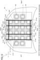
- Figure 2 is a plan view of an inner panel 2 of the automobile hood 1.
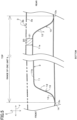
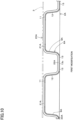
- Figure 3 is a schematic cross-sectional view along a line III-III in Figure 2 .
- Figure 4 is a cross-sectional view along a line IV-IV in Figure 2 , in which illustration of a portion that appears to the rear of the cross-section is omitted. Note that, in Figure 3 and Figure 4 , an outer panel 3 that does not appear in Figure 2 is indicated by a chain double-dashed line that is a virtual line.
- Figure 5 is view in which one part of Figure 3 is enlarged.
- Figure 6 is a plan view in which one part of the inner panel 2 shown in Figure 2 is enlarged.
- Figure 7 is a perspective view in which one part of the inner panel 2 is enlarged.
- the automobile hood 1 is a front hood provided at the front part of an automobile, and is also called a "bonnet".
- An automobile in which the automobile hood 1 is provided is, for example, a passenger vehicle.
- a sedan-type passenger vehicle, a coupe-type passenger vehicle, a hatchback-type passenger vehicle, a minivan-type passenger vehicle, an SUV (Sport Utility Vehicle) type passenger vehicle and the like can be mentioned as examples of the passenger vehicle.
- the terms “front”, “rear”, “left”, “right”, and “upper” and “lower” are used taking a time when the automobile hood 1 is mounted to an automobile and the automobile hood 1 is closed as the basis.
- the term “front” refers to the direction in which the automobile advances.
- the term “rear” refers to the direction in which the automobile reverses.
- the term “right” refers to the turning direction of the automobile when the automobile which is advancing turns to the right.
- the term “left” refers to the turning direction of the automobile when the automobile which is advancing turns to the left.
- the vehicle width direction of the automobile to which the automobile hood 1 is mounted is referred to as “width direction X”.
- the vehicle length direction of the automobile to which the automobile hood 1 is mounted is referred to as “longitudinal direction Y”.
- the vehicle height direction of the automobile to which the automobile hood 1 is mounted is referred to as "height direction Z”.
- the automobile hood 1 has the inner panel 2, the outer panel 3 that is supported by the inner panel 2, sealers 20 provided between the inner panel 2 and the outer panel 3, joints 21 which are portions of the sealers 20 which contact the outer panel 3 and the inner panel 2 and which are portions that join the panels 2 and 3 to each other, and non-joint portions 22 as portions of the sealers 20 that are separated from either one of the inner panel 2 and the outer panel 3.
- the sealers 20 are illustrated using thick lines.
- the outer panel 3 is a portion that constitutes a part of the outer surface of the automobile.
- the outer panel 3 is formed of, for example, a metal material such as a mild steel sheet or a high-tensile strength steel sheet.
- the high-tensile strength steel sheet that can be mentioned include steel sheets having a tensile strength of 340 MPa or more, for example, a steel sheet having a tensile strength of 590 MPa or more.
- the outer panel 3 is formed, for example, by subjecting a single steel sheet to press working or the like. In a case where the outer panel 3 is a steel sheet panel, the sheet thickness of the outer panel 3 is, for example, 0.25 mm to 0.80 mm.
- the outer panel 3 may be an aluminum alloy sheet.
- the sheet thickness of the outer panel 3 is, for example, 0.40 mm to 1.20 mm.
- the outer panel 3 has a shape in which the central portion is upwardly convex in the height direction Z.
- the inner panel 2 reinforces the outer panel 3 by being joined to an undersurface 3a of the outer panel 3 using the sealers 20. By this means, the inner panel 2 increases the panel rigidity of the outer panel 3.
- the inner panel 2 is formed, for example, of a metal material such as a steel sheet.
- the inner panel 2 is formed, for example, by subjecting a single steel sheet to press working.
- the inner panel 2 may be an integrally formed product, or may be formed by joining a plurality of members together. In the present embodiment, the inner panel 2 is an integrally formed product.
- the sheet thickness of the inner panel 2 is, for example, 0.25 mm to 0.80 mm.
- the sheet thickness of the inner panel 2 may be less than the sheet thickness of the outer panel 3, may be the same as the sheet thickness of the outer panel 3, or may be greater than the sheet thickness of the outer panel 3.
- the inner panel 2 may be an aluminum alloy sheet. In a case where the inner panel 2 is an aluminum alloy panel, the sheet thickness of the inner panel 2 is, for example, 0.40 mm to 1.20 mm.
- the inner panel 2 has an outer circumferential portion 4 in which a contour forming portion 5 is provided, and an overhanging structure 6 arranged so as to be surrounded by the contour forming portion 5.
- the outer circumferential portion 4 is an outer circumferential part of the inner panel 2.
- the outer circumferential portion 4 of the inner panel 2 is received by the automobile body (not illustrated) together with the outer circumferential portion of the outer panel 3.
- a load that acts on an upper face 3b of the outer panel 3 is received by the automobile body through the inner panel 2.
- the contour forming portion 5 of the outer circumferential portion 4 is a three-dimensionally shaped portion formed at the outer circumferential part of the inner panel 2, and is a portion at which the bending rigidity is enhanced among the entire outer circumferential portion 4 of the inner panel 2.
- the contour forming portion 5 is formed over the entire area in the circumferential direction of the outer circumferential portion of the inner panel 2.
- the contour forming portion 5 may be formed only at one part in the circumferential direction of the outer circumferential portion 4 of the inner panel 2.
- the contour forming portion 5 includes a portion that rises and falls in the height direction Z when moved in the horizontal direction over the inner panel 2.
- the overhanging structure 6 is arranged so as to be surrounded by the contour forming portion 5.
- the overhanging structure 6 has a three-dimensional structure which is provided in order to receive a load acting on the upper face 3b of the outer panel 3.
- the overhanging structure 6 has a configuration in which members that have a hat-shaped cross section (a V-shaped cross section or a U-shaped cross section) are combined.
- the overhanging structure 6 has a plurality of incomplete units 8 that are adjacent to an inner circumferential edge portion 4a of the outer circumferential portion 4 and continuous with the outer circumferential portion 4, and a plurality of units 9.
- the unit 9 which is adjacent to the outer circumferential portion 4 of the inner panel 2 is connected to the outer circumferential portion 4 directly or through the incomplete unit 8.
- the incomplete unit 8 has a configuration equivalent to a configuration in which one portion of the unit 9 has been cut off along the circumferential direction of the polygonal (in the present embodiment, hexagonal) unit 9.
- the incomplete unit 8 has a side portion that is similar to a sub-unit 10 of the unit 9 that is described later.
- the side portion is continuous with the inner circumferential edge portion 4a of the outer circumferential portion 4.
- each unit 9 is formed in a polygonal (in the present embodiment, hexagonal) annular shape in plan view in the height direction Z.
- plane view when simply the term “plan view” is used, it means a plan view in the height direction Z.
- each unit 9 is formed in the shape of a substantially regular hexagon with rounded corners.
- regular hexagon means a hexagon in which the lengths of the respective sides are equal and the interior angles are also a constant angle of 120 degrees.
- substantially regular hexagon refers to a hexagon that can be treated as a regular hexagon.
- the respective units 9 are formed so that the shape of each unit 9 is substantially the same. Note that, the term “substantially the same” in this case indicates that the configuration is the same except in the respect that the shape of each unit 9 is caused to match a shape which matches the curved shape of the outer panel 3.
- Each unit 9 may also be formed in the shape of a hexagon that is other than a regular hexagon.
- a hexagon other than a regular hexagon that can be mentioned include a hexagon in which the lengths of the respective sides are not uniform, and a hexagon in which the interior angles are not uniform at 120 degrees.
- Examples of a hexagon in which the lengths of the respective sides are not uniform that can be mentioned include a hexagon in which the length of a front end side and the length of a rear end side are set to a predetermined first length, and which has four sides, lengths of which are each set to a predetermined second length that is different from the first length.
- the overhanging structure 6 has a structure in which a plurality of the units 9 having a hexagonal annular shape are disposed in a close-packed arrangement.
- the term "close-packed” means that a plurality of the units 9 that are adjacent to each other are arranged without a gap therebetween.
- each unit 9 is partitioned off from the other units 9 by unit boundaries 14.
- a front end 13c (lower end) of a bottom portion 13 forms a boundary of the bottom portion 13 that includes the front end 13c, to thereby form the unit boundary 14.
- the unit boundary 14 is formed in a hexagonal shape in plan view.
- a plurality of the units 9 have the same shape.
- the units 9 that have similar forms to each other and have differing shapes may be disposed in a close-packed arrangement. Note that, in the overhanging structure 6, the units 9 need not be disposed in a close-packed arrangement, and another portion may be formed between the units 9 and 9 that are adjacent.
- the plurality of the units 9 are formed symmetrically in the width direction X as a whole.
- three of the units 9 are arranged side by side in the front-to-rear direction at the center in the width direction X. Note that, there is no constraint on the direction of the units 9.
- the aforementioned three units 9 arranged at the central position in the width direction X are provided, in the following order, four units 9 which are arranged side by side in the longitudinal direction Y, a further three units 9 which are arranged side by side in the longitudinal direction Y, a further two units 9 which are arranged side by side in the longitudinal direction Y, and a further two units 9 which are arranged side by side in the longitudinal direction Y.
- each of the units 9 has six of the sub-units 10 (10a to 10f).
- a front sub-unit 10a and a rear sub-unit 10d extend along the width direction X, respectively.
- the remaining four sub-units 10 extend in a direction that inclines with respect to the longitudinal direction Y in plan view.
- the unit 9 that has a polygonal shape is formed by the plurality of sub-units 10 in this way.
- Each of the sub-units 10 (10a to 10f) has a flange 11, an inclined wall 12 continuous with the flange 11, and the bottom portion 13 that is continuous with the inclined wall 12 and is separated from the flange 11.
- the flange 11 is adjacent to the outer panel 3, and in the sub-unit 10, the flange 11 is a portion that is arranged closest to the outer panel 3.
- the flange 11 is a strip-shaped portion.
- outer circumferential portions of the flanges 11 of the six sub-units 10a to 10f form a hexagonal flange as a whole.
- the plurality of flanges 11 are formed in an annular shape as a whole.
- the outer circumferential portions of the flanges 11 of the six sub-units 10a to 10f may, as a whole, form a flange having a polygonal shape other than a hexagon, and may form a substantially circular flange, or may form a flange having a substantially oval shape.
- inner end portions 11a of the six flanges 11 constitute an annular end portion which is centered on the center of the annular unit 9 as a whole.
- the inner end portions 11a of the six flanges 11 are formed in a circular shape as a whole.
- the inner end portions 11a of the six flanges 11 may be formed in a polygonal shape as a whole, or may be formed in an elliptical shape as a whole.
- the plurality of flanges 11 in the plurality of units 9 are disposed in a close-packed arrangement.
- a width to which a joint 21 can be applied is preferably 2 mm or more from the viewpoint that a sufficient amount of the joint 21 can be provided.
- Each of the two end portions of the flange 11 in the longitudinal direction is formed in a curved shape in plan view, and smoothly connects with the flange 11 of an adjacent sub-unit 10.
- the flanges 11 of at least some of the sub-units 10 are adhered to the joint 21 at the upper face 11b, and are adhered to the outer panel 3 through the joint 21.
- the inclined wall 12 extends downward from the flange 11.
- the inclined wall 12 is disposed between the flange 11 and the bottom portion 13, and connects the flange 11 and the bottom portion 13.
- the inclined wall 12 extends from the flange 11 so as to separate from the outer panel 3.
- the inclined wall 12 is provided over the entire area in a longitudinal direction L of the sub-unit 10 in which the inclined wall 12 in question is provided.
- the inclined wall 12 is formed, for example, in a tapered shape that advances toward the central axis side (the inner end portion 11a side) of the unit 9 as it approaches the outer panel 3 side.
- the flange 11 is continuous with the upper end of the inclined wall 12.
- the bottom portion 13 is continuous with the lower end of the inclined wall 12.
- the bottom portion 13 is a portion that is farthest from the outer panel 3, and is separated from the flange 11.
- the bottom portion 13 is formed in a curved shape which is convex in the downward direction.
- the bottom portion 13 is provided over the entire area in the longitudinal direction of the sub-unit 10 in which the inclined wall 12 in question is provided.
- the flange 11, the inclined wall 12, and the bottom portion 13 are arranged in that order from the inner side to the outer side in the radial direction of the unit 9.
- the front end 13c of the bottom portion 13 in one unit 9 is integral with the front end 13c of the bottom portion 13 in another unit 9 that is adjacent thereto.
- the sealer 20 is provided for joining the inner panel 2 and the outer panel 3.
- the sealer 20 is an adhesive.
- a mastic sealer (mastic adhesive) can be exemplified as the adhesive.
- a resin-based adhesive can be exemplified as the mastic sealer.
- the adhesive may have a property of being cured at normal temperature (for example, 20 degrees Celsius), or may have a property of being cured by undergoing a heating process or a drying process.
- the sealer 20 is arranged so as to secure the bonding strength between the inner panel 2 and the outer panel 3 while achieving a reduction in the weight of the automobile hood 1.
- the sealer 20 is provided in each unit 9 of the inner panel 2.
- the width of the sealer 20 (the dimension of the sealer 20 in the direction orthogonal to the extending direction of the sealer 20 in plan view) is about 5 mm to 25 mm.
- a portion of the sealer 20 that is in contact with both of the inner panel 2 and the outer panel 3 constitutes a joint 21.
- a portion that is actually in contact with both of the inner panel 2 and the outer panel 3 is the joint 21 that joins these panels 2 and 3 to each other.
- the joint 21 joins the upper face 11b of the flange 11 and the undersurface 3a of the outer panel 3.
- the flange 11 of the inner panel 2 that is a flange which projects to the outer panel 3 side being joined to the outer panel 3 through the joint 21, the inner panel 2 can support the outer panel 3 with high rigidity.
- linear sealer region A refers to a region in which the sealer 20 is continuously provided and extends in a linear shape.
- linear shape in this case is not limited to the case of a true straight line, and also includes a case where the sealer 20 meanders or curves within a range of about three times the width of the sealer 20 in a direction orthogonal to the longitudinal direction of the sealer 20 in plan view.
- At least three (in the present embodiment, nine) of the linear sealer regions A are provided.
- the linear sealer regions A (A1 to A9) are provided.
- a place where the sealer 20 is provided is a sealer region (linear sealer region A).
- the direction in which the relevant linear sealer region A1 to A9 extends is defined as a longitudinal direction L (L1 to L9).
- the longitudinal direction L is a direction on a straight line connecting the center of one end and the center of the other end of the sealer 20 in each linear sealer region A.
- the respective longitudinal directions L1 to L6 of the linear sealer regions A1 to A6 are directions that extend from the lower left to the upper right in plan view
- the longitudinal direction L7 of the linear sealer region A7 is a direction along the width direction X
- the respective longitudinal directions L8 and L9 of the linear sealer regions A8 and A9 are directions from the lower left to the upper right.
- the longitudinal directions L1 to L6 are indicated collectively, they are different directions to each other.
- the linear sealer region A1 is arranged at the left end of the linear sealer regions A1 to A9. Further, the linear sealer regions A1 to A6 which are parallel to each other are arranged from the left side to the right side.
- the linear sealer region A7 is continuous with the front end of the linear sealer region A1, and in addition, the linear sealer regions A7 and A8 are continuous with each other. Further, the linear sealer region A9 is continuous with the rear end of the linear sealer region A3.
- Each of the linear sealer regions A1 to A9 is provided within the overhanging structure 6.
- the linear sealer regions A1 to A5 extend over a plurality of the units 9. Specifically, the linear sealer region A1 extends over four of the units 9 that are arranged in series from the lower left to the upper right.
- the linear sealer region A2 extends over six of the units 9 that are arranged in series from the lower left to the upper right.
- the linear sealer region A3 extends over five of the units 9 that are arranged in series from the lower left to the upper right.
- the linear sealer region A4 extends over five of the units 9 that are arranged in series from the lower left to the upper right.
- the linear sealer region A5 extends over four of the units 9 that are arranged in series from the lower left to the upper right.
- the linear sealer region A6 is arranged in one of the units 9. Note that, the linear sealer regions A7 and A8 are arranged in the incomplete unit 8 at the front end. Further, the linear sealer region A9 is arranged in the incomplete unit 8 on the rear end side.
- each unit 9 only one linear sealer region A is provided. Specifically, in a direction orthogonal to the longitudinal direction L of the linear sealer regions A1 to A6, the linear sealer region A is arranged only on one of a pair of end portions of each unit 9. In other words, in the linear sealer regions A1 to A6 as at least one of the plurality of linear sealer regions, all the joints 21 are arranged at places that are offset from the center (the center point of the circle of the inner end portions 11a) of the flanges 11. By means of the above configuration relating to the sealer 20, the total weight of the sealer 20 in the automobile hood 1 can be reduced.
- each of the linear sealer regions A1 to A5 extends over a plurality of the units 9. Therefore, each of the sealers 20 of the linear sealer regions A1 to A5 extends while rising and falling in the height direction Z. With regard to the linear sealer region A6 also, the sealer 20 extends while rising and falling in the height direction Z. Further, in the sealer 20 of each of the linear sealer regions A1 to A6, a portion that is mounted on the flange 11 constitutes the joint 21. Specifically, the joints 21 are arranged in each of the linear sealer regions A1 to A6. In each of the linear sealer regions A1 to A5, the joints 21 are intermittently arranged in the longitudinal direction L.
- a place that is mounted on the flange 11 constitutes the joint 21 as described above.
- the respective sealers 20 of the linear sealer regions A1 to A5 form respective joints 21 at the flanges 11 of a plurality of the units 9.
- a place arranged on the inclined wall 12 or the bottom portion 13 constitutes a non-joint portion 22 which does not join the inner panel 2 and the outer panel 3 to each other.
- the joints 21 and the non-joint portions 22 are alternately arranged in the corresponding longitudinal direction L1 to L6.
- each of the linear sealer regions A1 to A5 approximately 70% of the region is the joints 21, and the remaining about 30% of the region is the non-joint portions 22.
- a portion of the sealer 20 that is mounted on the flange 11 of the incomplete unit 8 constitutes the joint 21.
- the joint 21 is formed in each of the linear sealer regions A1 to A9. Note that, it suffices that the joint 21 is formed in at least three longest linear sealer regions A2, A4 and A3 among the plurality of linear sealer regions A1 to A9.
- At least three of the linear sealer regions A are provided at intervals in at least one of the longitudinal direction Y as the front-rear direction of the automobile hood 1 and the width direction X.
- the linear sealer region A2 is arranged diagonally to the rear of the linear sealer regions A1, A7, and A8.
- the linear sealer regions A3, A4, and A5 are arranged in that order toward the rear.
- the linear sealer region A9 is arranged to the rear of the linear sealer region A3.
- the linear sealer region A6 is arranged on the diagonally rear side of the linear sealer region A5.
- at least three of the linear sealer regions A are provided at intervals in both of the longitudinal direction Y and the width direction X.
- a region of the inner panel 2 which includes one linear sealer region A and in which both ends in the longitudinal direction L reach the outer circumferential edge of the inner panel 2 is defined as an end-to-end region B.
- a region of the automobile hood 1 which includes one linear sealer region A and which is present along the longitudinal direction L is defined as an end-to-end region B.
- the end-to-end region B is a region of the inner panel 2 which includes the linear sealer region A and which is aligned in the longitudinal direction L with the linear sealer region A (which includes the linear sealer region A and regions aligned with the linear sealer region A).
- end-to-end regions B1 to B9 that include the linear sealer regions A1 to A9, respectively, are defined.
- the end-to-end region B1 is a region of the inner panel 2 that includes the linear sealer region A1 and in which both ends in the longitudinal direction L of the linear sealer region A1 reach the outer circumferential edge of the inner panel 2.
- a pair of end portions B1a and B1b of the end-to-end region B 1 are located at the left rear edge and the front edge of the inner panel 2, respectively.
- the end-to-end regions B2 to B4 are regions of the inner panel 2 that include the corresponding linear sealer regions A2 to A4 and in which both ends in the corresponding longitudinal directions L2 to L4 of the linear sealer regions A2 to A4 reach the outer circumferential edge of the inner panel 2.
- the respective pairs of end portions B2a and B2b, B3a and B3b, and B4a and B4b of the end-to-end regions B2 to B4 are located at the left rear edge and the front edge of the inner panel 2, respectively.
- the end-to-end regions B5 and B6 are regions of the inner panel 2 that include the corresponding linear sealer regions A5 and A6 and in which both ends in the corresponding longitudinal directions L5 and L6 of the linear sealer regions A5 and A6 reach the outer circumferential edge of the inner panel 2.
- the respective pairs of end portions B5a and B5b, and B6a and B6b of the end-to-end regions B5 and B6 are located at the rear edge and the right edge of the inner panel 2, respectively.
- three longest linear sealer regions A in lengths in the longitudinal direction L among the linear sealer regions A1 to A9 are, in order of longest length, the linear sealer regions A2, A4, and A3.
- the lengths of the three longest linear sealer regions A2, A4, and A3 among the plurality of linear sealer regions A are 40% or more of the lengths of the end-to-end regions B2, B4 and B3 to which the linear sealer regions A2, A4 and A3 themselves belong, respectively.
- the proportion of the respective lengths with respect to the lengths of the corresponding end-to-end regions B2, B4 and B3 in the corresponding longitudinal directions L2 to L4 is 40% or more respectively. More specifically, in plan view, in the longitudinal direction L2, the proportion of the length of the linear sealer region A2 with respect to the length between the end portions B2a and B2b of the end-to-end region B2 is 40% or more. Further, in plan view, in the longitudinal direction L3, the proportion of the length of the linear sealer region A3 with respect to the length between the end portions B3a and B3b of the end-to-end region B3 is 40% or more. Further, in plan view, in the longitudinal direction L4, the proportion of the length of the linear sealer region A4 with respect to the length between the end portions B4a and B4b of the end-to-end region B4 is 40% or more.
- the grounds for setting the respective lengths of the three longest linear sealer regions A2, A4, and A3 among the plurality of linear sealer regions A to 40% or more of the respective lengths of the corresponding end-to-end regions B2, B4 and B3 to which the linear sealer regions A2, A4 and A3 themselves belong in this way is as follows. Specifically, in the automobile hood 1, for reasons pertaining to the design and the design space, in a region up to a maximum of about 30% of an outer circumferential side portion of the automobile hood 1, (1) the rigidity of the outer panel 3 is high and it is not necessary for the region to be stiffened using the inner panel 2.
- the lengths of the linear sealer regions A other than the three longest linear sealer regions A in lengths in the longitudinal direction L among the linear sealer regions A1 to A9 are not particularly defined except for the point that the lengths are shorter than the lengths of the three longest linear sealer regions A2, A4 and A3.
- the end-to-end regions B2, B4 and B3 of the aforementioned three longest linear sealer regions A2, A4 and A3 among the plurality of linear sealer regions A1 to A9 are arranged so that intersection of the end-to-end regions B2, B4 and B3 with each other is avoided (the end-to-end regions B2, B4 and B3 are separated).
- the end-to-end regions B2, B4 and B3 are arranged in a linear shape extending from the lower left to the upper right in plan view, and are substantially parallel to each other. Hence, the end-to-end regions B2, B4 and B3 do not intersect with each other in the region surrounded by the outer circumferential edge of the inner panel 2.
- the joints 21 of the linear sealer regions A1 to A6 are arranged over two flanges 11 and 11 that are adjacent to each other. Specifically, in each unit 9, the joints 21 are arranged over the flanges 11 of the sub-units 10c and 10d. Further, only one linear sealer region A of the plurality of linear sealer regions A is passed over one unit 9.
- the joints 21 are arranged in a well-balanced manner in the automobile hood 1. Specifically, the joints 21 are arranged on both sides of the center of the automobile hood 1 in the width direction X, and are scattered in a region of at least 40% or more of the total width of the automobile hood 1. Similarly, the joints 21 are arranged on both sides of the center of the automobile hood 1 in the longitudinal direction Y, and are scattered in a region of at least 40% or more of the total length of the automobile hood 1.
- the inner panel 2, the outer panel 3, and the sealer 20 are prepared.
- the inner panel 2 or the outer panel 3 is held by a jig or the like as an application target.
- a robot arm applies a sealer nozzle to the application target so as to apply the sealer 20 to form the arrangement illustrated in Figure 2 .
- a robot arm or the like is used to fit together the application target and the inner panel 2 or outer panel 3 that is different from the application target. By this means, some of the sealer 20 comes into contact with both of the inner panel 2 and the outer panel 3 to form the joints 21.
- the outer circumferential edge portion of the outer panel 3 is subjected to hemming to complete the automobile hood 1.
- the three longest linear sealer regions A2, A4 and A3 among the linear sealer regions A1 to A9 are each a length that is 40% or more of the length of the corresponding end-to-end regions B2, B4 and B3 to which the linear sealer regions A2, A4 and A3 themselves belong, respectively, and the joints 21 are formed in these linear sealer regions A2, A4 and A3.
- the three end-to-end regions B2, B4 and B3 that include the aforementioned three longest linear sealer regions A2, A4 and A3 do not intersect with each other within the region surrounded by the outer circumferential edge of the inner panel 2.
- an operation to apply the sealer 20 can be performed by moving the nozzle that applies the sealer 20 along a simple path.
- the time required for the application process can be made shorter through the efficient application of the sealer 20.
- the sealer 20 can be applied in long linear shapes, the movement of the robot arm when applying the sealer 20 using the robot arm can be made simpler, and the life of the robot arm can be extended through a reduction in the load on the robot arm in comparison to a case where the robot arm performs complicated movements.
- the length of the joints 21 can be sufficiently secured and these three linear sealer regions A2, A4, and A3 can be arranged in a well-balanced manner so as not to intersect with each other.
- the joining strength between the inner panel 2 and the outer panel 3 can be sufficiently secured using the joints 21.
- the efficiency of the operation for joining the inner panel 2 and the outer panel 3 can be increased while making the joining strength with which the inner panel 2 and the outer panel 3 are joined to each other sufficiently high.
- the joints 21 are intermittently arranged in the corresponding longitudinal directions L1 to L5. According to this configuration, while quickly applying the sealer 20 in straight lines, the joints 21 can be arranged at places that are suitable for joining the inner panel 2 and the outer panel 3.
- the joints 21 and the non-joint portions 22 are alternately arranged in the longitudinal directions L2, L4 and L3, respectively.
- the joints 21 can be applied in a well-balanced manner to a wider area in the automobile hood 1.
- the efficiency of the operation for joining the inner panel 2 and the outer panel 3 can be further increased while making the joining strength with which the inner panel 2 and the outer panel 3 are joined to each other sufficiently high.
- the plurality of linear sealer regions A1 to A6 are arranged in parallel with each other. According to this configuration, the plurality of linear sealer regions A1 to A6 can be collectively formed by, for example, moving a plurality of (three) nozzles linearly two times. Hence, the operation to apply the sealer 20 can be performed more quickly.
- the joints 21 of the linear sealer regions A1 to A5 are provided on flanges 11 of a plurality of the units 9. According to this configuration, by performing the operation of forming one linear sealer region A which can be completed in a short time, the joints 21 can be collectively provided on the flanges 11 of a plurality of the units 9.
- a plurality of the units 9 that have the same shape are arranged in the longitudinal direction Y and the width direction X of the automobile hood 1.
- the efficiency of applying the sealer 20 can be made very high, and assembly of the automobile hood 1 can be completed in a shorter time through shortening of the time required to perform the sealer application operation.
- the sealer 20 has been described by taking as an example a form in which the sealer 20 extends from the lower left to the upper right.
- the form of the sealer 20 may be different from the form described in the above example.
- the sealer 20 may be arranged symmetrically in the width direction X with respect to the arrangement shown in Figures 2 and 6 , or may be arranged symmetrically in the longitudinal direction Y.
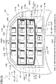
- Figure 8 is a plan view of the inner panel 2 of the automobile hood 1 in a modification in which reinforcing sealers are provided in the embodiment.
- reinforcing sealers 30 to 39 are additionally provided.
- the reinforcing sealers 30 to 39 are provided to connect together end portions of joints 21 of the linear sealer regions A1 to A6, A8, and A9 that are end portions which are not in contact with another linear sealer region.
- the linear sealer region A1 has an end portion 21a that is disposed on the leftmost side in an end portion joint 21 arranged at an endmost portion on one side (the left side) in the longitudinal direction L1 of the linear sealer region A1 among the plurality of joints 21.
- the linear sealer regions A2, A4, A5, A6, and A9 have end portions 21b to 21f that are respectively disposed on the leftmost side in an end portion joint 21 arranged at an endmost portion on one side (the left side) in the longitudinal direction L of the corresponding linear sealer region A2, A4, A5, A6 or A9.
- the linear sealer region A2 has an end portion 21g that is disposed on the rightmost side in an end portion joint 21 that is arranged at an endmost portion on the other side (the right side) in the longitudinal direction L2 of the linear sealer region A2 among the plurality of joints 21.
- the linear sealer regions A3 to A6, and A8 have end portions 21h to 211 that are respectively disposed on the rightmost side in an end portion joint 21 arranged at an endmost portion on the other side (the right side) in the longitudinal direction L of the corresponding linear sealer region A3, A4, A5, A6, or A8.
- the reinforcing sealers 30 to 39 connect together the end portions 21a to 21l of the end portion joints 21 of the plurality of linear sealer regions A1 to A6, A8 and A9 with longitudinal directions L different from each other. Further, in the present embodiment, by passing over at least one of the flanges 11, the respective reinforcing sealers 30 to 39 are joined to both of the inner panel 2 and the outer panel 3 to form the joints 21. Specifically, in the reinforcing sealers 30 to 39, a place that is disposed on the flange 11 is the joint 21.
- the reinforcing sealer 30 connects together the end portions 21a and 21b of the end portion joints 21 of the linear sealer regions A1 and A2 that are adjacent.
- One part of the reinforcing sealer 30 is arranged on the flange 11 between the linear sealer regions A1 and A2, and this portion forms the joint 21.
- the reinforcing sealer 31 connects together the end portions 21b and 21c of the end portion joints 21 of the linear sealer regions A2 and A9 that are adjacent.
- One part of the reinforcing sealer 31 is arranged on the flange 11 of the incomplete unit 8 between the linear sealer regions A2 and A9, and this portion forms the joint 21.
- the reinforcing sealer 32 connects together the end portions 21c and 21d of the end portion joints 21 of the linear sealer regions A9 and A4 that are adjacent.
- One part of the reinforcing sealer 32 is arranged on the flange 11 of the incomplete unit 8 and the flange 11 of the unit 9 between the linear sealer regions A9 and A4, and this portion forms the joint 21.
- the reinforcing sealer 33 connects together the end portions 21d and 21e of the end portion joints 21 of the linear sealer regions A4 and A5 that are adjacent.
- One part of the reinforcing sealer 33 is arranged on the flange 11 of the incomplete unit 8 and the flange 11 of the unit 9 between the linear sealer regions A4 and A5, and this portion forms the joint 21.
- the reinforcing sealer 34 connects together the end portions 21e and 21f of the end portion joints 21 of the linear sealer regions A5 and A6 that are adjacent.
- One part of the reinforcing sealer 34 is arranged on the flange 11 of the incomplete unit 8 and the flange 11 of the unit 9 between the linear sealer regions A5 and A6, and this portion forms the joint 21.
- the reinforcing sealer 35 connects together end portions 21k and 21j of the end portion joints 21 of the linear sealer regions A6 and A5 that are adjacent.
- One part of the reinforcing sealer 35 is arranged on the flange 11 of the unit 9 between the linear sealer regions A6 and A5, and this portion forms the joint 21.
- the reinforcing sealer 36 connects together end portions 21j and 21i of the end portion joints 21 of the linear sealer regions A5 and A4 that are adjacent.
- One part of the reinforcing sealer 36 is arranged on the flange 11 of the incomplete unit 8 and the flange 11 of the unit 9 between the linear sealer regions A5 and A4, and this portion forms the joint 21.
- the reinforcing sealer 37 connects together end portions 21i and 21h of the end portion joints 21 of the linear sealer regions A4 and A3 that are adjacent.
- One part of the reinforcing sealer 35 is arranged on the flange 11 of the unit 9 between the linear sealer regions A4 and A3, and this portion forms the joint 21.
- the reinforcing sealer 38 connects together end portions 21h and 21g of the end portion joints 21 of the linear sealer regions A3 and A2 that are adjacent.
- One part of the reinforcing sealer 38 is arranged on the flange 11 of the incomplete unit 8 and the flange 11 of the unit 9 between the linear sealer regions A3 and A2, and this portion forms the joint 21.
- the reinforcing sealer 39 connects together end portions 21g and 21l of the end portion joints 21 of the linear sealer regions A2 and A8 that are adjacent.
- One part of the reinforcing sealer 39 is arranged on the flange 11 of the incomplete unit 8 and the flange 11 of the unit 9 between the linear sealer regions A2 and A8, and this portion forms the joint 21.
- each of the reinforcing sealers 30 to 39 extends in a direction that intersects with each of the longitudinal directions L of the corresponding adjacent two linear sealer regions A.
- the reinforcing sealers 30 to 39 cooperate with the sealers 20 of a plurality of linear sealer regions to form an annular sealer 40.
- the outer circumference of the annular sealer 40 is formed by the linear sealer region A1, the reinforcing sealers 30 to 34, the linear sealer region A6, the reinforcing sealers 35 to 39, and the linear sealer regions A8 and A7.
- the reinforcing sealers 30 to 39 are provided that connect together the end portions 21a to 211 of the end portion joints 21 of the plurality of linear sealer regions A1 to A6, A8, and A9 with longitudinal directions L different from each other.
- a state is not entered in which the joints 21 are abruptly discontinued at the end portions 21a to 211. If a state is entered in which the joints 21 are abruptly discontinued at the end portions 21a to 211, a change in the strength of the outer panel 3 in the vicinity of the end portions 21a to 211 will be large.
- the reinforcing sealers 30 to 39 cooperate with the linear sealer regions A1, A6, A7, and A8 to form the annular sealer 40. According to this configuration, high dent resistance can be secured at the outer circumferential side portion of the outer panel 3. Further, by applying the reinforcing sealers 30 to 39 in an annular shape, the time required for applying the reinforcing sealers 30 to 39 can be further shortened.
- the respective reinforcing sealers 30 to 39 need not be directly connected to the adjacent linear sealer regions A which the reinforcing sealers 30 to 39 connect, and there may be a gap of about several tens of mm or less therebetween.
- a part of the annular sealer 40 may be interrupted.
- a sealer having a dotted-line shape may be formed by a midway portion of the sealer being interrupted.
- the sealer having a dotted-line shape may be a sealer consisting of two sections, or may be a sealer consisting of three or more sections.
- the unit 9 is described using an example of the unit 9 that has a hexagonal shape.
- the unit need not have a hexagonal shape.
- an overhanging structure 6A (overhanging structure with a small frame structure) that includes a plurality of units 9A formed in a quadrangular shape as a polygonal shape may be provided.
- Figure 9 is a schematic plan view of an inner panel 2A and a sealer 20A pertaining to a first modification.
- Figure 10 is a cross-sectional view along a line X-X in Figure 9 .
- the overhanging structure 6A has a configuration in which the units 9A are disposed in a close-packed arrangement.
- each unit 9A is formed in a rectangular shape with rounded corners.
- Each unit 9A is formed in substantially the same shape.
- the term "substantially the same” indicates that the configurations are the same except that the shape of each unit 9A is made to conform to a shape that is matched to the curved shape of the outer panel 3.
- Each unit 9A may be formed in a quadrangle other than a rectangle, such as a square. Note that, in the overhanging structure 6A, the units 9A need not be disposed in a close-packed arrangement, and another portion may be formed between the units 9A and 9A that are adjacent.
- Each of the units 9A has four of the sub-units 10 (10a to 10d).
- the sub-unit 10a and the sub-unit 10c are arranged separated from each other in the longitudinal direction Y.
- the sub-unit 10b and the sub-unit 10d are arranged separated from each other in the width direction X.
- Each of the sub-units 10 (10a to 10d) has the flange 11, the inclined wall 12 continuous with the flange 11, and the bottom portion 13 that is continuous with the inclined wall 12 and is separated from the flange 11.
- each unit 9A The plurality of flanges 11 of each unit 9A are formed in an annular shape as a whole.
- the front ends 13c of the bottom portions 13 of the four sub-units 10 form a single unit boundary 14A having a square shape as a whole.
- the units 9A and 9A that are adjacent are continuous with each other.
- the units 9A are arranged in a grid pattern. Further, the units 9A are arranged in a plurality of rows (for example, four rows) in the longitudinal direction Y.
- the number of units 9A in each of the two unit rows near the center in the longitudinal direction Y is greater than the number of units 9A in the unit row of units 9A on the front end side, and is also greater than the number of units 9A in the unit row of units 9A on the rear end side.
- the sealer 20A is provided for joining the inner panel 2A and the outer panel 3 to each other.
- the sealer 20A is provided in each unit 9A of the inner panel 2A.
- a portion of the sealer 20A that is in contact with both of the inner panel 2A and the outer panel 3 constitutes a joint 21A.
- portions that are actually in contact with both of the inner panel 2A and the outer panel 3 are joints 21A that join these panels 2A and 3 to each other.
- At least one part (in the present embodiment, all) of the sealer 20A is arranged in a linear sealer region AA. At least three (in the present embodiment, four) linear sealer regions AA are provided. In the present embodiment, linear sealer regions AA (AA1 to AA4) are provided.
- the direction in which the relevant linear sealer regions AA1 to AA4 extend is defined as a longitudinal direction LA (LA1 to LA4).
- the longitudinal direction LA is a direction along a straight line connecting the center of one end and the center of the other end of the sealer 20A in each of the linear sealer regions AA1 to AA4.
- the longitudinal direction LA of each of the linear sealer regions AA1 to AA4 is along the width direction X.
- the linear sealer regions AA1 to AA4 are arranged in that order from the row of units 9A on the front end side, and are arranged in parallel with each other.
- the linear sealer regions AA1 to AA4 are provided at intervals in the longitudinal direction Y.
- Each of the linear sealer regions AA1 to AA4 is provided within the overhanging structure 6A.
- Each of the linear sealer regions AA1 to AA4 extends over a plurality of the units 9A. Specifically, each of the linear sealer regions AA1 to AA4 extends over all of the units 9A in a single row aligned in the width direction X.
- each of the linear sealer regions AA1 to AA4 extends over a plurality of units 9A. Therefore, each of the sealers 20A of the linear sealer regions AA1 to AA4 extends while rising and falling in the height direction Z. Further, in the sealer 20A of each of the linear sealer regions AA1 to AA4, a portion that is mounted on a flange 11 constitutes a joint 21A. Specifically, the joints 21A are arranged in each of the linear sealer regions AA1 to AA4. The joint 21A is a portion that joins the panels 2A and 3 to each other. In each of the linear sealer regions AA1 to AA4, the joints 21A are intermittently arranged in the longitudinal direction L.
- the joints 21A of the sealer 20A of the linear sealer regions AA1 to AA4 are provided on the flanges 11 of a plurality of the units 9A.
- a place that is in contact with the inclined wall 12 or the bottom portion 13 constitutes a non-joint portion 22A which does not join the inner panel 2A and the outer panel 3 to each other.
- the non-joint portion 22A is a portion of the sealer 20A that is separated from either one of the inner panel 2A and the outer panel 3.
- the joints 21A and the non-joint portions 22A are alternately arranged.
- all the joints 21A of each of the linear sealer regions AA1 to AA4 are arranged at places that are offset from the center (centroid) of the flanges 11 of each unit 9A. Further, the sealer 20A of each of the linear sealer regions AA1 to AA4 forms respective joints 21A on the flange 11 of a plurality of the units 9A.
- a region of the inner panel 2A which includes one linear sealer region AA and in which both ends in the longitudinal direction LA reach the outer circumferential edge of the inner panel 2A is defined as an end-to-end region BA.
- each of the end-to-end regions BA1 to BA4 is a region of the inner panel 2A that includes the corresponding linear sealer region AA1, AA2, AA3 or AA4, and in which both ends in the longitudinal direction LA of the relevant linear sealer region AA1, AA2, AA3 or AA4 reach the outer circumferential edge of the inner panel 2A.
- each of the three longest linear sealer regions AA2, AA3 and AA4 among the plurality of linear sealer regions AA1 to AA4 has a length that is 40% or more of the length of the corresponding end-to-end region BA2, BA3 or BA4 to which the relevant linear sealer region AA2, AA3 or AA4 itself belongs.
- the end-to-end regions BA2, BA3 and BA4 of the aforementioned three longest linear sealer regions AA2, AA3 and AA4 among the plurality of linear sealer regions AA1 to AA4 do not intersect with each other within a region surrounded by the outer circumferential edge of the inner panel 2A.
- the joints 21A of the linear sealer regions AA1 to AA4 are arranged on the flange 11 that is at the front end in each unit 9A. Further, only one linear sealer region AA is passed over one unit 9A.
- Figure 11 is a plan view of the inner panel 2A of the automobile hood 1 in a modification in which reinforcing sealers are provided in the first modification.
- reinforcing sealers 30A to 35A are additionally provided.
- the reinforcing sealers 30A to 35A are provided to, among the joints 21A of the linear sealer regions AA1 to AA4, connect together end portions which are not in contact with another linear sealer region.
- the linear sealer region AA1 has an end portion 21aA that is disposed on the leftmost side in an end portion joint 21A arranged at an endmost portion on one side (the left side) in the longitudinal direction LA1 of the linear sealer region AA1 among the plurality of joints 21A.
- the linear sealer regions AA2 to AA4 have end portions 21bA to 21dA, respectively, each of which is disposed on the leftmost side in an end portion joint 21A arranged at an endmost portion on one side (the left side) in the longitudinal direction LA of the corresponding linear sealer region AA2, AA3 or AA4.
- linear sealer regions AA1 to AA4 have end portions 21eA to 21hA, respectively, each of which is disposed on the rightmost side in an end portion joint 21A that, among the plurality of joints 21A, is arranged at an endmost portion on the other side (right side) in the longitudinal direction L of the corresponding linear sealer region AA1, AA2, AA3 or AA4.
- the reinforcing sealers 30A to 35A connect together the end portions 21aA to 21hA of the end portion joints 21A of the plurality of linear sealer regions AA1 to AA4 with longitudinal directions L different from each other. Further, in the present modification, by passing over at least one of the flanges 11, the respective reinforcing sealers 30A to 35A are joined to both of the inner panel 2A and the outer panel 3 to form the joints 21A. Specifically, in the reinforcing sealers 30A to 35A, a place that is disposed on the flange 11 is the joint 21A.
- the reinforcing sealer 30A connects together the end portions 21aA and 21bA of the end portion joints 21 of the linear sealer regions AA1 and AA2 that are adjacent.
- One part of the reinforcing sealer 30A is arranged on the flange 11 of the unit 9 between the linear sealer regions AA1 and AA2, and this portion forms the joint 21A.
- the reinforcing sealer 31A connects together the end portions 21bA and 21cA of the end portion joints 21A of the linear sealer regions AA2 and AA3 that are adjacent.
- One part of the reinforcing sealer 31A is arranged on the flange 11 of the unit 9 between the linear sealer regions AA2 and AA3, and this portion forms the joint 21A.
- the reinforcing sealer 32A connects together the end portions 21cA and 21dA of the end portion joints 21A of the linear sealer regions AA3 and AA4 that are adjacent.
- One part of the reinforcing sealer 32A is arranged on the flange 11 of the unit 9A between the linear sealer regions AA3 and AA4, and this portion forms the joint 21A.
- the reinforcing sealer 33A connects together the end portions 21hA and 21gA of the end portion joints 21 of the linear sealer regions AA4 and AA3 that are adjacent.
- One part of the reinforcing sealer 33A is arranged on the flange 11 of the unit 9A between the linear sealer regions AA4 and AA2, and this portion forms the joint 21A.
- the reinforcing sealer 34A connects together the end portions 21gA and 21fA of the end portion joints 21A of the linear sealer regions AA3 and AA2 that are adjacent.
- One part of the reinforcing sealer 34A is arranged on the flange 11 of the unit 9A between the linear sealer regions AA3 and AA2, and this portion forms the joint 21A.
- the reinforcing sealer 35A connects together the end portions 21fA and 21eA of the end portion joints 21A of the linear sealer regions AA2 and AA1 that are adjacent.
- One part of the reinforcing sealer 35A is arranged on the flange 11 of the unit 9A between the linear sealer regions AA2 and AA1, and this portion forms the joint 21A.
- each of the reinforcing sealers 30A to 35A extends in a direction that intersects with each of the longitudinal directions LA of the corresponding adjacent two linear sealer regions AA.
- the reinforcing sealers 30A to 35A cooperate with the sealers 20A of a plurality of linear sealer regions to form an annular sealer 40A.
- the outer circumference of the annular sealer 40A is formed by the linear sealer region AA1, the reinforcing sealers 30A to 32A, the linear sealer region AA4, and the reinforcing sealers 33A to 35A.
- the reinforcing sealers 30A to 35A are provided that connect together the end portions 21aA to 21hA of the end portion joints 21A of the plurality of linear sealer regions AA1 to AA4 with longitudinal directions L different from each other.
- a state is not entered in which the joints 21A are abruptly discontinued at the end portions 21aA to 21hA. If a state is entered in which the joints 21A are abruptly discontinued at the end portions 21aA to 21hA, a change in the strength of the outer panel 3 in the vicinity of the end portions 21aA to 21hA will be large.
- the reinforcing sealers 30A to 35A cooperate with the linear sealer regions AA1 and AA4 to form the annular sealer 40A. According to this configuration, high dent resistance can be secured at the outer circumferential side portion of the outer panel 3. Further, by applying the reinforcing sealers 30A to 35A in an annular shape, the time required for applying the reinforcing sealers 30A to 35A can be further shortened.
- the respective reinforcing sealers 30A to 35A need not be directly connected to the adjacent linear sealer regions A which the reinforcing sealers 30A to 35A connect, and there may be a gap of about several tens of mm or less therebetween.
- a part of the annular sealer 40A may be interrupted.
- a sealer having a dotted-line shape may be formed by a midway portion of the sealer being interrupted.
- the sealer having a dotted-line shape may be a sealer consisting of two sections, or may be a sealer consisting of three or more sections.
- three longest linear sealer regions AA1' to AA4' may extend along the longitudinal direction Y.
- the linear sealer regions AA1' to AA4' are provided at intervals in the width direction X.
- Figure 13 is a plan view of the inner panel 2A of the automobile hood 1 in an example where reinforcing sealers are provided in the modification of the first modification.
- reinforcing sealers 30A' to 35A' are additionally provided.
- the reinforcing sealers 30A' to 35A' are provided in order to, in the joints 21A' of the linear sealer regions AA1' to AA4', connect together end portions which are not in contact with another linear sealer region.
- the linear sealer regions AA1' to AA4' have end portions 21aA' to 21dA', respectively, each of which is disposed on the frontmost side in an end portion joint 21A' arranged at an endmost portion on one side (front side) in the longitudinal direction LA of the corresponding linear sealer region AA1', AA2', AA3' or AA4'.
- linear sealer regions AA1' to AA4' have end portions 21eA' to 21hA', respectively, each of which is disposed on the rearmost side in an end portion joint 21A' that, among a plurality of the joints 21A', is arranged at an endmost portion on the other side (rear side) in the longitudinal direction LA of the corresponding linear sealer region AA1', AA2', AA3' or AA4'.
- the reinforcing sealers 30A' to 35A' connect together the end portions 21aA' to 21hA' of the end portion joints 21A' of the plurality of linear sealer regions AA1' to AA4' with longitudinal directions LA different from each other. Further, in the present modification, by passing over at least one of the flanges 11, the respective reinforcing sealers 30A' to 35A' are joined to both of the inner panel 2A and the outer panel 3 to form the joints 21A'. Specifically, in the reinforcing sealers 30A' to 35A', a place that is disposed on the flange 11 is the joint 21A'.
- the reinforcing sealer 30A' connects together the end portions 21aA' and 21bA' of the linear sealer regions AA1' and AA2' that are adjacent.
- One part of the reinforcing sealer 30A' is arranged on the flange 11 of the unit 9A between the linear sealer regions AA1' and AA2', and this portion forms the joint 21A'.
- the reinforcing sealer 31A' connects together the end portions 21bA' and 21cA' of the linear sealer regions AA2' and AA3' that are adjacent.
- One part of the reinforcing sealer 31A' is arranged on the flange 11 of the unit 9A between the linear sealer regions AA2' and AA3', and this portion forms the joint 21A'.
- the reinforcing sealer 32A' connects together the end portions 21cA' and 21dA' of the linear sealer regions AA3' and AA4' that are adjacent.
- One part of the reinforcing sealer 32A' is arranged on the flange 11 of the unit 9A between the linear sealer regions AA3' and AA4', and this portion forms the joint 21A'.
- the reinforcing sealer 33A' connects together the end portions 21hA' and 21gA' of the linear sealer regions AA4' and AA3' that are adjacent.
- One part of the reinforcing sealer 33A' is arranged on the flange 11 of the unit 9A between the linear sealer regions AA4' and AA3', and this portion forms the joint 21A'.
- the reinforcing sealer 34A' connects together the end portions 21gA' and 21fA' of the linear sealer regions AA3' and AA2' that are adjacent.
- One part of the reinforcing sealer 34A' is arranged on the flange 11 of the unit 9A between the linear sealer regions AA3' and AA2', and this portion forms the joint 21A'.
- the reinforcing sealer 35A' connects together the end portions 21fA' and 21eA' of the linear sealer regions AA2' and AA1' that are adjacent.
- One part of the reinforcing sealer 35A' is arranged on the flange 11 of the unit 9A between the linear sealer regions AA2' and AA1', and this portion forms the joint 21A'.
- each of the reinforcing sealers 30A' to 35A' extends in a direction that intersects with each of the longitudinal directions LA of the corresponding adjacent two linear sealer regions AA'.
- the reinforcing sealers 30A' to 35A' cooperate with the linear sealer regions AA1' and AA4' to form an annular sealer 40A'.
- the outer circumference of the annular sealer 40A' is formed by the linear sealer region AA1', the reinforcing sealers 30A' to 32A', the linear sealer region AA4', and the reinforcing sealers 33A' to 35A'.
- Figure 14 is a plan view of an inner panel 2B according to a second modification of the present invention. Referring to Figure 14 , the second modification differs from the embodiment in the respect that the inner panel 2B is used instead of the inner panel 2.
- the inner panel 2B has the outer circumferential portion 4 in which the contour forming portion 5 is provided, and an overhanging structure 6B (overhanging structure with a small frame structure) arranged so as to be surrounded by the contour forming portion 5.
- an overhanging structure 6B overhanging structure with a small frame structure
- the overhanging structure 6B has a three-dimensional structure which is provided in order to receive a load acting on the upper face 3b of the outer panel 3 (not illustrated).
- the overhanging structure 6B is formed to have a hat-shaped cross section (a V-shaped cross section or a U-shaped cross section).
- the overhanging structure 6B is formed in a symmetrical shape in the width direction X.
- the overhanging structure 6B has a flange 11B, and an outer circumferential inclined wall 12B continuous with the flange 11B.
- the flange 11B is adjacent to the outer panel 3, and is a portion of the inner panel 2B that is arranged closest to the outer panel 3.
- the flange 11B is a substantially flat planar portion.
- substantially flat includes the meaning of a shape that is curved to an extent that follows the inclined shape of the undersurface 3a of the outer panel 3, and refers to a degree of flatness of an extent that can be regarded as flat from the viewpoint of applying a sealer 20B with a nozzle.
- the outer circumferential inclined wall 12B is continuous with an outer circumferential portion of the flange 11B, and the outer circumferential inclined wall 12B extends downward from the flange 11B.
- the outer circumferential inclined wall 12B is arranged between the flange 11B and the outer circumferential portion 4, and connects the flange 11B and the outer circumferential portion 4.
- the outer circumferential inclined wall 12B is an inclined wall having an annular shape that is provided over the entire area of an outer circumferential edge portion of the flange 11B.
- the flange 11B is continuous with the upper end of the outer circumferential inclined wall 12B.
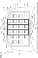
- a plurality of through-holes 15 are formed in the flange 11B of the overhanging structure 6B (unit) having the configuration described above.
- the through-holes 15 are formed for the purpose of making the inner panel 2B light in weight.
- Each through-hole 15 is formed, for example, in a rectangular shape.
- the through-holes 15 are arranged in a grid pattern. Further, the through-holes 15 are arranged in a plurality of rows (for example, four rows) in the longitudinal direction Y.
- the number of through-holes 15 in each of the two rows near the center in the longitudinal direction Y is greater than the number of through-holes 15 in the through-hole row on the front end side, and is also greater than the number of through-holes 15 in the through-hole row on the rear end side.
- a plurality of the through-holes 15 having the same shape are arranged in the longitudinal direction Y and the width direction X.
- the sealer 20B is provided on the flange 11B of the inner panel 2B.
- a portion of the sealer 20 that is in contact with both of the inner panel 2B and the outer panel 3 constitutes a joint 21B.
- a portion that is actually in contact with both of the inner panel 2B and the outer panel 3 is the joint 21B that joins these panels 2B and 3 to each other.
- all of the sealer 20B is the joint 21B.
- At least one part (in the present second modification, all) of the sealer 20B is arranged in a linear sealer region AB. At least three (in the present second modification, 23) linear sealer regions AB are provided. In the present second modification, a large number of linear sealer regions AB (AB1 to AB23) are provided.
- the direction in which the relevant linear sealer region AB1 to AB23 extends in a straight line is defined as a longitudinal direction LB.
- the longitudinal direction LB is a direction along a straight line connecting the center of one end and the center of the other end of the sealer 20B in each of the linear sealer regions AB1 to AB23.
- the longitudinal direction L of each of the linear sealer regions AB1 to AB3 is along the width direction X
- the longitudinal direction L of each of the linear sealer regions AB4 to AB23 is along the longitudinal direction Y.
- the linear sealer regions AB1 to AB3 are arranged in parallel in the longitudinal direction Y.
- the through-holes 15 are provided between the linear sealer regions AB1 and AB2.
- the through-holes 15 are provided between the linear sealer regions AB2 and AB3.
- the linear sealer regions AB4 to AB7 are adjacent to the through-holes 15 provided on the front side, at positions adjacent to the linear sealer region AB1 on the front side.
- the linear sealer regions AB8 to AB13 are arranged between the linear sealer regions AB1 and AB2, and are adjacent to the through-holes 15 in the second row from the front.
- the linear sealer regions AB14 to AB19 are arranged between the linear sealer regions AB2 and AB3, and are adjacent to the through-holes 15 in the third row from the front.
- the linear sealer regions AB20 to AB23 are adjacent to the linear sealer region AB3, and are adjacent to the through-holes 15 in the row on the rearmost side.
- the joint 21B extends continuously along the longitudinal direction L without passing through a non-joint portion.
- a region of the inner panel 2B which includes one linear sealer region AB and in which both ends in the longitudinal direction LB reach the outer circumferential edge of the inner panel 2B is defined as an end-to-end region BB.
- end-to-end region BB refers to a region of the inner panel 2B which includes a linear sealer region AB and which is aligned in the longitudinal direction L with the linear sealer region AB.
- each of the end-to-end regions BB1 to BB3 is a region of the inner panel 2B that includes the corresponding linear sealer region AB1, AB2 or AB3, and in which both ends in the longitudinal direction LB of the relevant linear sealer region AB1, AB2 or AB3 reach the outer circumference of the inner panel 2B.
- the pair of end portions of each of the end-to-end regions BB1 to BB3 are positioned at the left edge and the right edge, respectively, of an automobile hood 1B.
- the pair of end portions of each of the end-to-end regions BB4 to BB23 are positioned at the front edge and the rear edge, respectively, of the automobile hood 1B.
- each of the three longest linear sealer regions AB1 to AB3 among the plurality of linear sealer regions AB1 to AB23 has a length that is 40% or more of the length of the corresponding end-to-end region BB1, BB2 or BB3 to which the relevant linear sealer region AB1, AB2 or AB3 itself belongs.
- the proportion of the length with respect to the length of the corresponding end-to-end region BB1, BB2 or BB3 in the corresponding longitudinal direction LB1, LB2 or LB3 is 40% or more. More specifically, in plan view, the proportion of the length of the linear sealer region AB1 with respect to the length of the end-to-end region BB1 is 40% or more, and a similar situation applies with respect to the linear sealer regions AB2 and AB3.
- the lengths of the linear sealer regions AB other than the three longest linear sealer regions AB in lengths in the longitudinal direction LB among the linear sealer regions AB1 to AB3 are not particularly defined except for the point that the lengths are shorter than the lengths of the linear sealer regions AB1 to AB3.
- end-to-end regions BB1 to BB3 of the aforementioned three longest linear sealer regions AB1 to AB3 each extend in the width direction X, and do not intersect with each other within the region surrounded by the outer circumferential edge of the inner panel 2B.
- the efficiency of the operation for joining the inner panel 2B and the outer panel 3 can be further increased while making the joining strength with which the inner panel 2B and the outer panel 3 are joined to each other sufficiently high.
- the joint 21B extends continuously along the corresponding longitudinal direction LB. According to this configuration, the joining strength between the inner panel 2B and the outer panel 3 can be sufficiently secured with a smaller amount of the sealer 20B.
- the shape of the through-hole 15 may be a polygonal shape other than a rectangular shape, may be a circular shape, or may be an elliptical shape.
- Figure 15 is a plan view of the inner panel 2B of the automobile hood 1 in an example in which reinforcing sealers are provided in the second modification.
- reinforcing sealers 30B to 33B are additionally provided.
- the reinforcing sealers 30B to 33B are provided in order to, in joints 21B of the linear sealer regions AB1 to AB3, connect together end portions which are not in contact with another linear sealer region.
- the linear sealer regions AB1, AB2 and AB3 have end portions 21aB, 21bB, and 21cB, respectively, each of which is arranged at an endmost portion on one side (the left side) in the longitudinal direction LB of the corresponding linear sealer region AB1, AB2 or AB3.
- linear sealer regions AB1, AB2 and AB3 have end portions 21dA, 21eB, and 21fB, respectively, each of which is arranged at an endmost portion on the other side (the right side) in the longitudinal direction LB of the corresponding linear sealer region AB1, AB2 or AB3.
- the reinforcing sealers 30B to 33B connect together the end portions 21aB to 21fB of the plurality of the linear sealer regions AB1, AB2 and AB3 with longitudinal directions LB different from each other. Further, in the present modification, the reinforcing sealers 30B to 33B are joined to both of the inner panel 2B and the outer panel 3 to form the joints 21B.
- the reinforcing sealer 30B connects together the end portions 21aB and 21bB of the linear sealer regions AB1 and AB2 that are adjacent.
- the reinforcing sealer 31B connects together the end portions 21bB and 21cB of the linear sealer regions AB2 and AB3 that are adjacent.
- the reinforcing sealer 32B connects together the end portions 21fB and 21eB of the linear sealer regions AB3 and AB2 that are adjacent.
- the reinforcing sealer 33B connects together the end portions 21eB and 21dB of the linear sealer regions AB2 and AB1 that are adjacent.
- each of the reinforcing sealers 30B to 33B extends in a direction that intersects with each of the longitudinal directions LB of the corresponding adjacent two linear sealer regions AB.
- the reinforcing sealers 30B to 33B cooperate with the sealers 20B of a plurality of linear sealer regions to form an annular sealer 40B.
- the outer circumference of the annular sealer 40B is formed by the linear sealer region AB1, the reinforcing sealers 30B and 31B, the linear sealer region AB3, and the reinforcing sealers 32B and 33B.
- the reinforcing sealers 30B to 33B are provided that connect together the end portions 21aB to 21fB of the plurality of linear sealer regions AB1 to AB3 with longitudinal directions LB different from each other.
- a state is not entered in which the joints 21B are abruptly discontinued at the end portions 21aB to 21fB. If a state is entered in which the joints 21B are abruptly discontinued at the end portions 21aB to 21fB, a change in the strength of the outer panel 3 in the vicinity of the end portions 21aB to 21fB will be large.
- the reinforcing sealers 30B to 33B cooperate with the linear sealer regions AB1 and AB3 to form the annular sealer 40B. According to this configuration, high dent resistance can be secured at the outer circumferential side portion of the outer panel 3. Further, by applying the reinforcing sealers 30B to 33B in an annular shape, the time required for applying the reinforcing sealers 30B to 33B can be further shortened.
- the respective reinforcing sealers 30B to 33B need not be directly connected to the adjacent linear sealer regions A which the reinforcing sealers 30B to 33B connect, and there may be a gap of about several tens of mm or less therebetween.
- a part of the annular sealer 40B may be interrupted.
- a sealer having a dotted-line shape may be formed by a midway portion of the sealer being interrupted.
- the sealer having a dotted-line shape may be a sealer consisting of two sections, or may be a sealer consisting of three or more sections.
- linear sealer regions AB1' to AB3' may extend along the longitudinal direction Y.
- linear sealer regions AB1' to AB4' are provided at intervals in the width direction X.
- Figure 17 is a plan view of the inner panel 2B of the automobile hood 1 in an example where reinforcing sealers are provided in the modification of the second modification.
- reinforcing sealers 30B' to 35B' are additionally provided.
- the reinforcing sealers 30B' to 35B' are provided in order to, in the joints 21B of the linear sealer regions AB1' to AB4', connect together end portions which are not in contact with another linear sealer region.
- the linear sealer regions AB1', AB2', AB3', and AB4' have end portions 21aB' to 21dB', each of which is arranged at an endmost portion on one side (front side) in the longitudinal direction LB of the corresponding linear sealer region AB1', AB2', AB3', or AB4'.
- linear sealer regions AB1', AB2', AB3', and AB4' have end portions 21eB' to 21hB', each of which is arranged at an endmost portion on the other side (rear side) in the longitudinal direction LB of the corresponding linear sealer region AB1', AB2', AB3', or AB4'.
- the reinforcing sealers 30B' to 35B' connect together the end portions 21aB' to 21hB' of the plurality of the linear sealer regions AB1' to AB4' with longitudinal directions LB different from each other. Further, in the present modification, the reinforcing sealers 30B' to 35B' are joined to both of the inner panel 2B and the outer panel 3 to form the joints 21B.
- the reinforcing sealer 30B' connects together the end portions 21aB' and 21bB' of the linear sealer regions AB1' and AB2' that are adjacent.
- the reinforcing sealer 31B' connects together the end portions 21bB' and 21cB' of the linear sealer regions AB2' and AB3' that are adjacent.
- the reinforcing sealer 32B' connects together the end portions 21cB' and 21dB' of the linear sealer regions AB3' and AB4' that are adjacent.
- the reinforcing sealer 33B' connects together the end portions 21hB and 21gB of the linear sealer regions AB4' and AB3' that are adjacent.
- the reinforcing sealer 34B' connects together the end portions 21gB' and 21fB' of the linear sealer regions AB3' and AB2' that are adjacent.
- the reinforcing sealer 35B' connects together the end portions 21fB' and 21eB' of the linear sealer regions AB2' and AB1' that are adjacent.
- each of the reinforcing sealers 30B' to 35B' extends in a direction that intersects each of the longitudinal directions LB of the corresponding adjacent two linear sealer regions AB'.
- the reinforcing sealers 30B' to 35B' cooperate with the sealers 20B of a plurality of linear sealer regions to form an annular sealer 40B'.
- the outer circumference of the annular sealer 40B' is formed by the linear sealer region AB1', the reinforcing sealers 30B' to 32B', the linear sealer region AB4', and the reinforcing sealers 33B' to 35B'.
- inner panels 2, 2A, and 2B and the outer panel 3 are formed using steel sheets.
- the inner panels 2, 2A, and 2B and the outer panel 3 need not be formed of steel sheets.
- the inner panel 2 and the outer panel 3 may be formed of a metal material such as an aluminum alloy or a magnesium alloy, or a resin material including glass fiber or carbon fiber or the like. Further, the inner panel 2 and the outer panel 3 may be formed of a composite material of a metal material and a resin material or the like.
- the present invention can be widely applied as an automobile hood.
Landscapes
- Engineering & Computer Science (AREA)
- Mechanical Engineering (AREA)
- Chemical & Material Sciences (AREA)
- Combustion & Propulsion (AREA)
- Transportation (AREA)
- Superstructure Of Vehicle (AREA)
Abstract
Description
- The present invention relates to an automobile hood.
-
Patent Document 1 discloses a hood panel for a vehicle. The principle purpose of the hood panel is to reduce the degree of injury to a pedestrian if the pedestrian collides with the hood panel. -
Patent Document 2 discloses a hood for an automobile as exterior equipment for an automobile. The principle purpose of the hood for an automobile is to absorb the energy of contact when a pedestrian comes into contact with the hood for an automobile, by only deforming by a small amount in the inward direction of the automobile. -
- Patent Document 1:
JP2005-193863A - Patent Document 2:
JP2017-1553A - In the automobile hood disclosed in
Patent Document 1, an inner panel and an outer panel are joined using an adhesive. Mastic sealers and the like are known as adhesives for joining an inner panel and an outer panel. When assembling an automobile hood, for example, a mastic sealer is applied to the outer panel, and next, by superposing the inner panel and the outer panel on each other, the mastic sealer is sandwiched between the inner panel and the outer panel. By this means, the inner panel and the outer panel are joined to each other through the mastic sealer. - The operation to apply the mastic sealer to the outer panel is performed, for example, by a robot arm that holds a nozzle to which the sealer is supplied. From the viewpoint of shortening the time required for the application process through efficient application of the mastic sealer, the operation to apply the mastic sealer that is performed by the robot arm is preferably performed while moving the nozzle along the simplest possible path. On the other hand, if the amount of mastic sealer is reduced in order to shorten the time required for the operation to apply the mastic sealer, the strength with which the inner panel supports the outer panel will be lowered.
- In both
Patent Document 1 andPatent Document 2, there is no particular disclosure regarding a configuration for efficiently applying an adhesive such as a mastic sealer. - One objective of the present invention is, with respect to an automobile hood, to enable an increase in the efficiency of an operation for joining an inner panel and an outer panel while making the joining strength with which the inner panel and the outer panel are joined to each other sufficiently high.
- The gist of the present invention is an automobile hood which is described hereunder.
- (1) An automobile hood, including:
- an inner panel,
- an outer panel,
- a sealer, and
- a joint that, in the sealer, is a portion which joins the inner panel and the outer panel,
- wherein:
- a direction in which a linear sealer region in which the sealer is continuously arranged linearly extends is defined as a longitudinal direction;
- a region of the inner panel that is a region which includes the linear sealer region and in which both ends in the longitudinal direction reach an outer circumference of the inner panel is defined as an end-to-end region;
- at least three of the linear sealer regions are provided at intervals in at least one of a front-rear direction of the automobile hood and a width direction of the automobile hood;
- each of three longest linear sealer regions among the plurality of linear sealer regions has a length that is 40% or more of a length of the end-to-end region to which the linear sealer region itself belongs, and the joint is formed therein; and
- three end-to-end regions that include the three longest linear sealer regions among the plurality of linear sealer regions do not intersect with each other within a region that is surrounded by an outer circumferential edge of the inner panel.
- (2) The automobile hood according to the above (1), wherein the length is a length when the automobile hood is seen in plan view.
- (3) The automobile hood according to the above (1) or the above (2), wherein, in at least one of the plurality of linear sealer regions, the joints are intermittently arranged in the longitudinal direction.
- (4) The automobile hood according to any one of the above (1) to the above (3), wherein, in at least one of the plurality of linear sealer regions, the joint extends continuously along the longitudinal direction.
- (5) The automobile hood according to any one of the above (1) to the above (4), wherein at least one pair of linear sealer regions among the plurality of the linear sealer regions are arranged in parallel with each other.
- (6) The automobile hood according to any one of the above (1) to the above (5), wherein:
- the inner panel includes a unit,
- the unit includes a flange that is arranged adjacent to the outer panel, an inclined wall that extends from the flange so as to separate from the outer panel, and a bottom portion that is continuous with the inclined wall and is separated from the flange; and
- in at least one of the plurality of linear sealer regions, the joint is provided on the flange.
- (7) The automobile hood according to the above (6), wherein:
- the flange of the unit is formed in an annular shape; and
- in at least one of the plurality of linear sealer regions, all of the joints are arranged at places that are offset from a center of the annular-shaped flange.
- (8) The automobile hood according to the above (6) or the above (7), wherein:
- a plurality of the units are provided in the inner panel, and
- in at least one of the plurality of linear sealer regions, the joint is provided on the flange in each of a plurality of the units.
- (9) The automobile hood according to any one of the above (6) to the above (8), wherein a plurality of the units having the same shape are arranged in the front-rear direction and the width direction of the automobile hood.
- (10) The automobile hood according to any one of the above (1) to the above (9), wherein:
- the sealer includes a reinforcing sealer,
- the linear sealer region includes an end portion joint that is arranged at an endmost portion in the longitudinal direction among the joints of the linear sealer region, and
- the reinforcing sealer connects together end portions of the end portion joints of the plurality of linear sealer regions in which the longitudinal directions are different.
- (11) The automobile hood according to the above (10), wherein the reinforcing sealer cooperates with the sealers of the plurality of linear sealer regions to form an annular sealer.
- (12) The automobile hood according to any one of the above (1) to the above (11), wherein the inner panel is a steel sheet panel having a thickness of 0.25 mm to 0.80 mm, or is an aluminum alloy panel having a thickness of 0.40 mm to 1.20 mm.
- (13) The automobile hood according to any one of the above (1) to the above (12), wherein the outer panel is a steel sheet panel having a thickness of 0.25 mm to 0.80 mm, or is an aluminum alloy panel having a thickness of 0.40 mm to 1.20 mm.
- (14) The automobile hood according to any one of the above (1) to the above (13), wherein:
- in three longest linear sealer regions, a portion of the sealer that is separated from either one of the inner panel and the outer panel is a non-joint portion; and
- in each of the three longest linear sealer regions, the joint and the non-joint portion are alternately arranged in the longitudinal direction.
- According to the present invention, the efficiency of an operation for joining an inner panel and an outer panel in an automobile hood can be increased while making the joining strength with which the inner panel and the outer panel are joined to each other sufficiently high.
-
- [
Figure 1] Figure 1 is a schematic exploded perspective view of an automobile hood according to one embodiment of the present invention, in which diagrammatic representation of a sealer is omitted. - [
Figure 2] Figure 2 is a plan view of an inner panel of the automobile hood. - [
Figure 3] Figure 3 is a schematic cross-sectional view along a line III-III inFigure 2 . - [
Figure 4] Figure 4 is a cross-sectional view along a line IV-IV inFigure 2 , in which illustration of a portion that appears to the rear of the cross-section is omitted. - [
Figure 5] Figure 5 is a view in which one part ofFigure 3 is enlarged. - [
Figure 6] Figure 6 is a plan view in which one part of the inner panel illustrated inFigure 2 is enlarged. - [
Figure 7] Figure 7 is a perspective view in which one part of the inner panel is enlarged. - [
Figure 8] Figure 8 is a plan view of an inner panel of an automobile hood in a modification in which reinforcing sealers are provided in the embodiment. - [
Figure 9] Figure 9 is a schematic plan view of an inner panel and sealers pertaining to a first modification. - [
Figure 10] Figure 10 is a cross-sectional view along a line X-X inFigure 9 . - [
Figure 11] Figure 11 is a plan view of an inner panel of an automobile hood in a modification in which reinforcing sealers are provided in the first modification. - [
Figure 12] Figure 12 is a plan view of the inner panel of the modification of the first modification. - [
Figure 13] Figure 13 is a plan view of the inner panel of the automobile hood in an example in which reinforcing sealers are provided in the modification of the first modification. - [
Figure 14] Figure 14 is a plan view of an inner panel pertaining to a second modification of the present invention. - [
Figure 15] Figure 15 is a plan view of an inner panel of an automobile hood in an example in which reinforcing sealers are provided in the second modification. - [
Figure 16] Figure 16 is a plan view of an inner panel of a modification of the second modification. - [
Figure 17] Figure 17 is a plan view of the inner panel of the automobile hood in an example in which reinforcing sealers are provided in the modification of the second modification. - Hereunder, first, the circumstances leading to the conception of the present invention will be described, and then an embodiment will be described in detail.
- Generally, in an automobile hood, the outer panel is a relatively flat shape, while on the other hand the inner panel is a shape having unevenness. Further, a sealer such as a mastic sealer is applied at places in the inner panel that are convex toward the outer panel side. The sealer contacts the inner panel and the outer panel and joins these panels together. Further, in the automobile hood, the height (thickness) in the vehicle height direction is less than the length in the vehicle length direction and the length in the vehicle width direction of the automobile. Therefore, when the sealer is to be applied to the outer panel or inner panel during assembling of the automobile hood, the amount of movement of a nozzle for applying the sealer in the directions (vehicle length direction and vehicle width direction) that are orthogonal to the thickness direction of the automobile hood influences the time taken to perform the sealer application operation. Hence, taking into consideration the magnitude of the influence on the total movement length of a nozzle for applying sealer during production of one automobile hood, the present inventors conceived of devising a suitable layout for sealer by taking a long region of sealer as a target, which is a region that easily contributes to shortening the sealer application time. As a result, the present invention has been conceived. Hereunder, one example of the present invention is specifically described.
- Hereunder, an embodiment of the present invention is described while referring to the accompanying drawings.
-
Figure 1 is a schematic exploded perspective view of anautomobile hood 1 according to one embodiment of the present invention, in which diagrammatic representation of asealer 20 is omitted.Figure 2 is a plan view of aninner panel 2 of theautomobile hood 1.Figure 3 is a schematic cross-sectional view along a line III-III inFigure 2 .Figure 4 is a cross-sectional view along a line IV-IV inFigure 2 , in which illustration of a portion that appears to the rear of the cross-section is omitted. Note that, inFigure 3 andFigure 4 , anouter panel 3 that does not appear inFigure 2 is indicated by a chain double-dashed line that is a virtual line. -
Figure 5 is view in which one part ofFigure 3 is enlarged.Figure 6 is a plan view in which one part of theinner panel 2 shown inFigure 2 is enlarged.Figure 7 is a perspective view in which one part of theinner panel 2 is enlarged. Hereinafter, unless otherwise noted, the embodiment will be described with reference toFigure 1 to Figure 7 as appropriate. - The
automobile hood 1 is a front hood provided at the front part of an automobile, and is also called a "bonnet". An automobile in which theautomobile hood 1 is provided is, for example, a passenger vehicle. A sedan-type passenger vehicle, a coupe-type passenger vehicle, a hatchback-type passenger vehicle, a minivan-type passenger vehicle, an SUV (Sport Utility Vehicle) type passenger vehicle and the like can be mentioned as examples of the passenger vehicle. - Note that, in the present description, the terms "front", "rear", "left", "right", and "upper" and "lower" are used taking a time when the
automobile hood 1 is mounted to an automobile and theautomobile hood 1 is closed as the basis. The term "front" refers to the direction in which the automobile advances. The term "rear" refers to the direction in which the automobile reverses. The term "right" refers to the turning direction of the automobile when the automobile which is advancing turns to the right. The term "left" refers to the turning direction of the automobile when the automobile which is advancing turns to the left. Further, in the present embodiment, the vehicle width direction of the automobile to which theautomobile hood 1 is mounted is referred to as "width direction X". Further, the vehicle length direction of the automobile to which theautomobile hood 1 is mounted is referred to as "longitudinal direction Y". Furthermore, the vehicle height direction of the automobile to which theautomobile hood 1 is mounted is referred to as "height direction Z". - The
automobile hood 1 has theinner panel 2, theouter panel 3 that is supported by theinner panel 2,sealers 20 provided between theinner panel 2 and theouter panel 3, joints 21 which are portions of thesealers 20 which contact theouter panel 3 and theinner panel 2 and which are portions that join thepanels non-joint portions 22 as portions of thesealers 20 that are separated from either one of theinner panel 2 and theouter panel 3. Note that, inFigure 2 andFigure 6 , thesealers 20 are illustrated using thick lines. - In the
automobile hood 1, theouter panel 3 is a portion that constitutes a part of the outer surface of the automobile. Theouter panel 3 is formed of, for example, a metal material such as a mild steel sheet or a high-tensile strength steel sheet. Examples of the high-tensile strength steel sheet that can be mentioned include steel sheets having a tensile strength of 340 MPa or more, for example, a steel sheet having a tensile strength of 590 MPa or more. Theouter panel 3 is formed, for example, by subjecting a single steel sheet to press working or the like. In a case where theouter panel 3 is a steel sheet panel, the sheet thickness of theouter panel 3 is, for example, 0.25 mm to 0.80 mm. Theouter panel 3 may be an aluminum alloy sheet. In a case where theouter panel 3 is an aluminum alloy panel, the sheet thickness of theouter panel 3 is, for example, 0.40 mm to 1.20 mm. There are no particular restrictions with regard to the shape of theouter panel 3. Note that, in the present embodiment, theouter panel 3 has a shape in which the central portion is upwardly convex in the height direction Z. - The
inner panel 2 reinforces theouter panel 3 by being joined to anundersurface 3a of theouter panel 3 using thesealers 20. By this means, theinner panel 2 increases the panel rigidity of theouter panel 3. Theinner panel 2 is formed, for example, of a metal material such as a steel sheet. Theinner panel 2 is formed, for example, by subjecting a single steel sheet to press working. Theinner panel 2 may be an integrally formed product, or may be formed by joining a plurality of members together. In the present embodiment, theinner panel 2 is an integrally formed product. In a case where theinner panel 2 is a steel sheet panel, the sheet thickness of the inner panel 2 (thickness of the steel sheet) is, for example, 0.25 mm to 0.80 mm. The sheet thickness of theinner panel 2 may be less than the sheet thickness of theouter panel 3, may be the same as the sheet thickness of theouter panel 3, or may be greater than the sheet thickness of theouter panel 3. Note that, theinner panel 2 may be an aluminum alloy sheet. In a case where theinner panel 2 is an aluminum alloy panel, the sheet thickness of theinner panel 2 is, for example, 0.40 mm to 1.20 mm. - The
inner panel 2 has an outercircumferential portion 4 in which acontour forming portion 5 is provided, and an overhangingstructure 6 arranged so as to be surrounded by thecontour forming portion 5. - The outer
circumferential portion 4 is an outer circumferential part of theinner panel 2. When theouter panel 3 closes the engine room, the outercircumferential portion 4 of theinner panel 2 is received by the automobile body (not illustrated) together with the outer circumferential portion of theouter panel 3. By this means, a load that acts on anupper face 3b of theouter panel 3 is received by the automobile body through theinner panel 2. - The
contour forming portion 5 of the outercircumferential portion 4 is a three-dimensionally shaped portion formed at the outer circumferential part of theinner panel 2, and is a portion at which the bending rigidity is enhanced among the entire outercircumferential portion 4 of theinner panel 2. In the present embodiment, thecontour forming portion 5 is formed over the entire area in the circumferential direction of the outer circumferential portion of theinner panel 2. Note that, thecontour forming portion 5 may be formed only at one part in the circumferential direction of the outercircumferential portion 4 of theinner panel 2. Thecontour forming portion 5 includes a portion that rises and falls in the height direction Z when moved in the horizontal direction over theinner panel 2. The overhangingstructure 6 is arranged so as to be surrounded by thecontour forming portion 5. - The overhanging
structure 6 has a three-dimensional structure which is provided in order to receive a load acting on theupper face 3b of theouter panel 3. The overhangingstructure 6 has a configuration in which members that have a hat-shaped cross section (a V-shaped cross section or a U-shaped cross section) are combined. - The overhanging
structure 6 has a plurality ofincomplete units 8 that are adjacent to an inner circumferential edge portion 4a of the outercircumferential portion 4 and continuous with the outercircumferential portion 4, and a plurality ofunits 9. - The
unit 9 which is adjacent to the outercircumferential portion 4 of theinner panel 2 is connected to the outercircumferential portion 4 directly or through theincomplete unit 8. - The
incomplete unit 8 has a configuration equivalent to a configuration in which one portion of theunit 9 has been cut off along the circumferential direction of the polygonal (in the present embodiment, hexagonal)unit 9. Theincomplete unit 8 has a side portion that is similar to asub-unit 10 of theunit 9 that is described later. The side portion is continuous with the inner circumferential edge portion 4a of the outercircumferential portion 4. - Although a configuration may be adopted in which only one
unit 9 is provided, in the present embodiment a plurality of theunits 9 are provided. Eachunit 9 is formed in a polygonal (in the present embodiment, hexagonal) annular shape in plan view in the height direction Z. Hereinafter, when simply the term "plan view" is used, it means a plan view in the height direction Z. By forming eachunit 9 in a small annular shape (in the present embodiment, a polygonal annular shape), theinner panel 2 can be made lightweight and theinner panel 2 can also be provided with high rigidity. - In the present embodiment, each
unit 9 is formed in the shape of a substantially regular hexagon with rounded corners. The term "regular hexagon" means a hexagon in which the lengths of the respective sides are equal and the interior angles are also a constant angle of 120 degrees. Further, in the present description, the term "substantially regular hexagon" refers to a hexagon that can be treated as a regular hexagon. Therespective units 9 are formed so that the shape of eachunit 9 is substantially the same. Note that, the term "substantially the same" in this case indicates that the configuration is the same except in the respect that the shape of eachunit 9 is caused to match a shape which matches the curved shape of theouter panel 3. - Each
unit 9 may also be formed in the shape of a hexagon that is other than a regular hexagon. Examples of a hexagon other than a regular hexagon that can be mentioned include a hexagon in which the lengths of the respective sides are not uniform, and a hexagon in which the interior angles are not uniform at 120 degrees. Examples of a hexagon in which the lengths of the respective sides are not uniform that can be mentioned include a hexagon in which the length of a front end side and the length of a rear end side are set to a predetermined first length, and which has four sides, lengths of which are each set to a predetermined second length that is different from the first length. - The overhanging
structure 6 has a structure in which a plurality of theunits 9 having a hexagonal annular shape are disposed in a close-packed arrangement. In this case, the term "close-packed" means that a plurality of theunits 9 that are adjacent to each other are arranged without a gap therebetween. Specifically, eachunit 9 is partitioned off from theother units 9 byunit boundaries 14. As illustrated inFigure 5 , afront end 13c (lower end) of abottom portion 13 forms a boundary of thebottom portion 13 that includes thefront end 13c, to thereby form theunit boundary 14. Theunit boundary 14 is formed in a hexagonal shape in plan view. By having such a structure in which theunits 9 are disposed in a close-packed hexagonal arrangement, the overhangingstructure 6 can withstand loads in substantially the same manner from all directions including the height direction Z over the whole area in plan view. - In a case where
flanges 11, described later, of theunits 9 are disposed in a close-packed arrangement, preferably a plurality of theunits 9 have the same shape. Further, theunits 9 that have similar forms to each other and have differing shapes may be disposed in a close-packed arrangement. Note that, in the overhangingstructure 6, theunits 9 need not be disposed in a close-packed arrangement, and another portion may be formed between theunits - In the present embodiment, the plurality of the
units 9 are formed symmetrically in the width direction X as a whole. For example, in the present embodiment, three of theunits 9 are arranged side by side in the front-to-rear direction at the center in the width direction X. Note that, there is no constraint on the direction of theunits 9. - In the present embodiment, in the direction toward the right side from the aforementioned three
units 9 arranged at the central position in the width direction X are provided, in the following order, fourunits 9 which are arranged side by side in the longitudinal direction Y, a further threeunits 9 which are arranged side by side in the longitudinal direction Y, a further twounits 9 which are arranged side by side in the longitudinal direction Y, and a further twounits 9 which are arranged side by side in the longitudinal direction Y. Furthermore, similarly to the foregoing arrangement, in the direction toward the left side from the aforementioned threeunits 9 arranged at the central position in the width direction X are provided, in the following order, fourunits 9 which are arranged side by side in the longitudinal direction Y, a further threeunits 9 which are arranged side by side in the longitudinal direction Y, a further twounits 9 which are arranged side by side in the longitudinal direction Y, and a further twounits 9 which are arranged side by side in the longitudinal direction Y. Thus, a plurality of theunits 9 having the same shape are arranged in the longitudinal direction Y (front-rear direction) and the width direction X. - As illustrated clearly in
Figure 5 andFigure 6 , each of theunits 9 has six of the sub-units 10 (10a to 10f). In the present embodiment, in each of theunits 9, afront sub-unit 10a and arear sub-unit 10d extend along the width direction X, respectively. Further, in each of theunits 9, the remaining foursub-units 10 extend in a direction that inclines with respect to the longitudinal direction Y in plan view. Theunit 9 that has a polygonal shape is formed by the plurality ofsub-units 10 in this way. - Each of the sub-units 10 (10a to 10f) has a
flange 11, aninclined wall 12 continuous with theflange 11, and thebottom portion 13 that is continuous with theinclined wall 12 and is separated from theflange 11. - The
flange 11 is adjacent to theouter panel 3, and in the sub-unit 10, theflange 11 is a portion that is arranged closest to theouter panel 3. Theflange 11 is a strip-shaped portion. In asingle unit 9, outer circumferential portions of theflanges 11 of the six sub-units 10a to 10f form a hexagonal flange as a whole. Thus, in the present embodiment, in asingle unit 9, the plurality offlanges 11 are formed in an annular shape as a whole. Note that, the outer circumferential portions of theflanges 11 of the six sub-units 10a to 10f may, as a whole, form a flange having a polygonal shape other than a hexagon, and may form a substantially circular flange, or may form a flange having a substantially oval shape. Further,inner end portions 11a of the sixflanges 11 constitute an annular end portion which is centered on the center of theannular unit 9 as a whole. In the present embodiment, because theinner end portion 11a of eachflange 11 is formed in an arc shape which is centered on the center of theunit 9, theinner end portions 11a of the sixflanges 11 are formed in a circular shape as a whole. - Note that, the
inner end portions 11a of the sixflanges 11 may be formed in a polygonal shape as a whole, or may be formed in an elliptical shape as a whole. In the present embodiment, the plurality offlanges 11 in the plurality ofunits 9 are disposed in a close-packed arrangement. In anupper face 11b of theflange 11, a width to which a joint 21 can be applied is preferably 2 mm or more from the viewpoint that a sufficient amount of the joint 21 can be provided. - Each of the two end portions of the
flange 11 in the longitudinal direction is formed in a curved shape in plan view, and smoothly connects with theflange 11 of anadjacent sub-unit 10. In the present embodiment, in eachunit 9, theflanges 11 of at least some of the sub-units 10 are adhered to the joint 21 at theupper face 11b, and are adhered to theouter panel 3 through the joint 21. Theinclined wall 12 extends downward from theflange 11. - The
inclined wall 12 is disposed between theflange 11 and thebottom portion 13, and connects theflange 11 and thebottom portion 13. Theinclined wall 12 extends from theflange 11 so as to separate from theouter panel 3. Theinclined wall 12 is provided over the entire area in a longitudinal direction L of the sub-unit 10 in which theinclined wall 12 in question is provided. Theinclined wall 12 is formed, for example, in a tapered shape that advances toward the central axis side (theinner end portion 11a side) of theunit 9 as it approaches theouter panel 3 side. - The
flange 11 is continuous with the upper end of theinclined wall 12. Thebottom portion 13 is continuous with the lower end of theinclined wall 12. In theunit 9, thebottom portion 13 is a portion that is farthest from theouter panel 3, and is separated from theflange 11. Thebottom portion 13 is formed in a curved shape which is convex in the downward direction. Thebottom portion 13 is provided over the entire area in the longitudinal direction of the sub-unit 10 in which theinclined wall 12 in question is provided. Theflange 11, theinclined wall 12, and thebottom portion 13 are arranged in that order from the inner side to the outer side in the radial direction of theunit 9. Thefront end 13c of thebottom portion 13 in oneunit 9 is integral with thefront end 13c of thebottom portion 13 in anotherunit 9 that is adjacent thereto. - Next, the
sealer 20 will be described more specifically while referring mainly toFigure 2 ,Figure 5 andFigure 6 . Thesealer 20 is provided for joining theinner panel 2 and theouter panel 3. In the present embodiment, thesealer 20 is an adhesive. A mastic sealer (mastic adhesive) can be exemplified as the adhesive. A resin-based adhesive can be exemplified as the mastic sealer. The adhesive may have a property of being cured at normal temperature (for example, 20 degrees Celsius), or may have a property of being cured by undergoing a heating process or a drying process. - The
sealer 20 is arranged so as to secure the bonding strength between theinner panel 2 and theouter panel 3 while achieving a reduction in the weight of theautomobile hood 1. In the present embodiment, thesealer 20 is provided in eachunit 9 of theinner panel 2. In the present embodiment, the width of the sealer 20 (the dimension of thesealer 20 in the direction orthogonal to the extending direction of thesealer 20 in plan view) is about 5 mm to 25 mm. A portion of thesealer 20 that is in contact with both of theinner panel 2 and theouter panel 3 constitutes a joint 21. Specifically, in thesealer 20, a portion that is actually in contact with both of theinner panel 2 and theouter panel 3 is the joint 21 that joins thesepanels upper face 11b of theflange 11 and theundersurface 3a of theouter panel 3. Thus, by theflange 11 of theinner panel 2 that is a flange which projects to theouter panel 3 side being joined to theouter panel 3 through the joint 21, theinner panel 2 can support theouter panel 3 with high rigidity. - At least one part of the sealer 20 (in the present embodiment, all of the sealer 20) is arranged in a linear sealer region A. The term "linear sealer region A" refers to a region in which the
sealer 20 is continuously provided and extends in a linear shape. The term "linear shape" in this case is not limited to the case of a true straight line, and also includes a case where thesealer 20 meanders or curves within a range of about three times the width of thesealer 20 in a direction orthogonal to the longitudinal direction of thesealer 20 in plan view. At least three (in the present embodiment, nine) of the linear sealer regions A are provided. In the present embodiment, the linear sealer regions A (A1 to A9) are provided. In the present embodiment, a place where thesealer 20 is provided is a sealer region (linear sealer region A). - In each of the linear sealer regions A1 to A9, the direction in which the relevant linear sealer region A1 to A9 extends is defined as a longitudinal direction L (L1 to L9). The longitudinal direction L is a direction on a straight line connecting the center of one end and the center of the other end of the
sealer 20 in each linear sealer region A. In the present embodiment, the respective longitudinal directions L1 to L6 of the linear sealer regions A1 to A6 are directions that extend from the lower left to the upper right in plan view, the longitudinal direction L7 of the linear sealer region A7 is a direction along the width direction X, and the respective longitudinal directions L8 and L9 of the linear sealer regions A8 and A9 are directions from the lower left to the upper right. Although inFigure 2 the longitudinal directions L1 to L6 are indicated collectively, they are different directions to each other. - In the present embodiment, the linear sealer region A1 is arranged at the left end of the linear sealer regions A1 to A9. Further, the linear sealer regions A1 to A6 which are parallel to each other are arranged from the left side to the right side. The linear sealer region A7 is continuous with the front end of the linear sealer region A1, and in addition, the linear sealer regions A7 and A8 are continuous with each other. Further, the linear sealer region A9 is continuous with the rear end of the linear sealer region A3.
- Each of the linear sealer regions A1 to A9 is provided within the overhanging
structure 6. The linear sealer regions A1 to A5 extend over a plurality of theunits 9. Specifically, the linear sealer region A1 extends over four of theunits 9 that are arranged in series from the lower left to the upper right. The linear sealer region A2 extends over six of theunits 9 that are arranged in series from the lower left to the upper right. The linear sealer region A3 extends over five of theunits 9 that are arranged in series from the lower left to the upper right. The linear sealer region A4 extends over five of theunits 9 that are arranged in series from the lower left to the upper right. The linear sealer region A5 extends over four of theunits 9 that are arranged in series from the lower left to the upper right. The linear sealer region A6 is arranged in one of theunits 9. Note that, the linear sealer regions A7 and A8 are arranged in theincomplete unit 8 at the front end. Further, the linear sealer region A9 is arranged in theincomplete unit 8 on the rear end side. - In the present embodiment, in each
unit 9, only one linear sealer region A is provided. Specifically, in a direction orthogonal to the longitudinal direction L of the linear sealer regions A1 to A6, the linear sealer region A is arranged only on one of a pair of end portions of eachunit 9. In other words, in the linear sealer regions A1 to A6 as at least one of the plurality of linear sealer regions, all thejoints 21 are arranged at places that are offset from the center (the center point of the circle of theinner end portions 11a) of theflanges 11. By means of the above configuration relating to thesealer 20, the total weight of thesealer 20 in theautomobile hood 1 can be reduced. - As mentioned above, each of the linear sealer regions A1 to A5 extends over a plurality of the
units 9. Therefore, each of thesealers 20 of the linear sealer regions A1 to A5 extends while rising and falling in the height direction Z. With regard to the linear sealer region A6 also, thesealer 20 extends while rising and falling in the height direction Z. Further, in thesealer 20 of each of the linear sealer regions A1 to A6, a portion that is mounted on theflange 11 constitutes the joint 21. Specifically, thejoints 21 are arranged in each of the linear sealer regions A1 to A6. In each of the linear sealer regions A1 to A5, thejoints 21 are intermittently arranged in the longitudinal direction L. In thesealer 20 of each of the linear sealer regions A1 to A5, a place that is mounted on theflange 11 constitutes the joint 21 as described above. Specifically, therespective sealers 20 of the linear sealer regions A1 to A5 formrespective joints 21 at theflanges 11 of a plurality of theunits 9. On the other hand, in thesealer 20 of each of the linear sealer regions A1 to A6, a place arranged on theinclined wall 12 or thebottom portion 13 constitutes anon-joint portion 22 which does not join theinner panel 2 and theouter panel 3 to each other. In each of the linear sealer regions A1 to A6, thejoints 21 and thenon-joint portions 22 are alternately arranged in the corresponding longitudinal direction L1 to L6. In each of the linear sealer regions A1 to A5, approximately 70% of the region is thejoints 21, and the remaining about 30% of the region is thenon-joint portions 22. In the linear sealer regions A7 to A9, a portion of thesealer 20 that is mounted on theflange 11 of theincomplete unit 8 constitutes the joint 21. Thus, in the present embodiment, the joint 21 is formed in each of the linear sealer regions A1 to A9. Note that, it suffices that the joint 21 is formed in at least three longest linear sealer regions A2, A4 and A3 among the plurality of linear sealer regions A1 to A9. - In the present embodiment, at least three of the linear sealer regions A are provided at intervals in at least one of the longitudinal direction Y as the front-rear direction of the
automobile hood 1 and the width direction X. Specifically, in the vicinity of the center of theautomobile hood 1 in the width direction X, the linear sealer region A2 is arranged diagonally to the rear of the linear sealer regions A1, A7, and A8. In addition, diagonally to the rear of the linear sealer region A2, the linear sealer regions A3, A4, and A5 are arranged in that order toward the rear. The linear sealer region A9 is arranged to the rear of the linear sealer region A3. Further, the linear sealer region A6 is arranged on the diagonally rear side of the linear sealer region A5. Thus, in the present embodiment, at least three of the linear sealer regions A are provided at intervals in both of the longitudinal direction Y and the width direction X. - In the present embodiment, a region of the
inner panel 2 which includes one linear sealer region A and in which both ends in the longitudinal direction L reach the outer circumferential edge of theinner panel 2 is defined as an end-to-end region B. In other words, a region of theautomobile hood 1 which includes one linear sealer region A and which is present along the longitudinal direction L is defined as an end-to-end region B. It can also be said that the end-to-end region B is a region of theinner panel 2 which includes the linear sealer region A and which is aligned in the longitudinal direction L with the linear sealer region A (which includes the linear sealer region A and regions aligned with the linear sealer region A). - More specifically, end-to-end regions B1 to B9 that include the linear sealer regions A1 to A9, respectively, are defined. In plan view, the end-to-end region B1 is a region of the
inner panel 2 that includes the linear sealer region A1 and in which both ends in the longitudinal direction L of the linear sealer region A1 reach the outer circumferential edge of theinner panel 2. In the present embodiment, a pair of end portions B1a and B1b of the end-to-end region B 1 are located at the left rear edge and the front edge of theinner panel 2, respectively. Similarly, in plan view, the end-to-end regions B2 to B4 are regions of theinner panel 2 that include the corresponding linear sealer regions A2 to A4 and in which both ends in the corresponding longitudinal directions L2 to L4 of the linear sealer regions A2 to A4 reach the outer circumferential edge of theinner panel 2. In the present embodiment, the respective pairs of end portions B2a and B2b, B3a and B3b, and B4a and B4b of the end-to-end regions B2 to B4 are located at the left rear edge and the front edge of theinner panel 2, respectively. Further, in plan view, the end-to-end regions B5 and B6 are regions of theinner panel 2 that include the corresponding linear sealer regions A5 and A6 and in which both ends in the corresponding longitudinal directions L5 and L6 of the linear sealer regions A5 and A6 reach the outer circumferential edge of theinner panel 2. In the present embodiment, the respective pairs of end portions B5a and B5b, and B6a and B6b of the end-to-end regions B5 and B6 are located at the rear edge and the right edge of theinner panel 2, respectively. - In the present embodiment, three longest linear sealer regions A in lengths in the longitudinal direction L among the linear sealer regions A1 to A9 are, in order of longest length, the linear sealer regions A2, A4, and A3. In plan view, the lengths of the three longest linear sealer regions A2, A4, and A3 among the plurality of linear sealer regions A are 40% or more of the lengths of the end-to-end regions B2, B4 and B3 to which the linear sealer regions A2, A4 and A3 themselves belong, respectively. Specifically, in plan view, in these longest linear sealer regions A2, A4, and A3, the proportion of the respective lengths with respect to the lengths of the corresponding end-to-end regions B2, B4 and B3 in the corresponding longitudinal directions L2 to L4 is 40% or more respectively. More specifically, in plan view, in the longitudinal direction L2, the proportion of the length of the linear sealer region A2 with respect to the length between the end portions B2a and B2b of the end-to-end region B2 is 40% or more. Further, in plan view, in the longitudinal direction L3, the proportion of the length of the linear sealer region A3 with respect to the length between the end portions B3a and B3b of the end-to-end region B3 is 40% or more. Further, in plan view, in the longitudinal direction L4, the proportion of the length of the linear sealer region A4 with respect to the length between the end portions B4a and B4b of the end-to-end region B4 is 40% or more.
- The grounds for setting the respective lengths of the three longest linear sealer regions A2, A4, and A3 among the plurality of linear sealer regions A to 40% or more of the respective lengths of the corresponding end-to-end regions B2, B4 and B3 to which the linear sealer regions A2, A4 and A3 themselves belong in this way is as follows. Specifically, in the
automobile hood 1, for reasons pertaining to the design and the design space, in a region up to a maximum of about 30% of an outer circumferential side portion of theautomobile hood 1, (1) the rigidity of theouter panel 3 is high and it is not necessary for the region to be stiffened using theinner panel 2. Alternatively, (2) it is difficult to set the linear sealer region A because it is difficult to stiffen the region using theinner panel 2 due to interference with other components. Therefore, it is possible to set the length of the sealer region A to (100% - 2×30% =) 40% or more of the length of the linear sealer region B. By forming these regions A2, A4 and A3 in a long linear shape and also providing thejoints 21 in each of these regions A2, A4 and A3, the efficiency of the operation for joining theinner panel 2 and theouter panel 3 can be increased while making the joining strength with which theinner panel 2 and theouter panel 3 are joined to each other sufficiently high. - In the present embodiment, the lengths of the linear sealer regions A other than the three longest linear sealer regions A in lengths in the longitudinal direction L among the linear sealer regions A1 to A9 are not particularly defined except for the point that the lengths are shorter than the lengths of the three longest linear sealer regions A2, A4 and A3.
- Further, in the present embodiment, the end-to-end regions B2, B4 and B3 of the aforementioned three longest linear sealer regions A2, A4 and A3 among the plurality of linear sealer regions A1 to A9 are arranged so that intersection of the end-to-end regions B2, B4 and B3 with each other is avoided (the end-to-end regions B2, B4 and B3 are separated). In the present embodiment, the end-to-end regions B2, B4 and B3 are arranged in a linear shape extending from the lower left to the upper right in plan view, and are substantially parallel to each other. Hence, the end-to-end regions B2, B4 and B3 do not intersect with each other in the region surrounded by the outer circumferential edge of the
inner panel 2. - In the present embodiment, in each
unit 9, thejoints 21 of the linear sealer regions A1 to A6 are arranged over twoflanges unit 9, thejoints 21 are arranged over theflanges 11 of the sub-units 10c and 10d. Further, only one linear sealer region A of the plurality of linear sealer regions A is passed over oneunit 9. - Further, in the present embodiment, in plan view, the
joints 21 are arranged in a well-balanced manner in theautomobile hood 1. Specifically, thejoints 21 are arranged on both sides of the center of theautomobile hood 1 in the width direction X, and are scattered in a region of at least 40% or more of the total width of theautomobile hood 1. Similarly, thejoints 21 are arranged on both sides of the center of theautomobile hood 1 in the longitudinal direction Y, and are scattered in a region of at least 40% or more of the total length of theautomobile hood 1. - When assembling the
automobile hood 1 having the configuration described above, first, theinner panel 2, theouter panel 3, and thesealer 20 are prepared. Next, theinner panel 2 or theouter panel 3 is held by a jig or the like as an application target. Next, a robot arm applies a sealer nozzle to the application target so as to apply thesealer 20 to form the arrangement illustrated inFigure 2 . Next, a robot arm or the like is used to fit together the application target and theinner panel 2 orouter panel 3 that is different from the application target. By this means, some of thesealer 20 comes into contact with both of theinner panel 2 and theouter panel 3 to form thejoints 21. Thereafter, for example, the outer circumferential edge portion of theouter panel 3 is subjected to hemming to complete theautomobile hood 1. - As described above, according to the present embodiment, the three longest linear sealer regions A2, A4 and A3 among the linear sealer regions A1 to A9 are each a length that is 40% or more of the length of the corresponding end-to-end regions B2, B4 and B3 to which the linear sealer regions A2, A4 and A3 themselves belong, respectively, and the
joints 21 are formed in these linear sealer regions A2, A4 and A3. Further, the three end-to-end regions B2, B4 and B3 that include the aforementioned three longest linear sealer regions A2, A4 and A3 do not intersect with each other within the region surrounded by the outer circumferential edge of theinner panel 2. With this configuration, an operation to apply thesealer 20 can be performed by moving the nozzle that applies thesealer 20 along a simple path. Hence, during assembly of theautomobile hood 1, the time required for the application process can be made shorter through the efficient application of thesealer 20. In particular, since thesealer 20 can be applied in long linear shapes, the movement of the robot arm when applying thesealer 20 using the robot arm can be made simpler, and the life of the robot arm can be extended through a reduction in the load on the robot arm in comparison to a case where the robot arm performs complicated movements. In addition, by making the lengths of the longest three linear sealer regions A2, A4 and A3 long and also arranging at least these three linear sealer regions A2, A4 and A3 at intervals in the longitudinal direction Y, the length of thejoints 21 can be sufficiently secured and these three linear sealer regions A2, A4, and A3 can be arranged in a well-balanced manner so as not to intersect with each other. As a result, the joining strength between theinner panel 2 and theouter panel 3 can be sufficiently secured using thejoints 21. Based on the above described configuration, for theautomobile hood 1, the efficiency of the operation for joining theinner panel 2 and theouter panel 3 can be increased while making the joining strength with which theinner panel 2 and theouter panel 3 are joined to each other sufficiently high. - Further, according to the present embodiment, in the linear sealer regions A1 to A5, the
joints 21 are intermittently arranged in the corresponding longitudinal directions L1 to L5. According to this configuration, while quickly applying thesealer 20 in straight lines, thejoints 21 can be arranged at places that are suitable for joining theinner panel 2 and theouter panel 3. - In particular, in the present embodiment, in each of the three longest linear sealer regions A2, A4 and A3, the
joints 21 and thenon-joint portions 22 are alternately arranged in the longitudinal directions L2, L4 and L3, respectively. According to this configuration, while simplifying the movement of the robot arm when applying thesealer 20 using the robot arm, thejoints 21 can be applied in a well-balanced manner to a wider area in theautomobile hood 1. Hence, the efficiency of the operation for joining theinner panel 2 and theouter panel 3 can be further increased while making the joining strength with which theinner panel 2 and theouter panel 3 are joined to each other sufficiently high. - Further, according to the present embodiment, the plurality of linear sealer regions A1 to A6 are arranged in parallel with each other. According to this configuration, the plurality of linear sealer regions A1 to A6 can be collectively formed by, for example, moving a plurality of (three) nozzles linearly two times. Hence, the operation to apply the
sealer 20 can be performed more quickly. - Further, according to the present embodiment, the
joints 21 of the linear sealer regions A1 to A5 are provided onflanges 11 of a plurality of theunits 9. According to this configuration, by performing the operation of forming one linear sealer region A which can be completed in a short time, thejoints 21 can be collectively provided on theflanges 11 of a plurality of theunits 9. In particular, in the present embodiment, a plurality of theunits 9 that have the same shape are arranged in the longitudinal direction Y and the width direction X of theautomobile hood 1. In the case of such an arrangement of theunits 9, if the configuration is one in which the long linear sealer regions A1 to A5 are provided, the efficiency of applying thesealer 20 can be made very high, and assembly of theautomobile hood 1 can be completed in a shorter time through shortening of the time required to perform the sealer application operation. - Note that, in the embodiment described above, the
sealer 20 has been described by taking as an example a form in which thesealer 20 extends from the lower left to the upper right. However, the form of thesealer 20 may be different from the form described in the above example. For example, thesealer 20 may be arranged symmetrically in the width direction X with respect to the arrangement shown inFigures 2 and6 , or may be arranged symmetrically in the longitudinal direction Y. - An embodiment of the present invention has been described above. However, the present invention is not limited to the above embodiment. In the present invention, various changes are possible within the scope of the accompanying claims. Note that, hereunder, configurations that are different from the above embodiment are mainly described, and components that are the like as in above embodiment are denoted by the like reference symbols and a detailed description thereof is omitted.
- In the embodiment described above, the left rear end (one end) of the linear sealer regions A1, A2, A4 to A6, and A9 and the right front end (other end) of the linear sealer regions A2 to A6, and A8 are each provided as a free end as an end portion that is independent from
other sealers 20. However, a different arrangement may also be adopted.Figure 8 is a plan view of theinner panel 2 of theautomobile hood 1 in a modification in which reinforcing sealers are provided in the embodiment. - In this modification, in addition to the configuration of the embodiment described above, reinforcing
sealers 30 to 39 are additionally provided. The reinforcingsealers 30 to 39 are provided to connect together end portions ofjoints 21 of the linear sealer regions A1 to A6, A8, and A9 that are end portions which are not in contact with another linear sealer region. - Specifically, the linear sealer region A1 has an
end portion 21a that is disposed on the leftmost side in an end portion joint 21 arranged at an endmost portion on one side (the left side) in the longitudinal direction L1 of the linear sealer region A1 among the plurality ofjoints 21. Similarly, the linear sealer regions A2, A4, A5, A6, and A9 haveend portions 21b to 21f that are respectively disposed on the leftmost side in an end portion joint 21 arranged at an endmost portion on one side (the left side) in the longitudinal direction L of the corresponding linear sealer region A2, A4, A5, A6 or A9. - Further, the linear sealer region A2 has an
end portion 21g that is disposed on the rightmost side in an end portion joint 21 that is arranged at an endmost portion on the other side (the right side) in the longitudinal direction L2 of the linear sealer region A2 among the plurality ofjoints 21. Similarly, the linear sealer regions A3 to A6, and A8 haveend portions 21h to 211 that are respectively disposed on the rightmost side in an end portion joint 21 arranged at an endmost portion on the other side (the right side) in the longitudinal direction L of the corresponding linear sealer region A3, A4, A5, A6, or A8. - In this modification, the reinforcing
sealers 30 to 39 connect together theend portions 21a to 21l of the end portion joints 21 of the plurality of linear sealer regions A1 to A6, A8 and A9 with longitudinal directions L different from each other. Further, in the present embodiment, by passing over at least one of theflanges 11, the respective reinforcingsealers 30 to 39 are joined to both of theinner panel 2 and theouter panel 3 to form thejoints 21. Specifically, in the reinforcingsealers 30 to 39, a place that is disposed on theflange 11 is the joint 21. - More specifically, the reinforcing
sealer 30 connects together theend portions sealer 30 is arranged on theflange 11 between the linear sealer regions A1 and A2, and this portion forms the joint 21. - The reinforcing
sealer 31 connects together theend portions sealer 31 is arranged on theflange 11 of theincomplete unit 8 between the linear sealer regions A2 and A9, and this portion forms the joint 21. - The reinforcing
sealer 32 connects together theend portions sealer 32 is arranged on theflange 11 of theincomplete unit 8 and theflange 11 of theunit 9 between the linear sealer regions A9 and A4, and this portion forms the joint 21. - The reinforcing
sealer 33 connects together theend portions sealer 33 is arranged on theflange 11 of theincomplete unit 8 and theflange 11 of theunit 9 between the linear sealer regions A4 and A5, and this portion forms the joint 21. - The reinforcing
sealer 34 connects together theend portions sealer 34 is arranged on theflange 11 of theincomplete unit 8 and theflange 11 of theunit 9 between the linear sealer regions A5 and A6, and this portion forms the joint 21. - The reinforcing
sealer 35 connects together endportions sealer 35 is arranged on theflange 11 of theunit 9 between the linear sealer regions A6 and A5, and this portion forms the joint 21. - The reinforcing
sealer 36 connects together endportions sealer 36 is arranged on theflange 11 of theincomplete unit 8 and theflange 11 of theunit 9 between the linear sealer regions A5 and A4, and this portion forms the joint 21. - The reinforcing sealer 37 connects together end
portions sealer 35 is arranged on theflange 11 of theunit 9 between the linear sealer regions A4 and A3, and this portion forms the joint 21. - The reinforcing
sealer 38 connects together endportions sealer 38 is arranged on theflange 11 of theincomplete unit 8 and theflange 11 of theunit 9 between the linear sealer regions A3 and A2, and this portion forms the joint 21. - The reinforcing
sealer 39 connects together endportions 21g and 21l of the end portion joints 21 of the linear sealer regions A2 and A8 that are adjacent. One part of the reinforcingsealer 39 is arranged on theflange 11 of theincomplete unit 8 and theflange 11 of theunit 9 between the linear sealer regions A2 and A8, and this portion forms the joint 21. - In the present embodiment, preferably each of the reinforcing
sealers 30 to 39 extends in a direction that intersects with each of the longitudinal directions L of the corresponding adjacent two linear sealer regions A. - According to the configuration described above, the reinforcing
sealers 30 to 39 cooperate with thesealers 20 of a plurality of linear sealer regions to form anannular sealer 40. The outer circumference of theannular sealer 40 is formed by the linear sealer region A1, the reinforcingsealers 30 to 34, the linear sealer region A6, the reinforcingsealers 35 to 39, and the linear sealer regions A8 and A7. - As described above, according to the present modification, the reinforcing
sealers 30 to 39 are provided that connect together theend portions 21a to 211 of the end portion joints 21 of the plurality of linear sealer regions A1 to A6, A8, and A9 with longitudinal directions L different from each other. According to this configuration, at each of theend portions 21a to 211, a state is not entered in which thejoints 21 are abruptly discontinued at theend portions 21a to 211. If a state is entered in which thejoints 21 are abruptly discontinued at theend portions 21a to 211, a change in the strength of theouter panel 3 in the vicinity of theend portions 21a to 211 will be large. In the case of such a state, there is room for improvement with respect to securing sufficient dent resistance of theouter panel 3 in the vicinity of theend portions 21a to 211. By providing the reinforcingsealers 30 to 39 that connect together theend portions 21a to 211, a change in the strength of theouter panel 3 in the vicinity of theend portions 21a to 211 can be made small, and the dent resistance of theouter panel 3 in the vicinity of theend portions 21a to 211 can be further increased. By this means, the dent resistance of theouter panel 3 as a whole can be further increased. - Further, according to the present embodiment, the reinforcing
sealers 30 to 39 cooperate with the linear sealer regions A1, A6, A7, and A8 to form theannular sealer 40. According to this configuration, high dent resistance can be secured at the outer circumferential side portion of theouter panel 3. Further, by applying the reinforcingsealers 30 to 39 in an annular shape, the time required for applying the reinforcingsealers 30 to 39 can be further shortened. - Note that, the respective reinforcing
sealers 30 to 39 need not be directly connected to the adjacent linear sealer regions A which the reinforcingsealers 30 to 39 connect, and there may be a gap of about several tens of mm or less therebetween. Further, a part of theannular sealer 40 may be interrupted. For example, in at least one of the reinforcingsealers 30 to 39, a sealer having a dotted-line shape may be formed by a midway portion of the sealer being interrupted. The sealer having a dotted-line shape may be a sealer consisting of two sections, or may be a sealer consisting of three or more sections. - In the above embodiment and modification, the
unit 9 is described using an example of theunit 9 that has a hexagonal shape. However, the unit need not have a hexagonal shape. For example, as illustrated inFigure 9 to Figure 10 , instead of the overhangingstructure 6, an overhangingstructure 6A (overhanging structure with a small frame structure) that includes a plurality ofunits 9A formed in a quadrangular shape as a polygonal shape may be provided.Figure 9 is a schematic plan view of aninner panel 2A and asealer 20A pertaining to a first modification.Figure 10 is a cross-sectional view along a line X-X inFigure 9 . The overhangingstructure 6A has a configuration in which theunits 9A are disposed in a close-packed arrangement. - In the present first modification, in plan view, each
unit 9A is formed in a rectangular shape with rounded corners. Eachunit 9A is formed in substantially the same shape. Note that in this case, the term "substantially the same" indicates that the configurations are the same except that the shape of eachunit 9A is made to conform to a shape that is matched to the curved shape of theouter panel 3. Eachunit 9A may be formed in a quadrangle other than a rectangle, such as a square. Note that, in the overhangingstructure 6A, theunits 9A need not be disposed in a close-packed arrangement, and another portion may be formed between theunits - Each of the
units 9A has four of the sub-units 10 (10a to 10d). In the present embodiment, in eachunit 9A, the sub-unit 10a and the sub-unit 10c are arranged separated from each other in the longitudinal direction Y. Further, in eachunit 9A, the sub-unit 10b and the sub-unit 10d are arranged separated from each other in the width direction X. - Each of the sub-units 10 (10a to 10d) has the
flange 11, theinclined wall 12 continuous with theflange 11, and thebottom portion 13 that is continuous with theinclined wall 12 and is separated from theflange 11. - The plurality of
flanges 11 of eachunit 9A are formed in an annular shape as a whole. In asingle unit 9A, the front ends 13c of thebottom portions 13 of the four sub-units 10 form asingle unit boundary 14A having a square shape as a whole. At theunit boundary 14A, theunits units 9A are arranged in a grid pattern. Further, theunits 9A are arranged in a plurality of rows (for example, four rows) in the longitudinal direction Y. In the present embodiment, the number ofunits 9A in each of the two unit rows near the center in the longitudinal direction Y is greater than the number ofunits 9A in the unit row ofunits 9A on the front end side, and is also greater than the number ofunits 9A in the unit row ofunits 9A on the rear end side. - Next, the
sealer 20A will be more specifically described. Thesealer 20A is provided for joining theinner panel 2A and theouter panel 3 to each other. - The
sealer 20A is provided in eachunit 9A of theinner panel 2A. A portion of thesealer 20A that is in contact with both of theinner panel 2A and theouter panel 3 constitutes a joint 21A. Specifically, in thesealer 20A, portions that are actually in contact with both of theinner panel 2A and theouter panel 3 arejoints 21A that join thesepanels - At least one part (in the present embodiment, all) of the
sealer 20A is arranged in a linear sealer region AA. At least three (in the present embodiment, four) linear sealer regions AA are provided. In the present embodiment, linear sealer regions AA (AA1 to AA4) are provided. - In each of the linear sealer regions AA1 to AA4, the direction in which the relevant linear sealer regions AA1 to AA4 extend is defined as a longitudinal direction LA (LA1 to LA4). The longitudinal direction LA is a direction along a straight line connecting the center of one end and the center of the other end of the
sealer 20A in each of the linear sealer regions AA1 to AA4. In the present embodiment, the longitudinal direction LA of each of the linear sealer regions AA1 to AA4 is along the width direction X. - In this first modification, the linear sealer regions AA1 to AA4 are arranged in that order from the row of
units 9A on the front end side, and are arranged in parallel with each other. The linear sealer regions AA1 to AA4 are provided at intervals in the longitudinal direction Y. - Each of the linear sealer regions AA1 to AA4 is provided within the overhanging
structure 6A. Each of the linear sealer regions AA1 to AA4 extends over a plurality of theunits 9A. Specifically, each of the linear sealer regions AA1 to AA4 extends over all of theunits 9A in a single row aligned in the width direction X. - Further, in the present first modification, only one linear sealer region A among the plurality of linear sealer regions AA is provided in each
unit 9A. By this means, the total weight of thesealer 20A in the automobile hood can be reduced. - As described above, each of the linear sealer regions AA1 to AA4 extends over a plurality of
units 9A. Therefore, each of thesealers 20A of the linear sealer regions AA1 to AA4 extends while rising and falling in the height direction Z. Further, in thesealer 20A of each of the linear sealer regions AA1 to AA4, a portion that is mounted on aflange 11 constitutes a joint 21A. Specifically, thejoints 21A are arranged in each of the linear sealer regions AA1 to AA4. The joint 21A is a portion that joins thepanels joints 21A are intermittently arranged in the longitudinal direction L. Specifically, thejoints 21A of thesealer 20A of the linear sealer regions AA1 to AA4 are provided on theflanges 11 of a plurality of theunits 9A. On the other hand, in thesealer 20A of each of the linear sealer regions AA1 to AA4, a place that is in contact with theinclined wall 12 or thebottom portion 13 constitutes anon-joint portion 22A which does not join theinner panel 2A and theouter panel 3 to each other. Thenon-joint portion 22A is a portion of thesealer 20A that is separated from either one of theinner panel 2A and theouter panel 3. In each of the linear sealer regions AA1 to AA4, thejoints 21A and thenon-joint portions 22A are alternately arranged. In the present modification, all thejoints 21A of each of the linear sealer regions AA1 to AA4 are arranged at places that are offset from the center (centroid) of theflanges 11 of eachunit 9A. Further, thesealer 20A of each of the linear sealer regions AA1 to AA4 formsrespective joints 21A on theflange 11 of a plurality of theunits 9A. - In the present embodiment, a region of the
inner panel 2A which includes one linear sealer region AA and in which both ends in the longitudinal direction LA reach the outer circumferential edge of theinner panel 2A is defined as an end-to-end region BA. - More specifically, end-to-end regions BA1 to BA4 that include the linear sealer regions AA1 to AA4, respectively, are defined. In plan view, each of the end-to-end regions BA1 to BA4 is a region of the
inner panel 2A that includes the corresponding linear sealer region AA1, AA2, AA3 or AA4, and in which both ends in the longitudinal direction LA of the relevant linear sealer region AA1, AA2, AA3 or AA4 reach the outer circumferential edge of theinner panel 2A. - In the present first modification, three longest linear sealer regions in lengths in the longitudinal direction L among the linear sealer regions AA1 to AA4 are, in order of longest length, the linear sealer regions AA2, AA3 and AA4. In plan view, each of the three longest linear sealer regions AA2, AA3 and AA4 among the plurality of linear sealer regions AA1 to AA4 has a length that is 40% or more of the length of the corresponding end-to-end region BA2, BA3 or BA4 to which the relevant linear sealer region AA2, AA3 or AA4 itself belongs. In other words, in plan view, in each of these longest linear sealer regions AA2, AA3 and AA4, the proportion of the length with respect to the length of the corresponding end-to-end region BA2, BA3 or BA4 in the corresponding longitudinal direction LA is 40% or more. The
joints 21A are formed in each of the linear sealer regions AA2, AA3 and AA4. - Further, in the present first modification, the end-to-end regions BA2, BA3 and BA4 of the aforementioned three longest linear sealer regions AA2, AA3 and AA4 among the plurality of linear sealer regions AA1 to AA4 do not intersect with each other within a region surrounded by the outer circumferential edge of the
inner panel 2A. - In the present embodiment, the
joints 21A of the linear sealer regions AA1 to AA4 are arranged on theflange 11 that is at the front end in eachunit 9A. Further, only one linear sealer region AA is passed over oneunit 9A. - In the first modification configured as described above also, the same operational advantages as the operational advantages of the above embodiment can be exhibited.
-
Figure 11 is a plan view of theinner panel 2A of theautomobile hood 1 in a modification in which reinforcing sealers are provided in the first modification. - In this modification, in addition to the configuration of the first modification described above, reinforcing
sealers 30A to 35A are additionally provided. The reinforcingsealers 30A to 35A are provided to, among thejoints 21A of the linear sealer regions AA1 to AA4, connect together end portions which are not in contact with another linear sealer region. - Specifically, the linear sealer region AA1 has an end portion 21aA that is disposed on the leftmost side in an end portion joint 21A arranged at an endmost portion on one side (the left side) in the longitudinal direction LA1 of the linear sealer region AA1 among the plurality of
joints 21A. Similarly, the linear sealer regions AA2 to AA4 have end portions 21bA to 21dA, respectively, each of which is disposed on the leftmost side in an end portion joint 21A arranged at an endmost portion on one side (the left side) in the longitudinal direction LA of the corresponding linear sealer region AA2, AA3 or AA4. - Further, the linear sealer regions AA1 to AA4 have end portions 21eA to 21hA, respectively, each of which is disposed on the rightmost side in an end portion joint 21A that, among the plurality of
joints 21A, is arranged at an endmost portion on the other side (right side) in the longitudinal direction L of the corresponding linear sealer region AA1, AA2, AA3 or AA4. - In this modification, the reinforcing
sealers 30A to 35A connect together the end portions 21aA to 21hA of the end portion joints 21A of the plurality of linear sealer regions AA1 to AA4 with longitudinal directions L different from each other. Further, in the present modification, by passing over at least one of theflanges 11, the respective reinforcingsealers 30A to 35A are joined to both of theinner panel 2A and theouter panel 3 to form thejoints 21A. Specifically, in the reinforcingsealers 30A to 35A, a place that is disposed on theflange 11 is the joint 21A. - More specifically, the reinforcing
sealer 30A connects together the end portions 21aA and 21bA of the end portion joints 21 of the linear sealer regions AA1 and AA2 that are adjacent. One part of the reinforcingsealer 30A is arranged on theflange 11 of theunit 9 between the linear sealer regions AA1 and AA2, and this portion forms the joint 21A. - The reinforcing
sealer 31A connects together the end portions 21bA and 21cA of the end portion joints 21A of the linear sealer regions AA2 and AA3 that are adjacent. One part of the reinforcingsealer 31A is arranged on theflange 11 of theunit 9 between the linear sealer regions AA2 and AA3, and this portion forms the joint 21A. - The reinforcing
sealer 32A connects together the end portions 21cA and 21dA of the end portion joints 21A of the linear sealer regions AA3 and AA4 that are adjacent. One part of the reinforcingsealer 32A is arranged on theflange 11 of theunit 9A between the linear sealer regions AA3 and AA4, and this portion forms the joint 21A. - The reinforcing
sealer 33A connects together the end portions 21hA and 21gA of the end portion joints 21 of the linear sealer regions AA4 and AA3 that are adjacent. One part of the reinforcingsealer 33A is arranged on theflange 11 of theunit 9A between the linear sealer regions AA4 and AA2, and this portion forms the joint 21A. - The reinforcing
sealer 34A connects together the end portions 21gA and 21fA of the end portion joints 21A of the linear sealer regions AA3 and AA2 that are adjacent. One part of the reinforcingsealer 34A is arranged on theflange 11 of theunit 9A between the linear sealer regions AA3 and AA2, and this portion forms the joint 21A. - The reinforcing
sealer 35A connects together the end portions 21fA and 21eA of the end portion joints 21A of the linear sealer regions AA2 and AA1 that are adjacent. One part of the reinforcingsealer 35A is arranged on theflange 11 of theunit 9A between the linear sealer regions AA2 and AA1, and this portion forms the joint 21A. - In the present modification, preferably each of the reinforcing
sealers 30A to 35A extends in a direction that intersects with each of the longitudinal directions LA of the corresponding adjacent two linear sealer regions AA. - According to the configuration described above, the reinforcing
sealers 30A to 35A cooperate with thesealers 20A of a plurality of linear sealer regions to form anannular sealer 40A. The outer circumference of theannular sealer 40A is formed by the linear sealer region AA1, the reinforcingsealers 30A to 32A, the linear sealer region AA4, and the reinforcingsealers 33A to 35A. - As described above, according to the present modification, the reinforcing
sealers 30A to 35A are provided that connect together the end portions 21aA to 21hA of the end portion joints 21A of the plurality of linear sealer regions AA1 to AA4 with longitudinal directions L different from each other. According to this configuration, at each of the end portions 2laAto 21hA, a state is not entered in which thejoints 21A are abruptly discontinued at the end portions 21aA to 21hA. If a state is entered in which thejoints 21A are abruptly discontinued at the end portions 21aA to 21hA, a change in the strength of theouter panel 3 in the vicinity of the end portions 21aA to 21hA will be large. In the case of such a state, there is room for improvement with respect to securing sufficient dent resistance of theouter panel 3 in the vicinity of the end portions 21aA to 21hA. By providing the reinforcingsealers 30A to 35A that connect together the end portions 21aA to 21hA, a change in the strength of theouter panel 3 in the vicinity of the end portions 21aA to 21hA can be made small, and the dent resistance of theouter panel 3 in the vicinity of the end portions 21aA to 21hA can be further increased. By this means, the dent resistance of theouter panel 3 as a whole can be further increased. - Further, according to the present modification, the reinforcing
sealers 30A to 35A cooperate with the linear sealer regions AA1 and AA4 to form theannular sealer 40A. According to this configuration, high dent resistance can be secured at the outer circumferential side portion of theouter panel 3. Further, by applying the reinforcingsealers 30A to 35A in an annular shape, the time required for applying the reinforcingsealers 30A to 35A can be further shortened. - Note that, the respective reinforcing
sealers 30A to 35A need not be directly connected to the adjacent linear sealer regions A which the reinforcingsealers 30A to 35A connect, and there may be a gap of about several tens of mm or less therebetween. Further, a part of theannular sealer 40A may be interrupted. For example, in at least one of the reinforcingsealers 30A to 35A, a sealer having a dotted-line shape may be formed by a midway portion of the sealer being interrupted. The sealer having a dotted-line shape may be a sealer consisting of two sections, or may be a sealer consisting of three or more sections. - Note that, in the first modification, a form in which the linear sealer regions AA1 to AA4 including the three longest linear sealer regions AA2 to AA4 are long in the width direction X has been described as an example. However, a different form may also be adopted.
- For example, as illustrated in
Figure 12 that shows a modification of the first modification, three longest linear sealer regions AA1' to AA4' may extend along the longitudinal direction Y. In this case, the linear sealer regions AA1' to AA4' are provided at intervals in the width direction X. -
Figure 13 is a plan view of theinner panel 2A of theautomobile hood 1 in an example where reinforcing sealers are provided in the modification of the first modification. - In this modification, in addition to the configuration of the modification illustrated in
Figure 12 , reinforcingsealers 30A' to 35A' are additionally provided. The reinforcingsealers 30A' to 35A' are provided in order to, in thejoints 21A' of the linear sealer regions AA1' to AA4', connect together end portions which are not in contact with another linear sealer region. - Specifically, the linear sealer regions AA1' to AA4' have end portions 21aA' to 21dA', respectively, each of which is disposed on the frontmost side in an end portion joint 21A' arranged at an endmost portion on one side (front side) in the longitudinal direction LA of the corresponding linear sealer region AA1', AA2', AA3' or AA4'.
- Further, the linear sealer regions AA1' to AA4' have end portions 21eA' to 21hA', respectively, each of which is disposed on the rearmost side in an end portion joint 21A' that, among a plurality of the
joints 21A', is arranged at an endmost portion on the other side (rear side) in the longitudinal direction LA of the corresponding linear sealer region AA1', AA2', AA3' or AA4'. - In this modification, the reinforcing
sealers 30A' to 35A' connect together the end portions 21aA' to 21hA' of the end portion joints 21A' of the plurality of linear sealer regions AA1' to AA4' with longitudinal directions LA different from each other. Further, in the present modification, by passing over at least one of theflanges 11, the respective reinforcingsealers 30A' to 35A' are joined to both of theinner panel 2A and theouter panel 3 to form thejoints 21A'. Specifically, in the reinforcingsealers 30A' to 35A', a place that is disposed on theflange 11 is the joint 21A'. - More specifically, the reinforcing
sealer 30A' connects together the end portions 21aA' and 21bA' of the linear sealer regions AA1' and AA2' that are adjacent. One part of the reinforcingsealer 30A' is arranged on theflange 11 of theunit 9A between the linear sealer regions AA1' and AA2', and this portion forms the joint 21A'. - The reinforcing
sealer 31A' connects together the end portions 21bA' and 21cA' of the linear sealer regions AA2' and AA3' that are adjacent. One part of the reinforcingsealer 31A' is arranged on theflange 11 of theunit 9A between the linear sealer regions AA2' and AA3', and this portion forms the joint 21A'. - The reinforcing
sealer 32A' connects together the end portions 21cA' and 21dA' of the linear sealer regions AA3' and AA4' that are adjacent. One part of the reinforcingsealer 32A' is arranged on theflange 11 of theunit 9A between the linear sealer regions AA3' and AA4', and this portion forms the joint 21A'. - The reinforcing
sealer 33A' connects together the end portions 21hA' and 21gA' of the linear sealer regions AA4' and AA3' that are adjacent. One part of the reinforcingsealer 33A' is arranged on theflange 11 of theunit 9A between the linear sealer regions AA4' and AA3', and this portion forms the joint 21A'. - The reinforcing
sealer 34A' connects together the end portions 21gA' and 21fA' of the linear sealer regions AA3' and AA2' that are adjacent. One part of the reinforcingsealer 34A' is arranged on theflange 11 of theunit 9A between the linear sealer regions AA3' and AA2', and this portion forms the joint 21A'. - The reinforcing
sealer 35A' connects together the end portions 21fA' and 21eA' of the linear sealer regions AA2' and AA1' that are adjacent. One part of the reinforcingsealer 35A' is arranged on theflange 11 of theunit 9A between the linear sealer regions AA2' and AA1', and this portion forms the joint 21A'. - In the present modification, preferably each of the reinforcing
sealers 30A' to 35A' extends in a direction that intersects with each of the longitudinal directions LA of the corresponding adjacent two linear sealer regions AA'. - According to the configuration described above, the reinforcing
sealers 30A' to 35A' cooperate with the linear sealer regions AA1' and AA4' to form anannular sealer 40A'. The outer circumference of theannular sealer 40A' is formed by the linear sealer region AA1', the reinforcingsealers 30A' to 32A', the linear sealer region AA4', and the reinforcingsealers 33A' to 35A'. -
Figure 14 is a plan view of aninner panel 2B according to a second modification of the present invention. Referring toFigure 14 , the second modification differs from the embodiment in the respect that theinner panel 2B is used instead of theinner panel 2. - The
inner panel 2B has the outercircumferential portion 4 in which thecontour forming portion 5 is provided, and an overhangingstructure 6B (overhanging structure with a small frame structure) arranged so as to be surrounded by thecontour forming portion 5. - The overhanging
structure 6B has a three-dimensional structure which is provided in order to receive a load acting on theupper face 3b of the outer panel 3 (not illustrated). The overhangingstructure 6B is formed to have a hat-shaped cross section (a V-shaped cross section or a U-shaped cross section). - The overhanging
structure 6B is formed in a symmetrical shape in the width direction X. The overhangingstructure 6B has aflange 11B, and an outer circumferentialinclined wall 12B continuous with theflange 11B. - The
flange 11B is adjacent to theouter panel 3, and is a portion of theinner panel 2B that is arranged closest to theouter panel 3. In the present second modification, theflange 11B is a substantially flat planar portion. The term "substantially flat" includes the meaning of a shape that is curved to an extent that follows the inclined shape of theundersurface 3a of theouter panel 3, and refers to a degree of flatness of an extent that can be regarded as flat from the viewpoint of applying asealer 20B with a nozzle. The outer circumferentialinclined wall 12B is continuous with an outer circumferential portion of theflange 11B, and the outer circumferentialinclined wall 12B extends downward from theflange 11B. - The outer circumferential
inclined wall 12B is arranged between theflange 11B and the outercircumferential portion 4, and connects theflange 11B and the outercircumferential portion 4. The outer circumferentialinclined wall 12B is an inclined wall having an annular shape that is provided over the entire area of an outer circumferential edge portion of theflange 11B. Theflange 11B is continuous with the upper end of the outer circumferentialinclined wall 12B. - A plurality of through-
holes 15 are formed in theflange 11B of the overhangingstructure 6B (unit) having the configuration described above. The through-holes 15 are formed for the purpose of making theinner panel 2B light in weight. Each through-hole 15 is formed, for example, in a rectangular shape. In the present second modification, the through-holes 15 are arranged in a grid pattern. Further, the through-holes 15 are arranged in a plurality of rows (for example, four rows) in the longitudinal direction Y. In the present embodiment, the number of through-holes 15 in each of the two rows near the center in the longitudinal direction Y is greater than the number of through-holes 15 in the through-hole row on the front end side, and is also greater than the number of through-holes 15 in the through-hole row on the rear end side. Thus, a plurality of the through-holes 15 having the same shape are arranged in the longitudinal direction Y and the width direction X. - The
sealer 20B is provided on theflange 11B of theinner panel 2B. A portion of thesealer 20 that is in contact with both of theinner panel 2B and theouter panel 3 constitutes a joint 21B. Specifically, in thesealer 20B, a portion that is actually in contact with both of theinner panel 2B and theouter panel 3 is the joint 21B that joins thesepanels sealer 20B is provided on theflat flange 11B, all of thesealer 20B is the joint 21B. - At least one part (in the present second modification, all) of the
sealer 20B is arranged in a linear sealer region AB. At least three (in the present second modification, 23) linear sealer regions AB are provided. In the present second modification, a large number of linear sealer regions AB (AB1 to AB23) are provided. - In each of the linear sealer regions AB1 to AB23, the direction in which the relevant linear sealer region AB1 to AB23 extends in a straight line is defined as a longitudinal direction LB. The longitudinal direction LB is a direction along a straight line connecting the center of one end and the center of the other end of the
sealer 20B in each of the linear sealer regions AB1 to AB23. In the present second modification, the longitudinal direction L of each of the linear sealer regions AB1 to AB3 is along the width direction X, and the longitudinal direction L of each of the linear sealer regions AB4 to AB23 is along the longitudinal direction Y. - In the present second modification, the linear sealer regions AB1 to AB3 are arranged in parallel in the longitudinal direction Y. The through-
holes 15 are provided between the linear sealer regions AB1 and AB2. Similarly, the through-holes 15 are provided between the linear sealer regions AB2 and AB3. The linear sealer regions AB4 to AB7 are adjacent to the through-holes 15 provided on the front side, at positions adjacent to the linear sealer region AB1 on the front side. The linear sealer regions AB8 to AB13 are arranged between the linear sealer regions AB1 and AB2, and are adjacent to the through-holes 15 in the second row from the front. The linear sealer regions AB14 to AB19 are arranged between the linear sealer regions AB2 and AB3, and are adjacent to the through-holes 15 in the third row from the front. The linear sealer regions AB20 to AB23 are adjacent to the linear sealer region AB3, and are adjacent to the through-holes 15 in the row on the rearmost side. - In each of the linear sealer regions AB1 to AB23, the joint 21B extends continuously along the longitudinal direction L without passing through a non-joint portion.
- In the present second modification, a region of the
inner panel 2B which includes one linear sealer region AB and in which both ends in the longitudinal direction LB reach the outer circumferential edge of theinner panel 2B is defined as an end-to-end region BB. The term "end-to-end region BB" refers to a region of theinner panel 2B which includes a linear sealer region AB and which is aligned in the longitudinal direction L with the linear sealer region AB. - More specifically, end-to-end regions BB1 to BB23 that include the linear sealer regions AB1 to AB23, respectively, are defined. Note that, reference characters denoting the end-to-end regions BB4 to BB23 are omitted in the drawings. In plan view, each of the end-to-end regions BB1 to BB3 is a region of the
inner panel 2B that includes the corresponding linear sealer region AB1, AB2 or AB3, and in which both ends in the longitudinal direction LB of the relevant linear sealer region AB1, AB2 or AB3 reach the outer circumference of theinner panel 2B. In the present second modification, the pair of end portions of each of the end-to-end regions BB1 to BB3 are positioned at the left edge and the right edge, respectively, of an automobile hood 1B. On the other hand, in the present second modification, the pair of end portions of each of the end-to-end regions BB4 to BB23 are positioned at the front edge and the rear edge, respectively, of the automobile hood 1B. - In the present second modification, three longest linear sealer regions in the longitudinal direction LB among the linear sealer regions AB1 to AB23 are the linear sealer regions AB1 to AB3. The linear sealer regions AB1 to AB3 are provided at intervals in the longitudinal direction Y In plan view, each of the three longest linear sealer regions AB1 to AB3 among the plurality of linear sealer regions AB1 to AB23 has a length that is 40% or more of the length of the corresponding end-to-end region BB1, BB2 or BB3 to which the relevant linear sealer region AB1, AB2 or AB3 itself belongs. In other words, in plan view, in each of these longest linear sealer regions AB1, AB2 and AB3, the proportion of the length with respect to the length of the corresponding end-to-end region BB1, BB2 or BB3 in the corresponding longitudinal direction LB1, LB2 or LB3 is 40% or more. More specifically, in plan view, the proportion of the length of the linear sealer region AB1 with respect to the length of the end-to-end region BB1 is 40% or more, and a similar situation applies with respect to the linear sealer regions AB2 and AB3.
- In the present second modification, the lengths of the linear sealer regions AB other than the three longest linear sealer regions AB in lengths in the longitudinal direction LB among the linear sealer regions AB1 to AB3 are not particularly defined except for the point that the lengths are shorter than the lengths of the linear sealer regions AB1 to AB3.
- Further, the end-to-end regions BB1 to BB3 of the aforementioned three longest linear sealer regions AB1 to AB3 each extend in the width direction X, and do not intersect with each other within the region surrounded by the outer circumferential edge of the
inner panel 2B. - In such a configuration also, similarly to the embodiment, in the automobile hood 1B, the efficiency of the operation for joining the
inner panel 2B and theouter panel 3 can be further increased while making the joining strength with which theinner panel 2B and theouter panel 3 are joined to each other sufficiently high. - Further, according to the present second modification, in each of the linear sealer regions AB1 to AB23, and in particular in the long linear sealer regions AB1 to AB3, the joint 21B extends continuously along the corresponding longitudinal direction LB. According to this configuration, the joining strength between the
inner panel 2B and theouter panel 3 can be sufficiently secured with a smaller amount of thesealer 20B. - Note that, in the second modification, the shape of the through-
hole 15 may be a polygonal shape other than a rectangular shape, may be a circular shape, or may be an elliptical shape. -
Figure 15 is a plan view of theinner panel 2B of theautomobile hood 1 in an example in which reinforcing sealers are provided in the second modification. - In this modification, in addition to the configuration of the second modification described above, reinforcing
sealers 30B to 33B are additionally provided. The reinforcingsealers 30B to 33B are provided in order to, injoints 21B of the linear sealer regions AB1 to AB3, connect together end portions which are not in contact with another linear sealer region. - Specifically, the linear sealer regions AB1, AB2 and AB3 have end portions 21aB, 21bB, and 21cB, respectively, each of which is arranged at an endmost portion on one side (the left side) in the longitudinal direction LB of the corresponding linear sealer region AB1, AB2 or AB3.
- Further, the linear sealer regions AB1, AB2 and AB3 have end portions 21dA, 21eB, and 21fB, respectively, each of which is arranged at an endmost portion on the other side (the right side) in the longitudinal direction LB of the corresponding linear sealer region AB1, AB2 or AB3.
- In this modification, the reinforcing
sealers 30B to 33B connect together the end portions 21aB to 21fB of the plurality of the linear sealer regions AB1, AB2 and AB3 with longitudinal directions LB different from each other. Further, in the present modification, the reinforcingsealers 30B to 33B are joined to both of theinner panel 2B and theouter panel 3 to form thejoints 21B. - More specifically, the reinforcing
sealer 30B connects together the end portions 21aB and 21bB of the linear sealer regions AB1 and AB2 that are adjacent. - The reinforcing
sealer 31B connects together the end portions 21bB and 21cB of the linear sealer regions AB2 and AB3 that are adjacent. - The reinforcing
sealer 32B connects together the end portions 21fB and 21eB of the linear sealer regions AB3 and AB2 that are adjacent. - The reinforcing
sealer 33B connects together the end portions 21eB and 21dB of the linear sealer regions AB2 and AB1 that are adjacent. - In the present modification, preferably each of the reinforcing
sealers 30B to 33B extends in a direction that intersects with each of the longitudinal directions LB of the corresponding adjacent two linear sealer regions AB. - According to the configuration described above, the reinforcing
sealers 30B to 33B cooperate with thesealers 20B of a plurality of linear sealer regions to form anannular sealer 40B. The outer circumference of theannular sealer 40B is formed by the linear sealer region AB1, the reinforcingsealers sealers - As described above, according to the present modification, the reinforcing
sealers 30B to 33B are provided that connect together the end portions 21aB to 21fB of the plurality of linear sealer regions AB1 to AB3 with longitudinal directions LB different from each other. According to this configuration, at each of the end portions 21aB to 21fB, a state is not entered in which thejoints 21B are abruptly discontinued at the end portions 21aB to 21fB. If a state is entered in which thejoints 21B are abruptly discontinued at the end portions 21aB to 21fB, a change in the strength of theouter panel 3 in the vicinity of the end portions 21aB to 21fB will be large. In the case of such a state, there is room for improvement with respect to securing sufficient dent resistance of theouter panel 3 in the vicinity of the end portions 21aB to 21fB. Further, by providing the reinforcingsealers 30B to 33B that connect together the end portions 21aB to 21fB, a change in the strength of theouter panel 3 in the vicinity of the end portions 21aB to 21fB can be made small, and the dent resistance of theouter panel 3 in the vicinity of the end portions 21aB to 21fB can be further increased. By this means, the dent resistance of theouter panel 3 as a whole can be further increased. - Further, according to the present modification, the reinforcing
sealers 30B to 33B cooperate with the linear sealer regions AB1 and AB3 to form theannular sealer 40B. According to this configuration, high dent resistance can be secured at the outer circumferential side portion of theouter panel 3. Further, by applying the reinforcingsealers 30B to 33B in an annular shape, the time required for applying the reinforcingsealers 30B to 33B can be further shortened. - Note that, the respective reinforcing
sealers 30B to 33B need not be directly connected to the adjacent linear sealer regions A which the reinforcingsealers 30B to 33B connect, and there may be a gap of about several tens of mm or less therebetween. Further, a part of theannular sealer 40B may be interrupted. For example, in at least one of the reinforcingsealers 30B to 33B, a sealer having a dotted-line shape may be formed by a midway portion of the sealer being interrupted. The sealer having a dotted-line shape may be a sealer consisting of two sections, or may be a sealer consisting of three or more sections. - Further, in the second modification, a form in which the longest three linear sealer regions AB1 to AB3 are long in the width direction X has been described as an example. However, a different form may also be adopted.
- For example, as illustrated in
Figure 16 that shows a modification of the second modification, three longest linear sealer regions AB1' to AB3' may extend along the longitudinal direction Y. In this case, linear sealer regions AB1' to AB4' are provided at intervals in the width direction X. -
Figure 17 is a plan view of theinner panel 2B of theautomobile hood 1 in an example where reinforcing sealers are provided in the modification of the second modification. - In this modification, in addition to the configuration of the second modification described above, reinforcing
sealers 30B' to 35B' are additionally provided. The reinforcingsealers 30B' to 35B' are provided in order to, in thejoints 21B of the linear sealer regions AB1' to AB4', connect together end portions which are not in contact with another linear sealer region. - Specifically, the linear sealer regions AB1', AB2', AB3', and AB4' have end portions 21aB' to 21dB', each of which is arranged at an endmost portion on one side (front side) in the longitudinal direction LB of the corresponding linear sealer region AB1', AB2', AB3', or AB4'.
- Further, the linear sealer regions AB1', AB2', AB3', and AB4' have end portions 21eB' to 21hB', each of which is arranged at an endmost portion on the other side (rear side) in the longitudinal direction LB of the corresponding linear sealer region AB1', AB2', AB3', or AB4'.
- In this modification, the reinforcing
sealers 30B' to 35B' connect together the end portions 21aB' to 21hB' of the plurality of the linear sealer regions AB1' to AB4' with longitudinal directions LB different from each other. Further, in the present modification, the reinforcingsealers 30B' to 35B' are joined to both of theinner panel 2B and theouter panel 3 to form thejoints 21B. - More specifically, the reinforcing
sealer 30B' connects together the end portions 21aB' and 21bB' of the linear sealer regions AB1' and AB2' that are adjacent. - The reinforcing
sealer 31B' connects together the end portions 21bB' and 21cB' of the linear sealer regions AB2' and AB3' that are adjacent. - The reinforcing
sealer 32B' connects together the end portions 21cB' and 21dB' of the linear sealer regions AB3' and AB4' that are adjacent. - The reinforcing
sealer 33B' connects together the end portions 21hB and 21gB of the linear sealer regions AB4' and AB3' that are adjacent. - The reinforcing
sealer 34B' connects together the end portions 21gB' and 21fB' of the linear sealer regions AB3' and AB2' that are adjacent. - The reinforcing
sealer 35B' connects together the end portions 21fB' and 21eB' of the linear sealer regions AB2' and AB1' that are adjacent. - In the present modification, preferably each of the reinforcing
sealers 30B' to 35B' extends in a direction that intersects each of the longitudinal directions LB of the corresponding adjacent two linear sealer regions AB'. - According to the configuration described above, the reinforcing
sealers 30B' to 35B' cooperate with thesealers 20B of a plurality of linear sealer regions to form anannular sealer 40B'. The outer circumference of theannular sealer 40B' is formed by the linear sealer region AB1', the reinforcingsealers 30B' to 32B', the linear sealer region AB4', and the reinforcingsealers 33B' to 35B'. - In the above embodiment and modifications, forms in which the
inner panels outer panel 3 are formed using steel sheets have been described as main examples. However, theinner panels outer panel 3 need not be formed of steel sheets. Theinner panel 2 and theouter panel 3 may be formed of a metal material such as an aluminum alloy or a magnesium alloy, or a resin material including glass fiber or carbon fiber or the like. Further, theinner panel 2 and theouter panel 3 may be formed of a composite material of a metal material and a resin material or the like. - The present invention can be widely applied as an automobile hood.
-
- 1, 1A, 1B Automobile Hood
- 2, 2A, 2B Inner Panel
- 3 Outer Panel
- 20, 20A, 20B Sealer
- 21, 21A, 21B Joint
- 21a to 211, 21aA to 21hA, 21aA' to 21hA', 21aB to 21fB, 21aB' to 21hB' End Portion
- 22, 22A Non-joint portion
- 30 to 39, 30A to 35A, 30A' to 35A', 30B to 33B, 30B' to 35B' Reinforcing Sealer
- 40, 40A, 40B Annular Sealer
- A, AA, AB Linear Sealer Region
- L, LA, LB Longitudinal Direction
- B, BA, BB End-to-end region
- 9, 9A Unit
- 11, 11B Flange
- 12, 12B Inclined Wall
- 13 Bottom Portion
- Y Longitudinal Direction (Front-rear Direction)
- X Width Direction
Claims (14)
- An automobile hood, comprising:an inner panel,an outer panel,a sealer, anda joint that, in the sealer, is a portion which joins the inner panel and the outer panel,wherein:a direction in which a linear sealer region in which the sealer is continuously arranged linearly extends is defined as a longitudinal direction;a region of the inner panel that is a region which includes the linear sealer region and in which both ends in the longitudinal direction reach an outer circumference of the inner panel is defined as an end-to-end region;at least three of the linear sealer regions are provided at intervals in at least one of a front-rear direction of the automobile hood and a width direction of the automobile hood;each of three longest linear sealer regions among the plurality of linear sealer regions has a length that is 40% or more of a length of the end-to-end region to which the linear sealer region itself belongs, and the joint is formed therein; andthree end-to-end regions that include the three longest linear sealer regions among the plurality of linear sealer regions do not intersect with each other within a region that is surrounded by an outer circumferential edge of the inner panel.
- The automobile hood according to claim 1, wherein:
the length is a length when the automobile hood is seen in plan view. - The automobile hood according to claim 1 or claim 2, wherein:
in at least one of the plurality of linear sealer regions, the joints are intermittently arranged in the longitudinal direction. - The automobile hood according to any one of claim 1 to claim 3, wherein:
in at least one of the plurality of linear sealer regions, the joint extends continuously along the longitudinal direction. - The automobile hood according to any one of claim 1 to claim 4, wherein:
at least one pair of linear sealer regions among the plurality of the linear sealer regions are arranged in parallel with each other. - The automobile hood according to any one of claim 1 to claim 5, wherein:the inner panel includes a unit;the unit includes a flange that is arranged adjacent to the outer panel, an inclined wall that extends from the flange so as to separate from the outer panel, and a bottom portion that is continuous with the inclined wall and is separated from the flange; andin at least one of the plurality of linear sealer regions, the joint is provided on the flange.
- The automobile hood according to claim 6, wherein:the flange of the unit is formed in an annular shape; andin at least one of the plurality of linear sealer regions, all of the joints are arranged at places that are offset from a center of the annular-shaped flange.
- The automobile hood according to claim 6 or claim 7, wherein:a plurality of the units are provided in the inner panel; andin at least one of the plurality of linear sealer regions, the joint is provided on the flange in each of a plurality of the units.
- The automobile hood according to any one of claim 6 to claim 8, wherein:
a plurality of the units having the same shape are arranged in the front-rear direction and the width direction of the automobile hood. - The automobile hood according to any one of claim 1 to claim 9, wherein:the sealer includes a reinforcing sealer;the linear sealer region includes an end portion joint that is arranged at an endmost portion in the longitudinal direction among the joints of the linear sealer region; andthe reinforcing sealer connects together end portions of the end portion joints of the plurality of linear sealer regions in which the longitudinal directions are different.
- The automobile hood according to claim 10, wherein:
the reinforcing sealer cooperates with the sealers of the plurality of linear sealer regions to form an annular sealer. - The automobile hood according to any one of claim 1 to claim 11, wherein:
the inner panel is a steel sheet panel having a thickness of 0.25 mm to 0.80 mm, or is an aluminum alloy panel having a thickness of 0.40 mm to 1.20 mm. - The automobile hood according to any one of claim 1 to claim 12, wherein:
the outer panel is a steel sheet panel having a thickness of 0.25 mm to 0.80 mm, or is an aluminum alloy panel having a thickness of 0.40 mm to 1.20 mm. - The automobile hood according to any one of claim 1 to claim 13, wherein:in three longest linear sealer regions, a portion of the sealer that is separated from either one of the inner panel and the outer panel is a non-joint portion; andin each of the three longest linear sealer regions, the joint and the non-joint portion are alternately arranged in the longitudinal direction.
Applications Claiming Priority (2)
| Application Number | Priority Date | Filing Date | Title |
|---|---|---|---|
| JP2020059871 | 2020-03-30 | ||
| PCT/JP2021/013383 WO2021200860A1 (en) | 2020-03-30 | 2021-03-29 | Automobile hood |
Publications (2)
| Publication Number | Publication Date |
|---|---|
| EP4129804A1 true EP4129804A1 (en) | 2023-02-08 |
| EP4129804A4 EP4129804A4 (en) | 2023-09-06 |
Family
ID=77930064
Family Applications (1)
| Application Number | Title | Priority Date | Filing Date |
|---|---|---|---|
| EP21781739.4A Pending EP4129804A4 (en) | 2020-03-30 | 2021-03-29 | Automobile hood |
Country Status (5)
| Country | Link |
|---|---|
| US (1) | US12157430B2 (en) |
| EP (1) | EP4129804A4 (en) |
| JP (1) | JP7436913B2 (en) |
| CN (1) | CN115335277B (en) |
| WO (1) | WO2021200860A1 (en) |
Families Citing this family (6)
| Publication number | Priority date | Publication date | Assignee | Title |
|---|---|---|---|---|
| EP3909833A4 (en) * | 2019-01-10 | 2022-11-23 | Nippon Steel Corporation | MOTOR VEHICLE INTERIOR PANEL AND MOTOR VEHICLE PANEL |
| CN113316537B (en) * | 2019-01-10 | 2023-08-01 | 日本制铁株式会社 | car hood |
| US11884332B2 (en) * | 2019-01-10 | 2024-01-30 | Nippon Steel Corporation | Automobile hood |
| WO2021200860A1 (en) * | 2020-03-30 | 2021-10-07 | 日本製鉄株式会社 | Automobile hood |
| WO2022249602A1 (en) * | 2021-05-26 | 2022-12-01 | 日本製鉄株式会社 | Vehicular panel structure |
| JP7743256B2 (en) * | 2021-10-11 | 2025-09-24 | 株式会社Subaru | Vehicle hood structure |
Family Cites Families (43)
| Publication number | Priority date | Publication date | Assignee | Title |
|---|---|---|---|---|
| JP4328054B2 (en) * | 2002-02-06 | 2009-09-09 | 株式会社神戸製鋼所 | Body panel |
| JP4336079B2 (en) * | 2002-03-08 | 2009-09-30 | 株式会社神戸製鋼所 | Body panel |
| JP4014144B2 (en) * | 2002-06-21 | 2007-11-28 | 株式会社神戸製鋼所 | Panel structure for body hood |
| JP4010223B2 (en) * | 2002-10-18 | 2007-11-21 | トヨタ自動車株式会社 | Vehicle hood structure |
| JP4181898B2 (en) * | 2003-02-27 | 2008-11-19 | 住友軽金属工業株式会社 | Car hood |
| US7467680B2 (en) * | 2003-03-18 | 2008-12-23 | Ford Global Technologies, Llc | Motor vehicle hood with pedestrian protection |
| JP2005178422A (en) * | 2003-12-16 | 2005-07-07 | Toyota Motor Corp | Vehicle hood structure |
| JP4332026B2 (en) * | 2003-12-25 | 2009-09-16 | トヨタ自動車株式会社 | Car hood |
| JP4479241B2 (en) | 2004-01-09 | 2010-06-09 | マツダ株式会社 | Vehicle hood panel structure |
| ATE473903T1 (en) * | 2004-12-02 | 2010-07-15 | Kobe Steel Ltd | WALL STRUCTURE FOR VEHICLE BODY |
| JP2007176328A (en) | 2005-12-28 | 2007-07-12 | Toray Ind Inc | FRP structure |
| JP4728899B2 (en) * | 2006-07-21 | 2011-07-20 | 株式会社神戸製鋼所 | Automotive hood |
| DE102008046910B4 (en) * | 2008-09-12 | 2020-08-20 | Volkswagen Ag | Front hood |
| WO2011097791A1 (en) * | 2010-02-09 | 2011-08-18 | Basf (China) Company Limited | Engine hood |
| JP5709610B2 (en) * | 2011-03-31 | 2015-04-30 | 株式会社神戸製鋼所 | Hood panel for vehicle |
| JP5717509B2 (en) * | 2011-03-31 | 2015-05-13 | 株式会社神戸製鋼所 | Hood panel for vehicle |
| US9283923B2 (en) * | 2011-04-26 | 2016-03-15 | Mahindra And Mahindra Limited | Ladder honeycomb hood structure for a motor vehicle for pedestrian protection |
| EP2711271B1 (en) * | 2011-05-18 | 2015-01-14 | Toyota Jidosha Kabushiki Kaisha | Vehicle hood structure |
| DE102011119093A1 (en) * | 2011-11-22 | 2013-05-23 | GM Global Technology Operations LLC (n. d. Gesetzen des Staates Delaware) | Bonnet e.g. front opening bonnet, for motor car, has supporting element locally filling intermediate space between outer shell and stiffening layer and formed by foam, which expands in intermediate space, where layer locally supports shell |
| CN106043455B (en) * | 2012-10-01 | 2018-09-11 | 株式会社神户制钢所 | Engine cover for vehicle plate |
| US8991902B2 (en) * | 2013-07-25 | 2015-03-31 | GM Global Technology Operations LLC | Vehicle hood assembly |
| JP6070670B2 (en) * | 2014-10-06 | 2017-02-01 | トヨタ自動車株式会社 | Vehicle hood structure |
| US20160251033A1 (en) * | 2015-02-27 | 2016-09-01 | Ford Global Technologies, Llc | Collapsible hood inner structure to absorb and dissipate energy |
| JP2017001553A (en) | 2015-06-11 | 2017-01-05 | 豊田合成株式会社 | Automobile exterior article |
| US10246044B2 (en) * | 2016-02-12 | 2019-04-02 | Ford Global Technologies, Llc | Vehicle hood assembly with deployable pedestrian protection |
| US9914485B2 (en) * | 2016-03-09 | 2018-03-13 | Toyota Motor Engineering & Manufacturing North America, Inc. | Vehicle hood assemblies including a hood reinforcement strap with lobe structures and vehicles including the same |
| US10144457B2 (en) * | 2016-03-31 | 2018-12-04 | Kobe Steel, Ltd. | Vehicle hood |
| WO2018123560A1 (en) * | 2016-12-27 | 2018-07-05 | 新日鐵住金株式会社 | Exterior panel and method for manufacturing exterior panel |
| US10286958B2 (en) * | 2017-07-14 | 2019-05-14 | Toyota Motor Engineering & Manufacturing North America, Inc. | Vehicles including mesh stamped panels |
| CN113316537B (en) * | 2019-01-10 | 2023-08-01 | 日本制铁株式会社 | car hood |
| US11884332B2 (en) * | 2019-01-10 | 2024-01-30 | Nippon Steel Corporation | Automobile hood |
| EP3909833A4 (en) * | 2019-01-10 | 2022-11-23 | Nippon Steel Corporation | MOTOR VEHICLE INTERIOR PANEL AND MOTOR VEHICLE PANEL |
| DE102019200765A1 (en) * | 2019-01-23 | 2020-07-23 | Volkswagen Aktiengesellschaft | Front hood for a vehicle |
| JP7222816B2 (en) * | 2019-06-11 | 2023-02-15 | 株式会社神戸製鋼所 | vehicle hood |
| US11097785B2 (en) * | 2019-07-19 | 2021-08-24 | Volvo Car Corporation | Automobile hood for decoupled pedestrian safety and durability |
| EP4011517B1 (en) * | 2019-08-06 | 2025-07-09 | Nippon Steel Corporation | Method for manufacturing press-molded article |
| US11125253B2 (en) * | 2019-09-09 | 2021-09-21 | GM Global Technology Operations LLC | Pneumatic articulating structure system with internal tile architecture |
| US11299084B2 (en) * | 2019-10-16 | 2022-04-12 | GM Global Technology Operations LLC | Selectively rigidizable membrane |
| WO2021200860A1 (en) * | 2020-03-30 | 2021-10-07 | 日本製鉄株式会社 | Automobile hood |
| JP7360628B2 (en) * | 2020-03-31 | 2023-10-13 | マツダ株式会社 | Vehicle front body structure |
| JP7767826B2 (en) * | 2021-10-19 | 2025-11-12 | マツダ株式会社 | Vehicle hood structure |
| US11685336B1 (en) * | 2021-12-20 | 2023-06-27 | Ford Global Technologies, Llc | Vehilce-hood assembly including energy absorbers |
| EP4201746B1 (en) * | 2021-12-21 | 2024-02-07 | Volvo Car Corporation | Storage assembly for a vehicle, vehicle, and method for closing a lid of a storage assembly |
-
2021
- 2021-03-29 WO PCT/JP2021/013383 patent/WO2021200860A1/en not_active Ceased
- 2021-03-29 CN CN202180025526.3A patent/CN115335277B/en active Active
- 2021-03-29 EP EP21781739.4A patent/EP4129804A4/en active Pending
- 2021-03-29 JP JP2022512234A patent/JP7436913B2/en active Active
- 2021-03-29 US US17/911,308 patent/US12157430B2/en active Active
Also Published As
| Publication number | Publication date |
|---|---|
| US12157430B2 (en) | 2024-12-03 |
| US20230112540A1 (en) | 2023-04-13 |
| EP4129804A4 (en) | 2023-09-06 |
| CN115335277A (en) | 2022-11-11 |
| CN115335277B (en) | 2024-09-27 |
| JPWO2021200860A1 (en) | 2021-10-07 |
| WO2021200860A1 (en) | 2021-10-07 |
| JP7436913B2 (en) | 2024-02-22 |
Similar Documents
| Publication | Publication Date | Title |
|---|---|---|
| EP4129804A1 (en) | Automobile hood | |
| US11787478B2 (en) | Automobile inner panel and automobile panel | |
| US8029045B2 (en) | Crossbeam for a motor vehicle | |
| EP3909834B1 (en) | Automobile hood | |
| EP3909832B1 (en) | Automobile hood | |
| US20190168812A1 (en) | Side vehicle body structure for vehicle and method for manufacturing vehicle pillar member | |
| US20150076886A1 (en) | Method for producing a backrest rear panel | |
| CN108688573B (en) | Trunk cover plate for vehicle | |
| CN105873811A (en) | Automobile hood structure and hood inner panel thereof | |
| CN110234562B (en) | Vehicle pillar component | |
| CN104290817A (en) | Method for the manufacture of motor vehicle body parts | |
| EP4296145A1 (en) | Automobile exterior component | |
| WO2013010705A1 (en) | Rollover protection structure for an agricultural tractor and method of manufacture | |
| CN117279824A (en) | Automotive exterior parts | |
| US20250108864A1 (en) | Inner panel of automobile hood, automobile hood, and method for producing automobile hood | |
| CN117549974A (en) | A vehicle front floor structural beam assembly and vehicle | |
| JP6214035B2 (en) | How to assemble an automobile body | |
| JP2024043966A (en) | Manufacturing method of press-molded products |
Legal Events
| Date | Code | Title | Description |
|---|---|---|---|
| STAA | Information on the status of an ep patent application or granted ep patent |
Free format text: STATUS: THE INTERNATIONAL PUBLICATION HAS BEEN MADE |
|
| PUAI | Public reference made under article 153(3) epc to a published international application that has entered the european phase |
Free format text: ORIGINAL CODE: 0009012 |
|
| STAA | Information on the status of an ep patent application or granted ep patent |
Free format text: STATUS: REQUEST FOR EXAMINATION WAS MADE |
|
| 17P | Request for examination filed |
Effective date: 20221012 |
|
| AK | Designated contracting states |
Kind code of ref document: A1 Designated state(s): AL AT BE BG CH CY CZ DE DK EE ES FI FR GB GR HR HU IE IS IT LI LT LU LV MC MK MT NL NO PL PT RO RS SE SI SK SM TR |
|
| DAV | Request for validation of the european patent (deleted) | ||
| DAX | Request for extension of the european patent (deleted) | ||
| A4 | Supplementary search report drawn up and despatched |
Effective date: 20230809 |
|
| RIC1 | Information provided on ipc code assigned before grant |
Ipc: B62D 27/02 20060101ALN20230803BHEP Ipc: B62D 25/12 20060101ALI20230803BHEP Ipc: B60R 21/34 20110101ALI20230803BHEP Ipc: B62D 25/10 20060101AFI20230803BHEP |
|
| GRAP | Despatch of communication of intention to grant a patent |
Free format text: ORIGINAL CODE: EPIDOSNIGR1 |
|
| STAA | Information on the status of an ep patent application or granted ep patent |
Free format text: STATUS: GRANT OF PATENT IS INTENDED |
|
| RIC1 | Information provided on ipc code assigned before grant |
Ipc: B62D 25/10 20060101AFI20250830BHEP Ipc: B60R 21/34 20110101ALI20250830BHEP Ipc: B62D 25/12 20060101ALI20250830BHEP Ipc: B62D 27/02 20060101ALN20250830BHEP |
|
| RIC1 | Information provided on ipc code assigned before grant |
Ipc: B62D 25/10 20060101AFI20250910BHEP Ipc: B60R 21/34 20110101ALI20250910BHEP Ipc: B62D 25/12 20060101ALI20250910BHEP Ipc: B62D 27/02 20060101ALN20250910BHEP |
|
| RIC1 | Information provided on ipc code assigned before grant |
Ipc: B62D 25/10 20060101AFI20250922BHEP Ipc: B60R 21/34 20110101ALI20250922BHEP Ipc: B62D 25/12 20060101ALI20250922BHEP Ipc: B62D 27/02 20060101ALN20250922BHEP |
|
| INTG | Intention to grant announced |
Effective date: 20251008 |