EP4129538A1 - Machine tool and method for controlling machine tool - Google Patents
Machine tool and method for controlling machine tool Download PDFInfo
- Publication number
- EP4129538A1 EP4129538A1 EP21833512.3A EP21833512A EP4129538A1 EP 4129538 A1 EP4129538 A1 EP 4129538A1 EP 21833512 A EP21833512 A EP 21833512A EP 4129538 A1 EP4129538 A1 EP 4129538A1
- Authority
- EP
- European Patent Office
- Prior art keywords
- workpiece
- spindle
- misalignment
- respect
- misalignment amount
- Prior art date
- Legal status (The legal status is an assumption and is not a legal conclusion. Google has not performed a legal analysis and makes no representation as to the accuracy of the status listed.)
- Pending
Links
Images



Classifications
-
- B—PERFORMING OPERATIONS; TRANSPORTING
- B23—MACHINE TOOLS; METAL-WORKING NOT OTHERWISE PROVIDED FOR
- B23K—SOLDERING OR UNSOLDERING; WELDING; CLADDING OR PLATING BY SOLDERING OR WELDING; CUTTING BY APPLYING HEAT LOCALLY, e.g. FLAME CUTTING; WORKING BY LASER BEAM
- B23K20/00—Non-electric welding by applying impact or other pressure, with or without the application of heat, e.g. cladding or plating
- B23K20/12—Non-electric welding by applying impact or other pressure, with or without the application of heat, e.g. cladding or plating the heat being generated by friction; Friction welding
- B23K20/122—Non-electric welding by applying impact or other pressure, with or without the application of heat, e.g. cladding or plating the heat being generated by friction; Friction welding using a non-consumable tool, e.g. friction stir welding
- B23K20/123—Controlling or monitoring the welding process
-
- G—PHYSICS
- G05—CONTROLLING; REGULATING
- G05B—CONTROL OR REGULATING SYSTEMS IN GENERAL; FUNCTIONAL ELEMENTS OF SUCH SYSTEMS; MONITORING OR TESTING ARRANGEMENTS FOR SUCH SYSTEMS OR ELEMENTS
- G05B19/00—Program-control systems
- G05B19/02—Program-control systems electric
- G05B19/18—Numerical control [NC], i.e. automatically operating machines, in particular machine tools, e.g. in a manufacturing environment, so as to execute positioning, movement or co-ordinated operations by means of program data in numerical form
- G05B19/404—Numerical control [NC], i.e. automatically operating machines, in particular machine tools, e.g. in a manufacturing environment, so as to execute positioning, movement or co-ordinated operations by means of program data in numerical form characterised by control arrangements for compensation, e.g. for backlash, overshoot, tool offset, tool wear, temperature, machine construction errors, load, inertia
-
- B—PERFORMING OPERATIONS; TRANSPORTING
- B23—MACHINE TOOLS; METAL-WORKING NOT OTHERWISE PROVIDED FOR
- B23K—SOLDERING OR UNSOLDERING; WELDING; CLADDING OR PLATING BY SOLDERING OR WELDING; CUTTING BY APPLYING HEAT LOCALLY, e.g. FLAME CUTTING; WORKING BY LASER BEAM
- B23K20/00—Non-electric welding by applying impact or other pressure, with or without the application of heat, e.g. cladding or plating
- B23K20/12—Non-electric welding by applying impact or other pressure, with or without the application of heat, e.g. cladding or plating the heat being generated by friction; Friction welding
-
- B—PERFORMING OPERATIONS; TRANSPORTING
- B23—MACHINE TOOLS; METAL-WORKING NOT OTHERWISE PROVIDED FOR
- B23K—SOLDERING OR UNSOLDERING; WELDING; CLADDING OR PLATING BY SOLDERING OR WELDING; CUTTING BY APPLYING HEAT LOCALLY, e.g. FLAME CUTTING; WORKING BY LASER BEAM
- B23K20/00—Non-electric welding by applying impact or other pressure, with or without the application of heat, e.g. cladding or plating
- B23K20/12—Non-electric welding by applying impact or other pressure, with or without the application of heat, e.g. cladding or plating the heat being generated by friction; Friction welding
- B23K20/1205—Non-electric welding by applying impact or other pressure, with or without the application of heat, e.g. cladding or plating the heat being generated by friction; Friction welding using translation movement
-
- B—PERFORMING OPERATIONS; TRANSPORTING
- B23—MACHINE TOOLS; METAL-WORKING NOT OTHERWISE PROVIDED FOR
- B23K—SOLDERING OR UNSOLDERING; WELDING; CLADDING OR PLATING BY SOLDERING OR WELDING; CUTTING BY APPLYING HEAT LOCALLY, e.g. FLAME CUTTING; WORKING BY LASER BEAM
- B23K20/00—Non-electric welding by applying impact or other pressure, with or without the application of heat, e.g. cladding or plating
- B23K20/12—Non-electric welding by applying impact or other pressure, with or without the application of heat, e.g. cladding or plating the heat being generated by friction; Friction welding
- B23K20/121—Control circuits therefor
-
- B—PERFORMING OPERATIONS; TRANSPORTING
- B23—MACHINE TOOLS; METAL-WORKING NOT OTHERWISE PROVIDED FOR
- B23K—SOLDERING OR UNSOLDERING; WELDING; CLADDING OR PLATING BY SOLDERING OR WELDING; CUTTING BY APPLYING HEAT LOCALLY, e.g. FLAME CUTTING; WORKING BY LASER BEAM
- B23K20/00—Non-electric welding by applying impact or other pressure, with or without the application of heat, e.g. cladding or plating
- B23K20/12—Non-electric welding by applying impact or other pressure, with or without the application of heat, e.g. cladding or plating the heat being generated by friction; Friction welding
- B23K20/122—Non-electric welding by applying impact or other pressure, with or without the application of heat, e.g. cladding or plating the heat being generated by friction; Friction welding using a non-consumable tool, e.g. friction stir welding
- B23K20/1245—Non-electric welding by applying impact or other pressure, with or without the application of heat, e.g. cladding or plating the heat being generated by friction; Friction welding using a non-consumable tool, e.g. friction stir welding characterised by the apparatus
- B23K20/125—Rotary tool drive mechanism
-
- B—PERFORMING OPERATIONS; TRANSPORTING
- B23—MACHINE TOOLS; METAL-WORKING NOT OTHERWISE PROVIDED FOR
- B23K—SOLDERING OR UNSOLDERING; WELDING; CLADDING OR PLATING BY SOLDERING OR WELDING; CUTTING BY APPLYING HEAT LOCALLY, e.g. FLAME CUTTING; WORKING BY LASER BEAM
- B23K20/00—Non-electric welding by applying impact or other pressure, with or without the application of heat, e.g. cladding or plating
- B23K20/12—Non-electric welding by applying impact or other pressure, with or without the application of heat, e.g. cladding or plating the heat being generated by friction; Friction welding
- B23K20/122—Non-electric welding by applying impact or other pressure, with or without the application of heat, e.g. cladding or plating the heat being generated by friction; Friction welding using a non-consumable tool, e.g. friction stir welding
- B23K20/1245—Non-electric welding by applying impact or other pressure, with or without the application of heat, e.g. cladding or plating the heat being generated by friction; Friction welding using a non-consumable tool, e.g. friction stir welding characterised by the apparatus
- B23K20/1255—Tools therefor, e.g. characterised by the shape of the probe
-
- B—PERFORMING OPERATIONS; TRANSPORTING
- B23—MACHINE TOOLS; METAL-WORKING NOT OTHERWISE PROVIDED FOR
- B23Q—DETAILS, COMPONENTS, OR ACCESSORIES FOR MACHINE TOOLS, e.g. ARRANGEMENTS FOR COPYING OR CONTROLLING; MACHINE TOOLS IN GENERAL CHARACTERISED BY THE CONSTRUCTION OF PARTICULAR DETAILS OR COMPONENTS; COMBINATIONS OR ASSOCIATIONS OF METAL-WORKING MACHINES, NOT DIRECTED TO A PARTICULAR RESULT
- B23Q1/00—Members which are comprised in the general build-up of a form of machine, particularly relatively large fixed members
- B23Q1/70—Stationary or movable members for carrying working-spindles for attachment of tools or work
-
- B—PERFORMING OPERATIONS; TRANSPORTING
- B23—MACHINE TOOLS; METAL-WORKING NOT OTHERWISE PROVIDED FOR
- B23Q—DETAILS, COMPONENTS, OR ACCESSORIES FOR MACHINE TOOLS, e.g. ARRANGEMENTS FOR COPYING OR CONTROLLING; MACHINE TOOLS IN GENERAL CHARACTERISED BY THE CONSTRUCTION OF PARTICULAR DETAILS OR COMPONENTS; COMBINATIONS OR ASSOCIATIONS OF METAL-WORKING MACHINES, NOT DIRECTED TO A PARTICULAR RESULT
- B23Q17/00—Arrangements for observing, indicating or measuring on machine tools
- B23Q17/22—Arrangements for observing, indicating or measuring on machine tools for indicating or measuring existing or desired position of tool or work
-
- G—PHYSICS
- G05—CONTROLLING; REGULATING
- G05B—CONTROL OR REGULATING SYSTEMS IN GENERAL; FUNCTIONAL ELEMENTS OF SUCH SYSTEMS; MONITORING OR TESTING ARRANGEMENTS FOR SUCH SYSTEMS OR ELEMENTS
- G05B19/00—Program-control systems
- G05B19/02—Program-control systems electric
- G05B19/18—Numerical control [NC], i.e. automatically operating machines, in particular machine tools, e.g. in a manufacturing environment, so as to execute positioning, movement or co-ordinated operations by means of program data in numerical form
-
- G—PHYSICS
- G05—CONTROLLING; REGULATING
- G05B—CONTROL OR REGULATING SYSTEMS IN GENERAL; FUNCTIONAL ELEMENTS OF SUCH SYSTEMS; MONITORING OR TESTING ARRANGEMENTS FOR SUCH SYSTEMS OR ELEMENTS
- G05B19/00—Program-control systems
- G05B19/02—Program-control systems electric
- G05B19/18—Numerical control [NC], i.e. automatically operating machines, in particular machine tools, e.g. in a manufacturing environment, so as to execute positioning, movement or co-ordinated operations by means of program data in numerical form
- G05B19/401—Numerical control [NC], i.e. automatically operating machines, in particular machine tools, e.g. in a manufacturing environment, so as to execute positioning, movement or co-ordinated operations by means of program data in numerical form characterised by control arrangements for measuring, e.g. calibration and initialisation, measuring workpiece for machining purposes
-
- B—PERFORMING OPERATIONS; TRANSPORTING
- B23—MACHINE TOOLS; METAL-WORKING NOT OTHERWISE PROVIDED FOR
- B23Q—DETAILS, COMPONENTS, OR ACCESSORIES FOR MACHINE TOOLS, e.g. ARRANGEMENTS FOR COPYING OR CONTROLLING; MACHINE TOOLS IN GENERAL CHARACTERISED BY THE CONSTRUCTION OF PARTICULAR DETAILS OR COMPONENTS; COMBINATIONS OR ASSOCIATIONS OF METAL-WORKING MACHINES, NOT DIRECTED TO A PARTICULAR RESULT
- B23Q2717/00—Arrangements for indicating or measuring
- B23Q2717/003—Arrangements for indicating or measuring in lathes
-
- B—PERFORMING OPERATIONS; TRANSPORTING
- B23—MACHINE TOOLS; METAL-WORKING NOT OTHERWISE PROVIDED FOR
- B23Q—DETAILS, COMPONENTS, OR ACCESSORIES FOR MACHINE TOOLS, e.g. ARRANGEMENTS FOR COPYING OR CONTROLLING; MACHINE TOOLS IN GENERAL CHARACTERISED BY THE CONSTRUCTION OF PARTICULAR DETAILS OR COMPONENTS; COMBINATIONS OR ASSOCIATIONS OF METAL-WORKING MACHINES, NOT DIRECTED TO A PARTICULAR RESULT
- B23Q2735/00—Control systems or devices for copying from a pattern or master model
- B23Q2735/02—Means for transforming movement of the feeler into feed movement of tool or work
- B23Q2735/06—Means for transforming movement of the feeler into feed movement of tool or work involving electrical means
- B23Q2735/062—Means for transforming movement of the feeler into feed movement of tool or work involving electrical means in a lathe
-
- G—PHYSICS
- G05—CONTROLLING; REGULATING
- G05B—CONTROL OR REGULATING SYSTEMS IN GENERAL; FUNCTIONAL ELEMENTS OF SUCH SYSTEMS; MONITORING OR TESTING ARRANGEMENTS FOR SUCH SYSTEMS OR ELEMENTS
- G05B2219/00—Program-control systems
- G05B2219/30—Nc systems
- G05B2219/45—Nc applications
- G05B2219/45146—Inertia friction welding
-
- G—PHYSICS
- G05—CONTROLLING; REGULATING
- G05B—CONTROL OR REGULATING SYSTEMS IN GENERAL; FUNCTIONAL ELEMENTS OF SUCH SYSTEMS; MONITORING OR TESTING ARRANGEMENTS FOR SUCH SYSTEMS OR ELEMENTS
- G05B2219/00—Program-control systems
- G05B2219/30—Nc systems
- G05B2219/50—Machine tool, machine tool null till machine tool work handling
- G05B2219/50152—Align axis cylinder, tube with rotation axis machine
Definitions
- the present invention relates to a machine tool for joining two workpieces into one workpiece and relates to a control method for the machine tool.
- material may be left unmachined. Due to such remaining material, it is difficult to reduce material costs and to contribute to environmental conservation. Therefore, it is conceivable to frictionally join a predetermined workpiece and the remaining workpiece to make the most effective use of materials.
- the present invention has been made in view of such actual circumstances, and it is an object of the present invention to provide a machine tool and a control method for the machine tool, which can determine the degree of misalignment during friction joint.
- the present invention is characterized by a machine tool comprising: a first spindle for rotatably holding a first workpiece; a second spindle arranged so as to face the first spindle and for rotatably holding a second workpiece; and a control section for, while rotating at least one of the first workpiece held by the first spindle or the second workpiece held by the second spindle, relatively moving the first spindle and the second spindle so as to get closer to each other and pushing a rear end portion of the second workpiece against a front end portion of the first workpiece to frictionally join the first and second workpieces, wherein the control section has misalignment amount detecting means for detecting a misalignment amount of the second workpiece with respect to the first workpiece during the friction joint.
- the present invention is characterized in that the machine tool comprises second spindle moving means for moving the second spindle in a direction intersecting a rotation axis of the second spindle during the friction joint on the basis of the misalignment amount of the second workpiece with respect to the first workpiece, which is detected by the misalignment amount detecting means.
- the present invention is characterized in that timing at which the second spindle is moved in the direction intersecting the rotation axis of the second spindle is immediately after the first spindle stops rotating, immediately before the first spindle stops rotating, or while rotation speed of the first spindle is gradually decreasing.
- the present invention is characterized in that the control section has misalignment direction detecting means for detecting a misalignment direction of the second workpiece with respect to the first workpiece during the friction joint by comparing the misalignment amount of the second workpiece with respect to the first workpiece, which is detected by the misalignment amount detecting means, and a rotation phase of the first spindle.
- the present invention is characterized in that the second spindle moving means moves the second spindle in the direction intersecting the rotation axis of the second spindle so as to decrease the misalignment amount of the second workpiece with respect to the first workpiece on the basis of the misalignment amount of the second workpiece with respect to the first workpiece, which is detected by the misalignment amount detecting means, and the misalignment direction of the second workpiece with respect to the first workpiece, which is detected by the misalignment direction detecting means.
- the present invention is characterized in that the misalignment amount detecting means obtains the misalignment amount of the second workpiece with respect to the first workpiece on the basis of a load applied to a motor for moving the second spindle in the direction intersecting the rotation axis of the second spindle.
- the present invention is characterized in that the misalignment amount detecting means obtains the misalignment amount of the second workpiece with respect to the first workpiece on the basis of an output value of an optical sensor for measuring distance to the second workpiece.
- the present invention is characterized by a control method of a machine tool comprising: a first spindle for rotatably holding a first workpiece; a second spindle arranged so as to face the first spindle and for rotatably holding a second workpiece transferred from the first spindle; and a control section for controlling operation of the first spindle and the second spindle, the control method comprising the steps of: while rotating at least one of the first workpiece held by the first spindle or the second workpiece held by the second spindle, relatively moving the first spindle and the second spindle so as to get closer to each other and bringing a rear end portion of the second workpiece into contact with a front end portion of a newly supplied first workpiece to generate friction; detecting a misalignment amount of the second workpiece with respect to the first workpiece during friction joint by pushing the rear end portion of the second workpiece against the front end portion of the first workpiece; detecting a misalignment direction of the second workpiece with respect to
- the present invention can obtain the following effects.
- the degree of misalignment between the first workpiece and the second workpiece can be determined by the misalignment amount detecting means during the friction joint of the first workpiece and the second workpiece. Therefore, since the desired operation (for example, elimination of misalignment) can be performed before the friction joint is completed, it is not necessary to confirm the misalignment, correct the misaligned workpiece or the like after the friction joint. In addition, for example, deburring of the joint portion can be started quickly. As a result, it is possible to reduce manufacturing costs of products and stabilize quality.
- an automatic lathe (machine tool) 1 comprises a first spindle 10 and a tool post 31.
- the first spindle 10 can grip (hold) a workpiece W1 via a chuck.
- This chuck is configured concentrically with the first spindle 10 and is rotatable integrally with the first spindle 10.
- the workpiece W1 is a long round bar and is fed from the rear end of the first spindle 10 using a pushing member of a bar feeder.
- a finger chuck is provided at the tip of the pushing member, and the finger chuck grips the rear end of the workpiece W1.
- the first spindle 10 is rotatably supported by a spindle headstock 12 with the Z1 axis direction shown in Fig. 1 as the rotation axis, and is rotationally driven by the power of a spindle motor 13 provided on the spindle headstock 12.
- the spindle headstock 12 is mounted on a Z1-axis direction feeding mechanism 14 and is movable in the Z1-axis direction.
- the Z1-axis direction feeding mechanism 14 has a Z1-axis rail 14a, which is fixed to a bed 1a and extends in the Z1-axis direction.
- a Z1-axis slider 14b which slides along the Z1-axis direction by a Z1-axis motor 14c, is mounted on the Z1-axis rail 14a.
- the spindle headstock 12 is provided on the Z1-axis slider 14b.
- a guide bush 18 is provided in front of the spindle headstock 12 to support the cutting position.
- the guide bush 18 is supported by a support base 17, and the support base 17 is fixed to the bed 1a.
- the workpiece W1 is rotatably supported by the guide bush 18 around the Z1 axis and fed to the front side of the support base 17.
- the material from the vicinity of the tip of the first spindle 10 to the guide bush 18 becomes a remaining workpiece W2 that cannot be cut.
- the material can be effectively used, and the material costs can be reduced.
- a moving table 32 is provided on the front side of the support base 17.
- the moving table 32 moves the tool post 31 in the X1-axis direction orthogonal to the Z1-axis direction and in the Y1-axis direction orthogonal to the Z1-axis and X1-axis directions.
- a tool 30 is mounted on the tool post 31 with the tip of the tool 30 directed in the X1-axis direction.
- the workpiece W1 can be machined with the tool 30 by moving the first spindle 10 in the Z1-axis direction and moving the tool post 31 in the X1-axis direction or the Y1-axis direction.
- the automatic lathe 1 comprises a second spindle 20 at a position facing the first spindle 10.
- the second spindle 20 can grip (hold) the remaining workpiece W2 via a chuck.
- This chuck is configured concentrically with the second spindle 20 and is rotatable integrally with the second spindle 20.
- the remaining workpiece W2 is, for example, a round bar having the same diameter as the workpiece W1, and is a remaining material in the first spindle 10 that could not be machined.
- the remaining workpiece W2 is, for example, transferred from the first spindle 10 to the second spindle 20 and then held by the second spindle 20.
- the second spindle 20 is rotatably supported by a spindle headstock 22 with the Z2 axis direction parallel to the Z1-axis direction as the rotation axis, and is rotationally driven by the power of a spindle motor 23 provided on the spindle headstock 22.
- the spindle headstock 22 is mounted on a Z2-axis direction feeding mechanism 24 and an X2-axis direction feeding mechanism 25 and is movable in the Z2-axis direction and the X2-axis direction.
- the Z2-axis direction feeding mechanism 24 has a Z2-axis rail 24a, which, for example, is arranged on the X2-axis direction feeding mechanism 25 and extends in the Z2-axis direction.
- a Z2-axis slider 24b which slides along the Z2-axis direction by a Z2-axis motor 24c, is mounted on the Z2-axis rail 24a.
- the spindle headstock 22 is provided on the Z2-axis slider 24b.
- the X2-axis direction feeding mechanism 25 has an X2-axis rail 25a, which, for example, is fixed to the bed 1a and parallel to the X1-axis direction.
- An X2-axis slider 25b which slides along the X2-axis direction by an X2-axis motor 25c, is mounted on the X2-axis rail 25a.
- the Z2-axis rail 24a of the Z2-axis direction feeding mechanism 24 is provided on the X2-axis slider 25b.
- the X2-axis direction feeding mechanism 25 corresponds to second spindle moving means in the present invention, and the X2-axis motor 25c corresponds to a motor in the present invention.
- the control device 40 has a control section 40a and an input section 40b, which are connected with each other via a bus.
- the control section 40a is composed of a CPU, a memory or the like, loads various programs and data stored in the ROM or the like into the RAM, and executes the program. Thereby, the operation of the automatic lathe 1 can be controlled on the basis of the program.
- the rotation of the first spindle 10 and the second spindle 20, the movement of the first spindle 10, the second spindle 20 and the moving table 32 and the like can be set by a program or by inputting the rotation, the movement and the like to the input section 40b.
- control section 40a functions as misalignment amount detecting means 40c, current value detecting means 40d, misalignment direction detecting means 40e and rotation angle detecting means 40f.
- the current value detecting means 40d detects the load applied to the X2-axis motor 25c as a current value. While the rear end portion of the remaining workpiece W2 is pushed against the front end portion of the workpiece W1 to be integrally joined (an upsetting step U in Fig. 3 ), on the basis of the load detected by the current value detecting means 40d, the misalignment amount detecting means 40c obtains a misalignment amount s of the remaining workpiece W2 with respect to the integrally joined workpiece W1.
- the rotation angle detecting means 40f detects a rotation phase of the first spindle 10. While the rear end portion of the remaining workpiece W2 is pushed against the front end portion of the workpiece W1 to be integrally joined (the upsetting step U in Fig. 3 ), by comparing the misalignment amount s obtained by the misalignment amount detecting means 40c with the rotation phase of the first spindle 10 detected by the rotation angle detecting means 40f, the misalignment direction detecting means 40e obtains the misalignment direction of the remaining workpiece W2 with respect to the integrally joined workpiece W1.
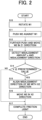
- Fig. 2 is an operation flowchart including misalignment correction
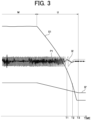
- Fig. 3 is a diagram for explaining rotation speed S1 and a rotation phase P1 of the first spindle 10 in friction joint (including a friction step M and the upsetting step U) and a current value I2 supplied to the X2-axis motor 25c.
- the length of the workpiece W1 becomes short each time a cut-off process is performed.
- the overall length of the workpiece W1 held by the first spindle 10 becomes short to be from the vicinity of the tip of the first spindle 10 to the guide bush 18. This shortened portion becomes a remaining workpiece that cannot be cut.
- the short workpiece held by the first spindle 10 is transferred to the second spindle 20 in order to effectively use the remaining workpiece.
- the axial center of the first spindle 10 and the axial center of the second spindle 20 are arranged concentrically, and for example, the second spindle 20 is brought closer to the first spindle 10.
- the chuck of the first spindle 10 is opened, and the new workpiece W1 is supplied from behind the first spindle 10.
- the newly supplied workpiece W1 is held by the first spindle 10.
- the short workpiece that has been held by the first spindle 10 (which will eventually become the remaining workpiece W2) is pushed out of the guide bush 18 to the front side of the support base 17.
- the remaining workpiece W2 is held by the second spindle 20.
- step S10 in Fig. 2 in a state where the first spindle 10 rotates but the second spindle 20 does not rotate (step S10 in Fig. 2 ), for example, the second spindle 20 is brought closer to the first spindle 10, and the rear end portion of the remaining workpiece W2 is pushed against the front end portion of the new workpiece W1 so as to apply a predetermined pressure (step S11: start of the friction step M).
- step S11 start of the friction step M
- the second spindle 20 may also be rotated. In that case, the first spindle 10 may be rotated in the same direction as or in the opposite direction to the rotation direction of the second spindle 20. Alternatively, only the second spindle 20 may be rotated. Also, in the present example, only the second spindle 20 is moved in the Z2-axis direction.
- first spindle 10 may be moved in the Z1-axis direction, or both the first spindle 10 and the second spindle 20 may be moved to bring the rear end portion of the remaining workpiece W2 into contact with the front end portion of the workpiece W1.
- Step S12 End of the friction step M, start of the upsetting step U.
- the control section 40a outputs a rotation stop command to the first spindle 10.
- the rotation speed S1 of the first spindle 10 is gradually reduced.
- timing of outputting the rotation stop command and timing of applying the stronger pressure to push the remaining workpiece W2 against the workpiece W1 are same as each other, but these timing may be different.
- the degree of softening by detecting decrease in the current value of the Z2-axis motor 24c (indicated by I2' in Fig. 3 ). Further, it is also possible to determine in advance the condition for softening the contact portion by a preliminary experiment and, on the basis of this condition, apply friction to the contact portion between the remaining workpiece W2 and the workpiece W1.
- step S11 in Fig. 2 After the remaining workpiece W2 is pushed against the rotating workpiece W1 (step S11 in Fig. 2 ), in a state where the workpiece W1 is held by the first spindle 10 and the remaining workpiece W2 is held by the second spindle 20, if only the first spindle 10 is rotationally driven, the rotation of the first spindle 10 is transmitted to the second spindle 20 via the workpiece W1 and the remaining workpiece W2, so that the second spindle 20 is also rotated together.
- the second spindle 20 vibrates in the X2-axis direction with amplitude twice the misalignment amount s (the distance between the axial center C1 of the workpiece W1 and the axial center C2 of the remaining workpiece W2) with respect to the axial center C1 of the first spindle 10, which is indicated by the solid line and the two-dot chain line in Fig. 4 .
- the position of the second spindle 20 in the X2-axis direction is determined by the X2-axis motor 25c, and the X2-axis motor 25c is controlled by the control section 40a to determine the position of the second spindle 20 in the X2-axis direction.
- the X2-axis motor 25c is in a rotationally driven state. Therefore, if vibration due to misalignment is applied to the X2-axis motor 25c, the current value I2 supplied from the control section 40a to the X2-axis motor 25c increases or decreases according to the rotation phase of the second spindle 20.
- the current value I2 supplied to the X2-axis motor 25c fluctuates with amplitude corresponding to twice the amplitude of the misalignment amount s during the upsetting step U, which is indicated by the solid line in the graph with X2-axis position (vertical axis) and time (horizontal axis) in Fig. 5 .
- the current value detecting means 40d detects the fluctuation range (difference between the maximum value and the minimum value) of the current value I2 supplied to the X2-axis motor 25c, for example, over a predetermined period. Then, the misalignment amount detecting means 40c obtains, for example, the average value of the fluctuation range of the current value I2, and, by hypothesizing that the half value of this average value corresponds to the misalignment amount s, detects the misalignment amount s of the remaining workpiece W2 with respect to the integrally jointed workpiece W1 (step S13 in Fig. 2 ).
- the misalignment amount detecting means 40c the degree of misalignment between the workpiece W1 and the remaining workpiece W2 can be determined during the friction joint of the workpiece W1 and the remaining workpiece W2.
- the desired operation for example, elimination of misalignment
- deburring operation can be started quickly. As a result, it is possible to reduce manufacturing costs of products and stabilize quality.
- the misalignment amount s of the remaining workpiece W2 with respect to the workpiece W1 can be obtained easily and accurately.
- the fluctuation (maximum value and minimum value) of the current value I2 supplied to the X2-axis motor 25c occurs substantially at the same rotation phase of the workpiece W1. Therefore, by comparing the fluctuation of the current value I2 with the rotation phase P1 of the first spindle 10, the misalignment direction of the remaining workpiece W2 with respect to the workpiece W1 can also be found.
- the rotation phase P1 of the first spindle 10 (indicated by the dashed line in the figure) and the current value I2 supplied to the X2-axis motor 25c (indicated by the solid line in the figure) are, for example, in a relationship in which the X2-axis motor 25c rotates approximately once while the spindle motor 13 rotates twice. If the remaining workpiece W2 is misaligned with respect to the workpiece W1 in the positive direction of the X2 axis, the current value I2 supplied to the X2 axis motor 25c increases in the positive direction.
- the rotation phase P1 of the first spindle 10 is, for example, 270°
- the current value I2 supplied to the X2-axis motor 25c reaches the maximum value. Therefore, it can be seen that the misalignment direction of the remaining workpiece W2 is the direction connecting the axial center C1 of the first spindle 10 and the position of the rotation phase of 270°.
- step S13 of Fig. 2 the upsetting step U of Fig. 3
- the misalignment direction detecting means 40e detects the misalignment direction of the remaining workpiece W2 with respect to the workpiece W1 by comparing the misalignment amount s of the remaining workpiece W2 with respect to the workpiece W1, which is detected by the misalignment amount detecting means 40c, and the rotation phase P1 of the first spindle 10 detected by the rotation angle detecting means 40f, In this way, the misalignment direction of the remaining workpiece W2 with respect to the workpiece W1 can be obtained by the misalignment direction detecting means 40e during the friction joint of the workpiece W1 and the remaining workpiece W2.
- the control section 40a determines whether or not the misalignment amount s detected by the misalignment amount detecting means 40c is equal to or larger than a predetermined value at which misalignment correction is required (step S14 in Fig. 2 ). If the misalignment amount s detected by the misalignment amount detecting means 40c is equal to or larger than the predetermined value (YES in step S14), the process proceeds to step S15 to correct the misalignment. On the other hand, if the misalignment amount s detected by the misalignment amount detecting means 40c is less than the predetermined value (NO in step S14), the process proceeds to step S17.
- step S14 the control section 40a outputs a drive signal to the spindle motor 13 to align the misalignment direction of the remaining workpiece W2 with respect to the workpiece W1 with the X2 direction (step S15). Specifically, as shown in Fig. 6A , if the misalignment direction of the remaining workpiece W2 with respect to the workpiece W1 (the direction connecting the axial center C1 of the workpiece W1 and the axial center C2 of the remaining workpiece W2) is not parallel to the X2 axis, the first spindle 10 is rotated to align the misalignment direction with the X2 axis direction.
- the control section 40a outputs a drive signal to the X2-axis motor 25c to move the second spindle 20 in the X2-axis direction in which the misalignment amount s decreases as indicated by the arrow in Fig. 6B (step S16 in Fig. 2 ).
- the second spindle 20 is moved in the direction, in which the distance from the axial center C2 of the remaining workpiece W2 to the axial center C1 of the workpiece W1 becomes short, by, for example, half the average value of the fluctuation range of the current value I2, so that the axial center of the remaining workpiece W2 and the axial center of the workpiece W1 correspond to each other ( Fig. 6C ).
- misalignment of the remaining workpiece W2 can be eliminated during the friction joint of the workpiece W1 and the remaining workpiece W2.
- control section 40a outputs a drive signal to the Z2-axis motor 24c to further push the rear end portion of the remaining workpiece W2 against the front end portion of the workpiece W1 to complete the friction joint (step S17 in Fig. 2 ).
- the timing of moving the second spindle 20 in the X2-axis direction (step S16) the temperature of the contact portion between the remaining workpiece W2 and the workpiece W1 is high, and it is only necessary that the remaining workpiece W2 is in a state of being able to be moved in a direction intersecting the axial center of the remaining workpiece W2. Therefore, in addition to the time T3 described above, for example, the timing may be immediately before the first spindle 10 stops rotating (indicated by time T2 in Fig. 3 ) or while the rotation speed S1 of the first spindle 10 is gradually decreasing (indicated by time T1).
- the tool 30 is used to cut off burrs generated at the joint portion between the remaining workpiece W2 and the workpiece W1.
- the tool 30 is arranged, for example, closer to the second spindle 20 than the joint portion between the remaining workpiece W2 and the workpiece W1, and is set to a predetermined cutting amount. Then, while rotating the first spindle 10, the tool 30 is moved closer to the first spindle 10 than the joint portion between the remaining workpiece W2 and the workpiece W1 to deburr.
- the front end portion of the workpiece W1 and the rear end portion of the remaining workpiece W2 are frictionally joined using the first spindle 10 and the second spindle 20 which are arranged so as to face each other.
- the manufacturing cost of products can be reduced by the automatic lathe 1 in which the joining process and the cutting process are combined (integrated).
- misalignment amount detecting means 40c calculates the misalignment amount s.
- the present invention can be applied to cases where, by taking a picture of the joining portion or the like with a camera or the like and performing image processing on the joining portion between the workpiece W1 and the remaining workpiece W2, or by measuring the joining portion using a laser as will be described later, misalignment amount of the remaining workpiece W2 with respect to the workpiece W1 is detected.
- the present invention is also applicable to cases where misalignment is not eliminated but the misalignment amount s is reduced.
- the guide bush 18 is provided between the first spindle 10 and the second spindle 20 .
- the guide bush 18 since it is only necessary to detect the misalignment amount s during the friction joint, the guide bush 18 can be omitted.
- the workpiece W1 may be made of material different from that of the remaining workpiece W2.
- the workpiece W1 and the remaining workpiece W2 may have different diameters.
- the present invention is not limited to the example of joint of the remaining workpiece W2 and can also be applied to cases where new workpieces are joined together.
- the present invention it is only necessary that at least the first spindle 10 is rotatable about the Z1 axis, the second spindle 20 is rotatable about the Z2 axis, either the first spindle 10 or the second spindle 20 is movable in the Z1 axis direction or in the Z2 axis direction, and either the first spindle 10 or the second spindle 20 is movable in the X1 axis direction or in the X2 axis direction, and thus, the present invention is not limited to the configuration of the present example.
- the movement is performed in the X2-axis direction perpendicular to the Z2-axis, but in the present invention, the moving direction can be changed as long as the moving direction intersects the Z2-axis.
- An automatic lathe (machine tool) 2 of the second example is an automatic lathe, in which the method of detecting the misalignment amount s of the remaining workpiece W2 with respect to the workpiece W1 is changed from that in the automatic lathe 1 of the first example.
- the automatic lathe 2 has a laser sensor 50, which is a type of optical sensors controlled by the control device 40, on the bed 1a.
- the laser sensor 50 irradiates the remaining workpiece W2 with laser light L in parallel with the X2 axis to detect distance D in the X2 axis direction between the laser sensor 50 and the peripheral surface of the remaining workpiece W2.
- the distance D between the laser sensor 50 and the peripheral surface of the remaining workpiece W2 fluctuates with amplitude twice the misalignment amount s during the upsetting step U with the distance O being the center of the fluctuation.
- the distance O is the distance in the X2 axis direction between the laser sensor 50 and the peripheral surface of the workpiece W1
- this fluctuation is indicated by the solid line in the graph with distance (vertical axis) and time (horizontal axis) in Fig. 9 .
- the misalignment amount detecting means 40c detects the maximum value of the fluctuation value in the X2-axis direction of the peripheral surface of the remaining workpiece W2 with respect to the axial center C1 of the workpiece W1, that is, the misalignment amount s of the remaining workpiece W2 with respect to the integrally joined workpiece W1, on the basis of an output value D of the laser sensor 50 (the distance in the X2-axis direction between the laser sensor 50 and the peripheral surface of the remaining workpiece W2).
- the fluctuation (maximum value and minimum value) of the output value D of the laser sensor 50 occurs substantially at the same rotation phase of the workpiece W1. Therefore, by comparing the fluctuation of the output value D with the rotation phase P1 of the first spindle 10, the misalignment direction of the remaining workpiece W2 with respect to the workpiece W1 can also be found.
- the rotation phase P1 of the first spindle 10 (indicated by the dashed line in the figure) and the output value D of the laser sensor 50 (indicated by the solid line in the figure) are, for example, in a relationship in which the remaining workpiece W2 rotates approximately once while the spindle motor 13 (that is, the workpiece W1) rotates twice. If the remaining workpiece W2 is misaligned with respect to the workpiece W1 in the positive direction of the X2 axis, the output value D of the laser sensor 50 increases in the positive direction. Further, when the rotation phase P1 of the first spindle 10 is, for example, 270°, the output value D of the laser sensor 50 reaches the maximum value. Therefore, it can be seen that the misalignment direction of the remaining workpiece W2 is the direction connecting the axial center C1 of the first spindle 10 and the position of the rotation phase of 270°.
- the misalignment direction detecting means 40e detects the misalignment direction of the remaining workpiece W2 with respect to the workpiece W1 by comparing the misalignment amount s of the remaining workpiece W2 with respect to the workpiece W1, which is detected by the misalignment amount detecting means 40c, and the rotation phase P1 of the first spindle 10 detected by the rotation angle detecting means 40f, In this way, also in the automatic lathe 2 of the second example, the misalignment direction of the remaining workpiece W2 with respect to the workpiece W1 can be obtained by the misalignment direction detecting means 40e during the friction joint of the workpiece W1 and the remaining workpiece W2.
- the automatic lathe 2 comprises the laser sensor 50 for measuring the distance to the remaining workpiece W2, and the misalignment amount detecting means 40c obtains the misalignment amount s of the remaining workpiece W2 with respect to the workpiece W1 on the basis of the output value D of the laser sensor 50, so that the misalignment amount s can be directly detected from the shape of the peripheral surface of the remaining workpiece W2. Therefore, the misalignment amount s can be detected more accurately than cases where the misalignment amount s is indirectly detected on the basis of the load applied to X2 axis motor as in the first example.
- the laser sensor 50 irradiates the remaining workpiece W2 with laser light in parallel with the X2 axis to detect the misalignment amount s and the misalignment direction of the remaining workpiece W2 with respect to the workpiece W1.
- the laser irradiation direction may be any direction as long as the misalignment amount s can be calculated by the misalignment amount detecting means 40c and is not limited to the direction parallel with the X2 axis.
- the present example is described with the laser sensor 50 using the laser light L as an example of optical sensors.
- the optical sensor is not limited to the laser sensor, and can be appropriately selected according to the measurement accuracy.
- the sensor may be an optical sensor using emitted light such as LED light.
Landscapes
- Engineering & Computer Science (AREA)
- Mechanical Engineering (AREA)
- Human Computer Interaction (AREA)
- Manufacturing & Machinery (AREA)
- Physics & Mathematics (AREA)
- General Physics & Mathematics (AREA)
- Automation & Control Theory (AREA)
- Turning (AREA)
- Pressure Welding/Diffusion-Bonding (AREA)
- Automatic Control Of Machine Tools (AREA)
Abstract
Description
- The present invention relates to a machine tool for joining two workpieces into one workpiece and relates to a control method for the machine tool.
- In machine tools, material may be left unmachined. Due to such remaining material, it is difficult to reduce material costs and to contribute to environmental conservation. Therefore, it is conceivable to frictionally join a predetermined workpiece and the remaining workpiece to make the most effective use of materials.
- When the workpiece and the remaining workpiece are frictionally joined, misalignment may occur between the workpiece and the remaining workpiece. Therefore, for example, in the
patent literatures -
- [Patent Literature 1]
JP 05-208281 A - [Patent Literature 2]
JP 07-195183 A - However, with the techniques described in the
patent literatures - The present invention has been made in view of such actual circumstances, and it is an object of the present invention to provide a machine tool and a control method for the machine tool, which can determine the degree of misalignment during friction joint.
- Firstly, the present invention is characterized by a machine tool comprising: a first spindle for rotatably holding a first workpiece; a second spindle arranged so as to face the first spindle and for rotatably holding a second workpiece; and a control section for, while rotating at least one of the first workpiece held by the first spindle or the second workpiece held by the second spindle, relatively moving the first spindle and the second spindle so as to get closer to each other and pushing a rear end portion of the second workpiece against a front end portion of the first workpiece to frictionally join the first and second workpieces, wherein the control section has misalignment amount detecting means for detecting a misalignment amount of the second workpiece with respect to the first workpiece during the friction joint.
- Secondly, the present invention is characterized in that the machine tool comprises second spindle moving means for moving the second spindle in a direction intersecting a rotation axis of the second spindle during the friction joint on the basis of the misalignment amount of the second workpiece with respect to the first workpiece, which is detected by the misalignment amount detecting means.
- Thirdly, the present invention is characterized in that timing at which the second spindle is moved in the direction intersecting the rotation axis of the second spindle is immediately after the first spindle stops rotating, immediately before the first spindle stops rotating, or while rotation speed of the first spindle is gradually decreasing.
- Fourthly, the present invention is characterized in that the control section has misalignment direction detecting means for detecting a misalignment direction of the second workpiece with respect to the first workpiece during the friction joint by comparing the misalignment amount of the second workpiece with respect to the first workpiece, which is detected by the misalignment amount detecting means, and a rotation phase of the first spindle.
- Fifthly, the present invention is characterized in that the second spindle moving means moves the second spindle in the direction intersecting the rotation axis of the second spindle so as to decrease the misalignment amount of the second workpiece with respect to the first workpiece on the basis of the misalignment amount of the second workpiece with respect to the first workpiece, which is detected by the misalignment amount detecting means, and the misalignment direction of the second workpiece with respect to the first workpiece, which is detected by the misalignment direction detecting means.
- Sixthly, the present invention is characterized in that the misalignment amount detecting means obtains the misalignment amount of the second workpiece with respect to the first workpiece on the basis of a load applied to a motor for moving the second spindle in the direction intersecting the rotation axis of the second spindle.
- Seventhly, the present invention is characterized in that the misalignment amount detecting means obtains the misalignment amount of the second workpiece with respect to the first workpiece on the basis of an output value of an optical sensor for measuring distance to the second workpiece.
- Eighthly, the present invention is characterized by a control method of a machine tool comprising: a first spindle for rotatably holding a first workpiece; a second spindle arranged so as to face the first spindle and for rotatably holding a second workpiece transferred from the first spindle; and a control section for controlling operation of the first spindle and the second spindle, the control method comprising the steps of: while rotating at least one of the first workpiece held by the first spindle or the second workpiece held by the second spindle, relatively moving the first spindle and the second spindle so as to get closer to each other and bringing a rear end portion of the second workpiece into contact with a front end portion of a newly supplied first workpiece to generate friction; detecting a misalignment amount of the second workpiece with respect to the first workpiece during friction joint by pushing the rear end portion of the second workpiece against the front end portion of the first workpiece; detecting a misalignment direction of the second workpiece with respect to the first workpiece during the friction joint; and moving the second spindle in a direction intersecting a rotation axis of the second spindle during the friction joint so as to decrease the misalignment amount of the second workpiece with respect to the first workpiece on the basis of the detected misalignment amount of the second workpiece with respect to the first workpiece and the detected misalignment direction of the second workpiece with respect to the first workpiece.
- The present invention can obtain the following effects.
- The degree of misalignment between the first workpiece and the second workpiece can be determined by the misalignment amount detecting means during the friction joint of the first workpiece and the second workpiece. Therefore, since the desired operation (for example, elimination of misalignment) can be performed before the friction joint is completed, it is not necessary to confirm the misalignment, correct the misaligned workpiece or the like after the friction joint. In addition, for example, deburring of the joint portion can be started quickly. As a result, it is possible to reduce manufacturing costs of products and stabilize quality.
-
-
Fig. 1 is a schematic configuration diagram of an automatic lathe as the first example of a machine tool according to the present invention. -
Fig. 2 is an operation flow chart including misalignment correction. -
Fig. 3 is a diagram illustrating a rotation phase of the first spindle and a current value supplied to an X2-axis motor in friction joint. -
Fig. 4 is a diagram illustrating deflection of a remaining workpiece due to misalignment. -
Fig. 5 is a diagram illustrating the rotation phase of the first spindle and the current value supplied to the X2-axis motor in an upsetting step. -
Fig. 6A is a diagram illustrating misalignment of the remaining workpiece with respect to a joined workpiece. -
Fig. 6B is a diagram illustrating operation of aligning a misalignment direction with the X2-axis direction. -
Fig. 6C is a diagram illustrating operation to eliminate misalignment. -
Fig. 7 is a schematic configuration diagram of an automatic lathe as the second example of a machine tool according to the present invention. -
Fig. 8 is a diagram illustrating deflection of a remaining workpiece due to misalignment in the second example. -
Fig. 9 is a diagram illustrating a rotation phase of the first spindle and fluctuation of distance between a laser sensor and a peripheral surface of the remaining workpiece in an upsetting step of the second example. - Hereinafter, a machine tool and a method for controlling the machine tool according to the first example of the present invention will be described with reference to drawings.
- As shown in
Fig. 1 , an automatic lathe (machine tool) 1 comprises afirst spindle 10 and atool post 31. Thefirst spindle 10 can grip (hold) a workpiece W1 via a chuck. This chuck is configured concentrically with thefirst spindle 10 and is rotatable integrally with thefirst spindle 10. - The workpiece W1 is a long round bar and is fed from the rear end of the
first spindle 10 using a pushing member of a bar feeder. A finger chuck is provided at the tip of the pushing member, and the finger chuck grips the rear end of the workpiece W1. - The
first spindle 10 is rotatably supported by aspindle headstock 12 with the Z1 axis direction shown inFig. 1 as the rotation axis, and is rotationally driven by the power of aspindle motor 13 provided on thespindle headstock 12. Thespindle headstock 12 is mounted on a Z1-axisdirection feeding mechanism 14 and is movable in the Z1-axis direction. - The Z1-axis
direction feeding mechanism 14 has a Z1-axis rail 14a, which is fixed to abed 1a and extends in the Z1-axis direction. A Z1-axis slider 14b, which slides along the Z1-axis direction by a Z1-axis motor 14c, is mounted on the Z1-axis rail 14a. Thespindle headstock 12 is provided on the Z1-axis slider 14b. - A
guide bush 18 is provided in front of thespindle headstock 12 to support the cutting position. Theguide bush 18 is supported by asupport base 17, and thesupport base 17 is fixed to thebed 1a. The workpiece W1 is rotatably supported by theguide bush 18 around the Z1 axis and fed to the front side of thesupport base 17. - In this way, if the
guide bush 18 is provided in front of thefirst spindle 10, the material from the vicinity of the tip of thefirst spindle 10 to theguide bush 18 becomes a remaining workpiece W2 that cannot be cut. By joining the remaining workpiece W2 and the newly supplied workpiece W1, the material can be effectively used, and the material costs can be reduced. - A moving table 32 is provided on the front side of the
support base 17. The moving table 32 moves thetool post 31 in the X1-axis direction orthogonal to the Z1-axis direction and in the Y1-axis direction orthogonal to the Z1-axis and X1-axis directions. - A
tool 30 is mounted on thetool post 31 with the tip of thetool 30 directed in the X1-axis direction. The workpiece W1 can be machined with thetool 30 by moving thefirst spindle 10 in the Z1-axis direction and moving thetool post 31 in the X1-axis direction or the Y1-axis direction. - The
automatic lathe 1 comprises asecond spindle 20 at a position facing thefirst spindle 10. Thesecond spindle 20 can grip (hold) the remaining workpiece W2 via a chuck. This chuck is configured concentrically with thesecond spindle 20 and is rotatable integrally with thesecond spindle 20. - The remaining workpiece W2 is, for example, a round bar having the same diameter as the workpiece W1, and is a remaining material in the
first spindle 10 that could not be machined. The remaining workpiece W2 is, for example, transferred from thefirst spindle 10 to thesecond spindle 20 and then held by thesecond spindle 20. - The
second spindle 20 is rotatably supported by aspindle headstock 22 with the Z2 axis direction parallel to the Z1-axis direction as the rotation axis, and is rotationally driven by the power of aspindle motor 23 provided on thespindle headstock 22. Thespindle headstock 22 is mounted on a Z2-axisdirection feeding mechanism 24 and an X2-axisdirection feeding mechanism 25 and is movable in the Z2-axis direction and the X2-axis direction. - The Z2-axis
direction feeding mechanism 24 has a Z2-axis rail 24a, which, for example, is arranged on the X2-axisdirection feeding mechanism 25 and extends in the Z2-axis direction. A Z2-axis slider 24b, which slides along the Z2-axis direction by a Z2-axis motor 24c, is mounted on the Z2-axis rail 24a. Thespindle headstock 22 is provided on the Z2-axis slider 24b. - The X2-axis
direction feeding mechanism 25 has an X2-axis rail 25a, which, for example, is fixed to thebed 1a and parallel to the X1-axis direction. An X2-axis slider 25b, which slides along the X2-axis direction by an X2-axis motor 25c, is mounted on the X2-axis rail 25a. The Z2-axis rail 24a of the Z2-axisdirection feeding mechanism 24 is provided on the X2-axis slider 25b. The X2-axisdirection feeding mechanism 25 corresponds to second spindle moving means in the present invention, and the X2-axis motor 25c corresponds to a motor in the present invention. - Rotation of the
first spindle 10 and thesecond spindle 20 and movement of thefirst spindle 10, thesecond spindle 20 and the moving table 32 are controlled by acontrol device 40. Thecontrol device 40 has acontrol section 40a and aninput section 40b, which are connected with each other via a bus. - The
control section 40a is composed of a CPU, a memory or the like, loads various programs and data stored in the ROM or the like into the RAM, and executes the program. Thereby, the operation of theautomatic lathe 1 can be controlled on the basis of the program. - The rotation of the
first spindle 10 and thesecond spindle 20, the movement of thefirst spindle 10, thesecond spindle 20 and the moving table 32 and the like can be set by a program or by inputting the rotation, the movement and the like to theinput section 40b. - Further, the
control section 40a functions as misalignmentamount detecting means 40c, currentvalue detecting means 40d, misalignment direction detecting means 40e and rotationangle detecting means 40f. - The current
value detecting means 40d detects the load applied to the X2-axis motor 25c as a current value. While the rear end portion of the remaining workpiece W2 is pushed against the front end portion of the workpiece W1 to be integrally joined (an upsetting step U inFig. 3 ), on the basis of the load detected by the currentvalue detecting means 40d, the misalignmentamount detecting means 40c obtains a misalignment amount s of the remaining workpiece W2 with respect to the integrally joined workpiece W1. - On the other hand, the rotation
angle detecting means 40f detects a rotation phase of thefirst spindle 10. While the rear end portion of the remaining workpiece W2 is pushed against the front end portion of the workpiece W1 to be integrally joined (the upsetting step U inFig. 3 ), by comparing the misalignment amount s obtained by the misalignmentamount detecting means 40c with the rotation phase of thefirst spindle 10 detected by the rotationangle detecting means 40f, the misalignmentdirection detecting means 40e obtains the misalignment direction of the remaining workpiece W2 with respect to the integrally joined workpiece W1. -
Fig. 2 is an operation flowchart including misalignment correction, andFig. 3 is a diagram for explaining rotation speed S1 and a rotation phase P1 of thefirst spindle 10 in friction joint (including a friction step M and the upsetting step U) and a current value I2 supplied to the X2-axis motor 25c. - In the
automatic lathe 1 as shown inFig. 1 , the length of the workpiece W1 becomes short each time a cut-off process is performed. As machining of the workpiece W1 progresses, the overall length of the workpiece W1 held by thefirst spindle 10 becomes short to be from the vicinity of the tip of thefirst spindle 10 to theguide bush 18. This shortened portion becomes a remaining workpiece that cannot be cut. In theautomatic lathe 1, the short workpiece held by thefirst spindle 10 is transferred to thesecond spindle 20 in order to effectively use the remaining workpiece. - Specifically, first, the axial center of the
first spindle 10 and the axial center of thesecond spindle 20 are arranged concentrically, and for example, thesecond spindle 20 is brought closer to thefirst spindle 10. Next, the chuck of thefirst spindle 10 is opened, and the new workpiece W1 is supplied from behind thefirst spindle 10. Then, the newly supplied workpiece W1 is held by thefirst spindle 10. When this new workpiece W1 is supplied to thefirst spindle 10, the short workpiece that has been held by the first spindle 10 (which will eventually become the remaining workpiece W2) is pushed out of theguide bush 18 to the front side of thesupport base 17. Then, the remaining workpiece W2 is held by thesecond spindle 20. - Next, for example, in a state where the
first spindle 10 rotates but thesecond spindle 20 does not rotate (step S10 inFig. 2 ), for example, thesecond spindle 20 is brought closer to thefirst spindle 10, and the rear end portion of the remaining workpiece W2 is pushed against the front end portion of the new workpiece W1 so as to apply a predetermined pressure (step S11: start of the friction step M). As a result, at the contact portion between the remaining workpiece W2 and the workpiece W1, frictional heat is generated due to the rotation speed difference between thefirst spindle 10 and thesecond spindle 20, and the contact portion is softened. - In the present example, only the
first spindle 10 is rotated, but since it is only necessary that thefirst spindle 10 and thesecond spindle 20 rotate with different speeds, thesecond spindle 20 may also be rotated. In that case, thefirst spindle 10 may be rotated in the same direction as or in the opposite direction to the rotation direction of thesecond spindle 20. Alternatively, only thesecond spindle 20 may be rotated. Also, in the present example, only thesecond spindle 20 is moved in the Z2-axis direction. However, only thefirst spindle 10 may be moved in the Z1-axis direction, or both thefirst spindle 10 and thesecond spindle 20 may be moved to bring the rear end portion of the remaining workpiece W2 into contact with the front end portion of the workpiece W1. - Subsequently, when the contact portion between the remaining workpiece W2 and the workpiece W1 is softened to the required degree, stronger pressure is applied to push the remaining workpiece W2 against the workpiece W1 so as to bring the
second spindle 20 even closer to the first spindle 10 (Step S12: End of the friction step M, start of the upsetting step U). At the same time, thecontrol section 40a outputs a rotation stop command to thefirst spindle 10. As a result, as shown inFig. 3 , the rotation speed S1 of thefirst spindle 10 is gradually reduced. - In the present embodiment, an example has been described in which timing of outputting the rotation stop command and timing of applying the stronger pressure to push the remaining workpiece W2 against the workpiece W1 are same as each other, but these timing may be different.
- Further, as a method of confirming the degree of softening, for example, it is possible to obtain the degree of softening by detecting decrease in the current value of the Z2-
axis motor 24c (indicated by I2' inFig. 3 ). Further, it is also possible to determine in advance the condition for softening the contact portion by a preliminary experiment and, on the basis of this condition, apply friction to the contact portion between the remaining workpiece W2 and the workpiece W1. - If the rotation of the
first spindle 10 stops while thesecond spindle 20 is being pushed against thefirst spindle 10, the rear end portion of the remaining workpiece W2 is pushed and joined with the front end portion of the workpiece W1 and the remaining workpiece W2 and the workpiece W1 are integrated. - Here, there is a case where the remaining workpiece W2 and the workpiece W1 are integrated with each other in a misalignment state. However, even if the remaining workpiece W2 is misaligned with respect to the workpiece W1, since the temperature of the contact portion between the remaining workpiece W2 and the workpiece W1 is high in the upsetting step U, it has been found that the remaining workpiece W2 can be moved in a direction intersecting the axial center of the remaining workpiece W2. Therefore, as described below, misalignment correction is performed during friction joint (before the joining phenomenon is completed).
- Specifically, after the remaining workpiece W2 is pushed against the rotating workpiece W1 (step S11 in
Fig. 2 ), in a state where the workpiece W1 is held by thefirst spindle 10 and the remaining workpiece W2 is held by thesecond spindle 20, if only thefirst spindle 10 is rotationally driven, the rotation of thefirst spindle 10 is transmitted to thesecond spindle 20 via the workpiece W1 and the remaining workpiece W2, so that thesecond spindle 20 is also rotated together. When misalignment occurs between the remaining workpiece W2 and the workpiece W1, thesecond spindle 20 vibrates in the X2-axis direction with amplitude twice the misalignment amount s (the distance between the axial center C1 of the workpiece W1 and the axial center C2 of the remaining workpiece W2) with respect to the axial center C1 of thefirst spindle 10, which is indicated by the solid line and the two-dot chain line inFig. 4 . - On the other hand, the position of the
second spindle 20 in the X2-axis direction is determined by the X2-axis motor 25c, and the X2-axis motor 25c is controlled by thecontrol section 40a to determine the position of thesecond spindle 20 in the X2-axis direction. (The X2-axis motor 25c is in a rotationally driven state.) Therefore, if vibration due to misalignment is applied to the X2-axis motor 25c, the current value I2 supplied from thecontrol section 40a to the X2-axis motor 25c increases or decreases according to the rotation phase of thesecond spindle 20. - Specifically, if vibration with amplitude twice the misalignment amount s is applied to the X2-
axis motor 25c, the current value I2 supplied to the X2-axis motor 25c fluctuates with amplitude corresponding to twice the amplitude of the misalignment amount s during the upsetting step U, which is indicated by the solid line in the graph with X2-axis position (vertical axis) and time (horizontal axis) inFig. 5 . - Then, the current
value detecting means 40d detects the fluctuation range (difference between the maximum value and the minimum value) of the current value I2 supplied to the X2-axis motor 25c, for example, over a predetermined period. Then, the misalignmentamount detecting means 40c obtains, for example, the average value of the fluctuation range of the current value I2, and, by hypothesizing that the half value of this average value corresponds to the misalignment amount s, detects the misalignment amount s of the remaining workpiece W2 with respect to the integrally jointed workpiece W1 (step S13 inFig. 2 ). - In this way, by the misalignment
amount detecting means 40c, the degree of misalignment between the workpiece W1 and the remaining workpiece W2 can be determined during the friction joint of the workpiece W1 and the remaining workpiece W2. Thus, as will be described later, since the desired operation (for example, elimination of misalignment) can be performed before the friction joint is completed, it is not necessary to confirm the misalignment, correct misaligned workpiece or the like after the friction joint. In addition, for example, deburring operation can be started quickly. As a result, it is possible to reduce manufacturing costs of products and stabilize quality. - Further, by using the load applied to the X2-
axis motor 25c, the misalignment amount s of the remaining workpiece W2 with respect to the workpiece W1 can be obtained easily and accurately. - In the present example, an example in which the load applied to the X2-
axis motor 25c is obtained from the average value of the fluctuation range of the current value I2 has been described, but the present invention is not limited to this example. For example, reference values for a fluctuation range of the current value I2 or for fluctuation of the current value I2 may be set only for predetermined timing, and an increase or decrease amount with respect to this reference value is used. Also, other parameters based on the current value I2 may be used. - On the other hand, the fluctuation (maximum value and minimum value) of the current value I2 supplied to the X2-
axis motor 25c occurs substantially at the same rotation phase of the workpiece W1. Therefore, by comparing the fluctuation of the current value I2 with the rotation phase P1 of thefirst spindle 10, the misalignment direction of the remaining workpiece W2 with respect to the workpiece W1 can also be found. - Specifically, as shown in
Fig. 5 , the rotation phase P1 of the first spindle 10 (indicated by the dashed line in the figure) and the current value I2 supplied to the X2-axis motor 25c (indicated by the solid line in the figure) are, for example, in a relationship in which the X2-axis motor 25c rotates approximately once while thespindle motor 13 rotates twice. If the remaining workpiece W2 is misaligned with respect to the workpiece W1 in the positive direction of the X2 axis, the current value I2 supplied to theX2 axis motor 25c increases in the positive direction. Further, when the rotation phase P1 of thefirst spindle 10 is, for example, 270°, the current value I2 supplied to the X2-axis motor 25c reaches the maximum value. Therefore, it can be seen that the misalignment direction of the remaining workpiece W2 is the direction connecting the axial center C1 of thefirst spindle 10 and the position of the rotation phase of 270°. - In step S13 of
Fig. 2 (the upsetting step U ofFig. 3 ), the misalignmentdirection detecting means 40e detects the misalignment direction of the remaining workpiece W2 with respect to the workpiece W1 by comparing the misalignment amount s of the remaining workpiece W2 with respect to the workpiece W1, which is detected by the misalignmentamount detecting means 40c, and the rotation phase P1 of thefirst spindle 10 detected by the rotationangle detecting means 40f, In this way, the misalignment direction of the remaining workpiece W2 with respect to the workpiece W1 can be obtained by the misalignment direction detecting means 40e during the friction joint of the workpiece W1 and the remaining workpiece W2. - Next, the
control section 40a determines whether or not the misalignment amount s detected by the misalignmentamount detecting means 40c is equal to or larger than a predetermined value at which misalignment correction is required (step S14 inFig. 2 ). If the misalignment amount s detected by the misalignmentamount detecting means 40c is equal to or larger than the predetermined value (YES in step S14), the process proceeds to step S15 to correct the misalignment. On the other hand, if the misalignment amount s detected by the misalignmentamount detecting means 40c is less than the predetermined value (NO in step S14), the process proceeds to step S17. - If the misalignment correction is required (YES in step S14), the
control section 40a outputs a drive signal to thespindle motor 13 to align the misalignment direction of the remaining workpiece W2 with respect to the workpiece W1 with the X2 direction (step S15). Specifically, as shown inFig. 6A , if the misalignment direction of the remaining workpiece W2 with respect to the workpiece W1 (the direction connecting the axial center C1 of the workpiece W1 and the axial center C2 of the remaining workpiece W2) is not parallel to the X2 axis, thefirst spindle 10 is rotated to align the misalignment direction with the X2 axis direction. - Next, for example, immediately after the
first spindle 10 stops rotating (indicated by time T3 inFig. 3 ), thecontrol section 40a outputs a drive signal to the X2-axis motor 25c to move thesecond spindle 20 in the X2-axis direction in which the misalignment amount s decreases as indicated by the arrow inFig. 6B (step S16 inFig. 2 ). More specifically, thesecond spindle 20 is moved in the direction, in which the distance from the axial center C2 of the remaining workpiece W2 to the axial center C1 of the workpiece W1 becomes short, by, for example, half the average value of the fluctuation range of the current value I2, so that the axial center of the remaining workpiece W2 and the axial center of the workpiece W1 correspond to each other (Fig. 6C ). As a result, misalignment of the remaining workpiece W2 can be eliminated during the friction joint of the workpiece W1 and the remaining workpiece W2. - Subsequently, the
control section 40a outputs a drive signal to the Z2-axis motor 24c to further push the rear end portion of the remaining workpiece W2 against the front end portion of the workpiece W1 to complete the friction joint (step S17 inFig. 2 ). - At the timing of moving the
second spindle 20 in the X2-axis direction (step S16), the temperature of the contact portion between the remaining workpiece W2 and the workpiece W1 is high, and it is only necessary that the remaining workpiece W2 is in a state of being able to be moved in a direction intersecting the axial center of the remaining workpiece W2. Therefore, in addition to the time T3 described above, for example, the timing may be immediately before thefirst spindle 10 stops rotating (indicated by time T2 inFig. 3 ) or while the rotation speed S1 of thefirst spindle 10 is gradually decreasing (indicated by time T1). - After that, the
tool 30 is used to cut off burrs generated at the joint portion between the remaining workpiece W2 and the workpiece W1. In this cutting-off process, while the workpiece W1is held by thefirst spindle 10, holding of the remaining workpiece W2 by thesecond spindle 20 is released. Thetool 30 is arranged, for example, closer to thesecond spindle 20 than the joint portion between the remaining workpiece W2 and the workpiece W1, and is set to a predetermined cutting amount. Then, while rotating thefirst spindle 10, thetool 30 is moved closer to thefirst spindle 10 than the joint portion between the remaining workpiece W2 and the workpiece W1 to deburr. - In this way, the front end portion of the workpiece W1 and the rear end portion of the remaining workpiece W2 are frictionally joined using the
first spindle 10 and thesecond spindle 20 which are arranged so as to face each other. The manufacturing cost of products can be reduced by theautomatic lathe 1 in which the joining process and the cutting process are combined (integrated). - In the above example, an example in which the misalignment
amount detecting means 40c calculates the misalignment amount s has been described. However, the present invention can be applied to cases where, by taking a picture of the joining portion or the like with a camera or the like and performing image processing on the joining portion between the workpiece W1 and the remaining workpiece W2, or by measuring the joining portion using a laser as will be described later, misalignment amount of the remaining workpiece W2 with respect to the workpiece W1 is detected. - Further, in the above example, an example in which the misalignment amount s is eliminated has been described. However, the present invention is also applicable to cases where misalignment is not eliminated but the misalignment amount s is reduced.
- Further, in the above example, an example in which the
guide bush 18 is provided between thefirst spindle 10 and thesecond spindle 20 has been described. However, in the present invention, since it is only necessary to detect the misalignment amount s during the friction joint, theguide bush 18 can be omitted. Further, the workpiece W1 may be made of material different from that of the remaining workpiece W2. Further, the workpiece W1 and the remaining workpiece W2 may have different diameters. Furthermore, in the above example, an example in which the remaining workpiece W2 and the workpiece W1 are frictionally joined has been described, but the present invention is not limited to the example of joint of the remaining workpiece W2 and can also be applied to cases where new workpieces are joined together. - Further, in the present invention, it is only necessary that at least the
first spindle 10 is rotatable about the Z1 axis, thesecond spindle 20 is rotatable about the Z2 axis, either thefirst spindle 10 or thesecond spindle 20 is movable in the Z1 axis direction or in the Z2 axis direction, and either thefirst spindle 10 or thesecond spindle 20 is movable in the X1 axis direction or in the X2 axis direction, and thus, the present invention is not limited to the configuration of the present example. - Further, in the above example, the movement is performed in the X2-axis direction perpendicular to the Z2-axis, but in the present invention, the moving direction can be changed as long as the moving direction intersects the Z2-axis.
- Next, a machine tool and a control method of the machine tool according to the second example of the present invention will be described with reference to drawings.
- An automatic lathe (machine tool) 2 of the second example is an automatic lathe, in which the method of detecting the misalignment amount s of the remaining workpiece W2 with respect to the workpiece W1 is changed from that in the
automatic lathe 1 of the first example. - Since many components of the
automatic lathe 2 in the second example are common to those of theautomatic lathe 1 in the first example, detailed description of the common components will be omitted. - As shown in
Fig. 7 , theautomatic lathe 2 has alaser sensor 50, which is a type of optical sensors controlled by thecontrol device 40, on thebed 1a. As shown inFig. 8 , thelaser sensor 50 irradiates the remaining workpiece W2 with laser light L in parallel with the X2 axis to detect distance D in the X2 axis direction between thelaser sensor 50 and the peripheral surface of the remaining workpiece W2. - Next, detection of the misalignment amount s of the remaining workpiece W2 with respect to the workpiece W1 by the
automatic lathe 2 in the second example will be described. - For example, if vibration with amplitude twice the misalignment amount s is applied to the remaining workpiece W2, the distance D between the
laser sensor 50 and the peripheral surface of the remaining workpiece W2 fluctuates with amplitude twice the misalignment amount s during the upsetting step U with the distance O being the center of the fluctuation. Here, the distance O is the distance in the X2 axis direction between thelaser sensor 50 and the peripheral surface of the workpiece W1, and this fluctuation is indicated by the solid line in the graph with distance (vertical axis) and time (horizontal axis) inFig. 9 . - Then, in the upsetting step U, the misalignment
amount detecting means 40c detects the maximum value of the fluctuation value in the X2-axis direction of the peripheral surface of the remaining workpiece W2 with respect to the axial center C1 of the workpiece W1, that is, the misalignment amount s of the remaining workpiece W2 with respect to the integrally joined workpiece W1, on the basis of an output value D of the laser sensor 50 (the distance in the X2-axis direction between thelaser sensor 50 and the peripheral surface of the remaining workpiece W2). - Next, detection of the misalignment direction of the remaining workpiece W2 with respect to the workpiece W1 in the
automatic lathe 2 of the second example will be described. - Also in the second example, the fluctuation (maximum value and minimum value) of the output value D of the
laser sensor 50 occurs substantially at the same rotation phase of the workpiece W1. Therefore, by comparing the fluctuation of the output value D with the rotation phase P1 of thefirst spindle 10, the misalignment direction of the remaining workpiece W2 with respect to the workpiece W1 can also be found. - Specifically, as shown in
Fig. 9 , the rotation phase P1 of the first spindle 10 (indicated by the dashed line in the figure) and the output value D of the laser sensor 50 (indicated by the solid line in the figure) are, for example, in a relationship in which the remaining workpiece W2 rotates approximately once while the spindle motor 13 (that is, the workpiece W1) rotates twice. If the remaining workpiece W2 is misaligned with respect to the workpiece W1 in the positive direction of the X2 axis, the output value D of thelaser sensor 50 increases in the positive direction. Further, when the rotation phase P1 of thefirst spindle 10 is, for example, 270°, the output value D of thelaser sensor 50 reaches the maximum value. Therefore, it can be seen that the misalignment direction of the remaining workpiece W2 is the direction connecting the axial center C1 of thefirst spindle 10 and the position of the rotation phase of 270°. - Then, in the upsetting step U, as in the first example, the misalignment
direction detecting means 40e detects the misalignment direction of the remaining workpiece W2 with respect to the workpiece W1 by comparing the misalignment amount s of the remaining workpiece W2 with respect to the workpiece W1, which is detected by the misalignmentamount detecting means 40c, and the rotation phase P1 of thefirst spindle 10 detected by the rotationangle detecting means 40f, In this way, also in theautomatic lathe 2 of the second example, the misalignment direction of the remaining workpiece W2 with respect to the workpiece W1 can be obtained by the misalignment direction detecting means 40e during the friction joint of the workpiece W1 and the remaining workpiece W2. - As described above, in the second example, the
automatic lathe 2 comprises thelaser sensor 50 for measuring the distance to the remaining workpiece W2, and the misalignmentamount detecting means 40c obtains the misalignment amount s of the remaining workpiece W2 with respect to the workpiece W1 on the basis of the output value D of thelaser sensor 50, so that the misalignment amount s can be directly detected from the shape of the peripheral surface of the remaining workpiece W2. Therefore, the misalignment amount s can be detected more accurately than cases where the misalignment amount s is indirectly detected on the basis of the load applied to X2 axis motor as in the first example. - In the present example, as shown in
Fig. 8 , thelaser sensor 50 irradiates the remaining workpiece W2 with laser light in parallel with the X2 axis to detect the misalignment amount s and the misalignment direction of the remaining workpiece W2 with respect to the workpiece W1. However, the laser irradiation direction may be any direction as long as the misalignment amount s can be calculated by the misalignmentamount detecting means 40c and is not limited to the direction parallel with the X2 axis. - Further, the present example is described with the
laser sensor 50 using the laser light L as an example of optical sensors. However, the optical sensor is not limited to the laser sensor, and can be appropriately selected according to the measurement accuracy. For example, the sensor may be an optical sensor using emitted light such as LED light. -
- 1
- automatic lathe (machine tool)
- 1a
- bed
- 10
- first spindle
- 12
- spindle headstock
- 13
- spindle motor
- 14
- Z1-axis direction feeding mechanism
- 14a
- Z1-axis rail
- 14b
- Z1-axis slider
- 14c
- Z1-axis motor
- 17
- support base
- 18
- guide bush
- 20
- second spindle
- 22
- spindle headstock
- 23
- spindle motor
- 24
- Z2-axis direction feeding mechanism
- 24a
- Z2-axis rail
- 24b
- Z2-axis slider
- 24c
- Z2-axis motor
- 25
- X2-axis direction feeding mechanism (second spindle moving means)
- 25a
- X2-axis rail
- 25b
- X2-axis slider
- 25c
- X2-axis motor
- 30
- tool
- 31
- tool post
- 32
- moving table
- 40
- control device
- 40a
- control section
- 40b
- input section
- 40c
- misalignment amount detecting means
- 40d
- current value detecting means
- 40e
- misalignment direction detecting means
- 40f
- rotation angle detecting means
- 50
- laser sensor (optical sensor)
- W1
- workpiece (first workpiece)
- W2
- remaining workpiece (second workpiece)
- M
- friction step
- U
- upsetting step
- S1
- rotation speed
- P1
- rotation phase
- I2
- current value
- T1
- time
- T2
- time
- T3
- time
- s
- misalignment amount
- D
- distance in X2 axis direction between laser sensor and peripheral surface of remaining workpiece
- L
- laser light
Claims (8)
- A machine tool comprising:a first spindle for rotatably holding a first workpiece;a second spindle arranged so as to face the first spindle and for rotatably holding a second workpiece; anda control section for, while rotating at least one of the first workpiece held by the first spindle or the second workpiece held by the second spindle, relatively moving the first spindle and the second spindle so as to get closer to each other and pushing a rear end portion of the second workpiece against a front end portion of the first workpiece to frictionally join the first and second workpieces, whereinthe control section has misalignment amount detecting means for detecting a misalignment amount of the second workpiece with respect to the first workpiece during the friction joint.
- The machine tool according to claim 1 comprising second spindle moving means for moving the second spindle in a direction intersecting a rotation axis of the second spindle during the friction joint on the basis of the misalignment amount of the second workpiece with respect to the first workpiece, which is detected by the misalignment amount detecting means.
- The machine tool according to claim 2, wherein timing at which the second spindle is moved in the direction intersecting the rotation axis of the second spindle is immediately after the first spindle stops rotating, immediately before the first spindle stops rotating, or while rotation speed of the first spindle is gradually decreasing.
- The machine tool according to any one of claims 1 to 3, wherein the control section has misalignment direction detecting means for detecting a misalignment direction of the second workpiece with respect to the first workpiece during the friction joint by comparing the misalignment amount of the second workpiece with respect to the first workpiece, which is detected by the misalignment amount detecting means, and a rotation phase of the first spindle.
- The machine tool according to claim 4, wherein the second spindle moving means moves the second spindle in the direction intersecting the rotation axis of the second spindle so as to decrease the misalignment amount of the second workpiece with respect to the first workpiece on the basis of the misalignment amount of the second workpiece with respect to the first workpiece, which is detected by the misalignment amount detecting means, and the misalignment direction of the second workpiece with respect to the first workpiece, which is detected by the misalignment direction detecting means.
- The machine tool according to any one of claims 1 to 5, wherein the misalignment amount detecting means obtains the misalignment amount of the second workpiece with respect to the first workpiece on the basis of a load applied to a motor for moving the second spindle in the direction intersecting the rotation axis of the second spindle.
- The machine tool according to any one of claims 1 to 5, wherein the misalignment amount detecting means obtains the misalignment amount of the second workpiece with respect to the first workpiece on the basis of an output value of an optical sensor for measuring distance to the second workpiece.
- A control method of a machine tool comprising: a first spindle for rotatably holding a first workpiece; a second spindle arranged so as to face the first spindle and for rotatably holding a second workpiece transferred from the first spindle; and a control section for controlling operation of the first spindle and the second spindle, the control method comprising the steps of:while rotating at least one of the first workpiece held by the first spindle or the second workpiece held by the second spindle, relatively moving the first spindle and the second spindle so as to get closer to each other and bringing a rear end portion of the second workpiece into contact with a front end portion of a newly supplied first workpiece to generate friction;detecting a misalignment amount of the second workpiece with respect to the first workpiece during friction joint by pushing the rear end portion of the second workpiece against the front end portion of the first workpiece;detecting a misalignment direction of the second workpiece with respect to the first workpiece during the friction joint; andmoving the second spindle in a direction intersecting a rotation axis of the second spindle during the friction joint so as to decrease the misalignment amount of the second workpiece with respect to the first workpiece on the basis of the detected misalignment amount of the second workpiece with respect to the first workpiece and the detected misalignment direction of the second workpiece with respect to the first workpiece.
Applications Claiming Priority (2)
| Application Number | Priority Date | Filing Date | Title |
|---|---|---|---|
| JP2020112424 | 2020-06-30 | ||
| PCT/JP2021/024277 WO2022004625A1 (en) | 2020-06-30 | 2021-06-28 | Machine tool and method for controlling machine tool |
Publications (2)
| Publication Number | Publication Date |
|---|---|
| EP4129538A1 true EP4129538A1 (en) | 2023-02-08 |
| EP4129538A4 EP4129538A4 (en) | 2024-04-17 |
Family
ID=79315356
Family Applications (1)
| Application Number | Title | Priority Date | Filing Date |
|---|---|---|---|
| EP21833512.3A Pending EP4129538A4 (en) | 2020-06-30 | 2021-06-28 | MACHINE TOOL AND METHOD FOR CONTROLLING A MACHINE TOOL |
Country Status (7)
| Country | Link |
|---|---|
| US (1) | US12269111B2 (en) |
| EP (1) | EP4129538A4 (en) |
| JP (1) | JP7604489B2 (en) |
| KR (1) | KR20230028251A (en) |
| CN (1) | CN115702398B (en) |
| TW (1) | TWI887440B (en) |
| WO (1) | WO2022004625A1 (en) |
Families Citing this family (4)
| Publication number | Priority date | Publication date | Assignee | Title |
|---|---|---|---|---|
| JP7261678B2 (en) * | 2019-07-04 | 2023-04-20 | シチズン時計株式会社 | Machine tools and processing methods |
| JP7741367B2 (en) * | 2021-07-14 | 2025-09-18 | スター精密株式会社 | Machine Tool Systems |
| EP4549059A4 (en) * | 2022-06-30 | 2026-04-22 | Citizen Watch Co Ltd | Machine tool, and machine tool alignment method |
| CN117161674B (en) * | 2023-11-02 | 2024-02-09 | 兴化市广福金属制品有限公司 | Metal product butt welding device |
Family Cites Families (30)
| Publication number | Priority date | Publication date | Assignee | Title |
|---|---|---|---|---|
| US3541669A (en) * | 1968-11-20 | 1970-11-24 | Caterpillar Tractor Co | Orienting inertia welded parts |
| GB1264863A (en) | 1969-03-18 | 1972-02-23 | ||
| JPS4928338B1 (en) * | 1969-05-12 | 1974-07-25 | ||
| JPS5146634B2 (en) | 1971-08-18 | 1976-12-10 | ||
| DE3413023A1 (en) * | 1983-04-07 | 1984-10-11 | Rolls-Royce Ltd., London | METHOD FOR REGULATING A VEGETIVE OR FRICTION WELDING PROCESS |
| JP2551512B2 (en) | 1992-01-07 | 1996-11-06 | 新日本製鐵株式会社 | Welding material for high Cr ferritic heat resistant steel |
| JP2501702B2 (en) * | 1992-01-08 | 1996-05-29 | 千代田化工建設株式会社 | Friction welding machine |
| JPH05208281A (en) | 1992-01-31 | 1993-08-20 | Nippon Steel Corp | Detection of abnormality at the time of friction-press-joining steel pipe |
| JP3195872B2 (en) | 1994-01-05 | 2001-08-06 | 株式会社日立製作所 | Method and apparatus for judging quality of friction welding products |
| JPH09285876A (en) * | 1996-04-23 | 1997-11-04 | Daido Steel Co Ltd | Positioning method of materials to be welded in diffusion welding |
| JP3433621B2 (en) * | 1996-10-18 | 2003-08-04 | トヨタ自動車株式会社 | Friction welding method |
| US5858142A (en) * | 1997-02-27 | 1999-01-12 | Inertia Friction Welding, Inc. | Angular orientation control system for friction welding |
| JP3984723B2 (en) * | 1998-09-07 | 2007-10-03 | 株式会社豊田自動織機 | Clamp device and friction welding device |
| BE1012692A3 (en) * | 1999-06-01 | 2001-02-06 | Denys Nv | METHOD AND APPARATUS FOR WELDING elongate elements. |
| DE10330188A1 (en) * | 2003-07-03 | 2005-02-03 | Kuka Schweissanlagen Gmbh | Method and apparatus for pressure welding |
| DE102004001274A1 (en) * | 2004-01-08 | 2005-08-04 | Mtu Aero Engines Gmbh | rotary friction |
| GB0418524D0 (en) * | 2004-08-19 | 2004-09-22 | Rolls Royce Plc | Process and apparatus for inertia friction welding |
| US20070051776A1 (en) * | 2005-07-06 | 2007-03-08 | Ssd Control Technology, Inc. | Dual friction welder |
| JP5243083B2 (en) * | 2008-04-01 | 2013-07-24 | 株式会社豊田自動織機 | Friction welding method |
| EP2561948A1 (en) * | 2011-08-24 | 2013-02-27 | Wartmann Technologie AG | Device for and method of manufacturing a flange-tube-flange element using friction stir welding |
| JP5815462B2 (en) * | 2012-04-26 | 2015-11-17 | Dmg森精機株式会社 | Centering correction mechanism for workpieces on a lathe. |
| DE202012103219U1 (en) * | 2012-08-24 | 2013-12-02 | Kuka Systems Gmbh | Pressure welding apparatus |
| JP6155155B2 (en) * | 2013-09-27 | 2017-06-28 | 三菱重工業株式会社 | Friction stir tool, friction stir welding apparatus, and friction stir welding method |
| ES2807617T3 (en) * | 2014-03-26 | 2021-02-23 | Citizen Watch Co Ltd | Control device for machine tools and machine tools provided with said control device |
| GB201413923D0 (en) * | 2014-08-06 | 2014-09-17 | Rolls Royce Plc | Rotary friction welding |
| GB201501884D0 (en) * | 2015-02-05 | 2015-03-25 | Rolls Royce Plc | Friction welding |
| DE102015102353A1 (en) * | 2015-02-19 | 2016-08-25 | Kuka Industries Gmbh | Method and apparatus for friction welding |
| CN110475637B (en) * | 2017-03-29 | 2021-05-04 | 西铁城时计株式会社 | Machine tool control device and machine tool |
| WO2019102808A1 (en) * | 2017-11-27 | 2019-05-31 | シチズン時計株式会社 | Friction welding method and machine tool |
| JP7195160B2 (en) * | 2019-01-18 | 2022-12-23 | シチズン時計株式会社 | Machine Tools |
-
2021
- 2021-06-28 CN CN202180043055.9A patent/CN115702398B/en active Active
- 2021-06-28 KR KR1020227041591A patent/KR20230028251A/en active Pending
- 2021-06-28 US US17/923,643 patent/US12269111B2/en active Active
- 2021-06-28 JP JP2022533972A patent/JP7604489B2/en active Active
- 2021-06-28 TW TW110123935A patent/TWI887440B/en active
- 2021-06-28 EP EP21833512.3A patent/EP4129538A4/en active Pending
- 2021-06-28 WO PCT/JP2021/024277 patent/WO2022004625A1/en not_active Ceased
Also Published As
| Publication number | Publication date |
|---|---|
| KR20230028251A (en) | 2023-02-28 |
| WO2022004625A1 (en) | 2022-01-06 |
| US20230182230A1 (en) | 2023-06-15 |
| CN115702398B (en) | 2025-07-01 |
| US12269111B2 (en) | 2025-04-08 |
| TWI887440B (en) | 2025-06-21 |
| EP4129538A4 (en) | 2024-04-17 |
| TW202204074A (en) | 2022-02-01 |
| CN115702398A (en) | 2023-02-14 |
| JPWO2022004625A1 (en) | 2022-01-06 |
| JP7604489B2 (en) | 2024-12-23 |
Similar Documents
| Publication | Publication Date | Title |
|---|---|---|
| US12269111B2 (en) | Machine tool and control method of machine tool | |
| US11465230B2 (en) | Machine tool | |
| CN101663114B (en) | Numerically controlled lathe with guide bush and method of processing workpiece by using the numerically controlled lathe | |
| EP3718674B1 (en) | Friction welding method and machine tool | |
| US20100188035A1 (en) | Machine tool and controlling method thereof | |
| EP3912756B1 (en) | Machine tool | |
| JP6881725B2 (en) | Work processing method, spindle angle correction device and compound lathe | |
| US12162078B2 (en) | Machine tool | |
| JP7312762B2 (en) | Machine Tools | |
| JP6576758B2 (en) | Cutting apparatus and control method thereof | |
| US20220314332A1 (en) | Machine tool and control device for machine tool | |
| JP3331224B2 (en) | Lathe work confirmation method and gripping method | |
| US20170014963A1 (en) | Lathe | |
| WO2021193344A1 (en) | Machine tool and method for controlling machine tool | |
| JP2585768B2 (en) | Cutting feed setting device for machine tools | |
| JP3361119B2 (en) | Small diameter drilling method in lathe | |
| JP2005040930A (en) | Method for judging wear status of machining tools | |
| JP2024150161A (en) | Friction joining device and friction joining method |
Legal Events
| Date | Code | Title | Description |
|---|---|---|---|
| STAA | Information on the status of an ep patent application or granted ep patent |
Free format text: STATUS: THE INTERNATIONAL PUBLICATION HAS BEEN MADE |
|
| PUAI | Public reference made under article 153(3) epc to a published international application that has entered the european phase |
Free format text: ORIGINAL CODE: 0009012 |
|
| STAA | Information on the status of an ep patent application or granted ep patent |
Free format text: STATUS: REQUEST FOR EXAMINATION WAS MADE |
|
| 17P | Request for examination filed |
Effective date: 20221025 |
|
| AK | Designated contracting states |
Kind code of ref document: A1 Designated state(s): AL AT BE BG CH CY CZ DE DK EE ES FI FR GB GR HR HU IE IS IT LI LT LU LV MC MK MT NL NO PL PT RO RS SE SI SK SM TR |
|
| DAV | Request for validation of the european patent (deleted) | ||
| DAX | Request for extension of the european patent (deleted) | ||
| A4 | Supplementary search report drawn up and despatched |
Effective date: 20240320 |
|
| RIC1 | Information provided on ipc code assigned before grant |
Ipc: G05B 19/401 20060101ALI20240314BHEP Ipc: B23Q 17/22 20060101ALI20240314BHEP Ipc: G05B 19/404 20060101ALI20240314BHEP Ipc: G05B 19/18 20060101ALI20240314BHEP Ipc: B23K 20/12 20060101ALI20240314BHEP Ipc: B23B 19/02 20060101AFI20240314BHEP |
|
| STAA | Information on the status of an ep patent application or granted ep patent |
Free format text: STATUS: EXAMINATION IS IN PROGRESS |
|
| 17Q | First examination report despatched |
Effective date: 20250916 |