EP4129500A1 - Down separation system, down separation method, and method for producing recycled down - Google Patents
Down separation system, down separation method, and method for producing recycled down Download PDFInfo
- Publication number
- EP4129500A1 EP4129500A1 EP21780657.9A EP21780657A EP4129500A1 EP 4129500 A1 EP4129500 A1 EP 4129500A1 EP 21780657 A EP21780657 A EP 21780657A EP 4129500 A1 EP4129500 A1 EP 4129500A1
- Authority
- EP
- European Patent Office
- Prior art keywords
- feather
- covering
- feathers
- separation
- product
- Prior art date
- Legal status (The legal status is an assumption and is not a legal conclusion. Google has not performed a legal analysis and makes no representation as to the accuracy of the status listed.)
- Granted
Links
Images


Classifications
-
- B—PERFORMING OPERATIONS; TRANSPORTING
- B07—SEPARATING SOLIDS FROM SOLIDS; SORTING
- B07B—SEPARATING SOLIDS FROM SOLIDS BY SIEVING, SCREENING, SIFTING OR BY USING GAS CURRENTS; SEPARATING BY OTHER DRY METHODS APPLICABLE TO BULK MATERIAL, e.g. LOOSE ARTICLES FIT TO BE HANDLED LIKE BULK MATERIAL
- B07B11/00—Arrangement of accessories in apparatus for separating solids from solids using gas currents
- B07B11/02—Arrangement of air or material conditioning accessories
-
- B—PERFORMING OPERATIONS; TRANSPORTING
- B68—SADDLERY; UPHOLSTERY
- B68G—METHODS, EQUIPMENT, OR MACHINES FOR USE IN UPHOLSTERING; UPHOLSTERY NOT OTHERWISE PROVIDED FOR
- B68G3/00—Treating materials to adapt them specially as upholstery filling
-
- B—PERFORMING OPERATIONS; TRANSPORTING
- B07—SEPARATING SOLIDS FROM SOLIDS; SORTING
- B07B—SEPARATING SOLIDS FROM SOLIDS BY SIEVING, SCREENING, SIFTING OR BY USING GAS CURRENTS; SEPARATING BY OTHER DRY METHODS APPLICABLE TO BULK MATERIAL, e.g. LOOSE ARTICLES FIT TO BE HANDLED LIKE BULK MATERIAL
- B07B11/00—Arrangement of accessories in apparatus for separating solids from solids using gas currents
- B07B11/06—Feeding or discharging arrangements
-
- B—PERFORMING OPERATIONS; TRANSPORTING
- B07—SEPARATING SOLIDS FROM SOLIDS; SORTING
- B07B—SEPARATING SOLIDS FROM SOLIDS BY SIEVING, SCREENING, SIFTING OR BY USING GAS CURRENTS; SEPARATING BY OTHER DRY METHODS APPLICABLE TO BULK MATERIAL, e.g. LOOSE ARTICLES FIT TO BE HANDLED LIKE BULK MATERIAL
- B07B4/00—Separating solids from solids by subjecting their mixture to gas currents
- B07B4/02—Separating solids from solids by subjecting their mixture to gas currents while the mixtures fall
-
- B—PERFORMING OPERATIONS; TRANSPORTING
- B07—SEPARATING SOLIDS FROM SOLIDS; SORTING
- B07B—SEPARATING SOLIDS FROM SOLIDS BY SIEVING, SCREENING, SIFTING OR BY USING GAS CURRENTS; SEPARATING BY OTHER DRY METHODS APPLICABLE TO BULK MATERIAL, e.g. LOOSE ARTICLES FIT TO BE HANDLED LIKE BULK MATERIAL
- B07B7/00—Selective separation of solid materials carried by, or dispersed in, gas currents
- B07B7/01—Selective separation of solid materials carried by, or dispersed in, gas currents using gravity
-
- B—PERFORMING OPERATIONS; TRANSPORTING
- B07—SEPARATING SOLIDS FROM SOLIDS; SORTING
- B07B—SEPARATING SOLIDS FROM SOLIDS BY SIEVING, SCREENING, SIFTING OR BY USING GAS CURRENTS; SEPARATING BY OTHER DRY METHODS APPLICABLE TO BULK MATERIAL, e.g. LOOSE ARTICLES FIT TO BE HANDLED LIKE BULK MATERIAL
- B07B4/00—Separating solids from solids by subjecting their mixture to gas currents
- B07B4/02—Separating solids from solids by subjecting their mixture to gas currents while the mixtures fall
- B07B4/06—Separating solids from solids by subjecting their mixture to gas currents while the mixtures fall using revolving drums
-
- B—PERFORMING OPERATIONS; TRANSPORTING
- B07—SEPARATING SOLIDS FROM SOLIDS; SORTING
- B07B—SEPARATING SOLIDS FROM SOLIDS BY SIEVING, SCREENING, SIFTING OR BY USING GAS CURRENTS; SEPARATING BY OTHER DRY METHODS APPLICABLE TO BULK MATERIAL, e.g. LOOSE ARTICLES FIT TO BE HANDLED LIKE BULK MATERIAL
- B07B7/00—Selective separation of solid materials carried by, or dispersed in, gas currents
- B07B7/08—Selective separation of solid materials carried by, or dispersed in, gas currents using centrifugal force
- B07B7/083—Selective separation of solid materials carried by, or dispersed in, gas currents using centrifugal force generated by rotating vanes, discs, drums, or brushes
-
- Y—GENERAL TAGGING OF NEW TECHNOLOGICAL DEVELOPMENTS; GENERAL TAGGING OF CROSS-SECTIONAL TECHNOLOGIES SPANNING OVER SEVERAL SECTIONS OF THE IPC; TECHNICAL SUBJECTS COVERED BY FORMER USPC CROSS-REFERENCE ART COLLECTIONS [XRACs] AND DIGESTS
- Y02—TECHNOLOGIES OR APPLICATIONS FOR MITIGATION OR ADAPTATION AGAINST CLIMATE CHANGE
- Y02W—CLIMATE CHANGE MITIGATION TECHNOLOGIES RELATED TO WASTEWATER TREATMENT OR WASTE MANAGEMENT
- Y02W30/00—Technologies for solid waste management
- Y02W30/50—Reuse, recycling or recovery technologies
- Y02W30/62—Plastics recycling; Rubber recycling
Definitions
- the present invention relates to a feather separation system and a feather separation method that separate feathers from a product in which feathers are filled and a method for producing recycled feathers.
- Feathers are used as bedding and clothing fillings. Feathers used for the bedding are reused by cutting and breaking down the bedding that is manually hung and thereafter vacuuming and collecting the feathers in the bedding when the feathers are recycled. However, this process has a problem in collection efficiency and working environment due to scatter of the feathers. On the other hand, in clothing or the like, the amount of used feathers is small and thus manual separation and collection of the feathers are inefficient. Therefore, these feathers are difficult to reuse.
- the present invention is made in view of the above situation and an object of the present invention is to provide a feather separation system and a feather separation method that efficiently separate and collect feathers from products in which the feathers are filled into a bag-shaped product of a covering and a method for producing recycled feathers.
- a feather separation system for separating feathers from a product in which feathers are filled into a bag-shaped product of a covering.
- the feather separation system includes: a cutting part configured to cut the product into individual pieces so that at least a part of the bag-shaped product of the covering is open; a feather separation part configured to separate the individual pieces of the product into the feathers and the covering; and an airflow introduction part configured to introduce airflow to the feather separation part.
- the feather separation system according to the present invention further includes: a feather collection part configured to store the separated feathers; and a covering collection part configured to store the separated covering.
- the cutting part is configured to cut the covering of the product so that an area S of the covering of the product is larger than 1 cm 2 and less than 400 cm 2 , and D/L is in a range of D/L ⁇ 10 where D is a diameter of a smallest circumscribed circle of the individual pieces of the cut covering and L is a distance between smallest circumscribed parallel lines of the individual pieces of the cut covering.
- the feather separation part includes a separation tank having a cylindrical shape at least in a part of the separation tank, a feather charge part configured to charge the cut individual pieces, a feather discharge part configured to discharge the separated feathers, a rotating shaft located at a center of a cylinder of the separation tank, the rotating shaft including a plurality of stirring rods at different positions in a height direction, and a covering discharge part configured to discharge the separated covering.
- the stirring rods are provided at least at a lower part lower than the feather charge part.
- the separation tank has a shape formed by joining two cylinders at sides of the two cylinders and the rotating shaft is provided at each center of the two cylinders.
- a rotation speed of the rotating shaft is 100 rpm or more and 1000 rpm or less.
- a stirring rod having a function of preventing the covering from mixing into the feather discharge part are provided at an upper part of the rotating shaft above the feather charge part.
- a stirring rod arranged at a lowermost part among the stirring rods is a scraping rod for the covering separated from the feathers.
- the separation tank is obliquely arranged so that the rotating shaft forms an angle of 15° to 80° from a horizontal direction.
- the airflow introduction part is configured to introduce airflow having a velocity of 0.1 m/second or more and 1.0 m/second or less inside the separation tank.
- the airflow introduction part is connected to the feather collection part.
- a feather separation method is a feather separation method for separating feathers from a product in which feathers are filled in a bag-shaped product of a covering.
- the feather separation method includes: a cutting step of cutting the product into individual pieces so that at least a part of the bag-shaped product of the covering is open; a feather separating step of separating the individual pieces of the product into the feathers and the covering by a stirring means and airflow; and a feather collecting step of collecting the separated feathers.
- the separation step includes carrying feathers alone together with flow of air from a separation tank by forming a mixed state made of the covering, the feathers, and air with the stirring means in the separation tank and introducing the airflow in the separation tank.
- the cutting step includes cutting the covering of the product so that an area S of the covering of the product is more than 1 cm 2 and less than 400 cm 2 , and D/L is in a range of D/L ⁇ 10 where D is a diameter of a smallest circumscribed circle of the individual pieces of the cut covering and L is a distance between smallest circumscribed parallel lines of the individual pieces of the cut covering.
- the feather separation step includes separating the feathers by introducing the airflow having a velocity of 0.1 m/second or more and 1.0 m/second or less.
- a method for producing recycle feathers according to the present invention includes the feather separation method.
- feathers can be continuously and efficiently separated in a feather separation part from a product that is broken into individual pieces in a cutting part and feathers having a high down ratio can be collected.
- the feathers stuck to the covering due to static electricity or the like and the feathers filled in the covering can be efficiently beaten out and separated by mechanically striking the feathers covered with the covering using stirring rods attached to a rotating shaft.
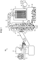
- FIG. 1 is a schematic view of a feather separation system 100 according to an embodiment.
- the feather separation system 100 for separating feathers from a product 1 in which feathers are filled into a bag-shaped product of a covering 3 includes a cutting part 10 for cutting the product 1 into individual pieces so that at least a part of the bag-shaped product of the covering 3 is open; a feather separation part 20 for separating the individual pieces into feathers 2 and the covering 3; a conveying part 30 for conveying the individual pieces cut in the cutting part 10 to the feather separation part; a feather collection part 40 for storing the separated feathers 2; a covering collection part 50 for storing the separated covering 3; and an airflow introduction part 60 for introducing airflow to the feather separation part.
- the feathers to be separated by the feather separation system 100 are feathers that are filled in a bag-shaped product of the covering.
- bedding and clothing can be exemplified.
- the covering is sewn or joined together with an adhesive to a predetermined size in order to reduce uneven distribution of the feathers and a predetermined amount of the feathers are filled in the bag-shaped product of the covering formed by the sewing or joining.
- the feathers that are the target of separation in this embodiment are feathers that are filled in a bag-shaped covering formed by sewing or joining.
- the cutting part 10 includes a cutter 11 and a conveying part 12.
- the cutter 11 may be a cutter for individualizing the product 1 in one stage or a cutter for cutting the product 1 in two stages in a longitudinal direction and a transverse direction.
- a constitution in which the conveying part 12 is arranged in an L-shape and the product is cut in a longitudinal direction or a transverse direction, thereafter the conveying direction is changed by 90°, and thereafter the cut product is cut in the transverse direction or the longitudinal direction is preferable from the viewpoint of space saving.
- the cutting part 10 cuts the product 1 into individual pieces so that a part of the bag-shaped product of the covering 3 opens. Separation of the feathers 2 is possible as long as at least a part of the bag-shaped product of the covering 3 opens.
- the product 1 is preferably cut so that two sides of the bag-shaped product open.
- the area S of the covering cut into pieces is preferably larger than 1 cm 2 and smaller than 400 cm 2 and further preferably larger than 10 cm 2 and smaller than 100 cm 2 from the viewpoint of collection ratio.
- the area S of the covering is defined as an area in a state where the cut covering is spread as much as possible on a flat plate.
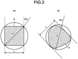
- the covering is preferably cut so that D/L is in the range of D/L ⁇ 10 and further preferably cut so that D/L is in the range of D/L ⁇ 4 where D is the diameter of the smallest circumscribed circle of the cut covering and L is the distance between the smallest circumscribed parallel lines. Reducing the ratio of the diameter D of the smallest circumscribed circle of the covering and the distance L between the smallest circumscribed parallel lines allows entanglement of the covering on a rotating shaft 25 and stirring rods 26 to be prevented.
- FIG. 2 is a view illustrating the cutting of the covering.
- FIG. 2(a) illustrates the case where the individual piece P of the cut covering is rectangular
- FIG. 2(b) illustrates the case where individual piece P is other than rectangular.
- the area S of the individual piece P of the cut covering is preferably cut to a size that is 10% or more and 100% or less of the area of a single unit of the bag-shaped product when the area S is represented relative to the area of the bag-shaped product.
- the feather separation part 20 includes a separation tank 21 having a cylindrical shape with an inner cavity in at least a part, a feather charge part 22 for charging the cut and individualized product 1, a feather discharge part 23 for discharging the separated feathers 2 from the covering 3, a rotating shaft 25 located in the center of the cylinder of the separation tank 21 and having a plurality of stirring rods 26 at different positions in a height direction, and a covering discharge part 24 for discharging the separated covering 3.
- the feather separation part 20 separates the feathers 2 covered with the covering 3 from the covering 3 by striking the individual pieces, that is, the covering 3 in which the feathers 2 are filled falls by its own weight with the rotating stirring rods 26 by rotating the rotating shaft 25.
- the feathers 2 are stuck to the covering 3 by static electricity or filled in the bag-shaped product of the covering 3 and thus can be separated from the covering 3 by mechanically striking with the stirring rods 26.
- the separation tank 21 preferably has a predetermined height.
- the height of the separation tank 21 is preferably twice or more of the diameter of the separation tank 21 and more preferably three times or more of the diameter.
- An excessively high height of the separation tank 21 results in large equipment, does not allow the tank to be installed in a space-saving manner, and causes difficulty in maintenance and cleaning. Consequently, the height is more preferably 5 times or less and further preferably 4 times or less of the diameter.
- the feather charge part 22 is located above the center of the separation tank 21 in the height direction. Locating the feather charge part 22 on the upper part wall of the separation tank 21 in the height direction allows the stirring rods 26 to strike individual pieces for a given time without increasing the air velocity of the airflow introduced into the separation tank 21 and thus the collection ratio and the down ratio to be improved.
- the feather discharge part 23 is located at the upper part of the separation tank 21.
- the covering discharge part 24 is located at the lower part of the separation tank 21.
- the feathers 2 have a lower specific gravity than the covering 3 and thus the feathers 2 separated from the covering 3 are carried to the upper part of the separation tank 21 by the airflow flowing from the lower part to the upper part in the separation tank 21 and discharged from the feather discharge part 23.
- the covering 3 having a higher specific gravity falls to the lower part of the separation tank 21 due to its own weight and is discharged from the covering discharge part 24.
- the feather discharge part 23 is preferably arranged in the center of the upper surface of the separation tank 21.
- Centrifugal force acts by the rotation of the rotating shaft 25 and the covering 3 having a higher specific gravity is blown to the outsides of the cylinder and effectively falls down.
- the airflow is formed in the center side of the separation tank 21 and thus the feathers 2 separated from the covering 3 can be effectively discharged from the feather discharge part 23 arranged at the center of the separation tank 21 by riding on this airflow.
- the stirring rods 26 are attached to the rotating shaft 25 at different positions.
- two stirring rods 26 extend in a straight line at the same height and opposite each other using the rotating shaft 25 as the center.
- the stirring rods 26 extend from the rotating shaft 25 so as to be orthogonal (rotated 90°) to the stirring rod 26 at the adjacent height.
- frequent mechanical contact is preferably performed with the stirring rods 26. Therefore, the stirring rods 26 attached to the rotating shaft 25 are not limited to two rods at the same height.
- the extending stirring rods 26 may be arranged so that the three rods are arranged at the same height forming an angle of 120° or four rods are arranged at orthogonal angles.
- the stirring rods 26 are preferably arranged so as not to overlap with stirring rods 26 arranged at an adjacent height. An excessively large number of the stirring rods 26 arranged at the same position may cause airflow generated in the separation tank 21 to be obstructed. Therefore, the number of the stirring rods 26 attached to the same position of the rotating shaft 25 is preferably set to 8 or less.
- the stirring rods 27 are not required to be a rod-shaped rigid body and may be rods attached to the rotating shaft 25, deformed by the action of centrifugal force while the rotating shaft 25 is rotating, and rotating in a state where the rods radially extend approximately perpendicular to the rotating shaft 25.
- the covering 3 covering the feathers 2 that is in mechanical contacted with the stirring rods 26 and the covering 3 separated from the feathers 2 may be bounced up to the upper part of the separation tank 21 due to mechanical contact with the stirring rods 26.
- at least one pair of stirring rods are attached to above the feather charge part 22.
- the rotating diameter of the stirring rods 26 (Diameter of rotating shaft 25 + Length of stirring rod 26 ⁇ 2) is preferably 80% or more, more preferably 90% or more, and further preferably 95% or more of the diameter of the cylinder constituting the separation tank 21. In order to avoid interference with the separation tank 21, the rotating diameter of the stirring rod 26 is 99% or less and preferably 98% or less of the diameter of the cylinder.
- the stirring rods 26 arranged at a lowermost part function as scraping rods 26a that scrape out the covering 3 separated from the feathers 2.
- the scraping rods 26a are preferably attached at the lowermost part where the scraping rods 26a do not come into contact with the bottom surface of the separation tank 21.
- the rotation speed of the rotating shaft 25 can be appropriately selected depending on the cut size of the covering 3 and the speed of the airflow and is preferably 100 rpm or more and more preferably 400 rpm or more. Increasing the rotation speed of the rotating shaft 25 allows the number of contacts between the stirring rods 26 and the covering 3 to increase and thus the separation efficiency to be improved.
- the upper limit is preferably 1,000 rpm or less from the viewpoint of consumption energy and efficiency.
- the feather collection part 40 includes a collection tank 41 for storing the feathers 2, a charge part 42 that is provided above the collection tank and in which the separated feathers 2 are charged, and a ventilation opening 43 that connects an airflow introduction part 60 described below.
- the charge part 42 of the feather collection part 40 is connected to the feather discharge part 23 of the feather separation part 20 by a pipe 44 or other means.
- one collection tank 41 exists.
- a constitution in which two collection tanks 41 are alternately used by providing a three-way valve in the pipe 44 may be adopted.
- the covering collection part 50 includes a storing part 51 for storing the covering 3 and a charge part 52 for charging the separated covering 3.
- the covering collection part 50 is preferably arranged at the lower part of the feather separation part 20.
- the airflow introduction part 60 that introduces the airflow into the separation tank 21 of the feather separation part 20 is attached to the ventilation opening 43 of the feather collection part 40, as illustrated in FIG. 1 as an example.
- a suction blower or a similar device can be used as the airflow introduction part 60.
- the airflow introduction part is arranged at the ventilation opening 43 of the feather collection part 40 and may also be provided in the pipe 44 that connects the feather separation part 20 and the feather collection part 40.
- FIG. 3 is a schematic diagram of the feather separation system 100D according to Modified Example 1 of this embodiment. As illustrated in FIG. 3 , a blowing fan may be provided at the lower part of the separation tank 21 as an airflow introduction part 61.
- the velocity of the airflow introduced into the separation tank 21 by the airflow introduction part 60 is defined as a value obtained by dividing the total airflow through the separation tank by a cylindrical-shaped cross-sectional area constituting the separation tank 21 and is preferably 0.1 m/sec or more and 1.0 m/sec or less. As the velocity of the airflow becomes lower, the ratio of down in the feathers 2 discharged from the feather discharge part 23 becomes larger. On the other hand, an excessively low air velocity causes the airflow capacity of the separated feathers 2 to be lowered and thus the collection ratio of the feathers 2 per hour to be lowered. Conversely, an excessively high air velocity may increase possibility that the discharged feathers are mixed with the separated covering.
- the velocity of the airflow introduced into the separation tank 21 is further preferably 0.3 m/sec or more and 0.5 m/sec or less.
- the individual pieces of product 1 formed by cutting in the cutting part 10 are conveyed by the conveying part 30 to the feather charge part 22 in the feather separation part 20.
- a constitution in which the individual pieces are directly charged from the cutting part 10 to the feather charge part 22 without using the conveying part 30 may also be adopted.
- the feather separation system 100 cuts the product 1 in the cutting part 10 and automatically conveys the cut product to the feather separation part 20 by the conveying part 30 to separate and collect the feathers. Therefore, the feathers 2 can be efficiently collected from the product 1 with a compact system.
- the feathers 2 alone can be continuously and effectively separated even in a system having a relatively small separation tank 21 by mechanically contacting the feathers 2 covered with the covering 3 with the stirring rods 26 and separating from the covering 3 by striking to effectively form a mixing state where the covering 3 and the feathers 2 are surely separated and by flowing airflow that can float the feathers alone in the feather separation part 20.
- a feather separation system equipped with the cutting part, the feather separation part, and the airflow introduction part is preferable.
- the feathers can be separated and collected from the individual pieces in which at least a part of the covering opens.
- FIG. 4 is a cross-sectional view of a feather separation part 20A in a feather separation system according to Modified Example 2 of the embodiment in a vertical direction.
- FIG. 4 and the following description of the feather separation part 20A the same signs are assigned and description is omitted for constitutions similar to the embodiment.
- the feather separation part 20A includes a separation tank 21A made of a cylinder, a feather charge part 22, a feather discharge part 23, a rotating shaft 25 having a plurality of stirring rods 26 at different positions, and a covering discharge part 24.
- the separation tank 21A is arranged so that the rotating shaft 25 is obliquely arranged. Arranging the separation tank 21A so that the rotating shaft 25 is oblique results in the longer falling time of the covering 3 that covers the feathers 2 and thus the number of mechanical contacts with the stirring rods 26 is also increased. This can improve separation efficiency.
- the inclination angle of the rotating shaft 25 is preferably 15° or more and 80° or less from the horizontal direction and further preferably 30° or more and 60° or less from the horizontal direction.
- FIG. 5A is a cross-sectional view of a feather separation part 20B in a feather separation system according to Modified Example 3 of the embodiment in a vertical direction.
- FIG. 5B is a cross-sectional view in a vertical direction orthogonal to the cross-section illustrated in FIG. 5A .
- FIG. 5C is a top view of a separation tank 21B in FIG. 5A .
- FIG. 5A to FIG. 5C and in the following description of the feather separation part 20B the same signs are assigned and description is omitted for constitutions similar to the embodiment.
- the separation tank 21B has a shape formed by joining two cylinders at the sides of the two cylinders, that is, a cocoon shape and the rotating shaft 25 is located at the center of each of the two cylinders.
- a distance between the centers of the cylinders, that is, a distance between the rotating shafts 25 arranged at the centers of the cylinders is preferably 70% or more and 90% or less of the cylinder inner diameter of the stirring rods 26.
- the stirring rods 26 attached to each of the rotating shafts 25 are attached at different heights so as to avoid interfering with each other.
- Forming the separation tank 21B in the cocoon shape and providing the respective rotating shafts 25 at the center of each of the two cylinders allow the separation efficiency to be more improved.
- Rotating the rotating shafts 25 in the same direction in each of the cylinders allows the stirring rods 26 to move each other in opposite directions near the position where the cylinders are connected. A particularly high stirring effect acts around this position and the efficiency of separation is further improved.
- FIG. 6 is a cross-sectional view of a feather separation part 20C in a feather separation system according to Modified Example 4 of the embodiment in a vertical direction.
- the same signs are assigned and description is omitted for constitutions similar to the embodiment.
- a feather separation part 20C includes a separation tank 21C including one cylinder, a feather charge part 22 attached to the upper part of the separation tank 21C, a feather discharge part 23 attached to the lower part of the separation tank 21C, a rotating shaft 25 having a plurality of stirring rods 26 at different positions, a covering discharge part 24, and a collection part 50 for collecting the covering discharged from the covering discharge part 24.
- the separation tank 21C is arranged so that the rotating shaft 25 is obliquely arranged.
- the feather charge part 22 includes a blowing means for introducing the airflow into the separation tank 21C and functions as a blowing part.
- the separation tank 21C is arranged so that the rotating shaft is oblique and the feather discharge part 23 is provided at the lower part of the separation tank 21C that is the downstream side of the airflow. In the case of such a constitution, the feathers to be separated from the covering are also efficiently separated.
- the feather separation system according to the present invention can be suitably used in the case where feathers used as the filling for bedding or clothing are recycled.
- a feather separation method using this system allows the feathers to be efficiently separated.
- the recycled feathers can be efficiently produced.
- the invention is not limited to Examples described below.
- the feather separation part of the feather separation system used in Examples described below has the structures illustrated in FIGS. 5A to 5C .
- five long-sleeved down jackets having a size with a width of about 5 cm to about 6 cm and a length of about 15 cm to about 50 cm in which bag-shaped products are arranged at arm parts and a body part are used.
- the feathers used in the down jackets are feathers having a down ratio of 90%.
- a cutting part includes a shear cutter and has a structure in which the down jackets are vertically and horizontally cut in two stages.
- the individual pieces cut in the cutting part were charged into the feather separation part having the structure illustrated in FIGS. 5A to 5C in a proportion of 1500 g/min (feathers: 300 g and covering and others: 1200 g).
- the feather separation part has the following structure.
- the cutting size of the down jackets was varied from 10 mm square to 100 mm square and the feathers covered with the down jacket fabric were separated by the feather separation system described above.
- the system was operated at a rotational speed of the stirring rods of 800 rpm and an air velocity of the airflow of 0.3 m/sec. Performance was evaluated by a collection ratio, a down ratio, and an amount of contamination other than feathers. The results are listed in Table 1.
- the down jacket cut size was fixed at 50 mm square, the air velocity of the airflow was fixed at 0.3 m/sec, and the rotation speed of the stirring rods was varied from 100 rpm to 1000 rpm to separate the feathers.
- the results are listed in Table 2.
- the down jacket cut size was fixed at 50 mm square, the rotation speed of the stirring rods was fixed at 800 rpm, and the air velocity of the airflow was varied from 0.1 m/sec to 0.7 m/sec to separate the feathers.
- the results are listed in Table 3.
Landscapes
- Engineering & Computer Science (AREA)
- Mechanical Engineering (AREA)
- Processing Of Solid Wastes (AREA)
- Combined Means For Separation Of Solids (AREA)
- Chemical Or Physical Treatment Of Fibers (AREA)
- Accessories For Mixers (AREA)
- Mixers Of The Rotary Stirring Type (AREA)
- Preliminary Treatment Of Fibers (AREA)
Abstract
Description
- The present invention relates to a feather separation system and a feather separation method that separate feathers from a product in which feathers are filled and a method for producing recycled feathers. Background
- Feathers are used as bedding and clothing fillings. Feathers used for the bedding are reused by cutting and breaking down the bedding that is manually hung and thereafter vacuuming and collecting the feathers in the bedding when the feathers are recycled. However, this process has a problem in collection efficiency and working environment due to scatter of the feathers. On the other hand, in clothing or the like, the amount of used feathers is small and thus manual separation and collection of the feathers are inefficient. Therefore, these feathers are difficult to reuse.
- In recent years, the efficient reuse of feathers used for the bedding and the clothing is aspired from the viewpoints of environment and ethics. Although techniques for separating down and non-down feathers from feathers have been developed (for example, refer to Patent Literatures 1 to 3), no study has been conducted for techniques to efficiently collect the feathers covered with a covering such as fabrics.
-
- Patent Literature 1:
Japanese Patent Application Laid-open No. S62-137087 - Patent Literature 2:
Japanese Patent No. 4936014 - Patent Literature 3:
Chinese Utility Model No. 204281925 - The present invention is made in view of the above situation and an object of the present invention is to provide a feather separation system and a feather separation method that efficiently separate and collect feathers from products in which the feathers are filled into a bag-shaped product of a covering and a method for producing recycled feathers.
- To solve the problem described above and to achieve the object, a feather separation system according to the present invention is a feather separation system for separating feathers from a product in which feathers are filled into a bag-shaped product of a covering. The feather separation system includes: a cutting part configured to cut the product into individual pieces so that at least a part of the bag-shaped product of the covering is open; a feather separation part configured to separate the individual pieces of the product into the feathers and the covering; and an airflow introduction part configured to introduce airflow to the feather separation part.
- The feather separation system according to the present invention further includes: a feather collection part configured to store the separated feathers; and a covering collection part configured to store the separated covering.
- In the feather separation system according to the present invention, the cutting part is configured to cut the covering of the product so that an area S of the covering of the product is larger than 1 cm2 and less than 400 cm2, and D/L is in a range of D/L < 10 where D is a diameter of a smallest circumscribed circle of the individual pieces of the cut covering and L is a distance between smallest circumscribed parallel lines of the individual pieces of the cut covering.
- In the feather separation system according to the present invention, the feather separation part includes a separation tank having a cylindrical shape at least in a part of the separation tank, a feather charge part configured to charge the cut individual pieces, a feather discharge part configured to discharge the separated feathers, a rotating shaft located at a center of a cylinder of the separation tank, the rotating shaft including a plurality of stirring rods at different positions in a height direction, and a covering discharge part configured to discharge the separated covering.
- In the feather separation system according to the present invention, the stirring rods are provided at least at a lower part lower than the feather charge part.
- In the feather separation system according to the present invention, the separation tank has a shape formed by joining two cylinders at sides of the two cylinders and the rotating shaft is provided at each center of the two cylinders.
- In the feather separation system according to the present invention, a rotation speed of the rotating shaft is 100 rpm or more and 1000 rpm or less.
- In the feather separation system according to the present invention, a stirring rod having a function of preventing the covering from mixing into the feather discharge part are provided at an upper part of the rotating shaft above the feather charge part.
- In the feather separation system according to the present invention, a stirring rod arranged at a lowermost part among the stirring rods is a scraping rod for the covering separated from the feathers.
- In the feather separation system according to the present invention, the separation tank is obliquely arranged so that the rotating shaft forms an angle of 15° to 80° from a horizontal direction.
- In the feather separation system according to the present invention, the airflow introduction part is configured to introduce airflow having a velocity of 0.1 m/second or more and 1.0 m/second or less inside the separation tank.
- In the feather separation system according to the present invention, the airflow introduction part is connected to the feather collection part.
- A feather separation method according to the present invention is a feather separation method for separating feathers from a product in which feathers are filled in a bag-shaped product of a covering. The feather separation method includes: a cutting step of cutting the product into individual pieces so that at least a part of the bag-shaped product of the covering is open; a feather separating step of separating the individual pieces of the product into the feathers and the covering by a stirring means and airflow; and a feather collecting step of collecting the separated feathers.
- In the feather separation method according to the present invention, the separation step includes carrying feathers alone together with flow of air from a separation tank by forming a mixed state made of the covering, the feathers, and air with the stirring means in the separation tank and introducing the airflow in the separation tank.
- In the feather separation method according to the present invention, the cutting step includes cutting the covering of the product so that an area S of the covering of the product is more than 1 cm2 and less than 400 cm2, and D/L is in a range of D/L < 10 where D is a diameter of a smallest circumscribed circle of the individual pieces of the cut covering and L is a distance between smallest circumscribed parallel lines of the individual pieces of the cut covering.
- In the feather separation method according to the present invention, the feather separation step includes separating the feathers by introducing the airflow having a velocity of 0.1 m/second or more and 1.0 m/second or less.
- A method for producing recycle feathers according to the present invention includes the feather separation method.
- According to the present invention, feathers can be continuously and efficiently separated in a feather separation part from a product that is broken into individual pieces in a cutting part and feathers having a high down ratio can be collected.
- According to the present invention, the feathers stuck to the covering due to static electricity or the like and the feathers filled in the covering can be efficiently beaten out and separated by mechanically striking the feathers covered with the covering using stirring rods attached to a rotating shaft.
-
-
FIG. 1 is a schematic view of a feather separation system according to an embodiment. -
FIG. 2 is a view illustrating cutting of a covering. -
FIG. 3 is a schematic view of a feather separation system according to Modified Example 1 of the embodiment. -
FIG. 4 is a cross-sectional view of a feather separation part in a feather separation system according to Modified Example 2 of the embodiment in a vertical direction. -
FIG. 5A is a cross-sectional view of a feather separation part in a feather separation system according to Modified Example 3 of the embodiment in a vertical direction. -
FIG. 5B is a cross-sectional view in a vertical direction orthogonal to the cross-section illustrated inFIG. 5A . -
FIG. 5C is a top view ofFIG. 5A . -
FIG. 6 is a cross-sectional view of a feather separation part in a feather separation system according to Modified Example 4 of the embodiment in a vertical direction. - Hereinafter, embodiments for implementing the present invention (hereinafter, refers to as "embodiments") will be described with reference to the attached drawings. It should be noted that the drawings are only schematic views and the shapes, sizes, and positional relations are schematically illustrated to the extent that the contents of the present invention can be understood. In other words, the present invention is not limited only to the shapes, sizes, and positional relations illustrated in each of the drawings. In addition, parts that differ from each other in dimensions and proportions among the reciprocal drawings are included.
-
FIG. 1 is a schematic view of afeather separation system 100 according to an embodiment. Thefeather separation system 100 for separating feathers from a product 1 in which feathers are filled into a bag-shaped product of acovering 3 includes acutting part 10 for cutting the product 1 into individual pieces so that at least a part of the bag-shaped product of thecovering 3 is open; afeather separation part 20 for separating the individual pieces intofeathers 2 and thecovering 3; a conveyingpart 30 for conveying the individual pieces cut in thecutting part 10 to the feather separation part; afeather collection part 40 for storing theseparated feathers 2; acovering collection part 50 for storing theseparated covering 3; and anairflow introduction part 60 for introducing airflow to the feather separation part. - The feathers to be separated by the
feather separation system 100 according to this embodiment are feathers that are filled in a bag-shaped product of the covering. As the product 1 in which feathers are filled in the bag-shaped product of the covering, bedding and clothing can be exemplified. Generally, when feathers are used as filling for bedding or clothing, the covering is sewn or joined together with an adhesive to a predetermined size in order to reduce uneven distribution of the feathers and a predetermined amount of the feathers are filled in the bag-shaped product of the covering formed by the sewing or joining. The feathers that are the target of separation in this embodiment are feathers that are filled in a bag-shaped covering formed by sewing or joining. - The cutting
part 10 includes acutter 11 and a conveyingpart 12. Thecutter 11 may be a cutter for individualizing the product 1 in one stage or a cutter for cutting the product 1 in two stages in a longitudinal direction and a transverse direction. In the case where thecutter 11 cuts the product 1 in two stages, a constitution in which the conveyingpart 12 is arranged in an L-shape and the product is cut in a longitudinal direction or a transverse direction, thereafter the conveying direction is changed by 90°, and thereafter the cut product is cut in the transverse direction or the longitudinal direction is preferable from the viewpoint of space saving. - The cutting
part 10 cuts the product 1 into individual pieces so that a part of the bag-shaped product of thecovering 3 opens. Separation of thefeathers 2 is possible as long as at least a part of the bag-shaped product of thecovering 3 opens. The product 1 is preferably cut so that two sides of the bag-shaped product open. With respect to the covering, the area S of the covering cut into pieces is preferably larger than 1 cm2 and smaller than 400 cm2 and further preferably larger than 10 cm2 and smaller than 100 cm2 from the viewpoint of collection ratio. The area S of the covering is defined as an area in a state where the cut covering is spread as much as possible on a flat plate. The covering is preferably cut so that D/L is in the range of D/L < 10 and further preferably cut so that D/L is in the range of D/L < 4 where D is the diameter of the smallest circumscribed circle of the cut covering and L is the distance between the smallest circumscribed parallel lines. Reducing the ratio of the diameter D of the smallest circumscribed circle of the covering and the distance L between the smallest circumscribed parallel lines allows entanglement of the covering on arotating shaft 25 and stirringrods 26 to be prevented.FIG. 2 is a view illustrating the cutting of the covering.FIG. 2(a) illustrates the case where the individual piece P of the cut covering is rectangular, whereasFIG. 2(b) illustrates the case where individual piece P is other than rectangular. Keeping the ratio of the diameter D of the smallest circumscribed circle and the distance L between the smallest circumscribed parallel lines of the individual piece P of the covering low allows the entanglement of the covering on therotating shaft 25 and stirringrods 26 to be prevented and the opportunity to cut down to be reduced. The area S of the individual piece P of the cut covering is preferably cut to a size that is 10% or more and 100% or less of the area of a single unit of the bag-shaped product when the area S is represented relative to the area of the bag-shaped product. - The
feather separation part 20 includes aseparation tank 21 having a cylindrical shape with an inner cavity in at least a part, afeather charge part 22 for charging the cut and individualized product 1, afeather discharge part 23 for discharging the separatedfeathers 2 from thecovering 3, a rotatingshaft 25 located in the center of the cylinder of theseparation tank 21 and having a plurality of stirringrods 26 at different positions in a height direction, and acovering discharge part 24 for discharging the separated covering 3. - The
feather separation part 20 separates thefeathers 2 covered with the covering 3 from thecovering 3 by striking the individual pieces, that is, thecovering 3 in which thefeathers 2 are filled falls by its own weight with therotating stirring rods 26 by rotating therotating shaft 25. Thefeathers 2 are stuck to thecovering 3 by static electricity or filled in the bag-shaped product of thecovering 3 and thus can be separated from thecovering 3 by mechanically striking with the stirringrods 26. - In order to efficiently separate the
feathers 2 and thecovering 3, theseparation tank 21 preferably has a predetermined height. The height of theseparation tank 21 is preferably twice or more of the diameter of theseparation tank 21 and more preferably three times or more of the diameter. An excessively high height of theseparation tank 21 results in large equipment, does not allow the tank to be installed in a space-saving manner, and causes difficulty in maintenance and cleaning. Consequently, the height is more preferably 5 times or less and further preferably 4 times or less of the diameter. - The
feather charge part 22 is located above the center of theseparation tank 21 in the height direction. Locating thefeather charge part 22 on the upper part wall of theseparation tank 21 in the height direction allows the stirringrods 26 to strike individual pieces for a given time without increasing the air velocity of the airflow introduced into theseparation tank 21 and thus the collection ratio and the down ratio to be improved. - The
feather discharge part 23 is located at the upper part of theseparation tank 21. Thecovering discharge part 24 is located at the lower part of theseparation tank 21. Thefeathers 2 have a lower specific gravity than thecovering 3 and thus thefeathers 2 separated from thecovering 3 are carried to the upper part of theseparation tank 21 by the airflow flowing from the lower part to the upper part in theseparation tank 21 and discharged from thefeather discharge part 23. On the other hand, thecovering 3 having a higher specific gravity falls to the lower part of theseparation tank 21 due to its own weight and is discharged from the coveringdischarge part 24. Thefeather discharge part 23 is preferably arranged in the center of the upper surface of theseparation tank 21. Centrifugal force acts by the rotation of therotating shaft 25 and thecovering 3 having a higher specific gravity is blown to the outsides of the cylinder and effectively falls down. The airflow is formed in the center side of theseparation tank 21 and thus thefeathers 2 separated from thecovering 3 can be effectively discharged from thefeather discharge part 23 arranged at the center of theseparation tank 21 by riding on this airflow. - The stirring
rods 26 are attached to therotating shaft 25 at different positions. In this embodiment, two stirringrods 26 extend in a straight line at the same height and opposite each other using the rotatingshaft 25 as the center. The stirringrods 26 extend from the rotatingshaft 25 so as to be orthogonal (rotated 90°) to the stirringrod 26 at the adjacent height. In order to efficiently separate thefeathers 2 covered with thecovering 3, frequent mechanical contact is preferably performed with the stirringrods 26. Therefore, the stirringrods 26 attached to therotating shaft 25 are not limited to two rods at the same height. The extendingstirring rods 26 may be arranged so that the three rods are arranged at the same height forming an angle of 120° or four rods are arranged at orthogonal angles. Even when the number of stirringrods 26 attached at the same position is increased, the stirringrods 26 are preferably arranged so as not to overlap with stirringrods 26 arranged at an adjacent height. An excessively large number of the stirringrods 26 arranged at the same position may cause airflow generated in theseparation tank 21 to be obstructed. Therefore, the number of the stirringrods 26 attached to the same position of therotating shaft 25 is preferably set to 8 or less. The stirring rods 27 are not required to be a rod-shaped rigid body and may be rods attached to therotating shaft 25, deformed by the action of centrifugal force while the rotatingshaft 25 is rotating, and rotating in a state where the rods radially extend approximately perpendicular to therotating shaft 25. - In this embodiment, six pairs of the stirring
rods 26 are attached at different heights. Thecovering 3 covering thefeathers 2 that is in mechanical contacted with the stirringrods 26 and thecovering 3 separated from thefeathers 2 may be bounced up to the upper part of theseparation tank 21 due to mechanical contact with the stirringrods 26. In order to prevent thecovering 3 that covers thefeathers 2 and thecovering 3 separated from thefeathers 2 from being discharged from thefeather discharge part 23, at least one pair of stirring rods are attached to above thefeather charge part 22. - As the length of the stirring
rods 26 becomes longer, the stirringrods 26 become preferable because the number of contacts with thefeathers 2 covered with thecovering 3 increases. The rotating diameter of the stirring rods 26 (Diameter ofrotating shaft 25 + Length of stirringrod 26 × 2) is preferably 80% or more, more preferably 90% or more, and further preferably 95% or more of the diameter of the cylinder constituting theseparation tank 21. In order to avoid interference with theseparation tank 21, the rotating diameter of the stirringrod 26 is 99% or less and preferably 98% or less of the diameter of the cylinder. - Of the stirring
rods 26 attached to therotating shaft 25, the stirringrods 26 arranged at a lowermost part function as scrapingrods 26a that scrape out thecovering 3 separated from thefeathers 2. The scrapingrods 26a are preferably attached at the lowermost part where thescraping rods 26a do not come into contact with the bottom surface of theseparation tank 21. - In this embodiment, the rotation speed of the
rotating shaft 25 can be appropriately selected depending on the cut size of thecovering 3 and the speed of the airflow and is preferably 100 rpm or more and more preferably 400 rpm or more. Increasing the rotation speed of therotating shaft 25 allows the number of contacts between the stirringrods 26 and thecovering 3 to increase and thus the separation efficiency to be improved. The upper limit is preferably 1,000 rpm or less from the viewpoint of consumption energy and efficiency. - The
feather collection part 40 includes acollection tank 41 for storing thefeathers 2, acharge part 42 that is provided above the collection tank and in which the separatedfeathers 2 are charged, and aventilation opening 43 that connects anairflow introduction part 60 described below. Thecharge part 42 of thefeather collection part 40 is connected to thefeather discharge part 23 of thefeather separation part 20 by apipe 44 or other means. In this embodiment, onecollection tank 41 exists. However, a constitution in which twocollection tanks 41 are alternately used by providing a three-way valve in thepipe 44 may be adopted. - The covering
collection part 50 includes a storingpart 51 for storing thecovering 3 and acharge part 52 for charging the separated covering 3. In order to collect the covering 3 from the coveringdischarge part 24 by the own weight of thecovering 3, the coveringcollection part 50 is preferably arranged at the lower part of thefeather separation part 20. - The
airflow introduction part 60 that introduces the airflow into theseparation tank 21 of thefeather separation part 20 is attached to theventilation opening 43 of thefeather collection part 40, as illustrated inFIG. 1 as an example. In this case, a suction blower or a similar device can be used as theairflow introduction part 60. In this embodiment, the airflow introduction part is arranged at theventilation opening 43 of thefeather collection part 40 and may also be provided in thepipe 44 that connects thefeather separation part 20 and thefeather collection part 40.FIG. 3 is a schematic diagram of thefeather separation system 100D according to Modified Example 1 of this embodiment. As illustrated inFIG. 3 , a blowing fan may be provided at the lower part of theseparation tank 21 as anairflow introduction part 61. - The velocity of the airflow introduced into the
separation tank 21 by theairflow introduction part 60 is defined as a value obtained by dividing the total airflow through the separation tank by a cylindrical-shaped cross-sectional area constituting theseparation tank 21 and is preferably 0.1 m/sec or more and 1.0 m/sec or less. As the velocity of the airflow becomes lower, the ratio of down in thefeathers 2 discharged from thefeather discharge part 23 becomes larger. On the other hand, an excessively low air velocity causes the airflow capacity of the separatedfeathers 2 to be lowered and thus the collection ratio of thefeathers 2 per hour to be lowered. Conversely, an excessively high air velocity may increase possibility that the discharged feathers are mixed with the separated covering. The velocity of the airflow introduced into theseparation tank 21 is further preferably 0.3 m/sec or more and 0.5 m/sec or less. - In this embodiment, the individual pieces of product 1 formed by cutting in the cutting
part 10 are conveyed by the conveyingpart 30 to thefeather charge part 22 in thefeather separation part 20. However, a constitution in which the individual pieces are directly charged from the cuttingpart 10 to thefeather charge part 22 without using the conveyingpart 30 may also be adopted. - As described above, the
feather separation system 100 according to this embodiment cuts the product 1 in the cuttingpart 10 and automatically conveys the cut product to thefeather separation part 20 by the conveyingpart 30 to separate and collect the feathers. Therefore, thefeathers 2 can be efficiently collected from the product 1 with a compact system. Thefeathers 2 alone can be continuously and effectively separated even in a system having a relativelysmall separation tank 21 by mechanically contacting thefeathers 2 covered with thecovering 3 with the stirringrods 26 and separating from thecovering 3 by striking to effectively form a mixing state where thecovering 3 and thefeathers 2 are surely separated and by flowing airflow that can float the feathers alone in thefeather separation part 20. In order to efficiently separate and collect the feathers from the product, a feather separation system equipped with the cutting part, the feather separation part, and the airflow introduction part is preferable. However, in a feather separation apparatus in which the airflow introduction part is directly connected to the feather separation part as the feather separation part of Modified Example illustrated inFIG. 3 , the feathers can be separated and collected from the individual pieces in which at least a part of the covering opens. - In the above embodiment, the
feather separation part 20 is arranged so that the rotatingshaft 25 overlaps the vertical direction (an angle of 90° with respect to the horizontal direction). The present invention, however, is not limited thereto.FIG. 4 is a cross-sectional view of afeather separation part 20A in a feather separation system according to Modified Example 2 of the embodiment in a vertical direction. InFIG. 4 and the following description of thefeather separation part 20A, the same signs are assigned and description is omitted for constitutions similar to the embodiment. - The
feather separation part 20A includes aseparation tank 21A made of a cylinder, afeather charge part 22, afeather discharge part 23, a rotatingshaft 25 having a plurality of stirringrods 26 at different positions, and acovering discharge part 24. In thefeather separation part 20A, theseparation tank 21A is arranged so that the rotatingshaft 25 is obliquely arranged. Arranging theseparation tank 21A so that the rotatingshaft 25 is oblique results in the longer falling time of thecovering 3 that covers thefeathers 2 and thus the number of mechanical contacts with the stirringrods 26 is also increased. This can improve separation efficiency. The inclination angle of therotating shaft 25 is preferably 15° or more and 80° or less from the horizontal direction and further preferably 30° or more and 60° or less from the horizontal direction. - In the above embodiment, the
separation tank 21 of thefeather separation part 20 is constituted of one cylinder. However, theseparation tank 21 may also be made of two cylinders joined at the sides.FIG. 5A is a cross-sectional view of afeather separation part 20B in a feather separation system according to Modified Example 3 of the embodiment in a vertical direction.FIG. 5B is a cross-sectional view in a vertical direction orthogonal to the cross-section illustrated inFIG. 5A .FIG. 5C is a top view of aseparation tank 21B inFIG. 5A . InFIG. 5A to FIG. 5C and in the following description of thefeather separation part 20B, the same signs are assigned and description is omitted for constitutions similar to the embodiment. - In the
feather separation part 20B, theseparation tank 21B has a shape formed by joining two cylinders at the sides of the two cylinders, that is, a cocoon shape and therotating shaft 25 is located at the center of each of the two cylinders. In the two cylinders, a distance between the centers of the cylinders, that is, a distance between therotating shafts 25 arranged at the centers of the cylinders is preferably 70% or more and 90% or less of the cylinder inner diameter of the stirringrods 26. In addition, the stirringrods 26 attached to each of therotating shafts 25 are attached at different heights so as to avoid interfering with each other. Forming theseparation tank 21B in the cocoon shape and providing the respectiverotating shafts 25 at the center of each of the two cylinders allow the separation efficiency to be more improved. Rotating therotating shafts 25 in the same direction in each of the cylinders allows the stirringrods 26 to move each other in opposite directions near the position where the cylinders are connected. A particularly high stirring effect acts around this position and the efficiency of separation is further improved. - In addition, in the above embodiment, the
feather discharge part 23 is arranged at the upper part of theseparation tank 21B. However, the arrangement is not limited thereto.FIG. 6 is a cross-sectional view of afeather separation part 20C in a feather separation system according to Modified Example 4 of the embodiment in a vertical direction. InFIG. 6 and the following description of thefeather separation part 20C, the same signs are assigned and description is omitted for constitutions similar to the embodiment. - A
feather separation part 20C includes aseparation tank 21C including one cylinder, afeather charge part 22 attached to the upper part of theseparation tank 21C, afeather discharge part 23 attached to the lower part of theseparation tank 21C, a rotatingshaft 25 having a plurality of stirringrods 26 at different positions, acovering discharge part 24, and acollection part 50 for collecting the covering discharged from the coveringdischarge part 24. In thefeather separation part 20C, theseparation tank 21C is arranged so that the rotatingshaft 25 is obliquely arranged. In addition, thefeather charge part 22 includes a blowing means for introducing the airflow into theseparation tank 21C and functions as a blowing part. - In the
feather separation part 20C, theseparation tank 21C is arranged so that the rotating shaft is oblique and thefeather discharge part 23 is provided at the lower part of theseparation tank 21C that is the downstream side of the airflow. In the case of such a constitution, the feathers to be separated from the covering are also efficiently separated. - Consequently, as described above, the feather separation system according to the present invention can be suitably used in the case where feathers used as the filling for bedding or clothing are recycled. A feather separation method using this system allows the feathers to be efficiently separated. Thus, the recycled feathers can be efficiently produced.
- Subsequently, a feather separation system according to the present invention and a method for separating feathers and a method for producing recycled feathers using the feather separation system will be described in more detail with reference to Examples.
- The invention is not limited to Examples described below. The feather separation part of the feather separation system used in Examples described below has the structures illustrated in
FIGS. 5A to 5C . - As a raw material, five long-sleeved down jackets having a size with a width of about 5 cm to about 6 cm and a length of about 15 cm to about 50 cm in which bag-shaped products are arranged at arm parts and a body part are used. The feathers used in the down jackets are feathers having a down ratio of 90%.
- A cutting part includes a shear cutter and has a structure in which the down jackets are vertically and horizontally cut in two stages. The individual pieces cut in the cutting part were charged into the feather separation part having the structure illustrated in
FIGS. 5A to 5C in a proportion of 1500 g/min (feathers: 300 g and covering and others: 1200 g). - The feather separation part has the following structure.
- Separation tank shape: Cylinder-joined cocoon-shaped cross-section
- Separation tank size: Cylinder diameter 500 mm, distance between centers of two cylinders 400 mm, and height 1600 mm
- Feather charge part position: 820 mm from the lower surface of the separation tank
- Feather charge part size: Length 250 mm and width 550 mm
- Rotating shaft size:
Diameter 50 mm - Stirring rod size: Diameter 8 mm and length 215 mm (rotating diameter 480 mm)
- Number of stirring rods attached below feather charge part: 9 pairs, pitch 100 mm
- Stirring rod attachment position below feather charge part: Uppermost stage is 10 mm below the lower surface of feather charge part.
- Stirring rod attachment position above the charge part: Upper part at 100 mm above the upper surface of feather charge part
- Covering discharge part location: Lowermost part of separation tank
- Covering discharge part size: Length 220 mm and width 530 mm
- The cutting size of the down jackets was varied from 10 mm square to 100 mm square and the feathers covered with the down jacket fabric were separated by the feather separation system described above. The system was operated at a rotational speed of the stirring rods of 800 rpm and an air velocity of the airflow of 0.3 m/sec. Performance was evaluated by a collection ratio, a down ratio, and an amount of contamination other than feathers. The results are listed in Table 1.


Table 1 Conditions Cut size 10mm 25mm 50mm 100mm 200mm Rotation speed of stirring rods 800rpm 800rpm 800rpm 800rpm 800rpm Air velocity 0.3 m/sec 0.3 m/sec 0.3 m/sec 0.3 m/sec 0.3 m/sec Results Collection ratio (% by mass) 92% 92% 90% 60% 40% Down ratio (% by mass) 50% 75% 90% 90% 90% Amount of contamination other than feathers (% by mass) 1% or less 1% or less 1% or less 1% or less 1% or less - As listed in Table 1, it was confirmed that as the cut size became smaller, the collection ratio became higher and the down ratio became lower. It is conceivable that setting the cut size to a smaller size results in also cutting the feather branches of the down balls included in the feathers and thus the down ratio is lowered. On the other hand, in the case where the cut size was larger, the proportion of the bag-shaped product without an opening became larger and thus the collection ratio was lowered.
- The down jacket cut size was fixed at 50 mm square, the air velocity of the airflow was fixed at 0.3 m/sec, and the rotation speed of the stirring rods was varied from 100 rpm to 1000 rpm to separate the feathers. The results are listed in Table 2.
Table 2 Conditions Cut size 50mm 50mm 50mm 50mm 50mm 50mm 50mm 50mm 50mm 50mm Rotation speed of stirring rods 100 rpm 200 rpm 300 rpm 400 rpm 500 rpm 600 rpm 700 rpm 800 rpm 900 rpm 1,000 rpm Air velocity 0.3 m/sec 0.3 m/sec 0.3 m/sec 0.3 m/sec 0.3 m/sec 0.3 m/sec 0.3 m/sec 0.3 m/sec 0.3 m/sec 0.3 m/sec Results Collection ratio (% by mass) 75% 78% 79% 80% 82% 85% 88% 90% 90% 90% Down ratio (% by mass) 90% 90% 90% 90% 90% 90% 90% 90% 90% 90% Amount of contamination other than feathers (% by mass) 1% or less 1% or less 1% or less 1% or less 1% or less 1% or less 1% or less 1% or less 1% or less 1% or less - As listed in Table 2, it was confirmed that as the rotation speed of the stirring rods became higher, the collection ratio and the down ratio became higher. As the rotation speed of the stirring rods becomes higher, air in the separation tank is more stirred, mechanical contact between the feathers covered with the covering and the stirring rods is more frequently occurred, the separation is more promoted, and thus the collection ratio increases more.
- The down jacket cut size was fixed at 50 mm square, the rotation speed of the stirring rods was fixed at 800 rpm, and the air velocity of the airflow was varied from 0.1 m/sec to 0.7 m/sec to separate the feathers. The results are listed in Table 3.
Table 3 Conditions Cut size 50mm 50mm 50mm 50mm 50mm 50mm 50mm 50mm 50mm 50mm Rotation speed of stirring rods 800 rpm 800 rpm 800 rpm 800 rpm 800 rpm 800 rpm 800 rpm 800 rpm 800 rpm 800 rpm Air velocity 0.1 m/sec 0.15 m/sec 0.2 m/sec 0.25 m/sec 0.3 m/sec 0.35 m/sec 0.4 m/sec 0.5 m/sec 0.8 m/sec 1.0 m/sec Results Collection ratio (% by mass) 50% 60% 72% 85% 90% 90% 92% 93% 93% 94% Down ratio (% by mass) 90% 90% 90% 90% 90% 90% 90% 90% 90% 90% Amount of contamination other than feathers (% by mass) 1% or less 1% or less 1% or less 1% or less 1% or less 3% 4.50% 5.50% 8% 10% - As listed Table 3, it was found that although the collection ratio became higher as the airflow velocity became higher, the amount of contaminations other than the feathers, for example, cut pieces of fabrics serving as the covering and lint increased in the feathers collected at the feather discharge part.
-
- 1
- Product
- 2
- Feathers
- 3
- Covering
- 10
- Cutting Part
- 11
- Cutter
- 12, 30
- Conveying Part
- 20, 20A, 20B, 20C
- Feather Separation Part
- 21
- Separation Tank
- 22
- Feather Charge Part
- 23
- Feather Discharge Part
- 24
- Covering Discharge Part
- 25
- Rotating Shaft
- 26
- Stirring Rod
- 26a
- Scraping Rod
- 40
- Feather Collection part
- 41
- Collection Tank
- 42, 52
- Charge Part
- 43
- Ventilation Opening
- 50
- Covering Collection part
- 51
- Storing Part
- 60, 61
- Airflow Introduction Part
- 100, 100D
- Feather Separation System
Claims (17)
- A feather separation system for separating feathers from a product in which feathers are filled into a bag-shaped product of a covering, the feather separation system comprising:a cutting part configured to cut the product into individual pieces so that at least a part of the bag-shaped product of the covering is open;a feather separation part configured to separate the individual pieces of the product into the feathers and the covering; andan airflow introduction part configured to introduce airflow to the feather separation part.
- The feather separation system according to claim 1, further comprising:a feather collection part configured to store the separated feathers; anda covering collection part configured to store the separated covering.
- The feather separation system according to claim 1 or 2, wherein the cutting part is configured to cut the covering of the product so that an area S of the covering of the product is larger than 1 cm2 and less than 400 cm2, and D/L is in a range of D/L < 10 where D is a diameter of a smallest circumscribed circle of the individual pieces of the cut covering and L is a distance between smallest circumscribed parallel lines of the individual pieces of the cut covering.
- The feather separation system according to any one of claims 1 to 3, wherein
the feather separation part comprisesa separation tank having a cylindrical shape at least in a part of the separation tank,a feather charge part configured to charge the cut individual pieces,a feather discharge part configured to discharge the separated feathers,a rotating shaft located at a center of a cylinder of the separation tank, the rotating shaft including a plurality of stirring rods at different positions in a height direction, anda covering discharge part configured to discharge the separated covering. - The feather separation system according to claim 4, wherein the stirring rods are provided at least at a lower part lower than the feather charge part.
- The feather separation system according to claim 4 or 5, wherein the separation tank has a shape formed by joining two cylinders at sides of the two cylinders and the rotating shaft is provided at each center of the two cylinders.
- The feather separation system according to any one of claims 4 to 6, wherein a rotation speed of the rotating shaft is 100 rpm or more and 1000 rpm or less.
- The feather separation system according to any one of claims 4 to 7, wherein a stirring rod having a function of preventing the covering from mixing into the feather discharge part are provided at an upper part of the rotating shaft above the feather charge part.
- The feather separation system according to any one of claims 4 to 8, wherein a stirring rod arranged at a lowermost part among the stirring rods is a scraping rod for the covering separated from the feathers.
- The feather separation system according to any one of claims 4 to 9, wherein the separation tank is obliquely arranged so that the rotating shaft forms an angle of 15° to 80° from a horizontal direction.
- The feather separation system according to any one of claims 1 to 10, wherein the airflow introduction part is configured to introduce airflow having a velocity of 0.1 m/second or more and 1.0 m/second or less inside the separation tank.
- The feather separation system according to any one of claims 1 to 11, wherein the airflow introduction part is connected to the feather collection part.
- A feather separation method for separating feathers from a product in which feathers are filled in a bag-shaped product of a covering, the feather separation method comprising:a cutting step of cutting the product into individual pieces so that at least a part of the bag-shaped product of the covering is open;a feather separating step of separating the individual pieces of the product into the feathers and the covering by a stirring means and airflow; anda feather collecting step of collecting the separated feathers.
- The feather separation method according to claim 13, wherein the separation step includes carrying feathers alone together with flow of air from a separation tank by forming a mixed state made of the covering, the feathers, and air with the stirring means in the separation tank and introducing the airflow in the separation tank.
- The feather separation method according to claim 13 or 14, wherein
the cutting step includes cutting the covering of the product so that an area S of the covering of the product is more than 1 cm2 and less than 400 cm2, and D/L is in a range of D/L < 10 where D is a diameter of a smallest circumscribed circle of the individual pieces of the cut covering and L is a distance between smallest circumscribed parallel lines of the individual pieces of the cut covering. - The feather separation method according to any one of claims 13 to 15, wherein the feather separation step includes separating the feathers by introducing the airflow having a velocity of 0.1 m/second or more and 1.0 m/second or less.
- A method for producing recycle feathers, the method comprising the feather separation method according to any one of claims 13 to 16.
Applications Claiming Priority (3)
| Application Number | Priority Date | Filing Date | Title |
|---|---|---|---|
| JP2020065011 | 2020-03-31 | ||
| JP2020065010 | 2020-03-31 | ||
| PCT/JP2021/009787 WO2021200013A1 (en) | 2020-03-31 | 2021-03-11 | Down separation system, down separation method, and method for producing recycled down |
Publications (3)
| Publication Number | Publication Date |
|---|---|
| EP4129500A1 true EP4129500A1 (en) | 2023-02-08 |
| EP4129500A4 EP4129500A4 (en) | 2024-05-01 |
| EP4129500B1 EP4129500B1 (en) | 2026-04-29 |
Family
ID=77928848
Family Applications (1)
| Application Number | Title | Priority Date | Filing Date |
|---|---|---|---|
| EP21780657.9A Active EP4129500B1 (en) | 2020-03-31 | 2021-03-11 | Down separation system, down separation method, and method for producing recycled down |
Country Status (7)
| Country | Link |
|---|---|
| US (1) | US12303943B2 (en) |
| EP (1) | EP4129500B1 (en) |
| JP (1) | JP7480778B2 (en) |
| KR (1) | KR20220156540A (en) |
| CN (1) | CN115362124B (en) |
| TW (1) | TWI862809B (en) |
| WO (1) | WO2021200013A1 (en) |
Families Citing this family (5)
| Publication number | Priority date | Publication date | Assignee | Title |
|---|---|---|---|---|
| IT202100006026A1 (en) * | 2021-03-15 | 2022-09-15 | Moncler S P A | PRODUCT ASSEMBLY LINE AND RELATED PROCEDURE, PARTICULARLY FOR THE INDUSTRIAL PACKAGING OF CLOTHING. |
| IT202100029264A1 (en) * | 2021-11-19 | 2023-05-19 | Moncler S P A | Process and equipment for recovering feathers from padded products. |
| KR102507485B1 (en) * | 2022-02-25 | 2023-03-09 | (주)다음앤큐큐 | Feather filler material collection device |
| CN117531700B (en) * | 2024-01-09 | 2024-03-15 | 山东省林业保护和发展服务中心 | A kind of poplar seed screening device |
| CN118698879B (en) * | 2024-08-28 | 2025-01-14 | 安徽兴宝羽绒科技有限公司 | High-quality down sorting device and sorting method based on composite down material processing |
Family Cites Families (21)
| Publication number | Priority date | Publication date | Assignee | Title |
|---|---|---|---|---|
| DE1244567B (en) | 1966-08-11 | 1967-07-13 | Robert Bosch Elektronik | Motion picture projector with changeable frame rate with constant aperture speed |
| US3618761A (en) * | 1969-06-30 | 1971-11-09 | Int Harvester Co | Clean-boll separator conveyor for cotton harvester |
| US3779377A (en) * | 1972-05-05 | 1973-12-18 | Phelps Davis Inc | Pecan cleaner |
| US4010096A (en) * | 1975-10-09 | 1977-03-01 | Allis-Chalmers Corporation | Pneumatic classifier for refuse material with adjustable air intake |
| US3917567A (en) * | 1974-09-30 | 1975-11-04 | City Of San Diego | Air classifier for shredded refuse |
| JPS62137087A (en) | 1985-12-09 | 1987-06-19 | 西和機工株式会社 | Feather separator |
| GB2354689A (en) * | 1999-09-29 | 2001-04-04 | Claas Selbstfahr Erntemasch | Separation unit for grain harvesting |
| JP2001017754A (en) * | 1999-07-02 | 2001-01-23 | Iwase Prince Kk | Method and apparatus for processing downs |
| JP5105275B2 (en) * | 2007-02-26 | 2012-12-26 | 西川産業株式会社 | Feather separation and selection method and apparatus |
| JP4763750B2 (en) * | 2008-04-08 | 2011-08-31 | 西川リビング株式会社 | Feather usage status confirmation device |
| JP4936014B2 (en) | 2008-07-04 | 2012-05-23 | 西川産業株式会社 | Feather separation and selection method and apparatus |
| CN102303838A (en) * | 2011-05-16 | 2012-01-04 | 天津艾瑞克机械设备有限公司 | Full-automatic down feather filling machine |
| CN103752590B (en) | 2014-02-24 | 2018-11-06 | 江南大学 | A method of recycling feather dress fabric and natural feather |
| CN204281925U (en) | 2014-10-15 | 2015-04-22 | 安徽明牛羽绒有限公司 | A kind of separator of eider down |
| CN209508479U (en) * | 2018-11-15 | 2019-10-18 | 广东鸿基羽绒制品有限公司鸿基羽绒检验研究所 | A kind of natural feather screening plant with separation discharging functions |
| CN109706528A (en) * | 2019-01-10 | 2019-05-03 | 安徽明牛羽绒有限公司 | A kind of anti-deposition cleaning equipment of natural feather |
| CN109925933A (en) * | 2019-04-04 | 2019-06-25 | 安徽方翔羽绒制品有限公司 | A kind of villus air stirrer |
| CN212418705U (en) * | 2020-06-15 | 2021-01-29 | 河北奥儒羽绒制品股份有限公司 | Eiderdown sorting unit |
| DE102020004891A1 (en) * | 2020-08-11 | 2022-02-17 | Allgaier Werke Gmbh | System and method for gravimetric sorting of a mixture of substances |
| IT202100006026A1 (en) * | 2021-03-15 | 2022-09-15 | Moncler S P A | PRODUCT ASSEMBLY LINE AND RELATED PROCEDURE, PARTICULARLY FOR THE INDUSTRIAL PACKAGING OF CLOTHING. |
| JP2024137087A (en) | 2023-03-24 | 2024-10-07 | Toppanホールディングス株式会社 | Packaging sheets |
-
2021
- 2021-03-11 WO PCT/JP2021/009787 patent/WO2021200013A1/en not_active Ceased
- 2021-03-11 JP JP2021515057A patent/JP7480778B2/en active Active
- 2021-03-11 US US17/913,939 patent/US12303943B2/en active Active
- 2021-03-11 CN CN202180025671.1A patent/CN115362124B/en active Active
- 2021-03-11 EP EP21780657.9A patent/EP4129500B1/en active Active
- 2021-03-11 KR KR1020227031503A patent/KR20220156540A/en active Pending
- 2021-03-19 TW TW110109862A patent/TWI862809B/en active
Also Published As
| Publication number | Publication date |
|---|---|
| TWI862809B (en) | 2024-11-21 |
| KR20220156540A (en) | 2022-11-25 |
| TW202138063A (en) | 2021-10-16 |
| CN115362124A (en) | 2022-11-18 |
| JP7480778B2 (en) | 2024-05-10 |
| US20230347383A1 (en) | 2023-11-02 |
| WO2021200013A1 (en) | 2021-10-07 |
| EP4129500B1 (en) | 2026-04-29 |
| US12303943B2 (en) | 2025-05-20 |
| CN115362124B (en) | 2024-10-15 |
| EP4129500A4 (en) | 2024-05-01 |
| JPWO2021200013A1 (en) | 2021-10-07 |
Similar Documents
| Publication | Publication Date | Title |
|---|---|---|
| EP4129500B1 (en) | Down separation system, down separation method, and method for producing recycled down | |
| CN102008984A (en) | Complete dry sand milling and dust removing equipment and sand milling method | |
| US20240100569A1 (en) | Method and Apparatus for Recovering Down from Padded Products | |
| CN103031625B (en) | A kind of spinning akund capsule seed separate, dedicated knot screen | |
| CN106622575B (en) | Spiral film covering peanut seedling sorting unit | |
| CN119237107A (en) | Hemp plant stalk diameter separation equipment | |
| JP7682264B2 (en) | System and method for recovering and using nonwoven waste fabric | |
| CN203065661U (en) | Special impurity removing device for separation of bag and seed of spinning-used akund fiber | |
| CN212524419U (en) | Blank letter sorting equipment | |
| CN116512477A (en) | A machine-collected residual film mixture film impurity separation and cotton stalk kneading equipment | |
| CN211110021U (en) | Agricultural product processing conveying device with impurity removal function | |
| CA3220868A1 (en) | Method and apparatus for recovering down from padded products | |
| CN216064271U (en) | A horizontal air separator for medicinal material screening | |
| CN211379502U (en) | Tea deblocking machine capable of separating tea leaves | |
| CN208020550U (en) | A kind of rubber overshoes defect ware broken material retracting device | |
| CN216261316U (en) | Water-soluble fertile breaker | |
| CN223264300U (en) | A down feeding system | |
| CN210329252U (en) | Multistage circulating pumpkin seed peel machine | |
| CN220294897U (en) | Separation discharger | |
| CN216723072U (en) | Powder blowing, dust falling and collecting device for mesh belt machine | |
| CN214974535U (en) | Screening plant for building engineering | |
| CN213494095U (en) | Vegetable crushing equipment with automatic feeding function | |
| CN218133095U (en) | Impurity removal and classification device | |
| CN111822347A (en) | Peanut cleaning and filling machine | |
| CN210445286U (en) | Piglet manger |
Legal Events
| Date | Code | Title | Description |
|---|---|---|---|
| STAA | Information on the status of an ep patent application or granted ep patent |
Free format text: STATUS: THE INTERNATIONAL PUBLICATION HAS BEEN MADE |
|
| PUAI | Public reference made under article 153(3) epc to a published international application that has entered the european phase |
Free format text: ORIGINAL CODE: 0009012 |
|
| STAA | Information on the status of an ep patent application or granted ep patent |
Free format text: STATUS: REQUEST FOR EXAMINATION WAS MADE |
|
| 17P | Request for examination filed |
Effective date: 20220920 |
|
| AK | Designated contracting states |
Kind code of ref document: A1 Designated state(s): AL AT BE BG CH CY CZ DE DK EE ES FI FR GB GR HR HU IE IS IT LI LT LU LV MC MK MT NL NO PL PT RO RS SE SI SK SM TR |
|
| DAV | Request for validation of the european patent (deleted) | ||
| DAX | Request for extension of the european patent (deleted) | ||
| A4 | Supplementary search report drawn up and despatched |
Effective date: 20240328 |
|
| RIC1 | Information provided on ipc code assigned before grant |
Ipc: B07B 4/02 20060101ALI20240322BHEP Ipc: B68G 3/00 20060101ALI20240322BHEP Ipc: B07B 11/06 20060101ALI20240322BHEP Ipc: B07B 11/02 20060101ALI20240322BHEP Ipc: B07B 7/083 20060101ALI20240322BHEP Ipc: B07B 7/01 20060101AFI20240322BHEP |
|
| GRAP | Despatch of communication of intention to grant a patent |
Free format text: ORIGINAL CODE: EPIDOSNIGR1 |
|
| STAA | Information on the status of an ep patent application or granted ep patent |
Free format text: STATUS: GRANT OF PATENT IS INTENDED |
|
| INTG | Intention to grant announced |
Effective date: 20251216 |
|
| GRAS | Grant fee paid |
Free format text: ORIGINAL CODE: EPIDOSNIGR3 |
|
| GRAA | (expected) grant |
Free format text: ORIGINAL CODE: 0009210 |
|
| STAA | Information on the status of an ep patent application or granted ep patent |
Free format text: STATUS: THE PATENT HAS BEEN GRANTED |
|
| P01 | Opt-out of the competence of the unified patent court (upc) registered |
Free format text: CASE NUMBER: UPC_APP_0008222_4129500/2026 Effective date: 20260227 |
|
| AK | Designated contracting states |
Kind code of ref document: B1 Designated state(s): AL AT BE BG CH CY CZ DE DK EE ES FI FR GB GR HR HU IE IS IT LI LT LU LV MC MK MT NL NO PL PT RO RS SE SI SK SM TR |
|
| REG | Reference to a national code |
Ref country code: CH Ref legal event code: F10 Free format text: ST27 STATUS EVENT CODE: U-0-0-F10-F00 (AS PROVIDED BY THE NATIONAL OFFICE) Effective date: 20260429 |