EP4127777B1 - Transmissionsabbildung in einem pet-scanner auf der basis von vorwärtsgestreuten gammastrahlungen mit koinzidenzdetektion - Google Patents
Transmissionsabbildung in einem pet-scanner auf der basis von vorwärtsgestreuten gammastrahlungen mit koinzidenzdetektion Download PDFInfo
- Publication number
- EP4127777B1 EP4127777B1 EP21725364.0A EP21725364A EP4127777B1 EP 4127777 B1 EP4127777 B1 EP 4127777B1 EP 21725364 A EP21725364 A EP 21725364A EP 4127777 B1 EP4127777 B1 EP 4127777B1
- Authority
- EP
- European Patent Office
- Prior art keywords
- pet
- gamma
- detector
- scan
- scanner
- Prior art date
- Legal status (The legal status is an assumption and is not a legal conclusion. Google has not performed a legal analysis and makes no representation as to the accuracy of the status listed.)
- Active
Links
Images






Classifications
-
- G—PHYSICS
- G01—MEASURING; TESTING
- G01T—MEASUREMENT OF NUCLEAR OR X-RADIATION
- G01T1/00—Measuring X-radiation, gamma radiation, corpuscular radiation, or cosmic radiation
- G01T1/16—Measuring radiation intensity
- G01T1/161—Applications in the field of nuclear medicine, e.g. in vivo counting
- G01T1/1611—Applications in the field of nuclear medicine, e.g. in vivo counting using both transmission and emission sources sequentially
- G01T1/1612—Applications in the field of nuclear medicine, e.g. in vivo counting using both transmission and emission sources sequentially with scintillation detectors
-
- G—PHYSICS
- G01—MEASURING; TESTING
- G01T—MEASUREMENT OF NUCLEAR OR X-RADIATION
- G01T1/00—Measuring X-radiation, gamma radiation, corpuscular radiation, or cosmic radiation
- G01T1/16—Measuring radiation intensity
- G01T1/161—Applications in the field of nuclear medicine, e.g. in vivo counting
- G01T1/1615—Applications in the field of nuclear medicine, e.g. in vivo counting using both transmission and emission sources simultaneously
- G01T1/1617—Applications in the field of nuclear medicine, e.g. in vivo counting using both transmission and emission sources simultaneously with scintillation detectors
Definitions
- the present disclosure relates to nuclear imaging. More particularly, this disclosure relates to attenuation correction in positron emission tomography (PET).
- PET positron emission tomography
- PET is a nuclear medicine imaging technique that produces a three-dimensional image representing the distribution of positron emitting isotopes within a body.
- positron emission decay also known as positive beta decay
- the positrons lose energy, they ultimately encounter and annihilate with electrons, usually producing a pair of annihilation (gamma) photons moving in opposite directions.
- the PET system determines the line along which the annihilation occurred, by detecting the pair of gamma photons in time coincidence.
- Attenuation correction in PET imaging is an important component for the production of artifact-free, quantitative data.
- the most attenuation correction methods are based on measured transmission scans acquired before, during, or after the emission scan.
- the ability to acquire high-quality transmission data is beneficial in achieving accurate attenuation correction.
- Attenuation in PET imaging is the loss of detection of true coincidence events because of their absorption in the body or due to their scattering out of the detector field of view (FOV). In PET imaging two photons must escape the patient simultaneously to be detected as a true event.
- the loss of true coincidence event detection due to attenuation in PET imaging can range between 50 to 95%.
- x-rays from a CT scan are used to construct an attenuation map of density differences throughout the imaging target region that can then be used to correct for the absorption of the photons emitted from the fluorodeoxyglucose decay in the emission scan.
- integrated PET/CT systems require the additional CT scanning hardware to be integrated with the PET imaging hardware.
- a transmission type scan data can be obtained using a PET scanner without the additional transmission scanning hardware such as a CT scanner to construct attenuation map.
- Such ability to obtain transmission type scan data in a PET scanner system for generating attenuation map would be useful in PET/MR systems also as the MR systems do not measure all of the things in the system that attenuate radiation in PET scans.
- a coincidence transmission source serves to detect coincident activity from a radiation source.
- the coincidence transmission source includes a detector dedicated to collecting attenuation data.
- a collimated radiation source and a detector are positioned with respect to a tomography device such that only a selected strip of the imaging detector of the tomograph is illuminated such that events unrelated to the attenuation are eliminated.
- the coincidence transmission source includes a collimator in which is disposed a radiation source. An opening is defined by the collimator for exposing a selected portion of the imaging detectors of the tomograph device. Positioned behind the radiation source, relative to the imaging detectors, is the dedicated attenuation detector.
- the photon's energy is transferred to an electron in the scintillator, and this electron is immediately stopped by its interaction with the scintillator, resulting in a flash of light in one scintillator crystal of the first PET detector block 214a, this resulting in a start signal for the coincidence electronics.
- the forward scattered gamma-photon 12 with reduced energy travels across the FOV and is detected by a second detector block 214b providing a stop signal for the coincidence electronics.
- This coincidence detection identifies two scintillation crystals in the PET detector ring assembly 100, and because two points in space define the scattered photon's straight-line path across space, counting the gamma-photons 12 traveling through the FOV provides the transmission sinogram.
- a PET system that is configured to perform the method of simultaneously obtaining PET emission scan and transmission scan data by incorporating stationary gamma-ray sources and time-of-flight-based coincidence measurements (TOF) comprises a PET detector ring assembly 100 illustrated in FIGS. 1B and 1C .
- the PET detector ring assembly 100 comprises a plurality of PET detectors arranged in a ring configuration around a central opening, wherein the plurality of PET detector ring assemblies are coaxially aligned along a longitudinal axis L (see FIG. 1A ) defined through the central openings.
- a patient tunnel T extends through the central openings of the coaxially aligned PET detector ring assemblies 100.
- the plurality of PET detector assemblies are coaxially aligned along a length of the patient tunnel T.
- Each detector electronic assembly 110 includes a PET detector block 214.
- Each detector block comprises a detector 213 and the associated one or more scintillator crystals 216.
- a plurality of gamma-ray sources 130 are positioned behind the PET detector blocks 214 as illustrated in FIG. 1B . Being positioned behind the PET detector blocks 214 refers to a position that is anywhere on the side of the detector blocks 214 that is facing away from the patient tunnel T.
- the gamma-ray sources 130 are preferably positioned within the PET gantry 210 for practical reasons to shield and contain the gamma rays within the PET scanner.
- the gamma photons 11 enter the first set of detector blocks 214 from the back side. Some of the gamma photons undergo Compton scatter within the scintillator crystal 216 of the first set of PET detector blocks 214 and forward-scatter across the PET scanner's FOV toward a second set of PET detector blocks 214 on the opposite side of the FOV. Then, when the scattered gamma photons encounter the scintillator crystals 216 associated with the second set of PET detector blocks, they are stopped and each scattered photon generates a flash of light serving as the stop signal for the coincidence electronics. The scattered photons are illustrated by the arrows 12. This provides the basis for transmission imaging when a target subject is positioned within the patient tunnel T and is within the FOV.
- the gamma-ray sources 130 can be provided with collimating shielding, allowing gamma photons directed toward the PET detectors 214 to shine with full intensity whereas gamma photons directed in other directions would be absorbed by the shielding, reducing possible radiation exposure to people near the scanner.
- the particular configuration for the collimating shielding can be designed in consideration of the particular radiation source selected for a given system to optimize the transmission imaging achieved.
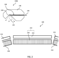
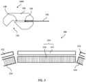
- FIGS. 2 and 3 are schematic illustrations of an example of one gamma-ray source assembly 130A and the associated PET detector ring 100.
- the gamma-ray source assembly 130A is located so that the gamma-ray source 130 is positioned over a gap between two PET detector blocks 214 in the PET detector ring assembly 100.
- the gamma-ray source assembly 130A comprises a gamma-ray source 130 and a radiation-shielding housing 136 for the gamma-ray source 130.
- the gamma-ray source assembly 130A is configured to hold the gamma-ray source 130 and be switched between an ON configuration and an OFF configuration.
- the remainder of the gamma photons from the gamma-ray source 130 are substantially absorbed by the housing 136.
- radiation absorption is never 100%.
- substantially absorbed refers to the gamma photons being strongly attenuated.
- the radiation-shielding housing 136 can be comprised of a radiation attenuating material such as tungsten.
- the gamma-ray source 130 is attached to an end of an articulating rod 134 that can manipulate the position of the gamma-ray source 130 within the housing 136 between the ON configuration and the OFF configuration.
- the radiation-shielding housing 136 can comprise a channel 138 and in the OFF configuration, the gamma-ray source 130 can be retracted into the channel 138 as shown in FIG. 3 so that the gamma photons emanating from the source is absorbed by the housing 136.
- the articulating rod 134 extends the gamma-ray source 130 out of the channel 138.
- the gamma-ray source 130 can be positioned in an opening 135 that is open toward the detector blocks 214.
- FIG. 4A is a flow chart 300 illustrating the method according to the invention for using one or more stationary gamma-ray sources 130 in a PET scanner as a transmission scan radiation source for generating scan data (list mode data) that can be used to generate attenuation maps is disclosed.
- the method comprises: (a) providing one or more stationary gamma-ray sources 130 in each of the PET detector ring assemblies 100 where the stationary gamma-ray sources are positioned outside the detector ring assembly 100, (box 310); (b) identifying forward scattered gamma-photons 12 which are gamma-photons that emanated from the stationary gamma-ray sources 130 that have forward scattered through a scintillator crystal in a first set of detector blocks 214 in a PET detector ring assembly, traversed through the FOV of the PET scanner, and are detected by a scintillator crystal in a second set of detector blocks in the PET detector ring assembly, via the PET scanner's coincidence electronics, (box 320); (c) acquiring list-mode data from a blank transmission scan (i.e.
- the PET scanner system 200 is configured to perform the method described in flowchart 300 is disclosed.
- the PET system comprises: a plurality of detector ring assemblies 100 comprising a plurality of scintillator crystals; a machine-readable storage medium 250; and a system controller connected to and in communication with said detector ring assemblies, wherein the machine-readable storage medium is encoded with a computer program code such that, when the computer program code is executed by the system controller 290, the system controller performs the method comprising: (a) providing one or more stationary gamma-ray sources in each of the PET detector ring assemblies where the stationary gamma-ray sources are positioned outside the detector ring assembly; (b) identifying forward scattered gamma-photons which are gamma-photons that emanated from the stationary gamma-ray sources that have forward scattered through a scintillator crystal in a first set of detector blocks in a PET detector ring assembly, traversed through the FOV of the PET scanner, and detected by a sci
- step (d) acquiring list-mode data from a transmission scan with a target body in the FOV; (e) simultaneously with step (d), acquiring list-mode data from a PET scan while the target body is in the FOV; (f) generating an attenuation map (a mu map) by comparing the list-mode data from the blank transmission scan against the list-mode data from the transmission scan with the target body in the FOV; and (g) applying the attenuation map to the list-mode data from the emission scan in step (e) to effect attenuation correction on the list-mode data from the emission scan.
- an attenuation map a mu map
- time-of-flight (TOF) consideration is applied to improve the quality of the transmission scan signal from the forward scattered gamma-photons.
- TOF time-of-flight
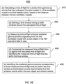
- applying TOF consideration to the transmission imaging scan using the stationary gamma-ray sources 130 comprises: (a) calculating a time-of-flight for scattered photons, which are photons from the gamma-ray sources that have undergone Compton scatter in the first scintillator crystal in the first detector block 214a, to reach a second scintillator crystal in the second detector block 214b, based on the distance between the two scintillator crystals. (See block 410).
- This step calculates what the TOF should be for a gamma-photon to travel from the first scintillator crystal to a second scintillator crystal on the opposing side across the FOV in a given PET scanner.
- the distance of interest here is the distance from the first detector block 214a (specifically a scintillator crystal associated with the first detector), in which the Compton scatter of the gamma photon occurs, to the second detector block 214b (specifically the scintillator crystal in the second detector) in which the coincidental scattered gamma-photon is detected.
- a time window is defined, where the time window has a width centered around the calculated TOF. (See block 420).
- the PET scanner system 200 is configured to perform the method described in flowchart 400 is disclosed.
- the PET system comprises: a plurality of detector ring assemblies 100 comprising a plurality of scintillator crystals; a machine-readable storage medium 250; and a system controller connected to and in communication with said detector ring assemblies, wherein the machine-readable storage medium is encoded with a computer program code such that, when the computer program code is executed by the system controller 290, the system controller performs the method comprising: (a) calculating a TOF for scattered photons, which are photons from the gamma-ray sources that have undergone Compton scatter in the first scintillator crystal in the first detector block, to reach a second scintillator crystal in the second detector block, based on the distance between the two scintillator crystals.
- This step calculates what the TOF should be for a gamma-photon to travel from the first scintillator crystal to a second scintillator crystal on the opposing side across the FOV in a given PET scanner.
- the distance of interest here is the distance from the first detector block (specifically a scintillator crystal associated with the first detector), in which the Compton scatter of the gamma photon occurs, to the second detector block (specifically the scintillator crystal in the second detector) in which the coincidental scattered gamma-photon is detected.
- a time window is defined, where the time window has a width centered around the calculated TOF.
- Cs-137 as the gamma-ray source, inventors experimentally confirmed that forward-scattered Cs-137 gamma rays provide improved transmission imaging in PET scanner compared to using the LSO background radiation by generating the transmission imaging data faster to generate attenuation ⁇ -map without the CT hardware.
- the experimental work is provided below.
- the disclosed invention was demonstrated using a 6-ring Biograph Vision PET/CT scanner with LSO scintillating and SiPM-based detectors.
- Each ring of the scanner comprised 38 detector blocks of size 64 mm by 32 mm, and each block contained 200 crystals of size 3.2 x 3.2 x 20 mm.
- Annihilation radiation in the measurement (511 keV) was created by a 23 MBq sealed 68 Ge source (germanium) in a thin steel tube.
- LM List-mode data
- Scan 1 was a 30-minute acquisition with no activity near the scanner, apart from the LSO background, and no objects in the FOV, not even the patient bed.
- Scan 2 was a 30-minute acquisition with the germanium source in location (A) near the scanner's transaxial center but at or just beyond the end of the axial range.
- Scan 3 was a 15-minute scan with the cesium source in position B, about 25 cm beyond the ring of detectors.
- Scan 5 was the same as scan 4 except that the patient bed was placed in the FOV to provide a simple phantom. Detected radiation corresponded to various physical phenomena, including: normal PET coincidences (the line DE in FIG.
- the measurements were made with unusual PET-scanner settings.
- the energy window was opened wide to accept events with an energy of 160 to 730 keV.
- the coincidence timing window was set to 6.64 ns, corresponding to a maximum chord length of about one meter. In normal PET imaging, both are restricted.
- the stationary Cs-137 sources 130 For transmission imaging, one would use the emitted photons from the stationary Cs-137 sources 130 efficiently and allow them to scatter from nearly all crystals in the PET detector ring 100 so that essentially all lines of response are sampled.
- the Cs-137 sources should be close to the PET detectors 214 but far enough away to maintain an acceptable singles rate.
- One way to do this is to distribute the stationary Cs-137 sources 130 in the PET detector ring 100 as shown in FIG. 1C . Since Biograph Vision PET scanner uses nineteen detector electronic assemblies 110, nineteen angular positions are shown in FIG. 1C . At each angle, two axial positions would be used, so the total number of sources should be 38.
- S bg-blank and S cs1-blank be the sinograms derived from scan 1 and scan 4, respectively. These were 3D sinograms but, in the analysis, it will be enough to treat them as 2D functions of radial and angular sinogram coordinates, summing all slices and all sinogram segments.
- a different source strength, As could be used in a new design, not 115 MBq as in the test described here.
- R is an operator that rotates the sinogram by one of the nineteen angles and the factor of 2 accounts for source placement in two axial positions. The rotation has to be performed carefully.
- the sinograms were converted from 180 to 360 degrees, then (1) was applied, then they were returned to the 180-degree representation.
- Cautions about using (1,2,3) are presented in Discussion section below.
- 2D energy histograms from scans 1, 2, 3, and 4 are shown in FIG. 6 .
- the energy range is 160 to 730 keV for each photon, as mentioned above.
- Prompt coincidences are shown in the bottom row and net-true coincidences (prompt minus delayed) in the top row.
- the middle row shows the net-true histograms with the LSO background subtracted, with a correction for the different scan times.
- the column representing scan 1 shows the expected energy spectra, including a spectrum of beta and gamma radiation in one detector and a 202 or 307-keV photopeak in the other one.
- the scan-2 column shows normal PET coincidences with several features of interest.
- the scan-3 column where one photon at a time was emitted from the cesium source, shows random coincidences in the bottom row but these disappear in the top row where delayed coincidences have been subtracted.
- These represent backscatter of 662-keV photons from the cesium source. Again, this signature of backscatter overlaps strongly with the LSO background.
- the scan-4 column shows the forward-scattered radiation on lines like GH in FIG. 5 .
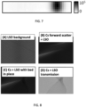
- FIG. 7 uses a grayscale representation to show the distribution of singles rates in the scanner's 228 detector blocks.
- the horizontal direction corresponds to the scanner's circumference and the vertical direction corresponds to the scanner's axial dimension.
- the maximum singles rate was about 1x10 5 counts/block in the area near the cesium source, compared to about 1x10 4 counts/block in areas where singles were mainly from LSO background radiation.
- the shape of the distribution confirmed that the source position was about 25 cm beyond the detectors.
- FIG. 8 shows the net-true sinograms from scans 1, 4, and 5 (parts A, B, C of the figure) and also the ratio of the scan-5 sinogram to the scan-4 sinogram (part D).
- the sinograms had 520 radial bins and 399 angular bins.
- the LSO-background sinogram from scan 1 was mainly featureless except for the expected pattern of high and low values at the edges of detector blocks, and the lower number of counts in the middle, due to solid-angle variations with position.
- the cesium spectrum from scan 4 featured a prominent diagonally-oriented feature due to forward-scattered radiation.
- the sinograms from scans 1 and 4 were rebinned from 520 radial bins by 399 angular bins to 52x19.
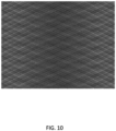
- a 38-source sinogram was estimated from (1) and is illustrated in FIG. 10 , which shows that its uniformity was similar to the sinogram from scan 1.
- the estimated 38-source sinogram had 19.6 times as many counts in the middle of the radial range and 23.2 times as many at the ends.
Landscapes
- Physics & Mathematics (AREA)
- Health & Medical Sciences (AREA)
- Engineering & Computer Science (AREA)
- Biomedical Technology (AREA)
- General Health & Medical Sciences (AREA)
- Medical Informatics (AREA)
- Nuclear Medicine, Radiotherapy & Molecular Imaging (AREA)
- Optics & Photonics (AREA)
- Life Sciences & Earth Sciences (AREA)
- General Physics & Mathematics (AREA)
- High Energy & Nuclear Physics (AREA)
- Molecular Biology (AREA)
- Spectroscopy & Molecular Physics (AREA)
- Nuclear Medicine (AREA)
- Measurement Of Radiation (AREA)
Claims (9)
- Positronenemissionstomographie-Abtastsystem (PET-Abtastsystem) (200), das Folgendes umfasst:eine Gantry (210);mehrere PET-Detektorringanordnungen (100), die in der Gantry (210) vorgesehen sind, wobei jede PET-Detektorringanordnung (100) mehrere Detektorelektronikanordnungen (110) umfasst, die in einer Ringkonfiguration um eine zentrale Öffnung angeordnet sind, wobei die mehreren PET-Detektorringanordnungen (100) entlang einer Längsachse, die durch die zentralen Öffnungen definiert ist, koaxial ausgerichtet sind;einen Patiententunnel (T), der sich durch die zentralen Öffnungen der koaxial ausgerichteten PET-Detektorringanordnungen (100) erstreckt, wobei die mehreren PET-Detektorringanordnungen (100) entlang einer Länge des Patiententunnels (T) koaxial ausgerichtet sind, wobei jede der mehreren Detektorelektronikanordnungen (110) einen Detektor (213) und einen oder mehrere Szintillationszählerkristalle (216), die dem Detektor (213) zugeordnet sind, umfasst; undeine oder mehrere ortsfeste Gamma-Strahlungsquellen (130), die in jeder der PET-Detektorringanordnungen (100) in der Gantry (210) vorgesehen sind, dadurch gekennzeichnet, dassdie eine oder die mehreren ortsfesten Gamma-Strahlungsquellen (130) in jeder der PET-Detektorringanordnungen (100) hinter der PET-Detektorringanordnung (100) vom Patiententunnel (T) entfernt und zwischen einem Paar der Detektorelektronikanordnungen (110) angeordnet sind.
- PET-Abtastsystem (200) nach Anspruch 1, wobei die ortsfesten Gamma-Strahlungsquellen (130) Cs-137, Kobalt-60 oder Natrium-22 sind.
- PET-Abtastsystem (200) nach Anspruch 1, wobei die ortsfesten Gamma-Strahlungsquellen (130) Cs-137 sind.
- PET-Abtastsystem (200) nach einem der Ansprüche 1-2, wobei jede der Gamma-Strahlungsquellen (130) in einer Anordnung (130A) vorgesehen ist, die Strahlungsabschirmung bereitstellt.
- PET-Abtastsystem (200) nach Anspruch 4 und einem der Ansprüche 2 und 3, wobei die Anordnung (130A), die die Strahlungsabschirmung bereitstellt, eine EIN-Konfiguration und eine AUS-Konfiguration umfasst, wobei dann, wenn sie sich in der EIN-Konfiguration befindet, im Gegensatz zu Gamma-Photonen vom Cs-137, die sich in der Richtung zu den Detektoranordnungen bewegen, Reste der Gamma-Photonen vom Cs-137 im Wesentlichen durch die Anordnung (130A), die die Strahlungsabschirmung bereitstellt, absorbiert werden.
- PET-Abtastsystem (200) nach Anspruch 5, wobei die Anordnung (130A), die Strahlungsabschirmung bereitstellt, zumindest teilweise aus Wolfram besteht.
- PET-Abtastsystem (200) nach Anspruch 1, wobei die PET-Abtasteinrichtung eine PET/MR-Abtasteinrichtung ist.
- PET-Abtastsystem (200) nach Anspruch 1, wobei die PET-Abtasteinrichtung eine PET/CT-Abtasteinrichtung ist.
- Verfahren zum Verwenden einer oder mehrerer ortsfester Gamma-Strahlungsquellen (130), die in einer PET-Abtasteinrichtung vorgesehen sind, als Durchgangsabtastungs-Strahlungsquelle zum Erzeugen von Abtastdaten, die verwendet werden können, um Dämpfungsabbildungen zu erzeugen, wobei die PET-Abtasteinrichtung (200) mehrere PET-Detektorringanordnungen (100) umfasst, wobei das Verfahren Folgendes umfasst:(a) Bereitstellen (310) der einen oder der mehreren ortsfesten Gamma-Strahlungsquellen (130) in jeder der PET-Detektorringanordnungen (100), wobei die ortsfesten Gamma-Strahlungsquellen (130) hinter der Detektorringanordnung (100) vom Patiententunnel (T) entfernt und zwischen einem Paar der Detektorelektronikanordnungen (110) angeordnet sind;(b) Identifizieren (320) nach vorne gestreuter Gamma-Photonen 12, die Gamma-Photonen sind, die von den ortsfesten Gamma-Strahlungsquellen (130) ausgestrahlt wurden, die durch einen Szintillationszählerkristall in einer ersten Gruppe von Detektorblöcken (214) in einer PET-Detektorringanordnung (100) nach vorne gestreut worden sind, das Blickfeld (FOV) der PET-Abtasteinrichtung durchlaufen haben und durch einen Szintillationszählerkristall in einer zweiten Gruppe von Detektorblöcken in der PET-Detektorringanordnung (100) detektiert worden sind, über die Koinzidenzelektronik der PET-Abtasteinrichtung;(c) Erfassen (330) von Listendaten von einer leeren Durchgangsabtastung ohne Aktivität im FOV;(d) Erfassen (340) von Listendaten von einer Durchgangsabtastung mit einem Zielkörper im FOV,wobei es ferner gleichzeitig mit Schritt (d) das Erfassen von Listendaten von einer PET-Abtastung, während sich der Zielkörper im FOV befindet, umfasst;(e) Erzeugen (360) einer Dämpfungsabbildung durch Vergleichen der Listendaten von der leeren Durchgangsabtastung mit den Listendaten von der Durchgangsabtastung mit dem Zielkörper im FOV; und(f) Anwenden (370) der Dämpfungsabbildung auf die Listendaten von der PET-Abtastung, um eine Dämpfungskorrektur auf den Listendaten von der PET-Abtastung durchzuführen.
Priority Applications (1)
| Application Number | Priority Date | Filing Date | Title |
|---|---|---|---|
| EP25169800.7A EP4560359A3 (de) | 2020-05-01 | 2021-04-20 | Transmissionsabbildung in einem pet-scanner auf der basis von vorwärtsgestreuten gammastrahlungen mit koinzidenzdetektion |
Applications Claiming Priority (2)
| Application Number | Priority Date | Filing Date | Title |
|---|---|---|---|
| US202063018654P | 2020-05-01 | 2020-05-01 | |
| PCT/US2021/070429 WO2021222921A1 (en) | 2020-05-01 | 2021-04-20 | Transmission imaging in a pet scanner based on forward-scattered gamma rays with coincidence detection |
Related Child Applications (2)
| Application Number | Title | Priority Date | Filing Date |
|---|---|---|---|
| EP25169800.7A Division-Into EP4560359A3 (de) | 2020-05-01 | 2021-04-20 | Transmissionsabbildung in einem pet-scanner auf der basis von vorwärtsgestreuten gammastrahlungen mit koinzidenzdetektion |
| EP25169800.7A Division EP4560359A3 (de) | 2020-05-01 | 2021-04-20 | Transmissionsabbildung in einem pet-scanner auf der basis von vorwärtsgestreuten gammastrahlungen mit koinzidenzdetektion |
Publications (3)
| Publication Number | Publication Date |
|---|---|
| EP4127777A1 EP4127777A1 (de) | 2023-02-08 |
| EP4127777C0 EP4127777C0 (de) | 2025-07-02 |
| EP4127777B1 true EP4127777B1 (de) | 2025-07-02 |
Family
ID=75905081
Family Applications (2)
| Application Number | Title | Priority Date | Filing Date |
|---|---|---|---|
| EP25169800.7A Pending EP4560359A3 (de) | 2020-05-01 | 2021-04-20 | Transmissionsabbildung in einem pet-scanner auf der basis von vorwärtsgestreuten gammastrahlungen mit koinzidenzdetektion |
| EP21725364.0A Active EP4127777B1 (de) | 2020-05-01 | 2021-04-20 | Transmissionsabbildung in einem pet-scanner auf der basis von vorwärtsgestreuten gammastrahlungen mit koinzidenzdetektion |
Family Applications Before (1)
| Application Number | Title | Priority Date | Filing Date |
|---|---|---|---|
| EP25169800.7A Pending EP4560359A3 (de) | 2020-05-01 | 2021-04-20 | Transmissionsabbildung in einem pet-scanner auf der basis von vorwärtsgestreuten gammastrahlungen mit koinzidenzdetektion |
Country Status (5)
| Country | Link |
|---|---|
| US (1) | US11768300B2 (de) |
| EP (2) | EP4560359A3 (de) |
| JP (1) | JP7676443B2 (de) |
| CN (1) | CN115485585B (de) |
| WO (1) | WO2021222921A1 (de) |
Families Citing this family (2)
| Publication number | Priority date | Publication date | Assignee | Title |
|---|---|---|---|---|
| US12013450B2 (en) | 2022-04-20 | 2024-06-18 | Siemens Medical Solutions Usa, Inc. | PET transmission source based on continuous bed motion |
| JP2024033150A (ja) * | 2022-08-30 | 2024-03-13 | 浜松ホトニクス株式会社 | 画像取得装置および画像取得方法 |
Family Cites Families (22)
| Publication number | Priority date | Publication date | Assignee | Title |
|---|---|---|---|---|
| JPS586499A (ja) * | 1981-07-06 | 1983-01-14 | 工業技術院長 | ポジトロンct装置校正用線源 |
| CA2077735A1 (en) * | 1992-09-08 | 1994-03-09 | Roger Lecomte | Over-sampling pet tomograph operating in stationary mode |
| US6718006B2 (en) * | 1998-05-01 | 2004-04-06 | Cti Pet Systems, Inc. | Fiber-optic encoding for dual transmission measurements in positron emission tomography |
| JP4333692B2 (ja) * | 2002-03-20 | 2009-09-16 | 株式会社日立製作所 | 放射線検査装置 |
| JP4507916B2 (ja) * | 2004-04-02 | 2010-07-21 | 株式会社島津製作所 | 医用画像診断装置 |
| JP4857724B2 (ja) * | 2005-11-17 | 2012-01-18 | 株式会社日立製作所 | 核医学診断装置 |
| US7791030B2 (en) * | 2006-09-19 | 2010-09-07 | Shimadzu Corporation | Nuclear medical diagnostic device |
| JP5262152B2 (ja) * | 2008-02-06 | 2013-08-14 | 株式会社島津製作所 | 診断システム |
| US8406495B2 (en) * | 2008-09-17 | 2013-03-26 | Koninklijke Philips Electronics N.V. | MR segmentation using transmission data in hybrid nuclear/MR imaging |
| JP2009058528A (ja) * | 2008-12-01 | 2009-03-19 | Hitachi Ltd | 放射線検査装置 |
| EP2360493A1 (de) * | 2010-02-15 | 2011-08-24 | Bergen Teknologioverføring AS | Detektoranordnung für eine tomografische Bildgebungsvorrichtung, insbesondere für einen Positronemissionstomografen |
| CN102906595B (zh) * | 2010-05-18 | 2014-12-31 | 株式会社岛津制作所 | 正电子ct装置和定时校正方法 |
| JP6067959B2 (ja) * | 2010-06-17 | 2017-01-25 | 東芝メディカルシステムズ株式会社 | 核医学イメージング装置および方法 |
| JP5526435B2 (ja) * | 2011-08-03 | 2014-06-18 | 独立行政法人理化学研究所 | Pet装置およびそのイメージング方法 |
| US8866086B2 (en) * | 2011-08-05 | 2014-10-21 | Siemens Medical Solutions Usa, Inc. | PET scanner with emission and transmission structures in a checkerboard configuration |
| US20140217294A1 (en) * | 2013-02-05 | 2014-08-07 | Siemens Medical Solutions Usa, Inc. | Method for Using LSO Background Radiation as a Transmission Source Using Time of Flight Information |
| CN104173074B (zh) * | 2014-07-21 | 2016-07-06 | 北京永新医疗设备有限公司 | 单光子发射断层成像系统的几何刻度方法 |
| US9801597B2 (en) * | 2014-09-24 | 2017-10-31 | General Electric Company | Multi-detector imaging system with x-ray detection |
| EP3332269B1 (de) * | 2015-08-07 | 2020-09-09 | Koninklijke Philips N.V. | Hybrider pet-/ct-bildgebungsdetektor |
| JP6827316B2 (ja) * | 2016-12-22 | 2021-02-10 | 浜松ホトニクス株式会社 | 放射線位置検出方法、放射線位置検出器及びpet装置 |
| CN111068186B (zh) * | 2018-10-22 | 2021-03-02 | 清华大学 | Ct成像和图像引导放射治疗装置 |
| FI3825736T3 (fi) * | 2019-11-22 | 2025-10-02 | Hellma Mat Gmbh | Yksi- ja kaksisuuntaisia comptonin sirontaprosesseja käyttävä kuvantamisilmaisinjärjestelmä gammasäteilyyn |
-
2021
- 2021-04-20 EP EP25169800.7A patent/EP4560359A3/de active Pending
- 2021-04-20 CN CN202180032057.8A patent/CN115485585B/zh active Active
- 2021-04-20 JP JP2022566314A patent/JP7676443B2/ja active Active
- 2021-04-20 EP EP21725364.0A patent/EP4127777B1/de active Active
- 2021-04-20 US US17/756,910 patent/US11768300B2/en active Active
- 2021-04-20 WO PCT/US2021/070429 patent/WO2021222921A1/en not_active Ceased
Also Published As
| Publication number | Publication date |
|---|---|
| EP4127777A1 (de) | 2023-02-08 |
| EP4127777C0 (de) | 2025-07-02 |
| WO2021222921A1 (en) | 2021-11-04 |
| CN115485585A (zh) | 2022-12-16 |
| JP2023524060A (ja) | 2023-06-08 |
| EP4560359A3 (de) | 2025-07-16 |
| US20230003909A1 (en) | 2023-01-05 |
| EP4560359A2 (de) | 2025-05-28 |
| CN115485585B (zh) | 2026-04-17 |
| US11768300B2 (en) | 2023-09-26 |
| JP7676443B2 (ja) | 2025-05-14 |
Similar Documents
| Publication | Publication Date | Title |
|---|---|---|
| Madsen et al. | AAPM task group 108: PET and PET/CT shielding requirements | |
| Cho et al. | Circular ring transverse axial positron camera for 3-dimensional reconstruction of radionuclides distribution | |
| Knoll | Single-photon emission computed tomography | |
| CN109313276B (zh) | 伽马射线图像获取装置及伽马射线图像获取方法 | |
| Livieratos | Basic principles of SPECT and PET imaging | |
| Ljungberg | Absolute quantitation of SPECT studies | |
| Martin et al. | Quantitative PET with positron emitters that emit prompt gamma rays | |
| US11768300B2 (en) | Transmission imaging in a pet scanner based on forward-scattered gamma rays with coincidence detection | |
| US6803580B2 (en) | Pet and spect systems with attenuation correction | |
| İnce et al. | Collimator and energy window optimization for YTTRIUM-90 bremsstrahlung SPECT imaging | |
| JP4976874B2 (ja) | 核医学診断装置 | |
| EP0846275A1 (de) | Abbildungsvorrichtung | |
| Grimes | Patient-specific internal dose calculation techniques for clinical use in targeted radionuclide therapy | |
| Hamill et al. | Transmission Imaging in a PET Scanner Based on Forward-Scattered 662-keV Photons | |
| Lecoq | Detectors in Medicine and Biology | |
| Khalil | Positron emission tomography (PET): Basic principles | |
| Abushab | Simulation and image reconstruction of clinical TOF-PET scanners | |
| Kaalep | Standardisation and harmonisation of quantitative oncology PET/CT studies | |
| Saha | Data Acquisition and Corrections | |
| Palmieri et al. | Principles in Conventional PET/CT | |
| Olshanoski | Monte Carlo Simulation and Experimentation of Non-Collinear Gamma Ray Correlations as a Novel Medical Imaging Modality | |
| Sharp et al. | Positron emission tomography | |
| Pourmoghaddas | Quantitative Imaging With a Pinhole Cardiac SPECT CZT Camera | |
| Moore et al. | PET and PET/CT physics, instrumentation, and artifacts | |
| Ishihara | Investigation of accuracy in quantitation of 18F-FDG concentration of PET/CT |
Legal Events
| Date | Code | Title | Description |
|---|---|---|---|
| STAA | Information on the status of an ep patent application or granted ep patent |
Free format text: STATUS: UNKNOWN |
|
| STAA | Information on the status of an ep patent application or granted ep patent |
Free format text: STATUS: THE INTERNATIONAL PUBLICATION HAS BEEN MADE |
|
| PUAI | Public reference made under article 153(3) epc to a published international application that has entered the european phase |
Free format text: ORIGINAL CODE: 0009012 |
|
| STAA | Information on the status of an ep patent application or granted ep patent |
Free format text: STATUS: REQUEST FOR EXAMINATION WAS MADE |
|
| 17P | Request for examination filed |
Effective date: 20221102 |
|
| AK | Designated contracting states |
Kind code of ref document: A1 Designated state(s): AL AT BE BG CH CY CZ DE DK EE ES FI FR GB GR HR HU IE IS IT LI LT LU LV MC MK MT NL NO PL PT RO RS SE SI SK SM TR |
|
| DAV | Request for validation of the european patent (deleted) | ||
| DAX | Request for extension of the european patent (deleted) | ||
| GRAP | Despatch of communication of intention to grant a patent |
Free format text: ORIGINAL CODE: EPIDOSNIGR1 |
|
| STAA | Information on the status of an ep patent application or granted ep patent |
Free format text: STATUS: GRANT OF PATENT IS INTENDED |
|
| INTG | Intention to grant announced |
Effective date: 20250205 |
|
| GRAS | Grant fee paid |
Free format text: ORIGINAL CODE: EPIDOSNIGR3 |
|
| GRAA | (expected) grant |
Free format text: ORIGINAL CODE: 0009210 |
|
| STAA | Information on the status of an ep patent application or granted ep patent |
Free format text: STATUS: THE PATENT HAS BEEN GRANTED |
|
| AK | Designated contracting states |
Kind code of ref document: B1 Designated state(s): AL AT BE BG CH CY CZ DE DK EE ES FI FR GB GR HR HU IE IS IT LI LT LU LV MC MK MT NL NO PL PT RO RS SE SI SK SM TR |
|
| REG | Reference to a national code |
Ref country code: GB Ref legal event code: FG4D |
|
| REG | Reference to a national code |
Ref country code: CH Ref legal event code: EP |
|
| REG | Reference to a national code |
Ref country code: DE Ref legal event code: R096 Ref document number: 602021033333 Country of ref document: DE |
|
| REG | Reference to a national code |
Ref country code: IE Ref legal event code: FG4D |
|
| U01 | Request for unitary effect filed |
Effective date: 20250717 |
|
| U07 | Unitary effect registered |
Designated state(s): AT BE BG DE DK EE FI FR IT LT LU LV MT NL PT RO SE SI Effective date: 20250724 |
|
| PG25 | Lapsed in a contracting state [announced via postgrant information from national office to epo] |
Ref country code: IS Free format text: LAPSE BECAUSE OF FAILURE TO SUBMIT A TRANSLATION OF THE DESCRIPTION OR TO PAY THE FEE WITHIN THE PRESCRIBED TIME-LIMIT Effective date: 20251102 |
|
| PG25 | Lapsed in a contracting state [announced via postgrant information from national office to epo] |
Ref country code: NO Free format text: LAPSE BECAUSE OF FAILURE TO SUBMIT A TRANSLATION OF THE DESCRIPTION OR TO PAY THE FEE WITHIN THE PRESCRIBED TIME-LIMIT Effective date: 20251002 |
|
| PG25 | Lapsed in a contracting state [announced via postgrant information from national office to epo] |
Ref country code: HR Free format text: LAPSE BECAUSE OF FAILURE TO SUBMIT A TRANSLATION OF THE DESCRIPTION OR TO PAY THE FEE WITHIN THE PRESCRIBED TIME-LIMIT Effective date: 20250702 |
|
| PG25 | Lapsed in a contracting state [announced via postgrant information from national office to epo] |
Ref country code: GR Free format text: LAPSE BECAUSE OF FAILURE TO SUBMIT A TRANSLATION OF THE DESCRIPTION OR TO PAY THE FEE WITHIN THE PRESCRIBED TIME-LIMIT Effective date: 20251003 |
|
| PG25 | Lapsed in a contracting state [announced via postgrant information from national office to epo] |
Ref country code: CZ Free format text: LAPSE BECAUSE OF FAILURE TO SUBMIT A TRANSLATION OF THE DESCRIPTION OR TO PAY THE FEE WITHIN THE PRESCRIBED TIME-LIMIT Effective date: 20250702 |
|
| PG25 | Lapsed in a contracting state [announced via postgrant information from national office to epo] |
Ref country code: PL Free format text: LAPSE BECAUSE OF FAILURE TO SUBMIT A TRANSLATION OF THE DESCRIPTION OR TO PAY THE FEE WITHIN THE PRESCRIBED TIME-LIMIT Effective date: 20250702 |
|
| PG25 | Lapsed in a contracting state [announced via postgrant information from national office to epo] |
Ref country code: RS Free format text: LAPSE BECAUSE OF FAILURE TO SUBMIT A TRANSLATION OF THE DESCRIPTION OR TO PAY THE FEE WITHIN THE PRESCRIBED TIME-LIMIT Effective date: 20251002 |
|
| PG25 | Lapsed in a contracting state [announced via postgrant information from national office to epo] |
Ref country code: ES Free format text: LAPSE BECAUSE OF FAILURE TO SUBMIT A TRANSLATION OF THE DESCRIPTION OR TO PAY THE FEE WITHIN THE PRESCRIBED TIME-LIMIT Effective date: 20250702 |
|
| PG25 | Lapsed in a contracting state [announced via postgrant information from national office to epo] |
Ref country code: SM Free format text: LAPSE BECAUSE OF FAILURE TO SUBMIT A TRANSLATION OF THE DESCRIPTION OR TO PAY THE FEE WITHIN THE PRESCRIBED TIME-LIMIT Effective date: 20250702 |
|
| PG25 | Lapsed in a contracting state [announced via postgrant information from national office to epo] |
Ref country code: SK Free format text: LAPSE BECAUSE OF FAILURE TO SUBMIT A TRANSLATION OF THE DESCRIPTION OR TO PAY THE FEE WITHIN THE PRESCRIBED TIME-LIMIT Effective date: 20250702 |
|
| PLBE | No opposition filed within time limit |
Free format text: ORIGINAL CODE: 0009261 |
|
| STAA | Information on the status of an ep patent application or granted ep patent |
Free format text: STATUS: NO OPPOSITION FILED WITHIN TIME LIMIT |