EP4127615B1 - Speicherbehälter für flüssigen wasserstoff mit füllstandsanzeige - Google Patents
Speicherbehälter für flüssigen wasserstoff mit füllstandsanzeige Download PDFInfo
- Publication number
- EP4127615B1 EP4127615B1 EP21716595.0A EP21716595A EP4127615B1 EP 4127615 B1 EP4127615 B1 EP 4127615B1 EP 21716595 A EP21716595 A EP 21716595A EP 4127615 B1 EP4127615 B1 EP 4127615B1
- Authority
- EP
- European Patent Office
- Prior art keywords
- cell
- gas
- liquid hydrogen
- storage tank
- heating element
- Prior art date
- Legal status (The legal status is an assumption and is not a legal conclusion. Google has not performed a legal analysis and makes no representation as to the accuracy of the status listed.)
- Active
Links
Images



Classifications
-
- F—MECHANICAL ENGINEERING; LIGHTING; HEATING; WEAPONS; BLASTING
- F17—STORING OR DISTRIBUTING GASES OR LIQUIDS
- F17C—VESSELS FOR CONTAINING OR STORING COMPRESSED, LIQUEFIED OR SOLIDIFIED GASES; FIXED-CAPACITY GAS-HOLDERS; FILLING VESSELS WITH, OR DISCHARGING FROM VESSELS, COMPRESSED, LIQUEFIED, OR SOLIDIFIED GASES
- F17C13/00—Details of vessels or of the filling or discharging of vessels
- F17C13/02—Special adaptations of indicating, measuring, or monitoring equipment
- F17C13/025—Special adaptations of indicating, measuring, or monitoring equipment having the pressure as the parameter
-
- F—MECHANICAL ENGINEERING; LIGHTING; HEATING; WEAPONS; BLASTING
- F17—STORING OR DISTRIBUTING GASES OR LIQUIDS
- F17C—VESSELS FOR CONTAINING OR STORING COMPRESSED, LIQUEFIED OR SOLIDIFIED GASES; FIXED-CAPACITY GAS-HOLDERS; FILLING VESSELS WITH, OR DISCHARGING FROM VESSELS, COMPRESSED, LIQUEFIED, OR SOLIDIFIED GASES
- F17C13/00—Details of vessels or of the filling or discharging of vessels
- F17C13/02—Special adaptations of indicating, measuring, or monitoring equipment
- F17C13/021—Special adaptations of indicating, measuring, or monitoring equipment having the height as the parameter
-
- G—PHYSICS
- G01—MEASURING; TESTING
- G01F—MEASURING VOLUME, VOLUME FLOW, MASS FLOW OR LIQUID LEVEL; METERING BY VOLUME
- G01F23/00—Indicating or measuring liquid level or level of fluent solid material, e.g. indicating in terms of volume or indicating by means of an alarm
- G01F23/14—Indicating or measuring liquid level or level of fluent solid material, e.g. indicating in terms of volume or indicating by means of an alarm by measurement of pressure
- G01F23/16—Indicating, recording, or alarm devices being actuated by mechanical or fluid means, e.g. using gas, mercury, or a diaphragm as transmitting element, or by a column of liquid
-
- F—MECHANICAL ENGINEERING; LIGHTING; HEATING; WEAPONS; BLASTING
- F17—STORING OR DISTRIBUTING GASES OR LIQUIDS
- F17C—VESSELS FOR CONTAINING OR STORING COMPRESSED, LIQUEFIED OR SOLIDIFIED GASES; FIXED-CAPACITY GAS-HOLDERS; FILLING VESSELS WITH, OR DISCHARGING FROM VESSELS, COMPRESSED, LIQUEFIED, OR SOLIDIFIED GASES
- F17C13/00—Details of vessels or of the filling or discharging of vessels
- F17C13/08—Mounting arrangements for vessels
- F17C13/082—Mounting arrangements for vessels for large sea-borne storage vessels
-
- G—PHYSICS
- G01—MEASURING; TESTING
- G01F—MEASURING VOLUME, VOLUME FLOW, MASS FLOW OR LIQUID LEVEL; METERING BY VOLUME
- G01F23/00—Indicating or measuring liquid level or level of fluent solid material, e.g. indicating in terms of volume or indicating by means of an alarm
- G01F23/22—Indicating or measuring liquid level or level of fluent solid material, e.g. indicating in terms of volume or indicating by means of an alarm by measuring physical variables, other than linear dimensions, pressure or weight, dependent on the level to be measured, e.g. by difference of heat transfer of steam or water
-
- F—MECHANICAL ENGINEERING; LIGHTING; HEATING; WEAPONS; BLASTING
- F17—STORING OR DISTRIBUTING GASES OR LIQUIDS
- F17C—VESSELS FOR CONTAINING OR STORING COMPRESSED, LIQUEFIED OR SOLIDIFIED GASES; FIXED-CAPACITY GAS-HOLDERS; FILLING VESSELS WITH, OR DISCHARGING FROM VESSELS, COMPRESSED, LIQUEFIED, OR SOLIDIFIED GASES
- F17C2201/00—Vessel construction, in particular geometry, arrangement or size
- F17C2201/01—Shape
- F17C2201/0104—Shape cylindrical
- F17C2201/0109—Shape cylindrical with exteriorly curved end-piece
-
- F—MECHANICAL ENGINEERING; LIGHTING; HEATING; WEAPONS; BLASTING
- F17—STORING OR DISTRIBUTING GASES OR LIQUIDS
- F17C—VESSELS FOR CONTAINING OR STORING COMPRESSED, LIQUEFIED OR SOLIDIFIED GASES; FIXED-CAPACITY GAS-HOLDERS; FILLING VESSELS WITH, OR DISCHARGING FROM VESSELS, COMPRESSED, LIQUEFIED, OR SOLIDIFIED GASES
- F17C2201/00—Vessel construction, in particular geometry, arrangement or size
- F17C2201/03—Orientation
- F17C2201/032—Orientation with substantially vertical main axis
-
- F—MECHANICAL ENGINEERING; LIGHTING; HEATING; WEAPONS; BLASTING
- F17—STORING OR DISTRIBUTING GASES OR LIQUIDS
- F17C—VESSELS FOR CONTAINING OR STORING COMPRESSED, LIQUEFIED OR SOLIDIFIED GASES; FIXED-CAPACITY GAS-HOLDERS; FILLING VESSELS WITH, OR DISCHARGING FROM VESSELS, COMPRESSED, LIQUEFIED, OR SOLIDIFIED GASES
- F17C2201/00—Vessel construction, in particular geometry, arrangement or size
- F17C2201/05—Size
- F17C2201/054—Size medium (>1 m3)
-
- F—MECHANICAL ENGINEERING; LIGHTING; HEATING; WEAPONS; BLASTING
- F17—STORING OR DISTRIBUTING GASES OR LIQUIDS
- F17C—VESSELS FOR CONTAINING OR STORING COMPRESSED, LIQUEFIED OR SOLIDIFIED GASES; FIXED-CAPACITY GAS-HOLDERS; FILLING VESSELS WITH, OR DISCHARGING FROM VESSELS, COMPRESSED, LIQUEFIED, OR SOLIDIFIED GASES
- F17C2203/00—Vessel construction, in particular walls or details thereof
- F17C2203/03—Thermal insulations
- F17C2203/0304—Thermal insulations by solid means
- F17C2203/0308—Radiation shield
- F17C2203/032—Multi-sheet layers
-
- F—MECHANICAL ENGINEERING; LIGHTING; HEATING; WEAPONS; BLASTING
- F17—STORING OR DISTRIBUTING GASES OR LIQUIDS
- F17C—VESSELS FOR CONTAINING OR STORING COMPRESSED, LIQUEFIED OR SOLIDIFIED GASES; FIXED-CAPACITY GAS-HOLDERS; FILLING VESSELS WITH, OR DISCHARGING FROM VESSELS, COMPRESSED, LIQUEFIED, OR SOLIDIFIED GASES
- F17C2203/00—Vessel construction, in particular walls or details thereof
- F17C2203/06—Materials for walls or layers thereof; Properties or structures of walls or their materials
- F17C2203/0602—Wall structures; Special features thereof
- F17C2203/0612—Wall structures
- F17C2203/0626—Multiple walls
- F17C2203/0629—Two walls
-
- F—MECHANICAL ENGINEERING; LIGHTING; HEATING; WEAPONS; BLASTING
- F17—STORING OR DISTRIBUTING GASES OR LIQUIDS
- F17C—VESSELS FOR CONTAINING OR STORING COMPRESSED, LIQUEFIED OR SOLIDIFIED GASES; FIXED-CAPACITY GAS-HOLDERS; FILLING VESSELS WITH, OR DISCHARGING FROM VESSELS, COMPRESSED, LIQUEFIED, OR SOLIDIFIED GASES
- F17C2221/00—Handled fluid, in particular type of fluid
- F17C2221/01—Pure fluids
- F17C2221/012—Hydrogen
-
- F—MECHANICAL ENGINEERING; LIGHTING; HEATING; WEAPONS; BLASTING
- F17—STORING OR DISTRIBUTING GASES OR LIQUIDS
- F17C—VESSELS FOR CONTAINING OR STORING COMPRESSED, LIQUEFIED OR SOLIDIFIED GASES; FIXED-CAPACITY GAS-HOLDERS; FILLING VESSELS WITH, OR DISCHARGING FROM VESSELS, COMPRESSED, LIQUEFIED, OR SOLIDIFIED GASES
- F17C2223/00—Handled fluid before transfer, i.e. state of fluid when stored in the vessel or before transfer from the vessel
- F17C2223/01—Handled fluid before transfer, i.e. state of fluid when stored in the vessel or before transfer from the vessel characterised by the phase
- F17C2223/0146—Two-phase
- F17C2223/0153—Liquefied gas, e.g. LPG, GPL
- F17C2223/0161—Liquefied gas, e.g. LPG, GPL cryogenic, e.g. LNG, GNL, PLNG
-
- F—MECHANICAL ENGINEERING; LIGHTING; HEATING; WEAPONS; BLASTING
- F17—STORING OR DISTRIBUTING GASES OR LIQUIDS
- F17C—VESSELS FOR CONTAINING OR STORING COMPRESSED, LIQUEFIED OR SOLIDIFIED GASES; FIXED-CAPACITY GAS-HOLDERS; FILLING VESSELS WITH, OR DISCHARGING FROM VESSELS, COMPRESSED, LIQUEFIED, OR SOLIDIFIED GASES
- F17C2223/00—Handled fluid before transfer, i.e. state of fluid when stored in the vessel or before transfer from the vessel
- F17C2223/03—Handled fluid before transfer, i.e. state of fluid when stored in the vessel or before transfer from the vessel characterised by the pressure level
- F17C2223/033—Small pressure, e.g. for liquefied gas
-
- F—MECHANICAL ENGINEERING; LIGHTING; HEATING; WEAPONS; BLASTING
- F17—STORING OR DISTRIBUTING GASES OR LIQUIDS
- F17C—VESSELS FOR CONTAINING OR STORING COMPRESSED, LIQUEFIED OR SOLIDIFIED GASES; FIXED-CAPACITY GAS-HOLDERS; FILLING VESSELS WITH, OR DISCHARGING FROM VESSELS, COMPRESSED, LIQUEFIED, OR SOLIDIFIED GASES
- F17C2250/00—Accessories; Control means; Indicating, measuring or monitoring of parameters
- F17C2250/04—Indicating or measuring of parameters as input values
- F17C2250/0404—Parameters indicated or measured
- F17C2250/0408—Level of content in the vessel
-
- F—MECHANICAL ENGINEERING; LIGHTING; HEATING; WEAPONS; BLASTING
- F17—STORING OR DISTRIBUTING GASES OR LIQUIDS
- F17C—VESSELS FOR CONTAINING OR STORING COMPRESSED, LIQUEFIED OR SOLIDIFIED GASES; FIXED-CAPACITY GAS-HOLDERS; FILLING VESSELS WITH, OR DISCHARGING FROM VESSELS, COMPRESSED, LIQUEFIED, OR SOLIDIFIED GASES
- F17C2250/00—Accessories; Control means; Indicating, measuring or monitoring of parameters
- F17C2250/04—Indicating or measuring of parameters as input values
- F17C2250/0404—Parameters indicated or measured
- F17C2250/0408—Level of content in the vessel
- F17C2250/0417—Level of content in the vessel with electrical means
-
- F—MECHANICAL ENGINEERING; LIGHTING; HEATING; WEAPONS; BLASTING
- F17—STORING OR DISTRIBUTING GASES OR LIQUIDS
- F17C—VESSELS FOR CONTAINING OR STORING COMPRESSED, LIQUEFIED OR SOLIDIFIED GASES; FIXED-CAPACITY GAS-HOLDERS; FILLING VESSELS WITH, OR DISCHARGING FROM VESSELS, COMPRESSED, LIQUEFIED, OR SOLIDIFIED GASES
- F17C2250/00—Accessories; Control means; Indicating, measuring or monitoring of parameters
- F17C2250/04—Indicating or measuring of parameters as input values
- F17C2250/0486—Indicating or measuring characterised by the location
- F17C2250/0491—Parameters measured at or inside the vessel
-
- F—MECHANICAL ENGINEERING; LIGHTING; HEATING; WEAPONS; BLASTING
- F17—STORING OR DISTRIBUTING GASES OR LIQUIDS
- F17C—VESSELS FOR CONTAINING OR STORING COMPRESSED, LIQUEFIED OR SOLIDIFIED GASES; FIXED-CAPACITY GAS-HOLDERS; FILLING VESSELS WITH, OR DISCHARGING FROM VESSELS, COMPRESSED, LIQUEFIED, OR SOLIDIFIED GASES
- F17C2250/00—Accessories; Control means; Indicating, measuring or monitoring of parameters
- F17C2250/07—Actions triggered by measured parameters
- F17C2250/072—Action when predefined value is reached
- F17C2250/075—Action when predefined value is reached when full
-
- F—MECHANICAL ENGINEERING; LIGHTING; HEATING; WEAPONS; BLASTING
- F17—STORING OR DISTRIBUTING GASES OR LIQUIDS
- F17C—VESSELS FOR CONTAINING OR STORING COMPRESSED, LIQUEFIED OR SOLIDIFIED GASES; FIXED-CAPACITY GAS-HOLDERS; FILLING VESSELS WITH, OR DISCHARGING FROM VESSELS, COMPRESSED, LIQUEFIED, OR SOLIDIFIED GASES
- F17C2265/00—Effects achieved by gas storage or gas handling
- F17C2265/06—Fluid distribution
- F17C2265/065—Fluid distribution for refuelling vehicle fuel tanks
-
- F—MECHANICAL ENGINEERING; LIGHTING; HEATING; WEAPONS; BLASTING
- F17—STORING OR DISTRIBUTING GASES OR LIQUIDS
- F17C—VESSELS FOR CONTAINING OR STORING COMPRESSED, LIQUEFIED OR SOLIDIFIED GASES; FIXED-CAPACITY GAS-HOLDERS; FILLING VESSELS WITH, OR DISCHARGING FROM VESSELS, COMPRESSED, LIQUEFIED, OR SOLIDIFIED GASES
- F17C2270/00—Applications
- F17C2270/01—Applications for fluid transport or storage
- F17C2270/0102—Applications for fluid transport or storage on or in the water
- F17C2270/0105—Ships
-
- Y—GENERAL TAGGING OF NEW TECHNOLOGICAL DEVELOPMENTS; GENERAL TAGGING OF CROSS-SECTIONAL TECHNOLOGIES SPANNING OVER SEVERAL SECTIONS OF THE IPC; TECHNICAL SUBJECTS COVERED BY FORMER USPC CROSS-REFERENCE ART COLLECTIONS [XRACs] AND DIGESTS
- Y02—TECHNOLOGIES OR APPLICATIONS FOR MITIGATION OR ADAPTATION AGAINST CLIMATE CHANGE
- Y02E—REDUCTION OF GREENHOUSE GAS [GHG] EMISSIONS, RELATED TO ENERGY GENERATION, TRANSMISSION OR DISTRIBUTION
- Y02E60/00—Enabling technologies; Technologies with a potential or indirect contribution to GHG emissions mitigation
- Y02E60/30—Hydrogen technology
- Y02E60/32—Hydrogen storage
Definitions
- the invention relates to a storage container for liquid hydrogen, comprising an outer container, an inner container arranged within the outer container and a device for indicating when a predetermined fill level has been reached.
- the present invention further relates to a method for indicating when a predetermined fill level of a storage container for liquid hydrogen has been reached.
- storage containers for liquid hydrogen each have a cylindrical geometry with a tubular base section and two curved cover sections with respect to the outer and inner containers, which close the base section at the front.
- a storage container is filled with liquid hydrogen up to a predetermined fill level.
- the predetermined fill level can be reached, for example, when the storage container is about 88 to 95% filled with liquid hydrogen.
- a fill level indicator is implemented using a so-called differential pressure method.
- a capacitive measurement of the fill level is possible by changing the dielectric constant in the liquid hydrogen. Due to the physical properties of hydrogen, however, a reliable fill level indicator is technically very complex to implement. This requires measuring various physical quantities and performing complex calculations.
- the object of the present invention is to provide a storage container for liquid hydrogen of the type mentioned at the outset which is improved with regard to the level measurement and an improved level measurement method of a storage container for liquid hydrogen.
- a storage container for liquid hydrogen is proposed with an outer container, an inner container arranged within the outer container and a device for indicating when a predetermined filling level for the liquid hydrogen has been reached.
- the device comprises a cell arranged within the inner container, which is filled with a gas which liquefies when the cell is immersed in the liquid hydrogen, a pressure display device which indicates a pressure drop in the cell when the gas liquefies and thus when the predetermined filling level has been reached, and a heating element which continuously introduces heat into the gas.
- the fact that the heating element is provided ensures that the gas in the cell does not liquefy before the liquid hydrogen flows around the cell or a predetermined filling level is reached. It also ensures that the gas in the cell safely evaporates again when the storage tank is refilled and that reliable filling level measurement is possible even in closed and highly insulated containers, such as the double-walled hydrogen storage tank. Furthermore, the required heat input is only required when the storage tank is being filled. A constant cold leak is thus excluded.
- the JPS54153267U The level measuring device described, which has no heating device, is disclosed for open Dewar vessels.
- the device can also be referred to as a display device, a limit indicator or a limit indicator device.
- the storage container comprises an outer container, an inner container arranged within the outer container and preferably an insulating element arranged between the outer container and the inner container.
- the cell is arranged within the inner container.
- the device can be used for other cryogenic liquids in addition to liquid hydrogen. Examples of cryogenic fluids or liquids, or cryogens, are liquid helium, liquid nitrogen or liquid oxygen.
- a "cell” is understood to mean a component that encloses an interior space in which the gas is contained.
- cell can also be referred to as "container” in this case.
- the cell can also be referred to as a gas cell or a gas container.
- the gas can be any gas that has the property of liquefying when the cell is immersed in liquid hydrogen. Due to this phase transition of the gas from gaseous to liquid, a pressure drop occurs in the cell, which can be detected or displayed by the pressure indicator. The pressure drop is therefore information that indicates that the specified fill level has been reached.
- the pressure indicator is preferably arranged outside the storage container so that it can be viewed by a technician.
- the heating element is preferably an electrical heating element.
- the heating element can be an electrical resistor, for example.
- the cell is therefore heated and can be referred to as a heated cell.
- the fact that the heating element introduces heat "continuously" into the gas means in this case that the heating element is preferably supplied with current during an entire filling process or filling process of the storage container with the liquid hydrogen and thus introduces the heat into the gas.
- the heating element therefore introduces the heat into the gas before the cell is immersed in the liquid hydrogen. However, only enough heat is introduced into the gas to liquefy it when the cell is immersed in the liquid hydrogen.
- the gas is evaporated again by the heat introduced by the heating element.
- the pressure in the cell then rises again, which indicates that the liquid level of the liquid hydrogen has fallen below the specified level. Only enough heat is introduced into the gas to liquefy the gas when the cell is immersed in the liquid hydrogen and to evaporate the gas again as soon as the cell is no longer immersed in the liquid hydrogen.
- the heating element continuously introduces a heat output of 5 W into the gas during the filling process. After the filling process has been completed, the heating element is preferably no longer energized. Due to the heating element, it is Evaporation of the gas does not require heat to be introduced into the cell or into the gas from outside the storage container. As mentioned above, this eliminates a constant cold leak through which heat is introduced into the cell from outside.
- the gas is neon.
- any other gas can also be used.
- the boiling point of the gas contained in the cell is higher than the boiling point of liquid hydrogen, so that the gas liquefies when the cell is immersed in the liquid hydrogen.
- the cell can be referred to as a neon cell, in particular as a heated neon cell.
- the cell is spherical.
- the cell can also be cylindrical or cuboid-shaped or have any other geometry.
- the device further comprises a conduit carrying the cell.
- the line is led through a wall of the storage tank.
- the line can be a stainless steel line, for example.
- the cell can be suspended from the line in such a way that the line absorbs the weight of the cell.
- the line holds the cell fixed in a predetermined position. The cell cannot therefore float on the liquid hydrogen.
- the gas can be supplied to the cell by means of the line, wherein a cable for supplying current to the heating element is led through the line to the cell.
- the line can thus fulfil a dual function, namely supplying the gas to the cell and holding the cable that leads to the heating element.
- the cable is housed in the middle of the line.
- the cable can be housed in a protective tube that is arranged in the middle of the line.
- the device further comprises a valve by means of which the gas can be supplied to the line.
- a nozzle to which the valve is attached can be provided on the line.
- the valve can be used to refill the gas or to introduce the gas into the cell before filling the storage tank.
- the pressure indicator is in fluid communication with the line.
- the pressure indicator is in fluid communication with the cell via the line. "In fluid communication” here means that the gas can flow from the cell via the line to the pressure indicator and vice versa.
- the pressure indicator can be attached to the previously mentioned nozzle, which also carries the valve.
- the pressure indicating device is a manometer.
- the pressure display device can also be a pressure sensor or include a pressure sensor.
- the heating element is arranged within an interior space of the cell enclosed by the cell.
- the heating element does not come into contact with the liquid hydrogen.
- the heating element can also be provided on the outside of the cell.
- the heating element is particularly preferably arranged in the interior of the cell. The gas is also accommodated in the interior.
- the device further comprises a control unit for controlling the heating element.
- control unit can be a switch that allows the heating element to be powered via the cable that runs through the line.
- control unit can also be a computer or include a computer.
- the control unit can also be suitable for detecting, evaluating and/or displaying sensor signals from the pressure display device.
- the storage container is particularly suitable for maritime applications.
- the storage container can therefore be referred to as a maritime storage container.
- the storage container can be mounted on a vehicle, in particular on a watercraft. Accordingly, a vehicle, in particular a watercraft, with such a storage container is also proposed.
- the storage container can also be referred to as a storage tank, as a hydrogen storage container or as a hydrogen storage tank.
- the storage container is preferably suitable for holding liquid hydrogen.
- the storage container can also be used for other cryogenic liquids. Examples of cryogenic fluids or liquids, or cryogens, are, for example, liquid helium, liquid nitrogen or liquid oxygen.
- a gas zone with gaseous hydrogen and an underlying liquid zone with liquid hydrogen form in the storage tank.
- a phase boundary is provided between the gas zone and the liquid zone.
- the storage tank is full.
- the hydrogen therefore has two phases with different states of aggregation, namely liquid and gaseous. The hydrogen can change from the liquid phase to the gaseous phase and vice versa.
- a line of the device carrying the cell is firmly connected to a wall of the storage container.
- the pipe can be welded into the wall.
- the pipe is preferably made of stainless steel.
- the storage container comprises an outer container and an inner container arranged within the outer container, wherein the cell is arranged within the inner container.
- the outer container and the inner container are preferably made of stainless steel.
- An insulating element or insulating element for thermal insulation can be provided between the outer container and the inner container.
- the insulating element serves to thermally insulate the inner container.
- the aforementioned line can be welded to the outer container and to the inner container.
- a method for indicating when a predetermined fill level of a storage container for liquid hydrogen has been reached comprising an outer container and an inner container arranged within the outer container.
- the method comprises the following steps: a) immersing a cell arranged within the inner container in the liquid hydrogen when the predetermined fill level is reached, the cell being immersed in the liquid hydrogen by the hydrogen level or liquid level of the liquid hydrogen within the inner container rising to the predetermined fill level and the cell being at least partially washed around by the liquid hydrogen, b) liquefying a gas absorbed in the cell with the aid of the liquid hydrogen, c) continuously introducing heat into the gas with the aid of a heating element, and d) indicating a pressure drop in the cell when the gas is liquefied and thus when the predetermined fill level is reached with the aid of a pressure display device.
- the gas absorbed in the cell liquefies.
- the heating element only introduces enough heat into the gas to ensure that it liquefies when the cell is surrounded by liquid hydrogen, despite the heat input.
- the phase transition of the gas from gaseous to liquid leads to a drop in pressure in the cell, which is displayed using the pressure indicator.
- the drop in pressure is therefore an indication that the specified fill level has been reached.
- the gas is of the heating element. This phase transition leads to a pressure increase in the cell, which is also displayed using the pressure indicator.
- the pressure increase is an indication that the hydrogen level has fallen below the specified level.
- the heat is introduced into the gas during steps a), b), c) and d).
- the heat is preferably introduced into the gas during the entire filling process of the storage container with the liquid hydrogen.
- the heating element only introduces heat into the gas during the filling process. Outside of a filling process, the heating element preferably does not introduce any heat into the gas. In the case of an electrical heating element, this is preferably only energized during the filling process. Thus, the electrical heating element is preferably not energized outside of the filling process.
- the Fig.1 shows a highly simplified schematic side view of an embodiment of a vehicle 1.
- the vehicle 1 can be, for example, a maritime watercraft, in particular a ship.
- the vehicle 1 can be referred to as a maritime vehicle.
- the vehicle 1 can be a maritime passenger ferry.
- the vehicle 1 can also be a land vehicle.
- the vehicle 1 comprises a hull 2 which is able to float.
- a bridge 3 is provided on or on the hull 2.
- the vehicle 1 is preferably operated with hydrogen.
- the vehicle 1 can have a fuel cell 4.
- a "fuel cell” is understood here to mean a galvanic cell which converts the chemical reaction energy of a continuously supplied fuel, in this case hydrogen, and an oxidizing agent, in this case oxygen, into electrical energy.
- the electrical energy obtained can be used to drive, for example, an electric motor (not shown), which in turn drives a ship's propeller to drive the vehicle 1.
- a storage tank 5 for storing liquid hydrogen is provided.
- the storage tank 5 is constructed rotationally symmetrically to a central or symmetry axis 6.
- the storage tank 5 can be arranged, for example, within the hull 2, in particular within an engine room, on the bridge 3 or on a deck of the hull 2 acting as a foundation 7.
- the symmetry axis 6 is oriented along a direction of gravity g. This means that the storage tank 5 is positioned upright or vertically.
- the symmetry axis 6 is thus placed perpendicular to the foundation 7.
- the storage tank 5 can also be placed, for example, in a chimney or chimney of the vehicle 1.
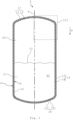
- the Fig.2 shows a schematic sectional view of an embodiment of a storage container 5 as mentioned above.
- the storage container 5 can also be referred to as a storage tank.
- the storage container 5 can also be used for other cryogenic liquids.
- the storage container 5 is constructed rotationally symmetrically to the axis of symmetry 6.
- the storage container 5 comprises an outer container 8 constructed rotationally symmetrically to the axis of symmetry and an inner container 9 constructed rotationally symmetrically to the axis of symmetry 6.
- the inner container 9 is arranged completely within the outer container 8.
- An insulating element 10 is provided between the outer container 8 and the inner container 9.
- the insulating element 10 can have a multilayer insulation layer (MLI) or can be designed as such.
- MMI multilayer insulation layer
- the outer container 8 comprises a tubular or cylindrical base section 11, which is constructed rotationally symmetrically to the axis of symmetry 6.
- the base section 11 is closed on both sides by means of a cover section 12 and a base section 13.
- the ceiling section 12 is arranged above the floor section 13.
- the base section 11 can have a circular or almost circular geometry in cross section.
- the ceiling section 12 and the floor section 13 are curved.
- the ceiling section 12 and the floor section 13 are curved in opposite directions, so that the ceiling section 12 and the floor section 13 are curved outwards with respect to the base section 11.
- the outer container 8 is fluid-tight, in particular gas-tight.
- the inner container 9 comprises, like the outer container 8, a tubular or cylindrical base section 14 which is constructed rotationally symmetrically to the axis of symmetry 6.
- the base section 14 is in the orientation of the Fig.2 closed on the top by a cover section 15 and on the bottom by a base section 16.
- the base section 14 can have a circular or almost circular geometry in cross section.
- the cover section 15 and the base section 16 are curved. In particular, the cover section 15 and the base section 16 are curved in opposite directions, so that the cover section 15 and the base section 16 are curved outwards with respect to the base section 14.
- the inner container 9 is fluid-tight, in particular gas-tight.
- the outer container 8 and/or the inner container 9 can have a blow-off valve (not shown).
- the two ceiling sections 12, 15 form a ceiling 17 of the storage tank 5 with the insulating element 10 lying between them.
- the two floor sections 13, 16 form a floor 18 of the storage tank 5 with the insulating element 10 lying between them, and the two base sections 11, 14 form a wall 19 of the storage tank 5 with the insulating element 10 lying between them, which wall 19 runs rotationally symmetrically around the axis of symmetry 6.
- the liquid hydrogen H2 is contained in the inner container 9. As long as the hydrogen H2 is in the two-phase region, a gas zone 20 with vaporized hydrogen H2 and a liquid zone 21 with liquid hydrogen H2 can be provided in the inner container 9.
- the hydrogen H2 therefore has When filled into the inner container 9, two phases with different states of aggregation, namely liquid and gaseous, are present. This means that in the inner container 9 there is a phase boundary 22 between the liquid hydrogen H2 and the gaseous hydrogen H2.
- fill level detection can be achieved by using a differential pressure method.
- a capacitive measurement can be carried out by changing the dielectric constant in the liquid hydrogen H2.
- these methods are complex. Due to the physical properties of hydrogen H2, reliable fill level detection is not possible or can only be implemented technically with great effort, since various physical quantities have to be measured and complexly calculated.
- the Fig.3 shows the detail view III according to the Fig.2 .
- the storage container 5 comprises a Fig.3 shown device 23 for displaying a predetermined fill level 24 with liquid hydrogen H2 in the storage container 5.
- the predetermined fill level 24 corresponds to the phase boundary 22.
- the predetermined fill level 24 is defined as a predetermined position of a liquid column of liquid hydrogen H2 held in the storage container 5.
- the predetermined fill level 24 can be reached, for example, when the storage container 5 is filled to 88% to 95% with liquid hydrogen H2.
- the predetermined fill level 24 can also be referred to as a limit value or predetermined limit value.
- the device 23 comprises a cell 25 which, when the predetermined filling level 24 is reached, is at least partially or completely immersed in the liquid hydrogen H2.
- the cell 25 is arranged inside the inner container 9 in the area of the ceiling 17.
- a "cell” is understood here to mean a closed volume.
- the cell 25 can be made of stainless steel.
- the cell 25 can be spherical. Alternatively, the cell 25 can also be cuboid-shaped or cylindrical.
- the geometry of the cell 25 is arbitrary.
- the cell 25 encloses an interior space 26 in which a gas G is accommodated, which liquefies when the cell 25 comes into contact with the liquid hydrogen H2.
- the cell 25 can therefore be referred to as a neon cell.
- other suitable gases can also be used.
- the boiling point of the gas G accommodated in the cell 25 is higher than the boiling point of the liquid hydrogen H2, so that the gas G liquefies when the cell 25 is immersed in the liquid hydrogen H2.
- the cell 25 is firmly mounted on the storage container 5 using a line 27.
- the line 27 is guided through the inner container 9, the insulating element 10 and the outer container 8.
- the line 27 is welded to the storage container 5.
- the gas G can be introduced into the cell 25 through the line 27.
- a nozzle 28 with a valve 29 can be provided on the line 27.
- the cell 25 can be filled with the gas G via the valve 29.
- the line 27 can be made of stainless steel.
- the device 23 also includes a pressure indicator 30, which indicates a pressure drop in the cell 25 when the gas G is liquefied and thus when the predetermined filling level 24 is reached.
- the pressure indicator 30 can be a manometer. However, the pressure indicator 30 can also be a pressure sensor or include a pressure sensor.
- the pressure indicator 30 can be attached to the nozzle 28. This means that both the valve 29 and the pressure indicator 30 can be mounted on the nozzle 28.
- the nozzle 28 can be welded or soldered to the line 27, for example.
- the device 23 further comprises a heating element 31 which is suitable for introducing heat W into the cell 25 or into the gas G.
- the cell 25 is thus heated.
- the cell 25 can therefore also be referred to as a heated cell, in particular as a heated neon cell.
- the heating element 31 can be an electrical heating element.
- the heating element 31 can be arranged in the interior 26. Alternatively, the heating element 31 can also be provided on the outside of the cell 25, for example.
- the heating element 31 is supplied with current by means of a cable 32 guided through the line 27.
- the cable 32 is guided centrally in the line 27 so that the gas G can be supplied around the cable 32 through an annular opening of the cell 25.
- the heating element 31 can be assigned a control unit 33 that is arranged outside the storage container 5.
- the control unit 33 is a switch that is actuated before or when the storage container 5 is filled in order to supply current to the heating element 31.
- the control unit 33 can, however, also be a computer or comprise a computer.
- the pressure display device 30 is a pressure sensor or comprises a pressure sensor
- the control unit 33 can also be suitable for processing a signal from the pressure display device 30.
- the predetermined fill level 24 can be selected so that the storage container 5 is 88 to 95% full when the predetermined fill level 24 is reached.
- filling must be stopped when the predetermined fill level 24 is reached in order to prevent the liquid hydrogen H2 from overflowing.
- the cell 25 is filled with the gas G or the cell 25 is already filled with the gas G.
- the heating element 31 is energized while the storage container 5 is being filled, so that it continuously provides about 5 W of heating power and introduces the heat W into the gas G.
- the gas G liquefies and a pressure drop occurs in the interior 26 of the cell 25, which can be displayed using the pressure display device 30.
- the heating power of the heating element 31 is dimensioned such that the gas G liquefies when the cell 25 is immersed in the liquid hydrogen H2 despite the heat W introduced.
- the heating element 31 ensures that the liquid gas G is evaporated again. This leads to a pressure increase in the cell 25.
- the pressure indicator 30 can then be used to detect that the hydrogen level has fallen below the predetermined filling level 24.
- the heating element 31 also ensures that the required heat input W is only required during the measurement task. A constant cold leak is thus excluded. A clear indication of the reaching of the specified filling level 24 is possible with the aid of the device 23.
- the Fig.4 shows a schematic block diagram of an embodiment of a method for indicating when the predetermined fill level 24 has been reached.
- the method is carried out with the aid of the device 23.
- the cell 25 arranged inside the storage container 5 is immersed in the liquid hydrogen H2.
- the immersion takes place when the predetermined fill level 24 is reached, that is to say when the hydrogen level in the storage container 5 rises to the predetermined fill level 24 and the liquid hydrogen at least partially flows around the cell 25.
- the cell 25 is therefore not immersed by moving the cell 25.
- the cell 25 is arranged in a stationary manner inside the inner container 9.
- a step S2 the gas G held in the cell 25 is liquefied with the aid of the liquid hydrogen H2.
- the liquid hydrogen H2 flows at least partially around the cell 25 and extracts heat from the gas G, causing it to liquefy.
- heat W is continuously introduced into the gas G with the aid of the heating element 31.
- the heating power is, for example, 5 W.
- the heat W introduced does not prevent the gas G from liquefying when the cell 25 is immersed in the liquid hydrogen H2.
- the gas G is evaporated again with the aid of the heat W introduced.
- a pressure drop in the cell 25 during the liquefaction of the gas G is displayed with the aid of the pressure display device 30.
- the pressure drop indicates that the predetermined filling level 24 has been reached.
- the pressure drop results from the phase transition of the gas G from its gaseous state to the liquid state.
- the pressure rises again as soon as the cell 25 is no longer immersed in the liquid hydrogen H2 and the gas G is liquefied with the aid of the heating element 31. is evaporated.
- the heat W is preferably introduced continuously into the gas G during all steps S1 to S4.
Landscapes
- Engineering & Computer Science (AREA)
- Mechanical Engineering (AREA)
- General Engineering & Computer Science (AREA)
- Physics & Mathematics (AREA)
- Fluid Mechanics (AREA)
- General Physics & Mathematics (AREA)
- Thermal Sciences (AREA)
- Filling Or Discharging Of Gas Storage Vessels (AREA)
- Measurement Of Levels Of Liquids Or Fluent Solid Materials (AREA)
Description
- Die Erfindung betrifft einen Speicherbehälter für flüssigen Wasserstoff aufweisend einen Außenbehälter, einen innerhalb des Außenbehälters angeordneten Innenbehälter und eine Vorrichtung zum Anzeigen eines Erreichens eines vorgegebenen Füllstands. Des Weiteren betrifft die vorliegende Erfindung ein Verfahren zum Anzeigen eines Erreichens eines vorgegebene Füllstands eines Speicherbehälters für flüssigen Wasserstoff.
- Speicherbehälter für flüssigen Wasserstoff weisen gemäß betriebsinternen Erkenntnissen der Anmelderin bezüglich des Außen- und Innenbehälters jeweils eine zylinderförmige Geometrie mit einem rohrförmigen Basisabschnitt sowie zwei gewölbten Deckelabschnitten auf, die den Basisabschnitt stirnseitig verschließen. Je nach Anforderung wird ein derartiger Speicherbehälter bis zu einem vorgegebenen Füllstand mit flüssigem Wasserstoff befüllt. Der vorgegebene Füllstand kann beispielsweise dann erreicht sein, wenn der Speicherbehälter zu etwa 88 bis 95% mit flüssigem Wasserstoff befüllt ist. Um ein Erreichen des vorgegebenen Füllstands zu detektieren oder anzuzeigen, ist der Anmelderin betriebsinterner Stand der Technik bekannt, bei dem eine Füllstandsanzeige mit Hilfe einer sogenannten Differenzdruckmethode verwirklicht wird. Ferner ist gemäß betriebsinternen Erkenntnissen der Anmelderin eine kapazitive Messung des Füllstands durch eine Veränderung der Dielektrizitätskonstante im flüssigen Wasserstoff möglich. Durch die physikalischen Eigenschaften von Wasserstoff ist eine zuverlässige Füllstandsanzeige jedoch technisch nur sehr aufwendig realisierbar. Hierbei ist es erforderlich, verschiedene physikalische Größen zu messen und komplex zu verrechnen.
- Vor diesem Hintergrund besteht die Aufgabe der vorliegenden Erfindung darin, einen bezüglich der Füllstandsmessung verbesserten Speicherbehälter für flüssigen Wasserstoff der eingangs genannten Art und ein verbessertes Füllstandsmessverfahren eines Speicherbehälters für flüssigen Wasserstoff bereitzustellen.
- Demgemäß wird ein Speicherbehälter für flüssigen Wasserstoff mit einem Außenbehälter, einem innerhalb des Außenbehälters angeordneten Innenbehälter und einer Vorrichtung zum Anzeigen eines Erreichens eines vorgegebenen Füllstands für den flüssigen Wasserstoff vorgeschlagen. Die Vorrichtung umfasst eine innerhalb des Innenbehälters angeordnete Zelle, welche mit einem Gas gefüllt ist, welches sich bei einem Eintauchen der Zelle in den flüssigen Wasserstoff verflüssigt, eine Druckanzeigeeinrichtung, welche einen Druckabfall in der Zelle bei einem Verflüssigen des Gases und damit das Erreichen des vorgegebenen Füllstands anzeigt, und ein Heizelement, welches kontinuierlich Wärme in das Gas einbringt.
- Dadurch, dass das Heizelement vorgesehen ist, ist gewährleistet, dass das Gas in der Zelle nicht verflüssigt, bevor der flüssige Wasserstoff die Zelle umspült bzw. ein vorgegebener Füllstand erreicht ist. Zudem wird gewährleistet, dass das Gas in der Zelle während eines erneuten Befüllens des Speicherbehälters sicher wieder verdampft und eine zuverlässige Füllstandsmessung auch in geschlossenen und hochisolierten Behältern, wie einem vorliegenden doppelwandigen Speicherbehälter für Wasserstoff möglich ist. Ferner ist der erforderliche Wärmeeintrag nur während des Befüllens des Speicherbehälters erforderlich. Ein konstantes Kälteleck wird somit ausgeschlossen. Die in
JPS54153267U - Die Vorrichtung kann auch als Anzeigevorrichtung, als Grenzwertgeber oder als Grenzwertgebervorrichtung bezeichnet werden. Der Speicherbehälter umfasst einen Außenbehälter, einen innerhalb des Außenbehälters angeordneten Innenbehälter sowie vorzugsweise ein zwischen dem Außenbehälter und dem Innenbehälter angeordnetes Dämmelement oder Isolierelement. Die Zelle ist innerhalb des Innenbehälters angeordnet. Die Vorrichtung kann neben flüssigem Wasserstoff auch für andere kryogene Flüssigkeiten eingesetzt werden. Beispiele für kryogene Fluide oder Flüssigkeiten, oder Kryogene, sind beispielsweise flüssiges Helium, flüssiger Stickstoff oder flüssiger Sauerstoff.
- Die Zelle wird dann, wenn der vorgegebene Füllstand erreicht wird, zumindest teilweise von dem flüssigen Wasserstoff umspült. Unter einer "Zelle" ist vorliegend ein Bauteil zu verstehen, das einen Innenraum umschließt, in welchem das Gas aufgenommen ist.
- Der Begriff "Zelle" kann vorliegend auch durch den Begriff "Behälter" bezeichnet werden. Die Zelle kann auch als Gaszelle oder als Gasbehälter bezeichnet werden.
- Das Gas kann ein beliebiges Gas sein, welches die Eigenschaft aufweist, dass dieses sich bei einem Eintauchen der Zelle in den flüssigen Wasserstoff verflüssigt. Aufgrund dieses Phasenübergangs des Gases von gasförmig zu flüssig kommt es in der Zelle zu einem Druckabfall, welcher von der Druckanzeigeeinrichtung erfasst oder angezeigt werden kann. Der Druckabfall ist somit eine Information, die das Erreichen des vorgegebenen Füllstands anzeigt.
- Die Druckanzeigeeinrichtung ist vorzugsweise außerhalb des Speicherbehälters angeordnet, so dass diese von einem Techniker eingesehen werden kann. Das Heizelement ist vorzugsweise ein elektrisches Heizelement. Das Heizelement kann beispielsweise ein elektrischer Widerstand sein. Die Zelle ist also beheizt und kann als beheizte Zelle bezeichnet werden. Dass das Heizelement die Wärme "kontinuierlich" in das Gas einbringt, bedeutet vorliegend, dass das Heizelement bevorzugt während eines gesamten Füllvorgangs oder Befüllvorgangs des Speicherbehälters mit dem flüssigen Wasserstoff bestromt wird und so die Wärme in das Gas einbringt. Das Heizelement bringt die Wärme somit bereits vor dem Eintauchen der Zelle in den flüssigen Wasserstoff in das Gas ein. Dabei wird jedoch nur so viel Wärme in das Gas eingebracht, dass dieses sich bei dem Eintauchen der Zelle in den flüssigen Wasserstoff verflüssigt.
- Sobald die Zelle nicht mehr von dem flüssigen Wasserstoff umspült wird beziehungsweise nicht mehr in diesen eingetaucht ist, wird das Gas durch die von dem Heizelement eingebrachte Wärme wieder verdampft. Es kommt dann in der Zelle wieder zu einem Druckanstieg, der ein Abfallen des Flüssigkeitspegels des flüssigen Wasserstoffs unter den vorgegebenen Füllstand anzeigt. Es wird also nur so viel Wärme in das Gas eingebracht, dass sich das Gas bei dem Eintauchen der Zelle in den flüssigen Wasserstoff verflüssigt und dass das Gas wieder verdampft, sobald die Zelle nicht mehr in den flüssigen Wasserstoff eingetaucht ist.
- Beispielsweise bringt das Heizelement während des Füllvorgangs kontinuierlich eine Wärmeleistung von 5 W in das Gas ein. Nach Beendigung des Füllvorgangs wird das Heizelement bevorzugt nicht mehr bestromt. Aufgrund des Heizelements ist es zum Verdampfen des Gases nicht erforderlich, von extern des Speicherbehälters Wärme in die Zelle beziehungsweise in das Gas einzubringen. Hierdurch kann, wie zuvor erwähnt, ein konstantes Kälteleck, über welches Wärme von extern in die Zelle eingebracht wird, ausgeschlossen werden.
- Gemäß einer Ausführungsform ist das Gas Neon.
- Es kann jedoch auch ein beliebiges anderes Gas eingesetzt werden. Insbesondere ist der Siedepunkt des in der Zelle aufgenommenen Gases höher als der Siedepunkt des flüssigen Wasserstoffs, so dass sich das Gas bei dem Eintauchen der Zelle in den flüssigen Wasserstoff verflüssigt. Die Zelle kann als Neonzelle, insbesondere als beheizte Neonzelle, bezeichnet werden.
- Gemäß einer weiteren Ausführungsform ist die Zelle kugelförmig.
- Hierdurch ergibt sich bei größtmöglichem Volumen eine kleinstmögliche Oberfläche der Zelle. Die Zelle kann jedoch auch zylinderförmig oder quaderförmig sein oder jede beliebige andere Geometrie aufweisen.
- Gemäß einer weiteren Ausführungsform umfasst die Vorrichtung ferner eine Leitung, welche die Zelle trägt.
- Die Leitung ist insbesondere durch eine Wandung des Speicherbehälters hindurchgeführt. Die Leitung kann beispielsweise eine Edelstahlleitung sein. Die Zelle kann an der Leitung derart aufgehängt sein, dass die Leitung eine Gewichtskraft der Zelle aufnimmt. Die Leitung hält die Zelle in einer vorgegebenen Position fixiert. Die Zelle kann also nicht auf dem flüssigen Wasserstoff aufschwimmen.
- Gemäß einer weiteren Ausführungsform ist der Zelle das Gas mit Hilfe der Leitung zuführbar, wobei ein Kabel zum Bestromen des Heizelements durch die Leitung hindurch zu der Zelle geführt ist.
- Die Leitung kann somit eine Doppelfunktion erfüllen, nämlich das Zuführen des Gases zu der Zelle und das Aufnehmen des Kabels, welches zu dem Heizelement führt. Insbesondere ist das Kabel mittig in der Leitung aufgenommen. Das Kabel kann in einem Schutzrohr aufgenommen sein, das mittig in der Leitung angeordnet ist.
- Gemäß einer weiteren Ausführungsform umfasst die Vorrichtung ferner ein Ventil, mit dessen Hilfe das Gas der Leitung zuführbar ist.
- An der Leitung kann ein Stutzen vorgesehen sein, an welchem das Ventil angebracht ist. Mit Hilfe des Ventils kann das Gas nachgefüllt werden oder das Gas kann vor dem Befüllen des Speicherbehälters in die Zelle eingebracht werden.
- Gemäß einer weiteren Ausführungsform ist die Druckanzeigeeinrichtung mit der Leitung in Fluidverbindung.
- Über die Leitung ist die Druckanzeigeeinrichtung mit der Zelle in Fluidverbindung. "In Fluidverbindung" bedeutet vorliegend, dass das Gas von der Zelle über die Leitung zu der Druckanzeigeeinrichtung und umgekehrt strömen kann. Die Druckanzeigeeinrichtung kann an dem zuvor erwähnten Stutzen angebracht sein, der auch das Ventil trägt.
- Gemäß einer weiteren Ausführungsform ist die Druckanzeigeeinrichtung ein Manometer.
- Hierdurch ist ein einfacher Aufbau der Vorrichtung möglich. Ein den Speicherbehälter befüllender Techniker kann anhand des Druckabfalls einfach erkennen, dass der vorgegebene Füllstand erreicht ist. Die Druckanzeigeeinrichtung kann jedoch auch ein Drucksensor sein oder einen Drucksensor umfassen.
- Gemäß einer weiteren Ausführungsform ist das Heizelement innerhalb eines von der Zelle umschlossenen Innenraums der Zelle angeordnet.
- Hierdurch kommt das Heizelement nicht mit dem flüssigen Wasserstoff in Kontakt. Alternativ kann das Heizelement jedoch auch außenseitig an der Zelle vorgesehen sein. Besonders bevorzugt ist das Heizelement jedoch in dem Innenraum der Zelle angeordnet. In dem Innenraum ist auch das Gas aufgenommen.
- Gemäß einer weiteren Ausführungsform umfasst die Vorrichtung ferner eine Steuereinheit zum Ansteuern des Heizelements.
- Die Steuereinheit kann im einfachsten Fall ein Schalter sein, der es ermöglicht, das Heizelement über das durch die Leitung geführte Kabel zu bestromen. Die Steuereinheit kann jedoch auch ein Rechner sein oder einen Rechner umfassen. Für den Fall, dass die Druckanzeigeeinrichtung ein Drucksensor ist oder einen Drucksensor umfasst, kann die Steuereinheit auch geeignet sein, Sensorsignale der Druckanzeigeeinrichtung zu erfassen, auszuwerten und/oder anzuzeigen.
- Der Speicherbehälter ist insbesondere für maritime Anwendungen geeignet. Der Speicherbehälter kann daher als maritimer Speicherbehälter bezeichnet werden. Beispielsweise kann der Speicherbehälter an einem Fahrzeug, insbesondere an einem Wasserfahrzeug, montiert sein. Demgemäß wird auch ein Fahrzeug, insbesondere ein Wasserfahrzeug, mit einem derartigen Speicherbehälter vorgeschlagen. Der Speicherbehälter kann auch als Speichertank, als Wasserstoff-Speicherbehälter oder als Wasserstoff-Speichertank bezeichnet werden. Der Speicherbehälter ist vorzugsweise zum Aufnehmen von flüssigem Wasserstoff geeignet. Der Speicherbehälter kann jedoch auch für andere kryogene Flüssigkeiten eingesetzt werden. Beispiele für kryogene Fluide oder Flüssigkeiten, oder Kryogene, sind beispielsweise flüssiges Helium, flüssiger Stickstoff oder flüssiger Sauerstoff.
- In dem Speicherbehälter bildet sich nach oder bei dem Einfüllen des Wasserstoffs eine Gaszone mit gasförmigem Wasserstoff sowie eine darunterliegende Flüssigkeitszone mit flüssigem Wasserstoff. Zwischen der Gaszone und der Flüssigkeitszone ist eine Phasengrenze vorgesehen. Sobald die Phasengrenze den vorgegebenen Füllstand erreicht, ist der Speicherbehälter gefüllt. Der Wasserstoff weist also nach dem Einfüllen in den Speicherbehälter zwei Phasen mit unterschiedlichen Aggregatszuständen, nämlich flüssig und gasförmig, auf. Der Wasserstoff kann von der flüssigen Phase in die gasförmige Phase und umgekehrt übergehen.
- Gemäß einer Ausführungsform ist eine die Zelle tragende Leitung der Vorrichtung fest mit einer Wandung des Speicherbehälters verbunden.
- Beispielsweise kann die Leitung in die Wandung eingeschweißt sein. Die Leitung ist vorzugsweise eine Edelstahlleitung.
- Der Speicherbehälter umfasst, wie vorstehend ausgeführt, einen Außenbehälter und einen innerhalb des Außenbehälters angeordneten Innenbehälter, wobei die Zelle innerhalb des Innenbehälters angeordnet ist. Vorzugsweise sind der Außenbehälter und der Innenbehälter aus Edelstahl gefertigt. Zwischen dem Außenbehälter und dem Innenbehälter kann ein Dämmelement oder Isolierelement zur Wärmedämmung vorgesehen sein. Das Isolierelement dient der Wärmedämmung des Innenbehälters. Die zuvor erwähnte Leitung kann mit dem Außenbehälter und mit dem Innenbehälter verschweißt sein.
- Weiterhin wird ein Verfahren zum Anzeigen eines Erreichens eines vorgegebenen Füllstands eines Speicherbehälters für flüssigen Wasserstoff aufweisend einen Außenbehälter, einen innerhalb des Außenbehälters angeordneten Innenbehälter vorgeschlagen. Das Verfahren umfasst die folgenden Schritte: a) Eintauchen einer innerhalb des Innenbehälters angeordneten Zelle in den flüssigen Wasserstoff bei Erreichen des vorgegebenen Füllstands, wobei die Zelle dadurch in den flüssigen Wasserstoff eintaucht, dass der Wasserstoffpegel oder Flüssigkeitspegel des flüssigen Wasserstoffs innerhalb des Innenbehälters bis zu dem vorgegebenen Füllstand ansteigt und die Zelle von dem flüssigen Wasserstoff zumindest teilweise umspült wird, b) Verflüssigen eines in der Zelle aufgenommenen Gases mit Hilfe des flüssigen Wasserstoffs, c) kontinuierliches Einbringen von Wärme in das Gas mit Hilfe eines Heizelements, und d) Anzeigen eines Druckabfalls in der Zelle bei dem Verflüssigen des Gases und damit des Erreichens des vorgegebenen Füllstands mit Hilfe einer Druckanzeigeeinrichtung.
- Sobald die Zelle zumindest teilweise von dem flüssigen Wasserstoff umspült wird, verflüssigt sich das in der Zelle aufgenommene Gas. Dabei wird mit Hilfe des Heizelements nur so viel Wärme in das Gas eingebracht, dass dieses sich beim Umspülen der Zelle mit dem flüssigen Wasserstoff trotz des Wärmeeintrags verflüssigt. Der Phasenübergang des Gases von gasförmig zu flüssig führt zu einem Druckabfall in der Zelle, der mit Hilfe der Druckanzeigeeinrichtung angezeigt wird. Der Druckabfall ist somit ein Indiz dafür, dass der vorgegebene Füllstand erreicht ist. Sobald die Zelle jedoch nicht mehr in den flüssigen Wasserstoff eingetaucht ist, wird das Gas mit Hilfe des Heizelements wieder verdampft. Dieser Phasenübergang führt zu einem Druckanstieg in der Zelle, der ebenfalls mit Hilfe der Druckanzeigeeinrichtung angezeigt wird. Der Druckanstieg ist ein Indiz dafür, dass der Wasserstoffpegel unter den vorgegebenen Füllstand abgefallen ist.
- Gemäß einer Ausführungsform wird die Wärme während der Schritte a), b), c) und d) in das Gas eingebracht. Das heißt, die Wärme wird vorzugsweise während des gesamten Befüllvorgangs des Speicherbehälters mit dem flüssigen Wasserstoff in das Gas eingebracht. Bevorzugt bringt das Heizelement ausschließlich während des Befüllvorgangs Wärme in das Gas ein. Außerhalb eines Befüllvorgangs bringt das Heizelement vorzugsweise keine Wärme in das Gas ein. Im Falle eines elektrischen Heizelements wird dieses bevorzugt ausschließlich während des Befüllvorgangs bestromt. Somit wird das elektrische Heizelement vorzugsweise außerhalb des Befüllvorgangs nicht bestromt.
- Die für für den Speicherbehälter erläuterten Ausführungsformen und Erläuterungen gelten für das Verfahren entsprechend und umgekehrt.
- "Ein" ist vorliegend nicht zwingend beschränkend auf genau ein Element zu verstehen. Vielmehr können auch mehrere Elemente, wie beispielsweise zwei, drei oder mehr, vorgesehen sein. Auch jedes andere hier verwendete Zählwort ist nicht dahingehend zu verstehen, dass eine Beschränkung auf genau die genannte Anzahl an Elementen gegeben ist. Vielmehr sind zahlenmäßige Abweichungen nach oben und nach unten möglich, soweit nichts Gegenteiliges angegeben ist.
- Weitere vorteilhafte Ausgestaltungen und Aspekte des Speicherbehälters und/oder des Verfahrens sind Gegenstand der Unteransprüche.
- Im Weiteren werden der Speicherbehälter und/oder das Verfahren anhand von bevorzugten Ausführungsformen unter Bezugnahme auf die beigelegten Figuren näher erläutert.
-
Fig. 1 zeigt eine schematische Seitenansicht einer Ausführungsform eines Fahrzeugs; -
Fig. 2 zeigt eine schematische Schnittansicht einer Ausführungsform eines Speicherbehälters für das Fahrzeug gemäßFig. 1 ; -
Fig. 3 zeigt die Detailansicht III gemäßFig. 2 ; und -
Fig. 4 zeigt ein schematisches Blockdiagramm einer Ausführungsform eines Verfahrens zum Anzeigen eines Erreichens eines vorgegebenen Füllstands des Speicherbehälters gemäßFig. 2 . - In den Figuren sind gleiche oder funktionsgleiche Elemente mit denselben Bezugszeichen versehen worden, sofern nichts anderes angegeben ist.
- Die
Fig. 1 zeigt eine stark vereinfachte schematische Seitenansicht einer Ausführungsform eines Fahrzeugs 1. Das Fahrzeug 1 kann beispielsweise ein maritimes Wasserfahrzeug, insbesondere ein Schiff, sein. Das Fahrzeug 1 kann als maritimes Fahrzeug bezeichnet werden. Insbesondere kann das Fahrzeug 1 eine maritime Personenfähre sein. Alternativ kann das Fahrzeug 1 auch ein Landfahrzeug sein. Nachfolgend wird jedoch davon ausgegangen, dass das Fahrzeug 1 ein Wasserfahrzeug ist. - Das Fahrzeug 1 umfasst einen Rumpf 2, der schwimmfähig ist. An oder auf dem Rumpf 2 ist eine Brücke 3 vorgesehen. Das Fahrzeug 1 wird vorzugsweise mit Wasserstoff betrieben. Hierzu kann das Fahrzeug 1 eine Brennstoffzelle 4 aufweisen. Unter einer "Brennstoffzelle" ist vorliegend eine galvanische Zelle zu verstehen, welche die chemische Reaktionsenergie eines kontinuierlich zugeführten Brennstoffs, vorliegend Wasserstoff, und eines Oxidationsmittels, vorliegend Sauerstoff, in elektrische Energie wandelt. Mit Hilfe der erhaltenen elektrischen Energie kann beispielsweise ein nicht gezeigter Elektromotor angetrieben werden, der wiederum eine Schiffsschraube zum Antreiben des Fahrzeugs 1 antreibt.
- Zum Versorgen der Brennstoffzelle 4 mit Wasserstoff ist ein Speicherbehälter 5 zum Speichern von flüssigem Wasserstoff vorgesehen. Der Speicherbehälter 5 ist rotationssymmetrisch zu einer Mittel- oder Symmetrieachse 6 aufgebaut. Der Speicherbehälter 5 kann beispielsweise innerhalb des Rumpfs 2, insbesondere innerhalb eines Maschinenraums, auf der Brücke 3 oder auf einem als Fundament 7 fungierenden Deck des Rumpfs 2 angeordnet sein. Dabei ist die Symmetrieachse 6 entlang einer Schwerkraftrichtung g orientiert. Das heißt, der Speicherbehälter 5 ist aufrecht oder vertikal positioniert. Somit ist die Symmetrieachse 6 senkrecht zu dem Fundament 7 platziert. Für den Fall, dass das Fahrzeug 1 beispielsweise ein auf einen Wasserstoffantrieb umgerüstetes Fahrzeug ist, kann der Speicherbehälter 5 beispielsweise auch in einem Kamin oder Schornstein des Fahrzeugs 1 platziert sein.
- Die
Fig. 2 zeigt eine schematische Schnittansicht einer Ausführungsform eines wie zuvor erwähnten Speicherbehälters 5. Der Speicherbehälter 5 kann auch als Speichertank bezeichnet werden. Wie zuvor erwähnt, ist der Speicherbehälter 5 zur Aufnahme von flüssigem Wasserstoff H2 (Siedepunkt 1 bara: 20,268 K = -252,882 °C) geeignet. Daher kann der Speicherbehälter 5 auch als Wasserstoff-Speicherbehälter oder als Wasserstoff-Speichertank bezeichnet werden. Der Speicherbehälter 5 kann jedoch auch für andere kryogene Flüssigkeiten eingesetzt werden. Beispiele für kryogene Fluide oder Flüssigkeiten, oder kurz Kryogene, sind neben dem zuvor erwähnten flüssigen Wasserstoff H2 flüssiges Helium He (Siedepunkt 1 bara: 4,222 K = -268,928 °C), flüssiger Stickstoff N2 (Siedepunkt 1 bara: 77,35 K = -195,80 °C) oder flüssiger Sauerstoff O2 (Siedepunkt 1 bara: 90,18 K = -182,97 °C). - Der Speicherbehälter 5 ist rotationssymmetrisch zu der Symmetrieachse 6 aufgebaut. Der Speicherbehälter 5 umfasst einen rotationssymmetrisch zu der Symmetrieachse aufgebauten Außenbehälter 8 sowie einen rotationssymmetrisch zu der Symmetrieachse 6 aufgebauten Innenbehälter 9. Der Innenbehälter 9 ist dabei vollständig innerhalb des Außenbehälters 8 angeordnet. Zwischen dem Außenbehälter 8 und dem Innenbehälter 9 ist ein Dämmungselement oder Isolierelement 10 vorgesehen. Das Isolierelement 10 kann eine mehrlagige Isolationsschicht (Engl.: Multilayer Insulation, MLI) aufweisen oder als solche ausgebildet sein.
- Der Außenbehälter 8 umfasst einen rohr- oder zylinderförmigen Basisabschnitt 11, der rotationssymmetrisch zu der Symmetrieachse 6 aufgebaut ist. Der Basisabschnitt 11 ist stirnseitig beidseits jeweils mit Hilfe eines Deckenabschnitts 12 und eines Bodenabschnitts 13 verschlossen. In der Orientierung der
Fig. 2 beziehungsweise entlang der Schwerkraftrichtung g betrachtet ist dabei der Deckenabschnitt 12 oberhalb des Bodenabschnitts 13 angeordnet. Der Basisabschnitt 11 kann im Querschnitt eine kreisrunde oder annähernd kreisrunde Geometrie aufweisen. Der Deckenabschnitt 12 und der Bodenabschnitt 13 sind gewölbt. Der Deckenabschnitt 12 und der Bodenabschnitt 13 sind gegensinnig gewölbt, so dass der Deckenabschnitt 12 und der Bodenabschnitt 13 bezüglich des Basisabschnitts 11 nach außen gewölbt sind. Der Außenbehälter 8 ist fluiddicht, insbesondere gasdicht. - Der Innenbehälter 9 umfasst, wie der Außenbehälter 8, einen rohr- oder zylinderförmigen Basisabschnitt 14, der rotationssymmetrisch zu der Symmetrieachse 6 aufgebaut ist. Der Basisabschnitt 14 ist in der Orientierung der
Fig. 2 oberseitig von einem Deckenabschnitt 15 und unterseitig von einem Bodenabschnitt 16 verschlossen. Der Basisabschnitt 14 kann im Querschnitt eine kreisrunde oder annähernd kreisrunde Geometrie aufweisen. Der Deckenabschnitt 15 und der Bodenabschnitt 16 sind gewölbt. Insbesondere sind der Deckenabschnitt 15 und der Bodenabschnitt 16 gegensinnig gewölbt, so dass der Deckenabschnitt 15 und der Bodenabschnitt 16 bezüglich des Basisabschnitts 14 nach außen gewölbt sind. Der Innenbehälter 9 ist fluiddicht, insbesondere gasdicht. Der Außenbehälter 8 und/oder der Innenbehälter 9 können ein nicht gezeigtes Abblasventil aufweisen. - Die beiden Deckenabschnitte 12, 15 bilden mit dem zwischen diesen liegenden Isolierelement 10 eine Decke 17 des Speicherbehälters 5. Die beiden Bodenabschnitte 13, 16 bilden mit dem zwischen diesen liegenden Isolierelement 10 einen Boden 18 des Speicherbehälters 5, und die beiden Basisabschnitte 11, 14 bilden mit dem zwischen diesen liegenden Isolierelement 10 eine rotationssymmetrisch um die Symmetrieachse 6 umlaufende Wandung 19 des Speicherbehälters 5.
- In dem Innenbehälter 9 ist der flüssige Wasserstoff H2 aufgenommen. In dem Innenbehälter 9 können, solange sich der Wasserstoff H2 im Zweiphasengebiet befindet, eine Gaszone 20 mit verdampften Wasserstoff H2 und eine Flüssigkeitszone 21 mit flüssigem Wasserstoff H2 vorgesehen sein. Der Wasserstoff H2 weist also nach dem Einfüllen in den Innenbehälter 9 zwei Phasen mit unterschiedlichen Aggregatzuständen, nämlich flüssig und gasförmig, auf. Das heißt, in dem Innenbehälter 9 befindet sich eine Phasengrenze 22 zwischen dem flüssigen Wasserstoff H2 und dem gasförmigen Wasserstoff H2.
- Bei einem Befüllen eines derartigen Speicherbehälters 5 mit flüssigem Wasserstoff H2 ist es erforderlich, erfassen zu können, wann der Speicherbehälter 5 vollständig gefüllt ist beziehungsweise wann ein vorgegebener Füllstand in dem Speicherbehälter 5 erreicht wird. Hierdurch wird ein Überlaufen des flüssigen Wasserstoffs H2 verhindert. Es kann beispielsweise eine Füllstandserkennung dadurch verwirklich werden, dass eine Differenzdruckmethode angewandt wird. Ferner kann eine kapazitive Messung durch eine Veränderung der Dielektrizitätskonstante im flüssigen Wasserstoff H2 erfolgen. Diese Verfahren sind jedoch aufwendig. Durch die physikalischen Eigenschaften von Wasserstoff H2 ist eine zuverlässige Füllstandserkennung nicht gegeben beziehungsweise ist technisch nur sehr aufwendig realisierbar, da verschiedene physikalische Größen gemessen und komplex verrechnet werden müssen.
- Die
Fig. 3 zeigt die Detailansicht III gemäß derFig. 2 . Der Speicherbehälter 5 umfasst eine lediglich in derFig. 3 gezeigte Vorrichtung 23 zum Anzeigen eines vorgegebenen Füllstands 24 mit flüssigem Wasserstoff H2 in dem Speicherbehälter 5. Für den Fall, dass der Speicherbehälter 5 vollständig gefüllt ist, entspricht der vorgegebene Füllstand 24 der Phasengrenze 22. Der vorgegebene Füllstand 24 ist definiert als eine vorgegebene Position einer in dem Speicherbehälter 5 aufgenommenen Flüssigkeitssäule des flüssigen Wasserstoffs H2. Der vorgegebene Füllstand 24 kann beispielsweise dann erreicht sein, wenn der Speicherbehälter 5 zu 88% bis 95% mit flüssigem Wasserstoff H2 befüllt ist. Der vorgegebene Füllstand 24 kann auch als Grenzwert oder vorgegebener Grenzwert bezeichnet werden. - Die Vorrichtung 23 umfasst eine Zelle 25, die dann, wenn der vorgegebene Füllstand 24 erreicht ist, zumindest teilweise oder vollständig in dem flüssigen Wasserstoff H2 eingetaucht ist. Die Zelle 25 ist innerhalb des Innenbehälters 9 im Bereich der Decke 17 angeordnet. Unter einer "Zelle" ist vorliegend ein abgeschlossenes Volumen zu verstehen. Die Zelle 25 kann aus Edelstahl gefertigt sein. Die Zelle 25 kann kugelförmig sein. Alternativ kann die Zelle 25 auch quaderförmig oder zylinderförmig sein. Die Geometrie der Zelle 25 ist beliebig.
- Die Zelle 25 umschließt einen Innenraum 26, in dem ein Gas G aufgenommen ist, das sich bei einem Kontakt der Zelle 25 mit dem flüssigen Wasserstoff H2 verflüssigt. Das Gas G kann beispielsweise Neon Ne (Siedepunkt 1 bara: 27,07 K = -246,08 °C) sein. Die Zelle 25 kann daher als Neonzelle bezeichnet werden. Es können jedoch auch andere geeignete Gase eingesetzt werden. Dabei ist der Siedepunkt des in der Zelle 25 aufgenommenen Gases G höher als der Siedepunkt des flüssigen Wasserstoffs H2, so dass sich das Gas G bei dem Eintauchen der Zelle 25 in den flüssigen Wasserstoff H2 verflüssigt.
- Die Zelle 25 ist mit Hilfe einer Leitung 27 fest an dem Speicherbehälter 5 montiert. Die Leitung 27 ist durch den Innenbehälter 9, das Isolierelement 10 und den Außenbehälter 8 hindurchgeführt. Beispielsweise ist die Leitung 27 mit dem Speicherbehälter 5 verschweißt. Durch die Leitung 27 kann das Gas G in die Zelle 25 eingebracht werden. Hierzu kann an der Leitung 27 ein Stutzen 28 mit einem Ventil 29 vorgesehen sein. Über das Ventil 29 kann die Zelle 25 mit dem Gas G befüllt werden. Die Leitung 27 kann aus Edelstahl gefertigt sein.
- Ferner umfasst die Vorrichtung 23 eine Druckanzeigeeinrichtung 30, welche einen Druckabfall in der Zelle 25 bei einem Verflüssigen des Gases G und damit ein Erreichen des vorgegebenen Füllstands 24 anzeigt. Die Druckanzeigeeinrichtung 30 kann ein Manometer sein. Die Druckanzeigeeinrichtung 30 kann jedoch auch ein Drucksensor sein oder einen Drucksensor umfassen. Die Druckanzeigeeinrichtung 30 kann an dem Stutzen 28 angebracht sein. Das heißt, an dem Stutzen 28 kann sowohl das Ventil 29 als auch die Druckanzeigeeinrichtung 30 montiert sein. Der Stutzen 28 kann beispielsweise mit der Leitung 27 verschweißt oder verlötet sein.
- Die Vorrichtung 23 umfasst ferner ein Heizelement 31, das geeignet ist, Wärme W in die Zelle 25 beziehungsweise in das Gas G einzubringen. Die Zelle 25 ist somit beheizt. Die Zelle 25 kann daher auch als beheizte Zelle, insbesondere als beheizte Neonzelle, bezeichnet werden. Das Heizelement 31 kann ein elektrisches Heizelement sein. Das Heizelement 31 kann in dem Innenraum 26 angeordnet sein. Alternativ kann das Heizelement 31 beispielsweise auch außenseitig an der Zelle 25 vorgesehen sein.
- Das Heizelement 31 wird mit Hilfe eines durch die Leitung 27 geführten Kabels 32 bestromt. Das Kabel 32 ist dabei mittig in der Leitung 27 geführt, so dass das Gas G um das Kabel 32 herum durch eine ringförmige Öffnung der Zelle 25 zugeführt werden kann.
- Dem Heizelement 31 kann eine Steuereinheit 33 zugeordnet sein, die außerhalb des Speicherbehälters 5 angeordnet ist. Im einfachsten Fall ist die Steuereinheit 33 ein Schalter, der vor oder bei einem Befüllen des Speicherbehälters 5 betätigt wird, um das Heizelement 31 zu bestromen. Die Steuereinheit 33 kann jedoch auch ein Rechner sein oder einen Rechner umfassen. Die Steuereinheit 33 kann für den Fall, dass die Druckanzeigeeinrichtung 30 ein Drucksensor ist oder einen Drucksensor umfasst, auch geeignet sein, ein Signal der Druckanzeigeeinrichtung 30 zu verarbeiten.
- Die Funktionalität der Vorrichtung 23 wird nachfolgend erläutert. Je nach Anforderung kann der vorgegebene Füllstand 24 so gewählt werden, dass der Speicherbehälter 5 bei dem Erreichen des vorgegebenen Füllstands 24 zu 88 bis 95% befüllt ist. Bei dem Befüllen des Speicherbehälters 5 muss das Befüllen bei dem Erreichen des vorgegebenen Füllstands 24 beendet werden, um ein Überlaufen des flüssigen Wasserstoffs H2 zu verhindern. Vor dem Befüllen des Speicherbehälters 5 wird die Zelle 25 mit dem Gas G befüllt oder die Zelle 25 ist bereits mit dem Gas G befüllt.
- Das Heizelement 31 wird während dem Befüllen des Speicherbehälters 5 bestromt, so dass dieses kontinuierlich etwa 5 W Heizleistung bereitstellt und die Wärme W in das Gas G einbringt. Bei dem Eintauchen der Zelle 25 in den flüssigen Wasserstoff H2, das heißt wenn der vorgegebene Füllstand 24 erreicht ist und die Zelle 25 zumindest teilweise von flüssigem Wasserstopff umspült wird, verflüssigt sich das Gas G, und es kommt zu einem Druckabfall in dem Innenraum 26 der Zelle 25, welcher mit Hilfe der Druckanzeigeeinrichtung 30 angezeigt werden kann. Die Heizleistung des Heizelements 31 ist dabei so bemessen, dass sich das Gas G bei dem Eintauchen der Zelle 25 in den flüssigen Wasserstoff H2 trotz der eingebrachten Wärme W verflüssigt. Bei einem sinkendem Wasserstoffpegel wird mit Hilfe des Heizelements 31 gewährleistet, dass das flüssige Gas G wieder verdampft wird. Dies führt zu einem Druckanstieg in der Zelle 25. Anhand der Druckanzeigeeinrichtung 30 kann dann erkannt werden, dass der Wasserstoffpegel unter den vorgegebenen Füllstand 24 abgesunken ist.
- Mit Hilfe des Heizelements 31 ist auch gewährleistet, dass der erforderliche Eintrag der Wärme W nur während der Messaufgabe erforderlich ist. Ein konstantes Kälteleck wird somit ausgeschlossen. Eine eindeutige Indikation des Erreichens des vorgegebenen Füllstands 24 ist mit Hilfe der Vorrichtung 23 möglich.
- Die
Fig. 4 zeigt ein schematisches Blockdiagramm einer Ausführungsform eines Verfahrens zum Anzeigen des Erreichens des vorgegeben Füllstands 24. Das Verfahren wird mit Hilfe der Vorrichtung 23 durchgeführt. In einem Schritt S1 wird die innerhalb des Speicherbehälters 5 angeordnete Zelle 25 in den flüssigen Wasserstoff H2 eingetaucht. Das Eintauchen erfolgt bei dem Erreichen des vorgegebenen Füllstands 24, das heißt, wenn der Wasserstoffpegel in dem Speicherbehälter 5 bis zu dem vorgegebenen Füllstand 24 ansteigt und der flüssige Wasserstoff die Zelle 25 zumindest teilweise umspült. Ein Eintauchen der Zelle 25 erfolgt also nicht durch Bewegen der Zelle 25. Die Zelle 25 ist ortsfest innerhalb des Innenbehälters 9 angeordnet. - In einem Schritt S2 wird das in der Zelle 25 aufgenommene Gas G mit Hilfe des flüssigen Wasserstoffs H2 verflüssigt. Der flüssige Wasserstoff H2 umspült hierbei zumindest teilweise die Zelle 25 und entzieht dem Gas G Wärme, wodurch es sich verflüssigt. Gleichzeitig wird mit Hilfe des Heizelements 31 in einem Schritt S3 kontinuierlich Wärme W in das Gas G eingebracht. Die Heizleistung beträgt beispielsweise 5 W. Die eingebrachte Wärme W verhindert jedoch nicht das Verflüssigen des Gases G, wenn die Zelle 25 in den flüssigen Wasserstoff H2 eintaucht. Sobald die Zelle 25 nicht mehr in den flüssigen Wasserstoff H2 eingetaucht ist bzw. nicht mehr von flüssigem Wasserstoff umspült bzw. umgeben ist, wird das Gas G mit Hilfe der eingebrachten Wärme W wieder verdampft.
- In einem Schritt S4 wird mit Hilfe der Druckanzeigeeinrichtung 30 ein Druckabfall in der Zelle 25 bei dem Verflüssigen des Gases G angezeigt. Der Druckabfall wiederum zeigt an, dass der vorgegebene Füllstand 24 erreicht ist. Der Druckabfall resultiert aus dem Phasenübergang des Gases G von dessen gasförmigem Zustand in den flüssigen Zustand. Umgekehrt steigt der Druck wieder an, sobald die Zelle 25 nicht mehr in den flüssigen Wasserstoff H2 eingetaucht ist und das Gas G mit Hilfe des Heizelements 31 verdampft wird. Die Wärme W wird bevorzugt kontinuierlich während aller Schritte S1 bis S4 in das Gas G eingebracht.
-
- 1
- Fahrzeug
- 2
- Rumpf
- 3
- Brücke
- 4
- Brennstoffzelle
- 5
- Speicherbehälter
- 6
- Symmetrieachse
- 7
- Fundament
- 8
- Außenbehälter
- 9
- Innenbehälter
- 10
- Isolierelement
- 11
- Basisabschnitt
- 12
- Deckenabschnitt
- 13
- Bodenabschnitt
- 14
- Basisabschnitt
- 15
- Deckenabschnitt
- 16
- Bodenabschnitt
- 17
- Decke
- 18
- Boden
- 19
- Wandung
- 20
- Gaszone
- 21
- Flüssigkeitszone
- 22
- Phasengrenze
- 23
- Vorrichtung
- 24
- Füllstand
- 25
- Zelle
- 26
- Innenraum
- 27
- Leitung
- 28
- Stutzen
- 29
- Ventil
- 30
- Druckanzeigeeinrichtung
- 31
- Heizelement
- 32
- Kabel
- 33
- Steuereinheit
- g
- Schwerkraftrichtung
- G
- Gas
- H2
- Wasserstoff
- S1
- Schritt
- S2
- Schritt
- S3
- Schritt
- S4
- Schritt
- W
- Wärme
Claims (13)
- Speicherbehälter (5) für flüssigen Wasserstoff (H2) aufweisend eine Vorrichtung (23) zum Anzeigen eines Erreichens eines vorgegeben Füllstands (24) des flüssigen Wasserstoffs (H2) mit einer Zelle (25), welche mit einem Gas (G) gefüllt ist, welches sich bei einem Eintauchen der Zelle (25) in den flüssigen Wasserstoff (H2) verflüssigt, einer Druckanzeigeeinrichtung (30), welche einen Druckabfall in der Zelle (25) bei einem Verflüssigen des Gases (G) und damit das Erreichen des vorgegebenen Füllstands (24) anzeigt, gekennzeichnet durch einen Außenbehälter (8) und einen innerhalb des Außenbehälters (8) angeordneten Innenbehälter (9), wobei die Zelle (25) innerhalb des Innenbehälters (9) angeordnet ist, und einem Heizelement (31), welches kontinuierlich Wärme (W) in das Gas (G) einbringt.
- Speicherbehälter (5) nach Anspruch 1, wobei das Gas (G) Neon ist.
- Speicherbehälter (5) nach Anspruch 1 oder 2, wobei die Zelle (25) kugelförmig ist.
- Speicherbehälter (5) nach einem der Ansprüche 1 - 3, ferner umfassend eine Leitung (27), welche die Zelle (25) trägt.
- Speicherbehälter (5) nach Anspruch 4, wobei der Zelle (25) das Gas mit Hilfe der Leitung (27) zuführbar ist, und wobei ein Kabel (32) zum Bestromen des Heizelements (31) durch die Leitung (27) hindurch zu der Zelle (25) geführt ist.
- Speicherbehälter (5) nach Anspruch 4 oder 5, ferner umfassend ein Ventil (29), mit dessen Hilfe das Gas (G) der Leitung (27) zuführbar ist.
- Speicherbehälter (5) nach einem der Ansprüche 4 - 6, wobei die Druckanzeigeeinrichtung (30) mit der Leitung (27) in Fluidverbindung ist.
- Speicherbehälter (5) nach einem der Ansprüche 1 - 7, wobei die Druckanzeigeeinrichtung (30) ein Manometer ist.
- Speicherbehälter (5) nach einem der Ansprüche 1 - 8, wobei das Heizelement (31) innerhalb eines von der Zelle (25) umschlossenen Innenraums (26) der Zelle (25) angeordnet ist.
- Speicherbehälter (5) nach einem der Ansprüche 1 - 9, ferner umfassend eine Steuereinheit (33) zum Ansteuern des Heizelements (31).
- Speicherbehälter nach einem der Ansprüche 1 bis 10, wobei eine die Zelle tragende Leitung (27) der Vorrichtung (23) fest mit einer Wandung (19) des Speicherbehälters (5) verbunden ist.
- Verfahren zum Anzeigen eines Erreichens eines vorgegeben Füllstands (24) eines Speicherbehälters (5) für flüssigen Wasserstoff (H2) aufweisend einen Außenbehälter (8) und einen innerhalb des Außenbehälters (8) angeordneten Innenbehälter (9), mit folgenden Schritten:a) Eintauchen (S1) einer innerhalb des Innenbehälters (9) angeordneten Zelle (25) in den flüssigen Wasserstoff (H2) bei Erreichen des vorgegebenen Füllstands (24), wobei die Zelle (25) dadurch in den flüssigen Wasserstoff eintaucht, dass der Flüssigkeitspegel des flüssigen Wasserstoffs innerhalb des Innenbehälters (9) bis zu dem vorgegebenen Füllstand ansteigt und die Zelle (25) von dem flüssigen Wasserstoff zumindest teilweise umspült wird,b) Verflüssigen (S2) eines in der Zelle (25) aufgenommenen Gases (G) mit Hilfe des flüssigen Wasserstoffs (H2),c) Kontinuierliches Einbringen (S3) von Wärme (W) in das Gas (G) mit Hilfe eines Heizelements (31), undd) Anzeigen (S4) eines Druckabfalls in der Zelle (25) bei dem Verflüssigen des Gases (G) und damit des Erreichens des vorgegebenen Füllstands (24) mit Hilfe einer Druckanzeigeeinrichtung (30).
- Verfahren nach Anspruch 12, wobei die Wärme (W) während der Schritte a), b), c) und d) in das Gas (G) eingebracht wird.
Applications Claiming Priority (2)
| Application Number | Priority Date | Filing Date | Title |
|---|---|---|---|
| EP20020152 | 2020-04-02 | ||
| PCT/EP2021/025118 WO2021197668A1 (de) | 2020-04-02 | 2021-03-29 | Speicherbehälter für flüssigen wasserstoff mit füllstandsanzeige |
Publications (2)
| Publication Number | Publication Date |
|---|---|
| EP4127615A1 EP4127615A1 (de) | 2023-02-08 |
| EP4127615B1 true EP4127615B1 (de) | 2024-05-01 |
Family
ID=70189644
Family Applications (1)
| Application Number | Title | Priority Date | Filing Date |
|---|---|---|---|
| EP21716595.0A Active EP4127615B1 (de) | 2020-04-02 | 2021-03-29 | Speicherbehälter für flüssigen wasserstoff mit füllstandsanzeige |
Country Status (6)
| Country | Link |
|---|---|
| US (1) | US12320472B2 (de) |
| EP (1) | EP4127615B1 (de) |
| JP (1) | JP7731366B2 (de) |
| KR (1) | KR102945464B1 (de) |
| AU (1) | AU2021245948A1 (de) |
| WO (1) | WO2021197668A1 (de) |
Families Citing this family (1)
| Publication number | Priority date | Publication date | Assignee | Title |
|---|---|---|---|---|
| AU2024310738A1 (en) * | 2023-06-30 | 2026-01-15 | Fabrum Ip Holdings Limited | Electrical control and/or monitoring for a cryogenic storage vessel |
Family Cites Families (20)
| Publication number | Priority date | Publication date | Assignee | Title |
|---|---|---|---|---|
| US2756765A (en) * | 1954-06-01 | 1956-07-31 | Machlett Lab Inc | System for maintaining liquid level |
| US3085433A (en) * | 1960-04-15 | 1963-04-16 | Cryogenics Inc | Cryogenic liquid level detector |
| US3031887A (en) * | 1960-12-01 | 1962-05-01 | Herrick L Johnston Inc | Device for measurement of liquid level or volume of liquefied gases |
| US3276214A (en) * | 1965-02-05 | 1966-10-04 | Union Carbide Corp | Cryogenic liquid level control devices |
| US3638442A (en) * | 1968-08-01 | 1972-02-01 | Almac Cryogenics Inc | Cryogenic liquid level control |
| JPS5249991B2 (de) * | 1973-07-11 | 1977-12-21 | ||
| DE2524826A1 (de) | 1975-06-04 | 1976-12-09 | Consiglio Nazionale Ricerche | Vorrichtung zur fuellstandskontrolle von kryogenen fluessigkeiten |
| JPS54153267U (de) * | 1978-04-17 | 1979-10-24 | ||
| JPS5797998A (en) * | 1980-12-05 | 1982-06-17 | Douriumaaru Yugetsuto | Tank so constructed to wrap liquified gas |
| JPS58169528U (ja) * | 1982-05-07 | 1983-11-12 | 株式会社東理社 | 低温液化ガス用液面計 |
| JPS6212824U (de) * | 1985-07-10 | 1987-01-26 | ||
| US4844117A (en) * | 1989-01-02 | 1989-07-04 | Ncr Corporation | Fluid level controller |
| US5393736A (en) * | 1992-11-30 | 1995-02-28 | Illinois Superconductor Corporation | Cryogenic fluid level sensor |
| DE19653048A1 (de) * | 1996-12-19 | 1998-06-25 | Messer Griesheim Gmbh | Verfahren und Vorrichtung zum Überwachen der Befüllung eines Kryotanks |
| US6542848B1 (en) * | 2000-07-31 | 2003-04-01 | Chart Inc. | Differential pressure gauge for cryogenic fluids |
| US6925873B2 (en) * | 2003-05-16 | 2005-08-09 | General Electric Company | Liquid helium level sensor for use in a cryogenic environment and method for assembling same |
| CA2441775C (en) * | 2003-09-23 | 2004-09-28 | Westport Research Inc. | Container for holding a cryogenic fluid |
| JP5356888B2 (ja) * | 2009-04-01 | 2013-12-04 | 川崎重工業株式会社 | 液化ガス用タンク |
| AU2014255683B2 (en) * | 2013-04-17 | 2018-03-22 | Linde Aktiengesellschaft | Storage tank for liquefied flammable gases |
| EP3495711B1 (de) | 2017-12-08 | 2020-07-22 | Linde GmbH | Transportbehälter mit kühlbarem, thermischen schild |
-
2021
- 2021-03-29 KR KR1020227036991A patent/KR102945464B1/ko active Active
- 2021-03-29 AU AU2021245948A patent/AU2021245948A1/en active Pending
- 2021-03-29 EP EP21716595.0A patent/EP4127615B1/de active Active
- 2021-03-29 US US17/907,494 patent/US12320472B2/en active Active
- 2021-03-29 WO PCT/EP2021/025118 patent/WO2021197668A1/de not_active Ceased
- 2021-03-29 JP JP2022558460A patent/JP7731366B2/ja active Active
Also Published As
| Publication number | Publication date |
|---|---|
| KR20220156614A (ko) | 2022-11-25 |
| AU2021245948A1 (en) | 2022-10-13 |
| KR102945464B1 (ko) | 2026-04-01 |
| US12320472B2 (en) | 2025-06-03 |
| WO2021197668A1 (de) | 2021-10-07 |
| EP4127615A1 (de) | 2023-02-08 |
| US20230119178A1 (en) | 2023-04-20 |
| JP2023520686A (ja) | 2023-05-18 |
| JP7731366B2 (ja) | 2025-08-29 |
Similar Documents
| Publication | Publication Date | Title |
|---|---|---|
| EP3207341B1 (de) | Messsystem zum messen wenigstens einer messgrösse eines fluids sowie verfahren zum betreiben eines solchen messsystems | |
| DE2408124C3 (de) | Vorrichtung zum Messen von Flüssigkeitsständen | |
| EP0779468B1 (de) | Einrichtung zum Aufbewahren von tiefkaltem verflüssigtem Gas | |
| EP1826777A1 (de) | Verfahren zur Prüfung eines Brennstabhüllrohres sowie zugehörige Vorrichtung | |
| EP0849522A2 (de) | Verfahren und Vorrichtung zum Überwachen der Befüllung eines Kryotanks | |
| EP2027441A1 (de) | Vorrichtung zur füllstandsmessung | |
| EP2962034A1 (de) | Verfahren und vorrichtung zur ermittlung der füllmasse eines kryogen gespeicherten gases in einem behälter | |
| DE112017005410T5 (de) | Differenzdruck-füllsystem und verfahren für ein dosierbehälter | |
| EP0215302B1 (de) | Einrichtung zur absoluten Dichtebestimmung nach der Auftriebsmethode | |
| EP0018536B1 (de) | Rissanzeigeeinrichtung zur Überwachung der Isolierung von Flüssiggastanks | |
| WO2021197668A1 (de) | Speicherbehälter für flüssigen wasserstoff mit füllstandsanzeige | |
| KR20110024914A (ko) | 액체로켓 엔진 추진제의 가스함유 모사 시험방법 및 추진제 공급 시스템 | |
| DE3729374C1 (de) | Vorrichtung zur kryogenen Anreicherung von in Gasen enthaltenen Spurenstoffen und Verwendung der Vorrichtung in einer Einrichtung | |
| DE68910484T2 (de) | Verfahren und Vorrichtung zur Messung eines vertikalen Dichteprofils einer Flüssigkeit. | |
| Hartwig et al. | NASA Glenn Research Center Creek Road Cryogenic Complex: Testing between 2005–2019 | |
| DE869701C (de) | Anordnung zur Fluessigkeitsstandmessung mittels eines geheizten Widerstandes | |
| EP1790965B1 (de) | Verfahren zur Bereitstellung der in Flüssigkeiten von Hochspannungsanlagen gelösten Gase für die externe Analyse und eine Vorrichtung zur Durchführung des Verfahrens | |
| DE1172870B (de) | Verfahren und Vorrichtung zur Bestimmung des Fluessigkeitsstandes tiefsiedender Fluessigkeiten | |
| Chang et al. | Spreading—boiling model for instantaneous spills of liquefied petroleum gas (LPG) on water | |
| DE6604102U (de) | Vorrichtung zur bestimmung der viscositaet von fluessigkeiten | |
| DE3305005A1 (de) | Verfahren und vorrichtung zur bestimmung der temperaturverteilung laengs einer strecke | |
| DE19546617A1 (de) | Einrichtung zum Versorgen eines Verbrauchers mit Kryokraftstoff aus einem Kryotank | |
| DE19647446A1 (de) | Verfahren und Vorrichtung zum Bestimmen der Durchflußmenge von Flüssiggas | |
| DE19711349A1 (de) | Probenahmesystem für Flüssiggase und Flüssigkeiten | |
| DE2615407A1 (de) | Fuellstandsmesser fuer tiefsiedende fluessigkeiten |
Legal Events
| Date | Code | Title | Description |
|---|---|---|---|
| STAA | Information on the status of an ep patent application or granted ep patent |
Free format text: STATUS: UNKNOWN |
|
| STAA | Information on the status of an ep patent application or granted ep patent |
Free format text: STATUS: THE INTERNATIONAL PUBLICATION HAS BEEN MADE |
|
| PUAI | Public reference made under article 153(3) epc to a published international application that has entered the european phase |
Free format text: ORIGINAL CODE: 0009012 |
|
| STAA | Information on the status of an ep patent application or granted ep patent |
Free format text: STATUS: REQUEST FOR EXAMINATION WAS MADE |
|
| 17P | Request for examination filed |
Effective date: 20221010 |
|
| AK | Designated contracting states |
Kind code of ref document: A1 Designated state(s): AL AT BE BG CH CY CZ DE DK EE ES FI FR GB GR HR HU IE IS IT LI LT LU LV MC MK MT NL NO PL PT RO RS SE SI SK SM TR |
|
| DAV | Request for validation of the european patent (deleted) | ||
| DAX | Request for extension of the european patent (deleted) | ||
| RIC1 | Information provided on ipc code assigned before grant |
Ipc: F17C 13/08 20060101ALI20231005BHEP Ipc: F17C 13/02 20060101ALI20231005BHEP Ipc: G01F 23/22 20060101ALI20231005BHEP Ipc: G01F 23/16 20060101AFI20231005BHEP |
|
| GRAP | Despatch of communication of intention to grant a patent |
Free format text: ORIGINAL CODE: EPIDOSNIGR1 |
|
| STAA | Information on the status of an ep patent application or granted ep patent |
Free format text: STATUS: GRANT OF PATENT IS INTENDED |
|
| INTG | Intention to grant announced |
Effective date: 20231115 |
|
| GRAS | Grant fee paid |
Free format text: ORIGINAL CODE: EPIDOSNIGR3 |
|
| GRAA | (expected) grant |
Free format text: ORIGINAL CODE: 0009210 |
|
| STAA | Information on the status of an ep patent application or granted ep patent |
Free format text: STATUS: THE PATENT HAS BEEN GRANTED |
|
| AK | Designated contracting states |
Kind code of ref document: B1 Designated state(s): AL AT BE BG CH CY CZ DE DK EE ES FI FR GB GR HR HU IE IS IT LI LT LU LV MC MK MT NL NO PL PT RO RS SE SI SK SM TR |
|
| REG | Reference to a national code |
Ref country code: GB Ref legal event code: FG4D Free format text: NOT ENGLISH |
|
| REG | Reference to a national code |
Ref country code: CH Ref legal event code: EP |
|
| REG | Reference to a national code |
Ref country code: IE Ref legal event code: FG4D Free format text: LANGUAGE OF EP DOCUMENT: GERMAN |
|
| REG | Reference to a national code |
Ref country code: DE Ref legal event code: R096 Ref document number: 502021003582 Country of ref document: DE |
|
| REG | Reference to a national code |
Ref country code: LT Ref legal event code: MG9D |
|
| REG | Reference to a national code |
Ref country code: NL Ref legal event code: MP Effective date: 20240501 |
|
| PG25 | Lapsed in a contracting state [announced via postgrant information from national office to epo] |
Ref country code: IS Free format text: LAPSE BECAUSE OF FAILURE TO SUBMIT A TRANSLATION OF THE DESCRIPTION OR TO PAY THE FEE WITHIN THE PRESCRIBED TIME-LIMIT Effective date: 20240901 |
|
| PG25 | Lapsed in a contracting state [announced via postgrant information from national office to epo] |
Ref country code: BG Free format text: LAPSE BECAUSE OF FAILURE TO SUBMIT A TRANSLATION OF THE DESCRIPTION OR TO PAY THE FEE WITHIN THE PRESCRIBED TIME-LIMIT Effective date: 20240501 |
|
| PG25 | Lapsed in a contracting state [announced via postgrant information from national office to epo] |
Ref country code: FI Free format text: LAPSE BECAUSE OF FAILURE TO SUBMIT A TRANSLATION OF THE DESCRIPTION OR TO PAY THE FEE WITHIN THE PRESCRIBED TIME-LIMIT Effective date: 20240501 Ref country code: HR Free format text: LAPSE BECAUSE OF FAILURE TO SUBMIT A TRANSLATION OF THE DESCRIPTION OR TO PAY THE FEE WITHIN THE PRESCRIBED TIME-LIMIT Effective date: 20240501 |
|
| PG25 | Lapsed in a contracting state [announced via postgrant information from national office to epo] |
Ref country code: GR Free format text: LAPSE BECAUSE OF FAILURE TO SUBMIT A TRANSLATION OF THE DESCRIPTION OR TO PAY THE FEE WITHIN THE PRESCRIBED TIME-LIMIT Effective date: 20240802 |
|
| PG25 | Lapsed in a contracting state [announced via postgrant information from national office to epo] |
Ref country code: PT Free format text: LAPSE BECAUSE OF FAILURE TO SUBMIT A TRANSLATION OF THE DESCRIPTION OR TO PAY THE FEE WITHIN THE PRESCRIBED TIME-LIMIT Effective date: 20240902 |
|
| PG25 | Lapsed in a contracting state [announced via postgrant information from national office to epo] |
Ref country code: NL Free format text: LAPSE BECAUSE OF FAILURE TO SUBMIT A TRANSLATION OF THE DESCRIPTION OR TO PAY THE FEE WITHIN THE PRESCRIBED TIME-LIMIT Effective date: 20240501 |
|
| PG25 | Lapsed in a contracting state [announced via postgrant information from national office to epo] |
Ref country code: ES Free format text: LAPSE BECAUSE OF FAILURE TO SUBMIT A TRANSLATION OF THE DESCRIPTION OR TO PAY THE FEE WITHIN THE PRESCRIBED TIME-LIMIT Effective date: 20240501 |
|
| PG25 | Lapsed in a contracting state [announced via postgrant information from national office to epo] |
Ref country code: PL Free format text: LAPSE BECAUSE OF FAILURE TO SUBMIT A TRANSLATION OF THE DESCRIPTION OR TO PAY THE FEE WITHIN THE PRESCRIBED TIME-LIMIT Effective date: 20240501 |
|
| PG25 | Lapsed in a contracting state [announced via postgrant information from national office to epo] |
Ref country code: LV Free format text: LAPSE BECAUSE OF FAILURE TO SUBMIT A TRANSLATION OF THE DESCRIPTION OR TO PAY THE FEE WITHIN THE PRESCRIBED TIME-LIMIT Effective date: 20240501 |
|
| PG25 | Lapsed in a contracting state [announced via postgrant information from national office to epo] |
Ref country code: PT Free format text: LAPSE BECAUSE OF FAILURE TO SUBMIT A TRANSLATION OF THE DESCRIPTION OR TO PAY THE FEE WITHIN THE PRESCRIBED TIME-LIMIT Effective date: 20240902 Ref country code: PL Free format text: LAPSE BECAUSE OF FAILURE TO SUBMIT A TRANSLATION OF THE DESCRIPTION OR TO PAY THE FEE WITHIN THE PRESCRIBED TIME-LIMIT Effective date: 20240501 Ref country code: NO Free format text: LAPSE BECAUSE OF FAILURE TO SUBMIT A TRANSLATION OF THE DESCRIPTION OR TO PAY THE FEE WITHIN THE PRESCRIBED TIME-LIMIT Effective date: 20240801 Ref country code: NL Free format text: LAPSE BECAUSE OF FAILURE TO SUBMIT A TRANSLATION OF THE DESCRIPTION OR TO PAY THE FEE WITHIN THE PRESCRIBED TIME-LIMIT Effective date: 20240501 Ref country code: LV Free format text: LAPSE BECAUSE OF FAILURE TO SUBMIT A TRANSLATION OF THE DESCRIPTION OR TO PAY THE FEE WITHIN THE PRESCRIBED TIME-LIMIT Effective date: 20240501 Ref country code: IS Free format text: LAPSE BECAUSE OF FAILURE TO SUBMIT A TRANSLATION OF THE DESCRIPTION OR TO PAY THE FEE WITHIN THE PRESCRIBED TIME-LIMIT Effective date: 20240901 Ref country code: HR Free format text: LAPSE BECAUSE OF FAILURE TO SUBMIT A TRANSLATION OF THE DESCRIPTION OR TO PAY THE FEE WITHIN THE PRESCRIBED TIME-LIMIT Effective date: 20240501 Ref country code: GR Free format text: LAPSE BECAUSE OF FAILURE TO SUBMIT A TRANSLATION OF THE DESCRIPTION OR TO PAY THE FEE WITHIN THE PRESCRIBED TIME-LIMIT Effective date: 20240802 Ref country code: FI Free format text: LAPSE BECAUSE OF FAILURE TO SUBMIT A TRANSLATION OF THE DESCRIPTION OR TO PAY THE FEE WITHIN THE PRESCRIBED TIME-LIMIT Effective date: 20240501 Ref country code: ES Free format text: LAPSE BECAUSE OF FAILURE TO SUBMIT A TRANSLATION OF THE DESCRIPTION OR TO PAY THE FEE WITHIN THE PRESCRIBED TIME-LIMIT Effective date: 20240501 Ref country code: BG Free format text: LAPSE BECAUSE OF FAILURE TO SUBMIT A TRANSLATION OF THE DESCRIPTION OR TO PAY THE FEE WITHIN THE PRESCRIBED TIME-LIMIT Effective date: 20240501 Ref country code: RS Free format text: LAPSE BECAUSE OF FAILURE TO SUBMIT A TRANSLATION OF THE DESCRIPTION OR TO PAY THE FEE WITHIN THE PRESCRIBED TIME-LIMIT Effective date: 20240801 |
|
| PG25 | Lapsed in a contracting state [announced via postgrant information from national office to epo] |
Ref country code: DK Free format text: LAPSE BECAUSE OF FAILURE TO SUBMIT A TRANSLATION OF THE DESCRIPTION OR TO PAY THE FEE WITHIN THE PRESCRIBED TIME-LIMIT Effective date: 20240501 |
|
| PG25 | Lapsed in a contracting state [announced via postgrant information from national office to epo] |
Ref country code: EE Free format text: LAPSE BECAUSE OF FAILURE TO SUBMIT A TRANSLATION OF THE DESCRIPTION OR TO PAY THE FEE WITHIN THE PRESCRIBED TIME-LIMIT Effective date: 20240501 |
|
| PG25 | Lapsed in a contracting state [announced via postgrant information from national office to epo] |
Ref country code: CZ Free format text: LAPSE BECAUSE OF FAILURE TO SUBMIT A TRANSLATION OF THE DESCRIPTION OR TO PAY THE FEE WITHIN THE PRESCRIBED TIME-LIMIT Effective date: 20240501 |
|
| PG25 | Lapsed in a contracting state [announced via postgrant information from national office to epo] |
Ref country code: RO Free format text: LAPSE BECAUSE OF FAILURE TO SUBMIT A TRANSLATION OF THE DESCRIPTION OR TO PAY THE FEE WITHIN THE PRESCRIBED TIME-LIMIT Effective date: 20240501 |
|
| PG25 | Lapsed in a contracting state [announced via postgrant information from national office to epo] |
Ref country code: SM Free format text: LAPSE BECAUSE OF FAILURE TO SUBMIT A TRANSLATION OF THE DESCRIPTION OR TO PAY THE FEE WITHIN THE PRESCRIBED TIME-LIMIT Effective date: 20240501 |
|
| PG25 | Lapsed in a contracting state [announced via postgrant information from national office to epo] |
Ref country code: SM Free format text: LAPSE BECAUSE OF FAILURE TO SUBMIT A TRANSLATION OF THE DESCRIPTION OR TO PAY THE FEE WITHIN THE PRESCRIBED TIME-LIMIT Effective date: 20240501 Ref country code: RO Free format text: LAPSE BECAUSE OF FAILURE TO SUBMIT A TRANSLATION OF THE DESCRIPTION OR TO PAY THE FEE WITHIN THE PRESCRIBED TIME-LIMIT Effective date: 20240501 Ref country code: EE Free format text: LAPSE BECAUSE OF FAILURE TO SUBMIT A TRANSLATION OF THE DESCRIPTION OR TO PAY THE FEE WITHIN THE PRESCRIBED TIME-LIMIT Effective date: 20240501 Ref country code: DK Free format text: LAPSE BECAUSE OF FAILURE TO SUBMIT A TRANSLATION OF THE DESCRIPTION OR TO PAY THE FEE WITHIN THE PRESCRIBED TIME-LIMIT Effective date: 20240501 Ref country code: CZ Free format text: LAPSE BECAUSE OF FAILURE TO SUBMIT A TRANSLATION OF THE DESCRIPTION OR TO PAY THE FEE WITHIN THE PRESCRIBED TIME-LIMIT Effective date: 20240501 |
|
| REG | Reference to a national code |
Ref country code: DE Ref legal event code: R097 Ref document number: 502021003582 Country of ref document: DE |
|
| PLBE | No opposition filed within time limit |
Free format text: ORIGINAL CODE: 0009261 |
|
| STAA | Information on the status of an ep patent application or granted ep patent |
Free format text: STATUS: NO OPPOSITION FILED WITHIN TIME LIMIT |
|
| 26N | No opposition filed |
Effective date: 20250204 |
|
| PG25 | Lapsed in a contracting state [announced via postgrant information from national office to epo] |
Ref country code: SI Free format text: LAPSE BECAUSE OF FAILURE TO SUBMIT A TRANSLATION OF THE DESCRIPTION OR TO PAY THE FEE WITHIN THE PRESCRIBED TIME-LIMIT Effective date: 20240501 |
|
| PGFP | Annual fee paid to national office [announced via postgrant information from national office to epo] |
Ref country code: AT Payment date: 20250417 Year of fee payment: 5 |
|
| PG25 | Lapsed in a contracting state [announced via postgrant information from national office to epo] |
Ref country code: SE Free format text: LAPSE BECAUSE OF FAILURE TO SUBMIT A TRANSLATION OF THE DESCRIPTION OR TO PAY THE FEE WITHIN THE PRESCRIBED TIME-LIMIT Effective date: 20240501 |
|
| REG | Reference to a national code |
Ref country code: DE Ref legal event code: R119 Ref document number: 502021003582 Country of ref document: DE |
|
| PG25 | Lapsed in a contracting state [announced via postgrant information from national office to epo] |
Ref country code: MC Free format text: LAPSE BECAUSE OF FAILURE TO SUBMIT A TRANSLATION OF THE DESCRIPTION OR TO PAY THE FEE WITHIN THE PRESCRIBED TIME-LIMIT Effective date: 20240501 |
|
| REG | Reference to a national code |
Ref country code: CH Ref legal event code: H13 Free format text: ST27 STATUS EVENT CODE: U-0-0-H10-H13 (AS PROVIDED BY THE NATIONAL OFFICE) Effective date: 20251023 |
|
| PG25 | Lapsed in a contracting state [announced via postgrant information from national office to epo] |
Ref country code: LU Free format text: LAPSE BECAUSE OF NON-PAYMENT OF DUE FEES Effective date: 20250329 |
|
| GBPC | Gb: european patent ceased through non-payment of renewal fee |
Effective date: 20250329 |
|
| REG | Reference to a national code |
Ref country code: BE Ref legal event code: MM Effective date: 20250331 |
|
| PG25 | Lapsed in a contracting state [announced via postgrant information from national office to epo] |
Ref country code: DE Free format text: LAPSE BECAUSE OF NON-PAYMENT OF DUE FEES Effective date: 20251001 |
|
| PG25 | Lapsed in a contracting state [announced via postgrant information from national office to epo] |
Ref country code: GB Free format text: LAPSE BECAUSE OF NON-PAYMENT OF DUE FEES Effective date: 20250329 |
|
| PG25 | Lapsed in a contracting state [announced via postgrant information from national office to epo] |
Ref country code: IT Free format text: LAPSE BECAUSE OF NON-PAYMENT OF DUE FEES Effective date: 20250329 |
|
| PG25 | Lapsed in a contracting state [announced via postgrant information from national office to epo] |
Ref country code: BE Free format text: LAPSE BECAUSE OF NON-PAYMENT OF DUE FEES Effective date: 20250331 |
|
| PG25 | Lapsed in a contracting state [announced via postgrant information from national office to epo] |
Ref country code: CH Free format text: LAPSE BECAUSE OF NON-PAYMENT OF DUE FEES Effective date: 20250331 |
|
| PG25 | Lapsed in a contracting state [announced via postgrant information from national office to epo] |
Ref country code: IE Free format text: LAPSE BECAUSE OF NON-PAYMENT OF DUE FEES Effective date: 20250329 |
|
| REG | Reference to a national code |
Ref country code: SK Ref legal event code: MM4A Ref document number: E 44127 Country of ref document: SK Effective date: 20250329 |
|
| PGFP | Annual fee paid to national office [announced via postgrant information from national office to epo] |
Ref country code: FR Payment date: 20260324 Year of fee payment: 6 |
|
| PG25 | Lapsed in a contracting state [announced via postgrant information from national office to epo] |
Ref country code: SK Free format text: LAPSE BECAUSE OF NON-PAYMENT OF DUE FEES Effective date: 20250329 |