EP4127587B1 - Plant for the treatment and recovery of white slag resulting from steelmaking processes - Google Patents
Plant for the treatment and recovery of white slag resulting from steelmaking processes Download PDFInfo
- Publication number
- EP4127587B1 EP4127587B1 EP21719717.7A EP21719717A EP4127587B1 EP 4127587 B1 EP4127587 B1 EP 4127587B1 EP 21719717 A EP21719717 A EP 21719717A EP 4127587 B1 EP4127587 B1 EP 4127587B1
- Authority
- EP
- European Patent Office
- Prior art keywords
- plant
- treatment
- fact
- cooling
- white slag
- Prior art date
- Legal status (The legal status is an assumption and is not a legal conclusion. Google has not performed a legal analysis and makes no representation as to the accuracy of the status listed.)
- Active
Links
Images


Classifications
-
- F—MECHANICAL ENGINEERING; LIGHTING; HEATING; WEAPONS; BLASTING
- F27—FURNACES; KILNS; OVENS; RETORTS
- F27D—DETAILS OR ACCESSORIES OF FURNACES, KILNS, OVENS OR RETORTS, IN SO FAR AS THEY ARE OF KINDS OCCURRING IN MORE THAN ONE KIND OF FURNACE
- F27D9/00—Cooling of furnaces or of charges therein
-
- C—CHEMISTRY; METALLURGY
- C21—METALLURGY OF IRON
- C21B—MANUFACTURE OF IRON OR STEEL
- C21B3/00—General features in the manufacture of pig-iron
- C21B3/04—Recovery of by-products, e.g. slag
- C21B3/06—Treatment of liquid slag
- C21B3/08—Cooling slag
-
- C—CHEMISTRY; METALLURGY
- C22—METALLURGY; FERROUS OR NON-FERROUS ALLOYS; TREATMENT OF ALLOYS OR NON-FERROUS METALS
- C22B—PRODUCTION AND REFINING OF METALS; PRETREATMENT OF RAW MATERIALS
- C22B7/00—Working up raw materials other than ores, e.g. scrap, to produce non-ferrous metals and compounds thereof; Methods of a general interest or applied to the winning of more than two metals
- C22B7/04—Working-up slag
-
- F—MECHANICAL ENGINEERING; LIGHTING; HEATING; WEAPONS; BLASTING
- F27—FURNACES; KILNS; OVENS; RETORTS
- F27B—FURNACES, KILNS, OVENS OR RETORTS IN GENERAL; OPEN SINTERING OR LIKE APPARATUS
- F27B7/00—Rotary-drum furnaces, i.e. horizontal or slightly inclined
- F27B7/20—Details, accessories or equipment specially adapted for rotary-drum furnaces
- F27B7/38—Arrangements of cooling devices
- F27B7/383—Cooling devices for the charge
-
- F—MECHANICAL ENGINEERING; LIGHTING; HEATING; WEAPONS; BLASTING
- F28—HEAT EXCHANGE IN GENERAL
- F28D—HEAT-EXCHANGE APPARATUS, NOT PROVIDED FOR IN ANOTHER SUBCLASS, IN WHICH THE HEAT-EXCHANGE MEDIA DO NOT COME INTO DIRECT CONTACT
- F28D7/00—Heat-exchange apparatus having stationary tubular conduit assemblies for both heat-exchange media, the media being in contact with different sides of a conduit wall
- F28D7/16—Heat-exchange apparatus having stationary tubular conduit assemblies for both heat-exchange media, the media being in contact with different sides of a conduit wall the conduits being arranged in parallel spaced relation
- F28D7/1607—Heat-exchange apparatus having stationary tubular conduit assemblies for both heat-exchange media, the media being in contact with different sides of a conduit wall the conduits being arranged in parallel spaced relation with particular pattern of flow of the heat exchange media, e.g. change of flow direction
-
- F—MECHANICAL ENGINEERING; LIGHTING; HEATING; WEAPONS; BLASTING
- F28—HEAT EXCHANGE IN GENERAL
- F28F—DETAILS OF HEAT-EXCHANGE AND HEAT-TRANSFER APPARATUS, OF GENERAL APPLICATION
- F28F5/00—Elements specially adapted for movement
- F28F5/02—Rotary drums or rollers
-
- C—CHEMISTRY; METALLURGY
- C21—METALLURGY OF IRON
- C21B—MANUFACTURE OF IRON OR STEEL
- C21B2400/00—Treatment of slags originating from iron or steel processes
- C21B2400/02—Physical or chemical treatment of slags
- C21B2400/022—Methods of cooling or quenching molten slag
- C21B2400/024—Methods of cooling or quenching molten slag with the direct use of steam or liquid coolants, e.g. water
-
- C—CHEMISTRY; METALLURGY
- C21—METALLURGY OF IRON
- C21B—MANUFACTURE OF IRON OR STEEL
- C21B2400/00—Treatment of slags originating from iron or steel processes
- C21B2400/05—Apparatus features
- C21B2400/052—Apparatus features including rotating parts
-
- C—CHEMISTRY; METALLURGY
- C21—METALLURGY OF IRON
- C21B—MANUFACTURE OF IRON OR STEEL
- C21B2400/00—Treatment of slags originating from iron or steel processes
- C21B2400/05—Apparatus features
- C21B2400/052—Apparatus features including rotating parts
- C21B2400/054—Disc-shaped or conical parts for cooling, dispersing or atomising of molten slag rotating along vertical axis
-
- C—CHEMISTRY; METALLURGY
- C21—METALLURGY OF IRON
- C21B—MANUFACTURE OF IRON OR STEEL
- C21B2400/00—Treatment of slags originating from iron or steel processes
- C21B2400/05—Apparatus features
- C21B2400/052—Apparatus features including rotating parts
- C21B2400/056—Drums whereby slag is poured on or in between
-
- F—MECHANICAL ENGINEERING; LIGHTING; HEATING; WEAPONS; BLASTING
- F28—HEAT EXCHANGE IN GENERAL
- F28D—HEAT-EXCHANGE APPARATUS, NOT PROVIDED FOR IN ANOTHER SUBCLASS, IN WHICH THE HEAT-EXCHANGE MEDIA DO NOT COME INTO DIRECT CONTACT
- F28D21/00—Heat-exchange apparatus not covered by any of the groups F28D1/00 - F28D20/00
- F28D2021/0019—Other heat exchangers for particular applications; Heat exchange systems not otherwise provided for
- F28D2021/0022—Other heat exchangers for particular applications; Heat exchange systems not otherwise provided for for chemical reactors
-
- Y—GENERAL TAGGING OF NEW TECHNOLOGICAL DEVELOPMENTS; GENERAL TAGGING OF CROSS-SECTIONAL TECHNOLOGIES SPANNING OVER SEVERAL SECTIONS OF THE IPC; TECHNICAL SUBJECTS COVERED BY FORMER USPC CROSS-REFERENCE ART COLLECTIONS [XRACs] AND DIGESTS
- Y02—TECHNOLOGIES OR APPLICATIONS FOR MITIGATION OR ADAPTATION AGAINST CLIMATE CHANGE
- Y02P—CLIMATE CHANGE MITIGATION TECHNOLOGIES IN THE PRODUCTION OR PROCESSING OF GOODS
- Y02P10/00—Technologies related to metal processing
- Y02P10/20—Recycling
Definitions
- the present invention relates to a plant for the treatment and recovery of white slag (also known as ladle slag) resulting from steelmaking processes, produced in the refining stages of liquid steel.
- white slag also known as ladle slag
- a further application can also be found in the treatment of AOD (Argon Oxigen Decarburation) slag, which is produced in the decarburization process of stainless steels.
- the proposed plant can also be conveniently adopted for cooling and sorting in an optimal manner any powder or granular material.
- the white slag is mainly composed of the lime required for the refining processes, of the reaction products of the de-oxidation and desulphurization stages of the liquid steel bath and of the wear materials of the ladle refractory.
- the lime still present at the end of the refining process can be enhanced, e.g., by its use in a new steelmaking process, or for other uses.
- the recovery of white slag is generally carried out through a process known as "withering", wherein, as a result of controlled cooling, di-calcium silicate, one of the main components of white slag, undergoes an increase in volume with consequent fragmentation and pulverization of the entire matrix that makes up the white slag.
- a first type of plant is the "static" type, i.e. in which the recovery of white slag is carried out by letting it cool down in a chamber of one or more boxes, until it is pulverized.
- This solution has poor efficiency of thermal exchange, hence the need for very long times to achieve the fragmentation of the material.
- a plant of the static type is described by US 7 854 785 .
- JP S52-13493 and JP S52-17388 describe a method of withering the material, with its indirect cooling through the outer surface of an open tubular reactor in which the white slag is placed. Some water is sprayed on the upper surface of the reactor, which is then collected in a tank located below the reactor itself.
- the limitations of the proposal are obvious, with only the upper surface to operate the heat exchange, in addition to the considerable dispersion of water and the ease for the liquid, coming into contact with the slag, to degrade it.
- Document EP 2 261 383 A1 describes a method for the recovery of white slag in an open tubular reactor, wherein cooling is mainly carried out by a stream of air affecting the inner region of the drum, as well as by a series of nozzles positioned under the rotating drum and capable of spraying water against the outer surface.
- the method with batch operation, also has the limitation of a reduced exchange surface and the use of air in direct contact with the slag, with the obvious negative consequences it entails.
- Documents EP 3 247 811 A1 and EP 3 323 898 A1 relate to plants for the treatment and recovery of white slag, through the system of indirect heat exchange with a "closed circuit" coolant.
- Both of these plants have a rotating chamber in which controlled cooling of the white slag takes place, so as to allow the so-called withering to occur, followed by subsequent screening of the powder obtained through this process.
- Document US 1 769 412 A describes a cooling device, in particular for calcined ores, having a work chamber movable around a relevant axis and inside which are housed a plurality of treatment channels intended to receive the material to be treated.
- each treatment channel is subjected to cooling through two separate modes.
- the treatment channels pass through a tank filled with water under static conditions, while subsequently, when they rise upwards and reach the top in their circular movement, they are subjected to further cooling by means of water spray.
- the cooling water therefore only skims the work chamber from the outside.
- the heat exchange processes are characterized by low efficiency.
- there are considerable losses of water due to evaporation processes with the system requiring significant availability of "disposable" water, in addition to making the work environment decidedly impractical, for the vapors and mists occurring.
- CN 1 944 685 A discloses a rotary reactor characterized by an outer annular section in which water flows so as to keep the outer surface "cold", and by an inner coaxial cylinder. The latter in turn contains a certain number of drums, submerged in water.
- the material to be cooled down is inserted both in each of the drums and inside an interspace defined between the outer circular crown and the inner cylinder.
- the cooling water is sent countercurrent to the direction of forward movement of the material to be cooled and, in particular, it is introduced at the point where the outlet area of the cooled material is located and it exits at the point where the loading area of the material to be cooled is located.
- a branch of the pipe is separated to feed the outer circular crown.
- an air insufflation system is also installed which is adapted to promote the material to cool down.
- the document IT VE 20 100 055 A1 discloses, on the other hand, the withering process in an open tubular reactor, with free water that is dosed through the aid of sprays on the upper external surface of the reactor shell, and then collected in a tank located below the same machine. Also this solution has some drawbacks, such as the deterioration of the slag, the reduced heat exchange surface, the loss of cooling liquid, the lack of cooling of the hot slag loading area, the difficulty in managing the process parameters.
- the heat exchange between the slag layer and the reactor wall being managed by basically conductive type processes, is characterized by low values of the exchange coefficient. This implies the need to have large surfaces and, therefore, reactors characterized by important dimensions to be able to ensure the appropriate capacity.
- a relevant aspect concerns the plant dimensions, which are often a big issue due to the limited space available in the factories. Again, the standardization of the machines is complex, with consequent increase in both engineering and construction costs.
- the main aim of the present invention is to devise a plant for the treatment and recovery of white slag resulting from steelmaking processes which allows optimizing the cooling process of the white slag in a confined environment.
- Another object of the present invention is to devise a plant for the treatment and recovery of white slag resulting from steelmaking processes which allows the efficient and easy treatment of even large quantities of white slag, in small reactors.
- a further object of the present invention is to obtain large exchange surfaces, without limiting the possibility of feeding pasty material and/or with the presence of coarse sized solid blocks.
- Another object of the present invention is to devise a plant for the treatment and recovery of white slag resulting from steelmaking processes which is small in size and which allows adapting to the factory in which it is installed and to the production requirements of the same by making, in the same reactor and continuously, the phases of cooling and recovery through the selection of the withered material.
- a further object of the present invention is to devise a plant for the treatment and recovery of white slag resulting from steelmaking processes which allows facing different plant capacity, thus reducing engineering, construction and maintenance costs.
- Another object of the present invention is to devise a plant for the treatment and recovery of white slag resulting from steelmaking processes which allows overcoming the aforementioned drawbacks of the prior art within a simple, rational, easy, effective to use and low cost solution.
- reference numeral 1 globally indicates a plant for the treatment and recovery of white slag resulting from steelmaking processes.
- white slag relates to a byproduct of the steelmaking processes for the production of liquid steel.
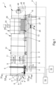
- the plant 1 comprises at least one basic frame 2 positionable resting on a supporting surface P.
- the supporting surface P is substantially horizontal and, preferably, coincides with the ground.
- the plant 1 comprises at least one work chamber 3 associated with the basic frame 2, movable in rotation around a relevant axis A and configured to receive and treat the white slag S resulting from steelmaking processes by means of a withering process.
- the term "withering process” is meant the controlled cooling of the white slag, preferably in a confined atmosphere to avoid the chemical degradation thereof, which leads to a change in the volume of the crystal lattice of one of its main components, di-calcium silicate, with consequent fragmentation and pulverization of the material.
- the resulting lime-rich powder is enhanced by its use in a new steelmaking process (recycling of the material inside the same production cycle) or for other applications.
- the work chamber 3 has an elongated conformation and the axis A substantially coincides with the longitudinal axis of the work chamber itself.
- the plant 1 further comprises movement means 4 of the work chamber 3 adapted to set the work chamber itself in rotation.
- the movement means 4 comprise:
- the movement means 4 are of a different type and that the rotation of the work chamber 3 is carried out in another way.
- the white slag S is moved forward along at least one direction of treatment D.
- the rotation of the work chamber 3 determines the forward movement of the white slag S.
- the direction of treatment D is substantially parallel to the axis A.
- the work chamber 3 comprises:
- the white slag S is moved along the direction of treatment D in succession through the aforementioned portions 8,10,13.
- the work chamber 3 is inclined with respect to the horizon, with the loading portion 8 positioned at a higher level than the sorting and separation portion 13.
- the sorting and separation portion 13 is closer to the supporting surface P with respect to the loading portion 8.
- the plant 1 is also provided with inclination adjustment means 14,15 for adjusting the inclination which are associated with the basic frame 2.
- the adjustment means 14,15 are adapted to allow simple and easy variation of the inclination of the work chamber 3.
- the adjustment means 14,15 thus allow adjusting the residence time of the white slag S to be treated in the plant to the final temperature of the white slag S at the outlet.
- the adjustment means 14,15 comprise a hinging member 14 arranged in the proximity of one of either the loading portion 8 or the sorting and separation portion 13 and a movement device 15, of the type of, e.g., a jack arranged in the proximity of the other of either the loading portion 8 or the sorting and separation portion 13.
- the plant 1 comprises at least one control and command unit 52 operatively connected to at least one of either the movement means 4 or the adjustment means 14,15 and configured to control the operation thereof.
- control and command unit 52 is operatively connected also to the slag feeding system, so as to reduce or increase the flow rate of the slag introduced into the plant 1 according to the loading or unloading temperatures to be managed.
- sensor means are provided, adapted to detect the temperature of the recovery powder R and operatively connected to the control and command unit 52, which is configured to adjust at least one of either the movement means 4 or the adjustment means 14,15 according to the temperature detected by the sensor means.
- the sensor means are positioned, e.g., at the point where the sorting and separation portion 13 is located.
- control and command unit 52 is configured to increase the rotational speed of the work chamber 3 by operating on the movement means 4 and/or to vary the inclination of the work chamber itself by operating on the adjustment means 14,15 when the temperature detected by the sensor means exceeds a preset reference value.
- the loading portion 8 has a substantially truncated-cone shape, diverging away from the inlet port 9.
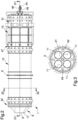
- the cooling portion 10 comprises a plurality of treatment channels 11 which are separate from each other and communicating with the loading portion 8, each of which is adapted to receive a part of the white slag S as a result of the rotation of the work chamber 3, to cool and convey it towards the sorting and separation portion 13.
- such an embodiment allows splitting the white slag S to be treated into a plurality of streams, separate from each other, thus increasing the exchange surface between the white slag S and the cooling means 12, thus optimizing the withering process and reducing the size of the plant 1.
- the cooling means 12 are arranged to at least partly enfold the treatment channels 11 and comprise at least one delivery channel 21, which extends at least through the cooling portion 10 to send the coolant F towards the loading portion 8 counter-currently with respect to the direction of treatment D, and at least one return channel 22, which extends at least through the cooling portion 10 and is arranged to surround the delivery channel 21 to send the coolant F towards the sorting and separation portion 13 in a parallel manner, i.e., equi-currently, to the direction of treatment D.
- One stretch of the return channel 22 is therefore positioned between the delivery channel 21 and the treatment channels 11.
- the return channel 22 therefore surrounds the treatment channels 11.
- the cooling means 12 comprise, then, at least one inlet manifold 42 arranged at the point where the loading portion 8 is located and adapted to transfer the coolant F from the delivery channel 21 to the return channel 22.
- the inlet manifold 42 is positioned between the loading portion 8 and the cooling portion 10.
- the delivery channel 21 and the return channel 22 are contained inside the work chamber 3.
- the cooling means 12 and the treatment channels 11 rotate integrally with each other around the axis A.
- the inlet manifold 42 defines at least one transfer chamber 50 of the coolant F communicating with the delivery channel 21 and with the return channel 22 and through which the treatment channels 11 pass.
- the loading portion 8 is arranged opposite the cooling portion 10 with respect to the inlet manifold 42 and defines at least one interspace 51 communicating with the transfer chamber 50.
- the interspace 51 comprises at least one inlet gap 51a of the coolant F communicating with the transfer chamber 50 and at least one outlet gap 51b of the coolant F communicating with the return channel 22.
- the interspace 51 is therefore adapted to receive the coolant F coming from the delivery channel 21, so as to cool the slag S that is introduced therein, and then conveys the coolant itself inside the return channel 22.
- the cooling means 12 comprise at least one internally hollow cooling liner 18; the delivery channel 21 and the return channel 22 are arranged inside the cooling liner 18.
- the return channel 22 is positioned between the cooling liner 18 and the delivery channel 21 and the treatment channels 11 are inserted inside the return channel 22.
- the cooling means 12 also comprise an outlet manifold 47, communicating with the return channel 22, which is adapted to collect the coolant F passing through the return channel itself and to convey it outwards.
- the delivery channel 21 passes through the outlet manifold 47, exiting outside the work chamber 3.
- the outlet manifold 47 is positioned between the cooling portion 10 and the sorting and separation portion 13.
- both the delivery channel 21 and the return channel 22 exit outside the work chamber 3 by means of the relevant piping at the point where the outlet manifold 47 is located.
- the plant 1 comprises supply means 44 of the coolant F communicating with the delivery channel 21 and discharge means 45 of the coolant F communicating with the return channel 22, where the supply means 44 and the discharge means 45 are arranged outside the work chamber 3.
- the supply means 44 comprise at least one fixed supply duct and the discharge means 45 comprise at least one fixed discharge duct, which are arranged downstream of the sorting and separation portion 13 and are connected, respectively, to the delivery channel 21 and to the return channel 22 by means of a rotary joint 46.
- the control and command unit 52 is operatively connected also to the supply means 44 and is configured to operate thereon, so as to vary the flow rate of the coolant F, depending on the temperature detected by the sensor means.
- control and command unit 52 is configured to increase the flow rate of the coolant F when the temperature of the recovery powder R detected by the sensor means exceeds a preset reference value.
- the treatment channels 11 are substantially parallel to each other.
- the dimensions of the treatment channels 11 are such that even coarse pieces can pass through.
- treatment channels 11 are arranged in a radial pattern with respect to the axis A and each of them comprises a supply port 16 communicating with the loading portion 8.
- the treatment channels 11 have a substantially cylindrical shape.
- the treatment channels 11 may have a shape of different geometry.
- the white slag S is distributed into the treatment channels 11 by gravity, as a result of the rotation of the work chamber 3.
- each supply port 16 in turn, to be at the point where an accumulation is located of the white slag S being loaded into the loading portion 8, allowing it to be automatically split.
- the loading portion 8 is conveniently provided with a plurality of conveying elements 17 adapted to direct the white slag S towards the treatment channels 11.
- the conveying elements 17, of the type of, e.g., helical fins, are internally associated with the loading portion 8 and extend between the inlet port 9 and the supply ports 16.
- the white slag S is subjected to a continuous and controlled cooling process that causes the fragmentation thereof so as to obtain the recovery powder R.
- Cooling is carried out indirectly through the walls of the treatment channels 11, by means of the coolant F flowing inside the return channel 22 located around the treatment channels 11.
- the plant 1 allows dividing the white slag S into several separate streams and cooling them down, by means of a considerably increased exchange surface, with the external dimensions being equal, so that even large quantities of white slag S can be treated, thus ensuring at the same time effective cooling, while keeping the dimensions of the plant 1 considerably reduced.
- the white slag S continuously contacts, by moving forward and mixing, the areas of the treatment channel 11 which are cooled by the coolant F.
- the rotational speed of the work chamber 3 defines the transit speed of the white slag S inside both the cooling portion 10 and the sorting portion 13, thereby establishing the plant flow rate.
- each of the treatment channels 11 comprises a plurality of mixing elements 23 which extend along the direction of treatment D, and which are adapted to mix the white slag S and to convey it towards the sorting and separation portion 13.
- the mixing elements 23, configured e.g. as fin segments, are preferably arranged axially on the inner wall of each treatment channel 11.
- the mixing elements 23 may extend in a continuous or semi-continuous spiral pattern on the inner wall of each treatment channel 11 along the respective direction of treatment D.
- the mixing elements 23 contribute to the forward movement of the stream of white slag S along the direction of treatment D.
- the plant 1 may also comprise inertization means, not shown in detail in the figures, associated with the work chamber 3 and adapted to generate a controlled atmosphere inside at least the cooling portion 10.
- the withering process takes place in an atmosphere with a reduced content of humidity and carbon dioxide, in order to avoid possible processes of hydration, carbonation and, therefore, the degradation of the withered white slag S.
- Each of the treatment channels 11 comprises an outlet port 24, opposite the inlet port 9 and communicating with the sorting and separation portion 13.
- the sorting and separation portion 13 is adjacent and integral with the cooling portion 10.
- the recovery powder R that is generated by the withering process of the white slag S exits the treatment channels 11 through the respective outlet ports 24 and flows out, by discharging it into the sorting and separation portion 13.
- the sorting and separation portion 13 comprises a plurality of holes 25, each provided with at least a predefined size, adapted to allow the outflow of the recovery powder R.
- the plant 1 also comprises collection means 26 of the recovery powder R arranged below the sorting and separation portion 13.
- the recovery powder R falls by gravity from the sorting and separation portion 13 to the collection means 26.
- the collection means 26 comprise at least one collection member 27, of the type, e.g., of a hopper, adapted to convey the recovery powder towards other recovery stations.
- this collection hopper for the recovery powder there is a damper, not visible in detail in the figures, which can be operated manually to allow the powder to be discharged.
- the plant 1 is further provided with a powder containment system 28 associated with the work chamber 3 and arranged to surround at least the sorting and separation portion 13.
- the containment system 28 comprises a powder containment chamber 29 adapted to house the sorting and separation portion 13 and part of the collection member 27.
- the function of the powder containment chamber 29 is to prevent the recovery powder R from being dispersed into the external environment, and it is provided with rotary seals on the outside.
- the containment system 28 also comprises a suction device 30 associated with the powder containment chamber 29.
- the products that maintain a greater size than the predefined size at the end of the withering process form a waste product of the treatment process, basically consisting of a metal-slag mixture.
- the work chamber 3 comprises at least one unloading portion 31 arranged downstream of the sorting and separation portion 13 with respect to the direction of treatment D and adapted to allow the unloading of the waste product resulting from the withering process.
- this unloading portion 31 there is a damper, not shown in detail in the figures, which is manually operable to allow unloading the waste product.
- the waste product exits the work chamber 3 and is conveyed to further disposal or recovery stations.
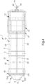
- the plant 1 comprises a plurality of modular elements 32 that can be assembled together to define at least said cooling portion 10.
- This embodiment makes it possible to modify and adapt the plant 1 on the basis of the amount of white slag S to be treated in a simple and easy manner, simply by implementing or reducing the number of modular elements.
- each modular element 32 comprises at least one central member 33 that partly defines the work chamber 3 and a pair of lateral faces 34 opposite each other, each adapted to contact a lateral face 34 of an adjacent modular element 32.
- the central member 33 has a substantially cylindrical shape and extends along the axis A, while the lateral faces 34 have a substantially circular shape and are substantially perpendicular to the axis A.
- the plant 1 comprises connecting means 35 of the modular elements 32 adapted to connect and keep the modular elements themselves joined together.
- the connecting means 35 are, e.g., perforated flanges associated with the outer wall of each modular element 32.
- connecting means 35 are associated with the lateral faces 34 of the modular element 32.
- the plant 1 also comprises sealing means 36, of the type e.g. of circular gaskets, positioned between the modular elements 32 and adapted to operate in conjunction with the connecting means 35 to hermetically connect the modular elements 32.
- sealing means 36 of the type e.g. of circular gaskets
- the modular elements 32 comprise at least cooling modules 37 that can be assembled together to define the cooling portion 10.
- the cooling modules 37 are, therefore, adapted to define the treatment channels 11 and the cooling liner 18.
- Each cooling module 37 also defines a relevant portion of the delivery channel 21 and of the return channel 22 adapted to contain the coolant F.
- each of the lateral faces 34 of the cooling modules 37 comprises a closing plate 38 provided with:
- the cooling modules 37 are, therefore, assembled in succession with each other to form the cooling portion 10 based on the required plant capacity.
- the sorting and separating portion 13 must also be suitably sized in order to allow for an effective screening of the recovery powder R.
- the modular elements 32 also comprise sorting modules 41 that can be assembled together to define the sorting and separation portion 13.
- the central member 33 of the sorting modules 41 is provided with the holes 25 and the lateral faces 34 are open to allow the passage of the recovery powder R and of the waste product.
- the collection means 26 and the containment system 28 are conveniently made to match the size of the sorting and separation portion 13.
- the modular elements 32 also comprise the inlet manifold 42, which connects the loading portion 8 to a subsequent cooling module 37, and the outlet manifold 47, which connects the last of the cooling modules 37 to the first sorting module 41.
- the inlet manifold 42 and the outlet manifold 47 define the cooling portion 10, by limiting it, with the cooling modules 37.
- the lateral face 34 of the inlet manifold 42 communicating with the loading portion 8 comprises a closing plate 38 provided only with the plurality of first openings 39 for the passage of the white slag S, corresponding to the number of treatment channels 11 and defining the supply ports 16.
- the opposite lateral face 34 is similar to the cooling module 37.
- both lateral faces 34 are similar to those of the cooling module 37, shown in Figure 10 .
- the first openings 39 allow the transfer of the recovery powder R and of the waste product inside the sorting modules 41, while the third openings 43 are connectable to respective rotating discharge ducts to allow the discharge of the coolant F.
- the operation of the plant 1 is as follows.
- the supply is provided of the white slag S resulting from the steelmaking processes as well as the loading of the white slag S inside at least one treatment and recovery plant 1.
- loading occurs inside the loading portion 8.
- Loading can be done by means known to the technician skilled in the art such as, e.g., an auger, a conveyor belt, an extractor, or other similar systems, which take the material, e.g., from a collection hopper, where the slag S still hot is initially stored.
- the white slag S is then made to move forward along at least one direction of treatment D so as to generate at least one stream of white slag S and controlled cooling of the stream of white slag S so as to obtain a recovery powder R.
- the loading comprises a stage of splitting the white slag S along a plurality of mutually separate streams of white slag S.
- Cooling is carried out on each of the streams of white slag S using a heat exchange system of the indirect type.
- the movement and cooling stages are carried out inside the cooling portion 10 thanks to the presence of the plurality of treatment channels 11.
- the splitting into multiple streams of white slag S occurs due to the rotation of the work chamber 3 during which the white slag S cyclically flows into one of the treatment channels 11.
- the coolant F transiting inside the return channel 22 arranged externally to the treatment channels themselves allows for a controlled cooling of the slag leading to the formation of the recovery powder R.
- the coolant F is conveyed to the inlet manifold 42 by means of the delivery channel 21, which is centrally arranged inside the work chamber 3, and through the manifold itself it is conveyed along the return channel 22.
- This stage takes place inside the sorting and separation portion 13 and by means of the collection means 26, the recovery powder R is collected and conveyed to any and further treatment and recovery stations.
- the presence of a plurality of treatment channels allows splitting the white slag into several separate streams leading to an increase in the exchange surface between the white slag and the coolant.
- the coolant supply system allows optimizing the compromise between energy efficiency and constructive simplicity.
- the presence of a plurality of treatment channels allows the efficient and easy treatment of even large quantities of white slag.
Landscapes
- Engineering & Computer Science (AREA)
- Mechanical Engineering (AREA)
- Chemical & Material Sciences (AREA)
- General Engineering & Computer Science (AREA)
- Metallurgy (AREA)
- Thermal Sciences (AREA)
- Organic Chemistry (AREA)
- Physics & Mathematics (AREA)
- Materials Engineering (AREA)
- Manufacturing & Machinery (AREA)
- Geology (AREA)
- Life Sciences & Earth Sciences (AREA)
- General Life Sciences & Earth Sciences (AREA)
- Environmental & Geological Engineering (AREA)
- Furnace Details (AREA)
- Carbon Steel Or Casting Steel Manufacturing (AREA)
- Manufacture Of Iron (AREA)
- Curing Cements, Concrete, And Artificial Stone (AREA)
- Processing Of Solid Wastes (AREA)
Applications Claiming Priority (2)
| Application Number | Priority Date | Filing Date | Title |
|---|---|---|---|
| IT102020000007093A IT202000007093A1 (it) | 2020-04-03 | 2020-04-03 | Impianto e procedimento per il trattamento e recupero di scoria bianca risultante da processi siderurgici |
| PCT/IB2021/052745 WO2021198977A1 (en) | 2020-04-03 | 2021-04-01 | Plant for the treatment and recovery of white slag resulting from steelmaking processes |
Publications (3)
| Publication Number | Publication Date |
|---|---|
| EP4127587A1 EP4127587A1 (en) | 2023-02-08 |
| EP4127587B1 true EP4127587B1 (en) | 2025-03-19 |
| EP4127587C0 EP4127587C0 (en) | 2025-03-19 |
Family
ID=70978483
Family Applications (1)
| Application Number | Title | Priority Date | Filing Date |
|---|---|---|---|
| EP21719717.7A Active EP4127587B1 (en) | 2020-04-03 | 2021-04-01 | Plant for the treatment and recovery of white slag resulting from steelmaking processes |
Country Status (8)
| Country | Link |
|---|---|
| US (1) | US20230151446A1 (pl) |
| EP (1) | EP4127587B1 (pl) |
| CN (1) | CN115461589A (pl) |
| BR (1) | BR112022020016A2 (pl) |
| ES (1) | ES3033033T3 (pl) |
| IT (1) | IT202000007093A1 (pl) |
| PL (1) | PL4127587T3 (pl) |
| WO (1) | WO2021198977A1 (pl) |
Families Citing this family (2)
| Publication number | Priority date | Publication date | Assignee | Title |
|---|---|---|---|---|
| KR20240032741A (ko) * | 2021-05-18 | 2024-03-12 | 트루요인스 에스.알.엘. | 개선된 냉각 장치 |
| CN115789673A (zh) * | 2022-11-28 | 2023-03-14 | 江苏荣达电力设备有限公司 | 一种具有防喷灰功能的滚筒式冷渣机 |
Family Cites Families (11)
| Publication number | Priority date | Publication date | Assignee | Title |
|---|---|---|---|---|
| US1769412A (en) * | 1928-06-09 | 1930-07-01 | Traylor Engineering & Mfg Co | Rotary tube cooler |
| JPS5213493A (en) | 1975-07-23 | 1977-02-01 | Nippon Steel Corp | Apparatus for treating molten slag |
| JPS5217388A (en) | 1975-07-31 | 1977-02-09 | Nippon Steel Corp | Treating apparatus of fused slag |
| ITMI20050538A1 (it) | 2005-04-01 | 2006-10-02 | Techint Spa | Metodo e apparato per il recupero della scoria di metallurgia secondaria -lf-e suo riciclo nel processo produttivo di acciaio tramite forno ad arco elettrico |
| CN1944685A (zh) * | 2006-11-14 | 2007-04-11 | 青岛德施普电力设备有限公司 | 叠腔式冷渣机 |
| CN101323892B (zh) * | 2008-07-31 | 2010-06-09 | 东北大学 | 一种底阳极侧导电直流钢包炉 |
| ES2692196T3 (es) | 2009-06-12 | 2018-11-30 | Ferriere Nord S.P.A. | Método, instalación y tambor giratorio para el tratamiento de escoria de caldero de colada |
| ITVE20100055A1 (it) * | 2010-10-21 | 2012-04-22 | Sv Impianti S R L | Processo ed impianto per il recupero e la valorizzazione della scoria da siviera (scoria bianca) prodotta nella fabbricazione dell'acciaio liquido. |
| EP3247811B1 (en) | 2015-01-21 | 2019-06-19 | Material Handling Technology S.p.A. | Plant for recycling of white slag generated during a steel production step |
| IT201600116956A1 (it) | 2016-11-18 | 2018-05-18 | Steb S R L | Sistema e metodo di raffreddamento e recupero della scoria bianca usata nei processi siderurgici |
| WO2020058874A1 (en) * | 2018-09-18 | 2020-03-26 | Material Handling System Industry S.R.L. | Plant for the recovery of white slag resulting from an iron and steel process |
-
2020
- 2020-04-03 IT IT102020000007093A patent/IT202000007093A1/it unknown
-
2021
- 2021-04-01 CN CN202180027490.2A patent/CN115461589A/zh active Pending
- 2021-04-01 PL PL21719717.7T patent/PL4127587T3/pl unknown
- 2021-04-01 BR BR112022020016A patent/BR112022020016A2/pt not_active Application Discontinuation
- 2021-04-01 ES ES21719717T patent/ES3033033T3/es active Active
- 2021-04-01 US US17/916,593 patent/US20230151446A1/en active Pending
- 2021-04-01 WO PCT/IB2021/052745 patent/WO2021198977A1/en not_active Ceased
- 2021-04-01 EP EP21719717.7A patent/EP4127587B1/en active Active
Also Published As
| Publication number | Publication date |
|---|---|
| US20230151446A1 (en) | 2023-05-18 |
| WO2021198977A1 (en) | 2021-10-07 |
| PL4127587T3 (pl) | 2025-07-14 |
| ES3033033T3 (en) | 2025-07-30 |
| EP4127587A1 (en) | 2023-02-08 |
| IT202000007093A1 (it) | 2021-10-03 |
| EP4127587C0 (en) | 2025-03-19 |
| CN115461589A (zh) | 2022-12-09 |
| BR112022020016A2 (pt) | 2022-11-22 |
Similar Documents
| Publication | Publication Date | Title |
|---|---|---|
| EP4127587B1 (en) | Plant for the treatment and recovery of white slag resulting from steelmaking processes | |
| EP3247811B1 (en) | Plant for recycling of white slag generated during a steel production step | |
| RU2441752C2 (ru) | Способ и устройство для обработки полимерного материала | |
| ES2199608T3 (es) | Procedimiento y dispositivo para preparar una mezcla de sustancias que contienen componentes organicos. | |
| EP3323898B2 (en) | System, drum and method for cooling and recycling white slag used in a steel production process description | |
| RU2762953C2 (ru) | Охлаждение сыпучего материала | |
| US4400218A (en) | Apparatus for the continuous manufacture of glucose containing products | |
| EA038076B1 (ru) | Сушильный бункер, а также размольно-сушильный комплекс, включающий в себя такой бункер | |
| CN102465188B (zh) | 罐式冶金熔渣处理装置 | |
| RU2842501C1 (ru) | Установка для обработки и восстановления белого шлака, образующегося в результате сталеплавильных процессов | |
| US4767462A (en) | Method and apparatus for cooling and for further treatment of hot white cement clinker | |
| US4909821A (en) | Apparatus for granulating metallurgical melt | |
| MXPA05000620A (es) | Procedimiento para quemar material combustible mineral granulado. | |
| CN110678711B (zh) | 松散材料的冷却 | |
| WO2020058874A1 (en) | Plant for the recovery of white slag resulting from an iron and steel process | |
| EP4301881B1 (en) | An improved method for the treatment of the black slag | |
| KR100761965B1 (ko) | 슬러지 처리시스템 | |
| CN1199778A (zh) | 冶金熔渣粒化装置 | |
| CN117383771B (zh) | 一种连续式油泥包预处理系统及工艺 | |
| US3148864A (en) | Pneumatic conveying and reclaiming method and apparatus | |
| CN116656891B (zh) | 一种钢渣改性及分粒径处理的f-CaO消解装置和方法 | |
| CN105819653A (zh) | 污泥干化的控制系统 | |
| CN117185260B (zh) | 一种硫磺液下造粒系统和硫磺液下造粒方法 | |
| CN218222322U (zh) | 一种基于dcs控制的粒料系统 | |
| AU739439B3 (en) | Granulation of blast furnace slag |
Legal Events
| Date | Code | Title | Description |
|---|---|---|---|
| STAA | Information on the status of an ep patent application or granted ep patent |
Free format text: STATUS: UNKNOWN |
|
| STAA | Information on the status of an ep patent application or granted ep patent |
Free format text: STATUS: THE INTERNATIONAL PUBLICATION HAS BEEN MADE |
|
| PUAI | Public reference made under article 153(3) epc to a published international application that has entered the european phase |
Free format text: ORIGINAL CODE: 0009012 |
|
| STAA | Information on the status of an ep patent application or granted ep patent |
Free format text: STATUS: REQUEST FOR EXAMINATION WAS MADE |
|
| 17P | Request for examination filed |
Effective date: 20221024 |
|
| AK | Designated contracting states |
Kind code of ref document: A1 Designated state(s): AL AT BE BG CH CY CZ DE DK EE ES FI FR GB GR HR HU IE IS IT LI LT LU LV MC MK MT NL NO PL PT RO RS SE SI SK SM TR |
|
| DAV | Request for validation of the european patent (deleted) | ||
| DAX | Request for extension of the european patent (deleted) | ||
| RIC1 | Information provided on ipc code assigned before grant |
Ipc: F27D 21/00 20060101ALI20240123BHEP Ipc: F28D 7/16 20060101ALI20240123BHEP Ipc: F27B 7/38 20060101ALI20240123BHEP Ipc: C21B 3/08 20060101ALI20240123BHEP Ipc: F28F 5/02 20060101ALI20240123BHEP Ipc: F28D 11/04 20060101ALI20240123BHEP Ipc: C22B 7/04 20060101ALI20240123BHEP Ipc: F27D 9/00 20060101AFI20240123BHEP |
|
| GRAP | Despatch of communication of intention to grant a patent |
Free format text: ORIGINAL CODE: EPIDOSNIGR1 |
|
| STAA | Information on the status of an ep patent application or granted ep patent |
Free format text: STATUS: GRANT OF PATENT IS INTENDED |
|
| GRAJ | Information related to disapproval of communication of intention to grant by the applicant or resumption of examination proceedings by the epo deleted |
Free format text: ORIGINAL CODE: EPIDOSDIGR1 |
|
| STAA | Information on the status of an ep patent application or granted ep patent |
Free format text: STATUS: REQUEST FOR EXAMINATION WAS MADE |
|
| INTG | Intention to grant announced |
Effective date: 20240304 |
|
| INTC | Intention to grant announced (deleted) | ||
| GRAP | Despatch of communication of intention to grant a patent |
Free format text: ORIGINAL CODE: EPIDOSNIGR1 |
|
| STAA | Information on the status of an ep patent application or granted ep patent |
Free format text: STATUS: GRANT OF PATENT IS INTENDED |
|
| INTG | Intention to grant announced |
Effective date: 20240521 |
|
| GRAS | Grant fee paid |
Free format text: ORIGINAL CODE: EPIDOSNIGR3 |
|
| GRAA | (expected) grant |
Free format text: ORIGINAL CODE: 0009210 |
|
| STAA | Information on the status of an ep patent application or granted ep patent |
Free format text: STATUS: THE PATENT HAS BEEN GRANTED |
|
| AK | Designated contracting states |
Kind code of ref document: B1 Designated state(s): AL AT BE BG CH CY CZ DE DK EE ES FI FR GB GR HR HU IE IS IT LI LT LU LV MC MK MT NL NO PL PT RO RS SE SI SK SM TR |
|
| REG | Reference to a national code |
Ref country code: GB Ref legal event code: FG4D |
|
| REG | Reference to a national code |
Ref country code: CH Ref legal event code: EP |
|
| REG | Reference to a national code |
Ref country code: DE Ref legal event code: R096 Ref document number: 602021027799 Country of ref document: DE |
|
| REG | Reference to a national code |
Ref country code: IE Ref legal event code: FG4D |
|
| U01 | Request for unitary effect filed |
Effective date: 20250416 |
|
| U07 | Unitary effect registered |
Designated state(s): AT BE BG DE DK EE FI FR IT LT LU LV MT NL PT RO SE SI Effective date: 20250424 |
|
| U20 | Renewal fee for the european patent with unitary effect paid |
Year of fee payment: 5 Effective date: 20250416 |
|
| PG25 | Lapsed in a contracting state [announced via postgrant information from national office to epo] |
Ref country code: RS Free format text: LAPSE BECAUSE OF FAILURE TO SUBMIT A TRANSLATION OF THE DESCRIPTION OR TO PAY THE FEE WITHIN THE PRESCRIBED TIME-LIMIT Effective date: 20250619 |
|
| PGFP | Annual fee paid to national office [announced via postgrant information from national office to epo] |
Ref country code: PL Payment date: 20250612 Year of fee payment: 5 |
|
| PGFP | Annual fee paid to national office [announced via postgrant information from national office to epo] |
Ref country code: ES Payment date: 20250617 Year of fee payment: 5 |
|
| PG25 | Lapsed in a contracting state [announced via postgrant information from national office to epo] |
Ref country code: NO Free format text: LAPSE BECAUSE OF FAILURE TO SUBMIT A TRANSLATION OF THE DESCRIPTION OR TO PAY THE FEE WITHIN THE PRESCRIBED TIME-LIMIT Effective date: 20250619 |
|
| PG25 | Lapsed in a contracting state [announced via postgrant information from national office to epo] |
Ref country code: HR Free format text: LAPSE BECAUSE OF FAILURE TO SUBMIT A TRANSLATION OF THE DESCRIPTION OR TO PAY THE FEE WITHIN THE PRESCRIBED TIME-LIMIT Effective date: 20250319 |
|
| PG25 | Lapsed in a contracting state [announced via postgrant information from national office to epo] |
Ref country code: GR Free format text: LAPSE BECAUSE OF FAILURE TO SUBMIT A TRANSLATION OF THE DESCRIPTION OR TO PAY THE FEE WITHIN THE PRESCRIBED TIME-LIMIT Effective date: 20250620 |
|
| REG | Reference to a national code |
Ref country code: ES Ref legal event code: FG2A Ref document number: 3033033 Country of ref document: ES Kind code of ref document: T3 Effective date: 20250730 |
|
| PG25 | Lapsed in a contracting state [announced via postgrant information from national office to epo] |
Ref country code: SM Free format text: LAPSE BECAUSE OF FAILURE TO SUBMIT A TRANSLATION OF THE DESCRIPTION OR TO PAY THE FEE WITHIN THE PRESCRIBED TIME-LIMIT Effective date: 20250319 |
|
| PG25 | Lapsed in a contracting state [announced via postgrant information from national office to epo] |
Ref country code: CZ Free format text: LAPSE BECAUSE OF FAILURE TO SUBMIT A TRANSLATION OF THE DESCRIPTION OR TO PAY THE FEE WITHIN THE PRESCRIBED TIME-LIMIT Effective date: 20250319 |
|
| PG25 | Lapsed in a contracting state [announced via postgrant information from national office to epo] |
Ref country code: SK Free format text: LAPSE BECAUSE OF FAILURE TO SUBMIT A TRANSLATION OF THE DESCRIPTION OR TO PAY THE FEE WITHIN THE PRESCRIBED TIME-LIMIT Effective date: 20250319 |
|
| PG25 | Lapsed in a contracting state [announced via postgrant information from national office to epo] |
Ref country code: IS Free format text: LAPSE BECAUSE OF FAILURE TO SUBMIT A TRANSLATION OF THE DESCRIPTION OR TO PAY THE FEE WITHIN THE PRESCRIBED TIME-LIMIT Effective date: 20250719 |
|
| REG | Reference to a national code |
Ref country code: CH Ref legal event code: H13 Free format text: ST27 STATUS EVENT CODE: U-0-0-H10-H13 (AS PROVIDED BY THE NATIONAL OFFICE) Effective date: 20251125 |
|
| PG25 | Lapsed in a contracting state [announced via postgrant information from national office to epo] |
Ref country code: MC Free format text: LAPSE BECAUSE OF FAILURE TO SUBMIT A TRANSLATION OF THE DESCRIPTION OR TO PAY THE FEE WITHIN THE PRESCRIBED TIME-LIMIT Effective date: 20250319 |
|
| PG25 | Lapsed in a contracting state [announced via postgrant information from national office to epo] |
Ref country code: CH Free format text: LAPSE BECAUSE OF NON-PAYMENT OF DUE FEES Effective date: 20250430 |
|
| PLBE | No opposition filed within time limit |
Free format text: ORIGINAL CODE: 0009261 |
|
| STAA | Information on the status of an ep patent application or granted ep patent |
Free format text: STATUS: NO OPPOSITION FILED WITHIN TIME LIMIT |
|
| REG | Reference to a national code |
Ref country code: CH Ref legal event code: L10 Free format text: ST27 STATUS EVENT CODE: U-0-0-L10-L00 (AS PROVIDED BY THE NATIONAL OFFICE) Effective date: 20260128 |
|
| 26N | No opposition filed |
Effective date: 20251222 |
|
| GBPC | Gb: european patent ceased through non-payment of renewal fee |
Effective date: 20250619 |
|
| PG25 | Lapsed in a contracting state [announced via postgrant information from national office to epo] |
Ref country code: GB Free format text: LAPSE BECAUSE OF NON-PAYMENT OF DUE FEES Effective date: 20250619 |
|
| PG25 | Lapsed in a contracting state [announced via postgrant information from national office to epo] |
Ref country code: IE Free format text: LAPSE BECAUSE OF NON-PAYMENT OF DUE FEES Effective date: 20250401 |
|
| PGFP | Annual fee paid to national office [announced via postgrant information from national office to epo] |
Ref country code: TR Payment date: 20260325 Year of fee payment: 6 |