EP4127463B1 - Energieübertragung in einer windkraftanlage - Google Patents
Energieübertragung in einer windkraftanlage Download PDFInfo
- Publication number
- EP4127463B1 EP4127463B1 EP21721860.1A EP21721860A EP4127463B1 EP 4127463 B1 EP4127463 B1 EP 4127463B1 EP 21721860 A EP21721860 A EP 21721860A EP 4127463 B1 EP4127463 B1 EP 4127463B1
- Authority
- EP
- European Patent Office
- Prior art keywords
- wind turbine
- tower
- voltage
- generator
- transformer
- Prior art date
- Legal status (The legal status is an assumption and is not a legal conclusion. Google has not performed a legal analysis and makes no representation as to the accuracy of the status listed.)
- Active
Links
Images


Classifications
-
- F—MECHANICAL ENGINEERING; LIGHTING; HEATING; WEAPONS; BLASTING
- F03—MACHINES OR ENGINES FOR LIQUIDS; WIND, SPRING, OR WEIGHT MOTORS; PRODUCING MECHANICAL POWER OR A REACTIVE PROPULSIVE THRUST, NOT OTHERWISE PROVIDED FOR
- F03D—WIND MOTORS
- F03D80/00—Details, components or accessories not provided for in groups F03D1/00 - F03D17/00
- F03D80/80—Arrangement of components within nacelles or towers
- F03D80/82—Arrangement of components within nacelles or towers of electrical components
-
- F—MECHANICAL ENGINEERING; LIGHTING; HEATING; WEAPONS; BLASTING
- F03—MACHINES OR ENGINES FOR LIQUIDS; WIND, SPRING, OR WEIGHT MOTORS; PRODUCING MECHANICAL POWER OR A REACTIVE PROPULSIVE THRUST, NOT OTHERWISE PROVIDED FOR
- F03D—WIND MOTORS
- F03D13/00—Assembly, mounting or commissioning of wind motors; Arrangements specially adapted for transporting wind motor components
- F03D13/20—Arrangements for mounting or supporting wind motors; Masts or towers for wind motors
-
- F—MECHANICAL ENGINEERING; LIGHTING; HEATING; WEAPONS; BLASTING
- F03—MACHINES OR ENGINES FOR LIQUIDS; WIND, SPRING, OR WEIGHT MOTORS; PRODUCING MECHANICAL POWER OR A REACTIVE PROPULSIVE THRUST, NOT OTHERWISE PROVIDED FOR
- F03D—WIND MOTORS
- F03D9/00—Adaptations of wind motors for special use; Combinations of wind motors with apparatus driven thereby; Wind motors specially adapted for installation in particular locations
- F03D9/20—Wind motors characterised by the driven apparatus
- F03D9/25—Wind motors characterised by the driven apparatus the apparatus being an electrical generator
- F03D9/255—Wind motors characterised by the driven apparatus the apparatus being an electrical generator connected to electrical distribution networks; Arrangements therefor
-
- Y—GENERAL TAGGING OF NEW TECHNOLOGICAL DEVELOPMENTS; GENERAL TAGGING OF CROSS-SECTIONAL TECHNOLOGIES SPANNING OVER SEVERAL SECTIONS OF THE IPC; TECHNICAL SUBJECTS COVERED BY FORMER USPC CROSS-REFERENCE ART COLLECTIONS [XRACs] AND DIGESTS
- Y02—TECHNOLOGIES OR APPLICATIONS FOR MITIGATION OR ADAPTATION AGAINST CLIMATE CHANGE
- Y02E—REDUCTION OF GREENHOUSE GAS [GHG] EMISSIONS, RELATED TO ENERGY GENERATION, TRANSMISSION OR DISTRIBUTION
- Y02E10/00—Energy generation through renewable energy sources
- Y02E10/70—Wind energy
- Y02E10/72—Wind turbines with rotation axis in wind direction
-
- Y—GENERAL TAGGING OF NEW TECHNOLOGICAL DEVELOPMENTS; GENERAL TAGGING OF CROSS-SECTIONAL TECHNOLOGIES SPANNING OVER SEVERAL SECTIONS OF THE IPC; TECHNICAL SUBJECTS COVERED BY FORMER USPC CROSS-REFERENCE ART COLLECTIONS [XRACs] AND DIGESTS
- Y02—TECHNOLOGIES OR APPLICATIONS FOR MITIGATION OR ADAPTATION AGAINST CLIMATE CHANGE
- Y02E—REDUCTION OF GREENHOUSE GAS [GHG] EMISSIONS, RELATED TO ENERGY GENERATION, TRANSMISSION OR DISTRIBUTION
- Y02E10/00—Energy generation through renewable energy sources
- Y02E10/70—Wind energy
- Y02E10/728—Onshore wind turbines
Definitions
- the invention relates to a wind turbine, comprising a generator, a transformer, an energy transmission device, a network connection point and a tower structure, wherein the energy transmission device extends from the nacelle to the foot of the wind turbine and electrically connects the generator to the network connection point via the transformer.
- the invention further relates to a method for operating such a wind turbine.
- the electrical energy In wind turbines, the electrical energy must be transported from the generator to the power grid, which is available as a grid connection point at the base of the tower structure. Since the generator is always arranged at the top of the nacelle, an energy transfer device from the nacelle to the bottom of the wind turbine, also referred to as the base of the wind turbine, is required.
- This energy transmission device is usually formed by several cables, which represent an electrical connection for energy transmission with alternating voltage or direct voltage. This connection must be designed for full power, which requires appropriate cable cross-sections. Due to the height of the wind turbines, cable lengths of over 100 m are not uncommon in modern wind turbines.
- the usual working voltage of the generators is in the low voltage range, i.e. below 1000V, and is typically 690V.
- the usual mains voltage for the connection at the mains connection point is a medium voltage of over 1kV and is typically 20kV.
- the path of the energy from the generator to the energy supply network usually takes place via a frequency converter, cables from the nacelle to the base of the wind turbine and a transformer. Transformers and frequency converters can be used be arranged at the top of the nacelle or at the foot of the wind turbine.
- document DE102011003208 A1 shows an example from the prior art.
- the invention is based on the object of improving the energy transfer between the nacelle and the base of the wind turbine.
- a wind turbine comprising a generator, a transformer, an energy transmission device for transmitting electrical energy generated by the generator, a network connection point and a tower structure, the energy transmission device extending from the nacelle to the foot of the wind turbine and the Generator electrically connects via the transformer to the grid connection point, the energy transmission device comprising a metal structure of the tower structure as a first conductor, the metal structure being designed at least in sections as an electrically conductive connection from the nacelle to the foot of the wind turbine, the transformer being at the foot of the wind turbine is arranged, wherein the transformer connects the energy transmission device and the network connection point to one another in an electrically conductive and galvanically isolated manner, the metal structure being electrically conductively connected to a predetermined reference potential, in particular to the earth potential.
- this object is achieved by a method for operating such a wind turbine, according to claim 7, wherein a current for transmitting electrical energy generated by the generator from the nacelle to the foot of the wind turbine is passed at least in sections and or partially through the metal structure of the tower structure.
- the invention is based on the knowledge that this reduces the amount of electrical conductors, such as busbars and/or cables, from the nacelle to the base of the wind turbine can be significantly reduced by the fact that the current is routed at least in sections and / or partially via a metal structure of the tower structure.
- the metal structure of the tower is used for energy transmission, ie for conducting the current.
- the energy transmission device is intended to transmit the electrical power generated by the generator to the grid connection point.
- the metal of the metal structure is a good electrical conductor. It is used in different forms for the tower structure and its construction. For example, metal is used in the form of a steel lattice tower. In the steel lattice tower, almost the entire tower is a lattice structure made of steel, a material that contains iron as a metal. This metal, for example in iron or steel, can be easily used to conduct electricity. It represents a good electrical conductor with an electrical conductivity of typically more than 10 6 S/m. In other words, the metal structure of the steel lattice tower with an electrical conductivity of more than 10 6 S/m for both the structural and mechanical properties as well as at the same time particularly advantageously suitable for the energy transmission device in order to transmit the energy with little loss.
- reinforcement made of a conductive material such as metal or iron can be used within a concrete tower to conduct electrical current.
- the reinforcement is also a good electrical conductor with an electrical conductivity of typically more than 10 6 S/m.
- the metal construction of the reinforcement of the reinforced concrete tower with an electrical conductivity of more than 10 6 S/m is suitable for both the structural and mechanical properties and at the same time particularly advantageous for the energy transmission device in order to transmit the energy with little loss.
- the current is transmitted via several conductors, which are usually designed as cables. At least three conductors are required for the transmission of electrical energy using a three-phase network, and at least two conductors are required for transmission using a direct voltage.
- the metal construction to conduct current as the first conductor, the use of one or more electrically parallel cables for this conductor can be eliminated.
- it is also possible to reduce the cross section of the cables by using a smaller number of parallel cables and/or cables with a smaller cross section and/or cables with a lower current carrying capacity. In other words, it is possible either to lead the entire current of the first conductor, i.e.
- one of the phases and a DC voltage potential through the metal construction or, alternatively, to transmit at least part of this current through the metal construction, while the remaining portion of the current is transmitted via cables with a smaller cable cross-section and/or lower conductivity can be transported with little loss.
- the entire distance from the gondola to the base can be covered through the metal of the metal structure.
- the current can be routed in sections, ie over one or more sections from the nacelle to the base of the wind turbine, through the metal structure of the tower structure. These sections can then be connected to each other again using a busbar or a cable.
- the length of a reinforcing bar is usually significantly shorter than the entire tower. This is due, for example, to the fact that the entire tower structure is formed by a large number of individual, prefabricated tower elements, also referred to as concrete elements, which are then arranged one above the other to erect the tower.
- a metal connection it is possible to electrically contact the reinforcing bar or the reinforcing grid, preferably inside the concrete casing, using a metal connection.
- the metal of the tower structure is used in sections for the energy transfer in the tower structure.
- cables can be saved or at least dimensioned for significantly lower currents.
- any danger due to the voltage present on the metal structure must be reliably excluded. This can be done, for example, by applying insulation.
- this can also be done by providing protection against contact by means of grounding or ensuring a low contact voltage.
- the transformer which is arranged at the foot of the tower structure, the energy transmission device is galvanically isolated from the network connection point and thus also from the connected energy supply network.
- a reference potential can therefore be freely set for the energy transmission device. This is chosen so that the potential of the metal structure does not exceed a permissible contact voltage. In the case of a direct voltage this is typically 120V, in the case of an alternating voltage of 50Hz or 60Hz this is typically 60V. It has proven to be particularly advantageous to set the potential of the metal construction to the earth potential by connecting the metal construction grounded. This ensures contact protection in a simple manner without the need to monitor a corresponding reference potential. The remaining conductors can then be designed for insulation to match the conductor-conductor voltage.
- the transformer is arranged at the foot of the tower structure for galvanic isolation so that a reference potential for the energy transmission device can be set independently of the reference potential of the energy supply network. If the transformer is arranged at the base of the wind turbine, the construction of the tower structure is significantly simpler, since the high weight of the transformer at the base allows the tower structure to be arranged much more easily than if the transformer were accommodated in the nacelle. This results in the synergetic effect of accommodating the transformer at the foot of the wind turbine that both the high weight of the transformer is arranged particularly favorably at the foot of the wind turbine and at the same time a free choice of the reference potential for the energy transmission device can be specified in order to ensure the safety of the wind turbine ensure.
- the connections of the individual concrete elements can be made with a non-insulated busbar, because contact safety is ensured by specifying the reference potential with a sufficiently low contact voltage, in particular by means of grounding.
- Lifting the transformer into the nacelle during assembly and/or commissioning would be very complex and costly, as the high weight in the nacelle also requires expensive design measures.
- a replacement in the event of a defect is significantly more expensive if it is arranged in the gondola.
- a frequency converter for regulating the energy flow of the wind turbine at the foot of the tower structure. This arrangement facilitates, in addition to simpler construction of the tower structure and easier installation of the frequency converter also the maintenance of the wind turbine.
- the arrangement of the transformer at the base of the tower structure has the disadvantage of a low voltage compared to the mains voltage of the energy supply network and the associated high currents in the energy transmission system.
- This disadvantage manifests itself in larger cable cross-sections for a higher current-carrying capacity of the cables.
- this disadvantage is more than compensated for by conducting the current through the metal construction and the associated savings in cables/busbars.
- a galvanically isolated connection is often referred to as galvanically isolated.
- the metal construction of the tower structure is at least partially formed by a steel lattice tower.
- a steel lattice tower there is an electrically conductive connection from the nacelle to the base of the tower structure, which can be used to conduct a current of a phase of a three-phase voltage system or a potential of a direct voltage.
- no or at least almost no structural changes need to be made to the steel lattice structure.
- the potential of the metal structure to a voltage that is harmless compared to the ground potential, operation is also easy from a safety perspective. It is particularly advantageous to ground the potential of the steel lattice tower and thus ensure contact protection in a particularly simple manner.
- the entire tower can be designed as a steel lattice tower or just parts of it, so that at least in sections the electricity is routed from the gondola to the foot of the tower structure through the metal construction.
- the cross sections of the metal construction used and the good cooling properties through the air of the open design make it possible to allow the entire current of the conductor, ie the first conductor, to flow through the metal construction and to dispense with additional cables or busbars arranged in parallel.
- the entire current path from the nacelle to the foot of the tower structure can also be realized completely and not just in sections in a simple manner using the metal construction, since the entire steel lattice tower with a current conductivity of more than 10 6 S/m represents a well-conducting connection. Even with a current conductivity of the metal structure of the steel lattice tower of only more than 10 3 S/m, economical and low-loss operation is possible due to the large cross-sectional area.
- a particular advantage is that the metal construction not only serves to ensure the mechanical stability of the tower, but also takes on parts of the energy transmission function without making the metal construction more complex.
- the tower structure is at least partially designed as a concrete tower, the metal structure of the tower structure being formed at least in sections by reinforcement or parts of the reinforcement of the concrete tower.
- the reinforcement can be designed, for example, as a reinforcement grid or as reinforcing bars.
- reinforcement is used to achieve the necessary tensile strength. This can also be used to conduct electricity for energy transfer from the nacelle to the base of the tower structure.
- the reinforcement can be used to create a continuous electrical connection from the nacelle to the base of the tower structure, or the reinforcement can be used in sections. For example, within a tower element, the current is conducted through the metal of the concrete structure and then out of the concrete, preferably by means of a connection led out into the interior of the tower. A connection to the next tower element and the reinforcement there is then created there using cables or busbars.
- a concrete tower In contrast to a steel lattice structure, a concrete tower contains several parallel reinforcement strands that are electrically insulated from each other. These can be electrically connected in parallel at different heights of the tower, for example through conductive rings, in particular metal rings, at the transition between concrete elements in order to achieve good conductivity through the reinforcement. This means that the electrical resistance and the associated losses and heating in the concrete are so low that the metal construction can be used to conduct high currents of over 1000A. Since the concrete does not have sufficient insulation properties, setting a suitable reference potential to avoid dangerous contact voltages ensures safe operation of the wind turbine. In the case of a concrete tower, it is particularly advantageous to connect the metal structure to earth potential, as contact protection can be implemented particularly easily and reliably in this way.
- the height of the tower structure is at least 100m.
- the need for efficient energy transfer from the nacelle to the base of the wind turbine is growing. For a wind turbine with a height of over 100m, the proposed arrangement can significantly save costs for cabling, tower construction and assembly.
- the energy transmission device is set up for operation with a voltage in the low-voltage range, in particular with a nominal voltage of 690V.
- the low-voltage range especially with a nominal voltage of 690V, allows the generator to be manufactured cost-effectively in terms of performance, weight and size, among other things.
- the metal construction By using the metal construction, currents generated even at this voltage can be transmitted cost-effectively in terms of required cables and electrical losses within the tower structure, i.e. through the metal construction.
- a third of the cables can be saved in a three-phase system without causing any significant disadvantages.
- this voltage level in the low-voltage range the entire system of the wind turbine with its generator and energy transmission components can be implemented particularly cost-effectively and reliably.
- a rectifier is arranged between the generator and the energy transmission device, an inverter being arranged between the energy transmission device and the transformer, the energy transmission device being set up for operation with a direct voltage, in particular in the voltage range from 800V to 1500V.
- a frequency converter for controlling or regulating the system is arranged in the nacelle and at the foot of the tower structure.
- the rectifier and the inverter are components of the frequency converter.
- rectifier and inverters refer to a direction of energy flow from generator to power grid.
- a rectifier is required to rectify the alternating current into a direct current in the nacelle.
- This rectifier should preferably be a controllable rectifier in order to be able to control or regulate the behavior of the wind turbine.
- the energy is then transferred from the nacelle to the base of the tower structure using a direct voltage.
- the direct voltage transmission requires two conductors, of which the first conductor of these conductors is formed by the metal structure of the tower structure. In this case, half of the cabling can be saved due to the two conductors required, so that this arrangement is particularly cost-effective and economical to operate.
- the rectifier and the generator are as light and small as possible to enable easy installation in the nacelle, operating the energy transmission device with a voltage in the range of 800V to 1500V has proven to be particularly advantageous.
- the structure of the generator is simple for this voltage range, and semiconductors for the rectifier in this voltage range are reliably and inexpensively available on the market. In this case, there is no need for additional controllers to adjust the DC voltage.
- a direct voltage of 1100V has proven to be particularly advantageous in the interaction of all components arranged in the nacelle, as this voltage can be easily generated from a generator with a nominal voltage of 690V. In this case, both the generator and the rectifier can be operated in a working range with high efficiency.
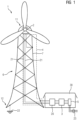
- the FIG 1 shows a wind turbine 1.
- the tower structure 6 of this wind turbine 1 is designed as a steel lattice tower.
- the generator 2 is located in the nacelle 11 of the wind turbine 1.
- the transformer 3, the grid connection point 5 and a frequency converter 20 for regulating the energy flow are arranged at the base 12 of the wind turbine 1. Since the lattice construction of the steel lattice tower is an open construction, it has proven to be advantageous to arrange the components such as the transformer 3, the network connection point 5 and / or the frequency converter 20 at the base 12 in a building 30 protected from the weather.
- the energy is transferred from the nacelle 11 to the base 12 of the wind turbine 1 via the energy transmission device 4.
- This includes three conductors.
- the metal construction 7 of the tower structure 6 forms the first conductor in order to transmit electrical energy with a current through the metal construction 7.
- the remaining two conductors are formed by cables 21 or busbars.
- the metal construction 7 takes over the conduction of the current from the nacelle 11 to the base of the wind turbine 1. In the vicinity of the generator 2, for example with the help of a short cable, an electrical connection of a phase of the generator 2 to the metal construction 7 is created. Likewise, at the base 12 of the wind turbine 1, the electricity is again taken from the metal structure 7 and fed to the frequency converter 20 and/or the transformer 3.
- the potential of the metal construction 7 is advantageously connected to the earth potential by means of a grounding device 22. This means that there is no longer any danger from the circuit and the wind turbine 1, in particular from the energy transmission device 4.
- the electrical energy generated by the wind flows into the energy supply network 23 at the network connection point 5 via the frequency converter 20 and the transformer 3.
- the frequency converter 20 can be connected to the transformer 3 on the generator side or on the energy supply network 23 side.
- the frequency converter 20 is advantageously arranged on the low-voltage side of the transformer 3, since the frequency converter 20 is then cheaper and smaller.
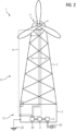
- FIG 2 shows another example of a wind turbine 1.
- This exemplary embodiment is a combination of the tower structure 6 made of a steel lattice tower and a concrete tower.
- the lower part represents a concrete tower in which some components, such as frequency converter 20, transformer 3 and network connection point 5, are housed protected from environmental influences.
- This is then followed by a lattice construction of a steel lattice tower, which is easy and inexpensive to produce.
- the current can be carried through the metal structure 7 of the steel lattice tower and/or through the metal structure 7 of the concrete tower.
- the metal structure 7 of the concrete tower is formed by the reinforcement of the concrete tower.
- the current is transmitted from the lattice structure to the reinforcement of the concrete tower, for example by means of a cable or a busbar, in particular a non-insulated busbar.
- the tower structure 6 is designed as a concrete tower.
- the concrete tower is made up of a large number of concrete elements.
- Each of these concrete elements has a metal structure 7 through the reinforcement, which carries the current of the first conductor.
- a connection for example in the form of a connection, is led out to the metal structure 7 into the interior of the tower structure 6. This means that the metal structures of neighboring concrete elements can be connected to one another, for example using a cable.
- a rectifier 8 is arranged in the nacelle 11 next to the generator 2, which converts the alternating voltage and the alternating current generated by the generator 2 into a direct voltage and a direct current. Therefore, only two conductors are required to transmit electrical energy. By eliminating the cable for the first conductor, since the first conductor is realized by the metal construction 7, approximately half of the cables can be eliminated in this exemplary embodiment.
- the current is transmitted in sections through the metal construction 7 of the individual concrete elements. At the transitions between the concrete elements, a conductor such as a cable or a busbar, in particular a non-insulated busbar, is used to transmit the current. Before the electrical energy is supplied to the transformer 3, it is converted into an alternating voltage or alternating current by means of an inverter 9.
- the concrete construction is particularly suitable for designing the energy transmission device 4 with a direct voltage, since there is a rectifier 8 in the nacelle 11 of the wind turbine 1 is arranged. This arrangement can be done protected by the concrete tower.
- the energy transmission device 4 can also be used Figures 1 and 2 be carried out with the help of a direct voltage if a rectifier 8 is arranged in the nacelle 11 and an inverter 9 is arranged at the base 12 of the wind turbine 1.
- the FIG 4 shows a concrete element 33.
- a tower structure 6 of a concrete tower is realized with a large number of concrete elements 33 stacked on top of one another.
- the reinforcement present in the concrete element 33 is shown in dashed lines because it is arranged inside the concrete.
- the reinforcement is designed as a reinforcement grid 31.
- the reinforcement forms the metal structure 7 of the tower structure 6.
- the current flows in sections in the tower structure 6 through the reinforcement grid 31.
- the connection to the reinforcement grid 31 of the adjacent concrete element 33 can be established via the connections 32 using cables or busbars.
- the connections 32 are conductively connected to the reinforcement.
- the invention relates to a wind turbine, comprising a generator, a transformer, an energy transmission device for transmitting electrical energy generated by the generator, a network connection point and a tower structure, wherein the energy transmission device extends from the nacelle to the base of the wind turbine and electrically connects the generator to the grid connection point via the transformer.
- the energy transmission device comprises a metal structure of the tower structure as a first conductor, the metal structure being designed at least in sections as an electrically conductive connection from the nacelle to the base of the wind turbine, the transformer being arranged at the base of the wind turbine, wherein the transformer connects the energy transmission device and the network connection point to one another in an electrically conductive and galvanically isolated manner, the metal structure being electrically conductively connected to a predetermined reference potential, in particular to the earth potential.
- the invention further relates to a method for operating such a wind turbine, wherein a current for transmitting electrical energy generated by the generator from the nacelle to the base of the wind turbine is passed at least in sections and / or partially through the metal structure of the tower structure.
Landscapes
- Engineering & Computer Science (AREA)
- Life Sciences & Earth Sciences (AREA)
- Sustainable Development (AREA)
- Sustainable Energy (AREA)
- Chemical & Material Sciences (AREA)
- Combustion & Propulsion (AREA)
- Mechanical Engineering (AREA)
- General Engineering & Computer Science (AREA)
- Power Engineering (AREA)
- Wind Motors (AREA)
Description
- Die Erfindung betrifft eine Windkraftanlage, aufweisend einen Generator, einen Transformator, eine Energieübertragungsvorrichtung, einen Netzanschlusspunkt und einen Turmaufbau, wobei sich die Energieübertragungsvorrichtung von der Gondel zum Fuß der Windkraftanlage erstreckt und den Generator elektrisch über den Transformator mit dem Netzanschlusspunkt verbindet. Ferner betrifft die Erfindung ein Verfahren zum Betreiben einer derartigen Windkraftanlage.
- Bei Windkraftanlagen muss die elektrische Energie vom Generator ins Stromnetz transportiert werden, das am Fuß des Turmaufbaus als Netzanschlusspunkt verfügbar ist. Da der Generator immer oben in der Gondel angeordnet ist, ist also eine Energieübertragungsvorrichtung von der Gondel zum Boden der Windkraftanlage, auch als Fuß der Windkraftanlage bezeichnet, erforderlich. Diese Energieübertragungsvorrichtung wird dabei meist durch mehrere Kabel gebildet, welche eine elektrische Verbindung für eine Energieübertragung mit Wechselspannung oder Gleichspannung darstellen. Diese Verbindung muss auf die volle Leistung ausgelegt sein, was entsprechende Kabelquerschnitte nötig macht. Dabei sind Kabellängen von über 100 m aufgrund der Höhe der Windkraftanlagen keine Seltenheit in modernen Windkraftanlagen.
- Die übliche Arbeitsspannung der Generatoren liegt im Bereich der Niederspannung, also unterhalb 1000V, und beträgt typischerweise 690V. Die übliche Netzspannung für die Verbindung am Netzanschlusspunkt ist eine Mittelspannung von über 1kV und beträgt typischerweise 20kV.
- Der Weg der Energie vom Generator in das Energieversorgungsnetz erfolgt üblicherweise über einen Frequenzumrichter, Kabel von der Gondel zum Fuß der Windkraftanlage und einem Transformator. Dabei können Transformator und Frequenzumrichter oben in der Gondel oder am Fuß der Windkraftanlage angeordnet sein. Dokument
DE102011003208 A1 zeigt ein Beispiel aus dem Stand der Technik. - Der Erfindung liegt die Aufgabe zugrunde, die Energieübertragung zwischen der Gondel und dem Fuß der Windkraftanlage zu verbessern.
- Diese Aufgabe wird durch eine Windkraftanlage, nach Anspruch 1, aufweisend einen Generator, einen Transformator, eine Energieübertragungsvorrichtung zur Übertragung einer vom Generator erzeugten elektrischen Energie, einen Netzanschlusspunkt und einen Turmaufbau gelöst, wobei sich die Energieübertragungsvorrichtung von der Gondel zum Fuß der Windkraftanlage erstreckt und den Generator elektrisch über den Transformator mit dem Netzanschlusspunkt verbindet, wobei die Energieübertragungsvorrichtung als einen ersten Leiter eine Metallkonstruktion des Turmaufbaus umfasst, wobei die Metallkonstruktion zumindest abschnittsweise als eine elektrisch leitende Verbindung von der Gondel zum Fuß der Windkraftanlage ausgebildet ist, wobei der Transformator am Fuß der Windkraftanlage angeordnet ist, wobei der Transformator die Energieübertragungsvorrichtung und den Netzanschlusspunkt elektrisch leitend und galvanisch getrennt miteinander verbindet, wobei die Metallkonstruktion mit einem vorgegebenen Bezugspotential, insbesondere mit dem Erdpotential, elektrisch leitend verbunden ist. Ferner wird diese Aufgabe durch ein Verfahren zum Betreiben einer derartigen Windkraftanlage gelöst, nach Anspruch 7, wobei ein Strom zum Übertragen von durch den Generator erzeugter elektrischer Energie von der Gondel zum Fuß der Windkraftanlage zumindest abschnittsweise und oder teilweise durch die Metallkonstruktion des Turmaufbaus geleitet wird.
- Weitere vorteilhafte Ausgestaltungen der Erfindung sind in den abhängigen Ansprüchen angegeben.
- Der Erfindung liegt die Erkenntnis zugrunde, dass sich der Aufwand an elektrischen Leitern, wie Stromschienen und/oder Kabeln, von der Gondel zum Fuß der Windkraftanlage dadurch deutlich verringern lässt, dass der Strom zumindest abschnittsweise und/oder teilweise über eine Metallkonstruktion des Turmaufbaus geführt wird. Dabei wird für eine Phase eines Drehstromnetzes oder für ein Potential eines Gleichspannungsnetzes die Metallkonstruktion des Turms für die Energieübertragung, d.h. das Leiten des Stromes, genutzt.
- Die Energieübertragungsvorrichtung ist dabei zur Übertragung der vom Generator erzeugten elektrischen Leistung an den Netzanschlusspunkt vorgesehen.
- Das Metall der Metallkonstruktion stellt einen guten elektrischen Leiter dar. Es wird in unterschiedlicher Form für den Turmaufbau und dessen Konstruktion verwendet. Beispielsweise kommt Metall in Form eines Stahlgitterturms zum Einsatz. Bei dem Stahlgitterturm ist nahezu der gesamte Turm eine Gitterkonstruktion aus Stahl, also einem Werkstoff, der Eisen als Metall aufweist. Dieses Metall, beispielsweise im Eisen oder Stahl, kann für das Leiten des Stroms auf einfache Weise genutzt werden. Es stellt mit einer elektrischen Leitfähigkeit von typischerweise mehr als 106 S/m einen guten elektrischen Leiter dar. Mit anderen Worten ist die Metallkonstruktion des Stahlgitterturms mit einer elektrischen Leitfähigkeit von mehr als 106 S/m sowohl für die konstruktiven und mechanischen Eigenschaften sowie gleichzeitig für die Energieübertragungsvorrichtung besonders vorteilhaft geeignet, um die Energie verlustarm zu übertragen. Ebenso kann eine Bewehrung aus einem leitenden Material wie beispielsweise Metall oder Eisen, innerhalb eines Betonturms für das Leiten des elektrischen Stroms verwendet werden. Auch die Bewehrung stellt mit einer elektrischen Leitfähigkeit von typischerweise mehr als 106 S/m einem guten elektrischen Leiter dar. Mit anderen Worten ist die Metallkonstruktion der Bewehrung des Stahlbetonturms mit einer elektrischen Leitfähigkeit von mehr als 106 S/m sowohl für die konstruktiven und mechanischen Eigenschaften sowie gleichzeitig für die Energieübertragungsvorrichtung besonders vorteilhaft geeignet, um die Energie verlustarm zu übertragen.
- Die Übertragung des Stroms erfolgt dabei über mehrere Leiter, die üblicherweise als Kabel ausgebildet sind. Dabei werden für die Übertragung der elektrischen Energie mittels eines Drehstromnetzes mindestens drei Leiter benötigt, für die Übertragung mittels einer Gleichspannung mindestens zwei Leiter benötigt. Durch das Nutzen der Metallkonstruktion für das Leiten des Stroms als ersten Leiter kann auf die Verwendung eines oder mehrerer elektrisch paralleler Kabel für diesen Leiter verzichtet werden. Alternativ ist es neben dem Verzicht auf Kabel für diesen Leiter auch möglich, den Querschnitt der Kabel zu verringern indem eine geringere Anzahl an parallelen Kabeln und/oder Kabel mit geringerem Querschnitt und/oder Kabel mit einer geringeren Stromtragfähigkeit verwendet werden. Mit anderen Worten ist es möglich, entweder den gesamten Strom des ersten Leiters, also einer der Phasen und eines Gleichspannungspotentials, durch die Metallkonstruktion zu führen oder alternativ zumindest teilweise diesen Strom durch die Metallkonstruktion zu übertragen, während der restliche Anteil des Stroms über Kabel mit einem geringeren Leitungsquerschnitt und/oder geringeren Leitfähigkeit verlustarm transportiert werden kann.
- Dabei kann die gesamte Strecke von der Gondel bis zum Fuß durch das Metall der Metallkonstruktion zurückgelegt werden. Alternativ ist es auch möglich, dass der Strom abschnittsweise, d.h. über einen oder mehrere Teilabschnitte von der Gondel zum Fuß der Windkraftanlage, durch die Metallkonstruktion des Turmaufbaus geführt wird. Diese Abschnitte untereinander können dann wieder mittels einer Stromschiene oder eines Kabels miteinander verbunden sein. Gerade wenn die Bewehrung eines Betonturms für das Leiten des Stroms ausgenutzt wird, ist die Länge eines Bewehrungsstabs meist deutlich kürzer als der gesamte Turm. Dies liegt beispielsweise darin begründet, dass der gesamte Turmaufbau durch eine Vielzahl von einzelnen, bereits vorgefertigten Turmelementen, auch als Betonelemente bezeichnet, gebildet wird, die dann zum Errichten des Turms übereinander angeordnet werden. So ist es zum Beispiel möglich, die beiden Enden des Bewehrungsstabs oder eines Bewehrungsgitters aus der Betonummantelung herausstehend, vorzugsweise in das Innere des Turmaufbaus herausstehend, anzuordnen, so dass von einem Bewehrungsstab zum nächsten im Innern des Turmes eine leitende Verbindung, beispielsweise mittels eines Kabels oder einer Stromschiene, geschaffen werden kann. Alternativ oder ergänzend ist es möglich, mit einem Anschluss aus Metall den Bewehrungsstab oder das Bewehrungsgitter vorzugsweise im Innern der Betonummantelung elektrisch zu kontaktieren. Bei der Ausbildung des Betonturms durch eine Vielzahl von Betonelementen wird das Metall des Turmaufbaus abschnittsweise für die Energieübertragung im Turmaufbau genutzt.
- Somit lassen sich durch das Nutzen der Metallkonstruktion für die Energieübertragung Kabel einsparen oder zumindest für deutlich geringere Ströme dimensionieren.
- Wenn die Metallkonstruktion für das Leiten des Stroms genutzt werden soll, muss eine Gefährdung durch die anliegende Spannung an der Metallkonstruktion sicher ausgeschlossen sein. Dies kann beispielsweise durch Aufbringen einer Isolation geschehen.
- Alternativ und deutlich einfacher kann dies auch dadurch geschehen, dass der Berührschutz mittels Erdung oder Sicherstellung von einer geringen Berührspannung geschieht. Mit Hilfe des Transformators, der am Fuße des Turmaufbaus angeordnet ist, ist die Energieübertragungsvorrichtung galvanisch vom Netzanschlusspunkt und damit auch vom verbundenen Energieversorgungsnetz getrennt. Es lässt sich also für die Energieübertragungsvorrichtung ein Bezugspotential frei festlegen. Dieses wird so gewählt, dass das Potential der Metallkonstruktion eine zulässige Berührspannung nicht überschreitet. Im Falle eine Gleichspannung sind dies typischerweise 120V, im Falle einer Wechselspannung von 50Hz oder 60Hz sind dies typischerweise 60V. Als besonders vorteilhaft hat es sich dabei erwiesen, das Potential der Metallkonstruktion auf das Erdpotential zu legen, indem man die Metallkonstruktion erdet. Damit ist auf einfache Weise der Berührschutz sichergestellt, ohne dass eine entsprechend anliegendes Bezugspotential überwacht werden muss. Die übrigen Leiter können dann isolationstechnisch auf die Leiter-Leiter Spannung ausgelegt werden.
- Der Transformator wird dabei zur galvanischen Trennung am Fuß des Turmaufbaus angeordnet, damit ein Bezugspotential für die Energieübertragungsvorrichtung unabhängig vom Bezugspotential des Energieversorgungsnetzes festgelegt werden kann. Bei einer Anordnung von Transformator am Fuß der Windkraftanlage ist die Konstruktion des Turmaufbaus deutlich einfacher, da das Hohe Gewicht des Transformators am Fuß die Turmkonstruktion wesentlich einfacher angeordnet werden kann als bei einer Unterbringung des Transformators in der Gondel. Somit ergibt sich der synergetische Effekt bei einer Unterbringung des Transformators am Fuß der Windkraftanlage, dass sowohl das hohe Gewicht des Transformators besonders günstig am Fuß der Windkraftanlage angeordnet ist als auch gleichzeitig eine freie Wahl des Bezugspotential für die Energieübertragungsvorrichtung vorgebbar ist, um die Berührsicherheit der Windkraftanlage sicherzustellen. Besonders für den Fall eines Betonturms können die Verbindungen der einzelnen Betonelemente mit einer nicht isolierten Stromschiene vorgenommen werden, weil die Berührsicherheit über die Vorgabe des Bezugspotentials mit hinreichend niedriger Berührspannung, insbesondere mittels der Erdung, sichergestellt ist. Denn das Heben des Transformators bei der Montage und/oder Inbetriebnahme in die Gondel wäre sehr aufwendig und kostspielig, da auch das Hohe Gewicht in der Gondel teure konstruktive Maßnahmen erforderlich macht. Ebenso ist ein Tausch bei einem Defekt deutlich teurer, wenn er in der Gondel angeordnet ist. Zudem ist es mit der Anordnung des Transformators am Fuß des Turmaufbaus ebenfalls möglich, einen Frequenzumrichter zur Regelung des Energieflusses der Windkraftanlage am Fuß des Turmaufbaus anzuordnen. Diese Anordnung erleichtert neben einer einfacheren Konstruktion des Turmaufbaus und einer einfacheren Installation des Frequenzumrichters auch die Wartung der Windkraftanlage.
- Zwar hat die Anordnung des Transformators am Fuß des Turmaufbaus den Nachteil einer im Vergleich zur Netzspannung des Energieversorgungsnetzes geringen Spannung und damit verbundenen hohen Strömen im Energieübertragungssystems. Dieser Nachteil äußert sich in größeren Kabelquerschnitten für eine benötigte höhere Stromtragfähigkeit der Kabel. Durch das Leiten des Stroms durch die Metallkonstruktion und der damit einhergehenden Einsparung an Kabeln/Stromschienen wird dieser Nachteil jedoch mehr als kompensiert.
- Eine galvanisch getrennte Verbindung wird oftmals auch als galvanisch isoliert bezeichnet.
- Bei einer vorteilhaften Ausgestaltung der Erfindung wird die Metallkonstruktion des Turmaufbaus zumindest teilweise durch einen Stahlgitterturm gebildet. Bei einem Stahlgitterturm existiert eine elektrisch leitende Verbindung von der Gondel bis zum Fuß des Turmaufbaus, der für das Leiten eines Stroms einer Phase eines Drehspannungssystems oder eines Potentials einer Gleichspannung genutzt werden kann. Dazu sind keine oder zumindest nahezu keine baulichen Veränderungen an der Stahlgitterkonstruktion vorzunehmen. Durch das Festlegen des Potentials der Metallkonstruktion auf eine gegenüber dem Erdpotential ungefährlichen Spannung ist auch der Betrieb aus sicherheitstechnischer Sicht einfach möglich. Besonders vorteilhaft ist es dabei, das Potential des Stahlgitterturms zu erden und somit den Berührschutz auf besonders einfache Weise sicherzustellen.
- Dabei kann der gesamte Turm als Stahlgitterturm ausgeführt sein oder auch nur Teile, so dass zumindest abschnittsweise der Strom von der Gondel zum Fuß des Turmaufbaus durch die Metallkonstruktion geführt wird.
- Die verwendeten Querschnitte der Metallkonstruktion sowie die gute Kühlungseigenschaften durch die Luft der offenen Bauweise ermöglichen es, den gesamten Strom des Leiters, d.h. des ersten Leiters, durch die Metallkonstruktion fließen zu lassen und auf weitere elektrisch parallel angeordnete Kabel oder Stromschienen zu verzichten. Auch kann der gesamte Strompfad von der Gondel bis zum Fuß des Turmaufbaus vollständig und nicht nur abschnittsweise auf einfache Weise durch die Metallkonstruktion realisiert werden, da der gesamte Stahlgitterturm mit einer Stromleitfähigkeit von mehr als 106 S/m eine gut leitende Verbindung darstellt. Selbst bei einer Stromleitfähigkeit der Metallkonstruktion des Stahlgitterturms von nur mehr als 103 S/m ist aufgrund der großen Querschnittsfläche ein wirtschaftlicher und verlustarmer Betrieb möglich.
- Ein besonderer Vorteil besteht darin, dass die Metallkonstruktion nicht nur der mechanischen Stabilität des Turmes dient, sondern gleichzeitig Teile der Funktion der Energieübertragung übernimmt, ohne dass die Ausführung der Metallkonstruktion aufwendiger wird.
- Bei einer weiteren vorteilhaften Ausgestaltung der Erfindung ist der Turmaufbau zumindest teilweise als ein Betonturm ausgebildet, wobei die Metallkonstruktion des Turmaufbaus zumindest abschnittsweise durch eine Bewehrung oder Teile der Bewehrung des Betonturmes gebildet wird. Die Bewehrung kann dabei beispielsweise als ein Bewehrungsgitter oder als Bewehrungsstäbe ausgebildet sein. Bei einem Turm aus Beton wird zur Erreichung notwendiger Zugfestigkeit eine Bewehrung eingesetzt. Diese kann auch für das Leiten des Stroms für die Energieübertragung von der Gondel zum Fuß des Turmaufbaus genutzt werden. Dabei kann durch die Bewehrung eine durchgehende elektrische Verbindung von der Gondel zum Fuß des Turmaufbaus geschaffen werden, oder die Bewehrung wird abschnittsweise genutzt. Beispielsweise innerhalb eines Turmelements wird der Strom durch das Metall der Betonkonstruktion geführt und dann aus dem Beton, vorzugsweise mittels eines Anschlusses in das Innere des Turms herausgeführt. Dort wird dann mit Kabeln oder Stromschienen eine Verbindung zum nächsten Turmelement und der dortigen Bewehrung geschaffen.
- Im Gegensatz zu einer Stahlgitterkonstruktion befinden sich in einem Betonturm parallel mehrere Bewehrungsstränge, die elektrisch voneinander isoliert sind. Diese können elektrisch an unterschiedlichen Höhen des Turmes, beispielsweise durch leitfähige Ringe, insbesondere Metallringe, am Übergang zwischen Betonelementen, parallelgeschaltet werden, um so eine gute Leitfähigkeit durch die Bewehrung zu realisieren. Damit ist der elektrische Widerstand und die damit einhergehenden Verluste und Erwärmung im Beton derart gering, dass die Metallkonstruktion für das Leiten auch von hohen Strömen von über 1000A genutzt werden kann. Da der Beton keine hinreichende Isolationseigenschaften besitzt, sorgt auch hier das Festlegen eines geeigneten Bezugspotentials zur Vermeidung von gefährlichen Berührspannungen für einen sicheren Betrieb der Windkraftanlage. Besonders vorteilhaft ist es auch bei einem Betonturm, die Metallkonstruktion mit dem Erdpotential zu verbinden, da auf diese Weise besonders einfach und zuverlässig der Berührschutz realisiert werden kann.
- Damit übernimmt die Bewehrung nicht nur die Funktion einer mechanischen Stabilität des Turmaufbaus, sondern ermöglicht gleichzeitig, den Strom und damit elektrische Energie durch den Turm zu leiten und teure Kabelverbindungen oder Stromschienen einzusparen. Damit ergibt sich ein synergetischer Effekt.
- Bei einer weiteren vorteilhaften Ausgestaltung der Erfindung beträgt die Höhe des Turmaufbaus mindestens 100m. Je größer der Turm ist, desto länger sind die Kabel, die verlegt werden müssen, um die elektrische Energie aus der Gondel zum Netzanschlusspunkt am Fuß des Turmaufbaus zu übertragen. Durch die Höhe des Turms gilt es darüber hinaus, nach Möglichkeit die Anbringung von Komponenten wie beispielsweise des Transformators in der Gondel zu vermeiden, da diese die Konstruktion des Turmaufbaus sowie die Montage der Windkraftanlage überproportional teuer werden lassen. Gleichzeitig wächst der Bedarf an einer effizienten Energieübertragung von der Gondel zum Fuß der Windkraftanlage. Bei einer Windkraftanlage mit einer Höhe von über 100m können durch die vorgeschlagene Anordnung deutlich Kosten für die Verkabelung bzw. für die Turmkonstruktion sowie für die Montage eingespart werden.
- Bei einer weiteren vorteilhaften Ausgestaltung der Erfindung ist die Energieübertragungsvorrichtung für den Betrieb mit einer Spannung im Niederspannungsbereich, insbesondere mit einer Nennspannung von 690V, eingerichtet. Der Niederspannungsbereich, insbesondere mit einer Nennspannung von 690V erlaubt eine kostengünstige Fertigung des Generators unter anderem in Hinblick auf Leistungsfähigkeit, Gewicht und Baugröße. Durch die Nutzung der Metallkonstruktion können selbst bei dieser Spannung entstehende Ströme kostengünstig in Bezug auf benötigte Kabel und elektrische Verluste innerhalb des Turmaufbaus, d.h. durch die Metallkonstruktion, übertragen werden. Durch die Nutzung der Metallkonstruktion kann bei einem Drehstromsystem ein Drittel der Kabel eingespart werden, ohne dass sich hierdurch nennenswerte Nachteile ergeben. Mit der Wahl dieser Spannungsebene im Niederspannungsbereich kann das Gesamtsystem der Windkraftanlage mit ihren Komponenten Generator und Energieübertragung besonders kostengünstig und zuverlässig realisiert werden.
- Bei einer weiteren vorteilhaften Ausgestaltung der Erfindung ist zwischen Generator und der Energieübertragungsvorrichtung ein Gleichrichter angeordnet, wobei zwischen der Energieübertragungsvorrichtung und dem Transformator ein Wechselrichter angeordnet ist, wobei die Energieübertragungsvorrichtung für den Betrieb mit einer Gleichspannung, insbesondere im Spannungsbereich von 800V bis 1500V, eingerichtet ist. Bei dieser Anordnung wird ein Frequenzumrichter zur Steuerung oder Regelung der Anlage verteilt in der Gondel und am Fuß des Turmaufbaus angeordnet. Der Gleichrichter und der Wechselrichter sind Komponenten des Frequenzumrichters. Die Begriffe Gleichrichter und Wechselrichter beziehen sich auf eine Energieflussrichtung von Generator zum Energieversorgungsnetz.
- Mit dieser Anordnung wird ein Gleichrichter zur Gleichrichtung des Wechselstroms in einen Gleichstrom in der Gondel benötigt. Dieser Gleichrichter sollte vorzugsweise ein steuerbarer Gleichrichter sein, um das Verhalten der Windkraftanlage steuern oder regeln zu können. Die Energieübertragung erfolgt dann von der Gondel zum Fuß des Turmaufbaus mittels einer Gleichspannung. Die Gleichspannungsübertragung benötigt zwei Leiter, wovon der erste Leiter dieser Leiter durch die Metallkonstruktion des Turmaufbaus gebildet wird. In diesem Fall lassen sich aufgrund der benötigten zwei Leiter die Hälfte der Verkabelung einsparen, so dass diese Anordnung besonders kostengünstig und wirtschaftlich betreibbar ist. Damit der Gleichrichter und der Generator möglichst leicht und klein sind, um eine einfache Montage in der Gondel zu ermöglichen, hat sich der Betrieb der Energieübertragungsvorrichtung mit einer Spannung im Bereich von 800V bis 1500V als besonders vorteilhaft erwiesen. Für diesen Spannungsbereich ist der Aufbau des Generators einfach, auch sind Halbleiter für den Gleichrichter in diesem Spannungsbereich zuverlässig und kostengünstig am Markt verfügbar. Auf weitere Steller zur Anpassung der Gleichspannung kann in diesem Fall verzichtet werden. Als besonders vorteilhaft im Zusammenspiel aller in der Gondel angeordneter Komponenten hat sich eine Gleichspannung von 1100V herausgestellt, da diese Spannung auf einfache Weise aus einem Generator mit einer Nennspannung von 690V generierbar ist. Sowohl der Generator als auch der Gleichrichter kann in diesem Fall in einem Arbeitsbereich mit hohem Wirkungsgrad betrieben werden.
- Im Folgenden wird die Erfindung anhand der in den Figuren dargestellten Ausführungsbeispiele näher beschrieben und erläutert. Es zeigen:
- FIG 1 bis FIG 3
- Ausführungsbeispiele einer Windkraftanlage mit vorgeschlagener Energieübertragungsvorrichtung und
- FIG 4
- ein Betonelement für den Aufbau einer vorgeschlagenen Windkraftanlage.
- Die
FIG 1 zeigt eine Windkraftanlage 1. Der Turmaufbau 6 dieser Windkraftanlage 1 ist als Stahlgitterturm ausgeführt. Die Gitterkonstruktion ist der Übersichtlichkeit halber deutlich vereinfacht dargestellt. Der Generator 2 befindet sich in der Gondel 11 der Windkraftanlage 1. Der Transformator 3, der Netzanschlusspunkt 5 und ein für die Regelung des Energieflusses vorhandener Frequenzumrichter 20 sind am Fuß 12 der Windkraftanlage 1 angeordnet. Da die Gitterkonstruktion des Stahlgitterturms eine offene Konstruktion ist, hat es sich als vorteilhaft erwiesen, die Komponenten wie beispielsweise den Transformator 3, den Netzanschlusspunkt 5 und/oder den Frequenzumrichter 20 am Fuß 12 wettergeschützt in einem Gebäude 30 anzuordnen. - Die Energieübertragung von der Gondel 11 zum Fuß 12 der Windkraftanlage 1 erfolgt über die Energieübertragungsvorrichtung 4. Diese umfasst drei Leiter. Dabei bildet die Metallkonstruktion 7 des Turmaufbaus 6 den ersten Leiter, um mit einem Strom durch die Metallkonstruktion 7 elektrische Energie zu übertragen. Die beiden übrigen Leiter werden durch Kabel 21 oder Stromschienen gebildet.
- Die Metallkonstruktion 7 übernimmt dabei das Leiten des Stroms von der Gondel 11 zum Fuß der Windkraftanlage 1. In der Nähe des Generators 2 wird, beispielsweise mit Hilfe eines kurzen Kabels, eine elektrische Verbindung einer Phase des Generators 2 mit der Metallkonstruktion 7 geschaffen. Ebenso wird am Fuß 12 der Windkraftanlage 1 der Strom wieder der Metallkonstruktion 7 entnommen und dem Frequenzumrichter 20 und/oder dem Transformator 3 zugeführt.
- Um den Berührschutz sicherzustellen, wird das Potential der Metallkonstruktion 7 in vorteilhafter Weise mittels einer Erdungsvorrichtung 22 mit dem Erdpotential verbunden. Somit geht von der Schaltung und der Windkraftanlage 1, insbesondere von der Energieübertragungsvorrichtung 4, keine Gefahr mehr aus.
- Über den Frequenzumrichter 20 und dem Transformator 3 fließt die durch den Wind erzeugte elektrische Energie am Netzanschlusspunkt 5 in das Energieversorgungsnetz 23.
- Dabei kann der Frequenzrichter 20 generatorseitig oder auf der Seite des Energieversorgungsnetzes 23 mit dem Transformator 3 verbunden sein. Vorteilhafterweise wird der Frequenzumrichter 20 auf der Niederspannungsseite des Transformators 3 angeordnet, da der Frequenzumrichter 20 dann kostengünstiger und kleiner ist.
- Die
FIG 2 zeigt ein weiteres Beispiel einer Windkraftanlage 1. Zur Vermeidung von Wiederholungen wird auf die Beschreibung zurFIG 1 sowie auf die dort eingeführten Bezugszeichen verwiesen. Bei diesem Ausführungsbeispiel handelt es sich um eine Kombination des Turmaufbaus 6 aus einem Stahlgitterturm und einem Betonturm. Der untere Teil stellt einen Betonturm dar, in dem einige Komponenten, wie beispielsweise Frequenzumrichter 20, Transformator 3 und Netzanschlusspunkt 5 vor Umwelteinflüssen geschützt untergebracht sind. Daran schließt sich dann eine Gitterkonstruktion eines Stahlgitterturms an, die einfach und kostengünstig herstellbar ist. Dabei kann die Stromführung durch die Metallkonstruktion 7 des Stahlgitterturms und/oder durch die Metallkonstruktion 7 des Betonturms erfolgen. Die Metallkonstruktion 7 des Betonturms wird dabei durch die Bewehrung des Betonturms gebildet. An dem Übergang zwischen Stahlgitterturm und Betonturm wird der Strom beispielsweise mittels eines Kabels oder einer Stromschiene, insbesondere einer nichtisolierten Stromschiene von der Gitterkonstruktion zur Bewehrung des Betonturms übertragen. - Ein weiteres Ausführungsbeispiel einer Windkraftanlage 1 zeigt
FIG 3 . Zur Vermeidung von Wiederholungen wird auf die Beschreibung zu denFiguren 1 und2 sowie auf die dort eingeführten Bezugszeichen verwiesen. Dabei ist der Turmaufbau 6 als Betonturm ausgestaltet. Der Betonturm setzt sich dabei aus einer Vielzahl von Betonelementen zusammen. Jedes dieser Betonelemente weist durch die Bewehrung eine Metallkonstruktion 7 auf, die den Strom des ersten Leiters führt. In der Umgebung des Übergangs zwischen zwei Betonelementen wird eine Verbindung, beispielsweise in Form eines Anschlusses, zur Metallkonstruktion 7 in das Innere des Turmaufbaus 6 herausgeführt. Damit können die Metallkonstruktionen benachbarter Betonelemente beispielsweise mittels eines Kabels miteinander verbunden werden. - In der Gondel 11 ist in diesem Ausführungsbeispiel neben dem Generator 2 ein Gleichrichter 8 angeordnet, der die Wechselspannung und den Wechselstrom, die durch den Generator 2 erzeugt werden, in eine Gleichspannung und einen Gleichstrom umwandelt. Daher sind für die Übertragung der elektrischen Energie nur zwei Leiter erforderlich. Durch den Wegfall des Kabels für den ersten Leiter, da der erste Leiter durch die Metallkonstruktion 7 realisiert wird, kann bei diesem Ausführungsbeispiel etwa die Hälfte der Kabel entfallen. Der Strom wird dabei durch die Metallkonstruktion 7 der einzelnen Betonelemente abschnittsweise übertragen. An den Übergängen zwischen den Betonelementen kommt ein Leiter wie beispielsweise ein Kabel oder eine Stromschiene, insbesondere eine nichtisolierte Stromschiene, für die Übertragung des Stroms zum Einsatz. Bevor die elektrische Energie dem Transformator 3 zugeführt wird, wird sie mittels eines Wechselrichters 9 in eine Wechselspannung bzw. einen Wechselstrom umgewandelt.
- Die Betonkonstruktion bietet sich neben der Energieübertragung mit einem Drehstromnetz im Besonderen auch für die Ausgestaltung der Energieübertragungsvorrichtung 4 mit einer Gleichspannung an, da dabei ein Gleichrichter 8 in der Gondel 11 der Windkraftanlage 1 angeordnet wird. Diese Anordnung kann durch den Betonturm geschützt erfolgen.
- Ebenso ist es möglich, auch die Energieübertragungsvorrichtung mittels einer dreiphasigen Wechselspannung vorzunehmen wie in den
Figuren 1 und2 dargestellt. Auf der anderen Seite kann auch die Energieübertragungsvorrichtung 4 derFiguren 1 und2 mit Hilfe einer Gleichspannung ausgeführt sein, wenn in der Gondel 11 ein Gleichrichter 8 und am Fuß 12 der Windkraftanlage 1 ein Wechselrichter 9 angeordnet ist. - Die
FIG 4 zeigt ein Betonelement 33. Mit einer Vielzahl von Betonelementen 33 wird aufeinandergestapelt ein Turmaufbau 6 eines Betonturms realisiert. Die im Betonelement 33 vorhandene Bewehrung ist gestrichelt dargestellt, da sie im Innern des Betons angeordnet ist. Die Bewehrung ist dabei in diesem Ausführungsbeispiel als Bewehrungsgitter 31 ausgebildet. Alternativ oder ergänzend zur Ausgestaltung als Bewehrungsgitter 31 ist es möglich, die Bewehrung auch in Form von Stäben auszuführen. Die Bewehrung bildet die Metallkonstruktion 7 des Turmaufbaus 6. Der Strom fließt im Turmaufbau 6 abschnittsweise durch das Bewehrungsgitter 31. Über die Anschlüsse 32 kann mit Hilfe von Kabeln oder Stromschienen die Verbindung zum Bewehrungsgitter 31 des jeweils benachbarten Betonelements 33 hergestellt werden. Die Anschlüsse 32 sind dazu leitend mit der Bewehrung verbunden. Zur niederohmigen Verbindung der Bewehrungsgitter 31, d.h. der Metallkonstruktionen 7, benachbarter Betonelemente 33 können auch mehrere Anschlüsse 32 vorhanden sein, um die Verbindung mittels mehrerer elektrisch parallel angeordneter Kabel mit geringem elektrischen Widerstand zu realisieren. - Zusammenfassend betrifft die Erfindung eine Windkraftanlage, aufweisend einen Generator, einen Transformator, eine Energieübertragungsvorrichtung zur Übertragung einer vom Generator erzeugten elektrischen Energie, einen Netzanschlusspunkt und einen Turmaufbau, wobei sich die Energieübertragungsvorrichtung von der Gondel zum Fuß der Windkraftanlage erstreckt und den Generator elektrisch über den Transformator mit dem Netzanschlusspunkt verbindet. Zur Verbesserung des Windkraftanlage wird vorgeschlagen, dass die Energieübertragungsvorrichtung als einen ersten Leiter eine Metallkonstruktion des Turmaufbaus umfasst, wobei die Metallkonstruktion zumindest abschnittsweise als eine elektrisch leitende Verbindung von der Gondel zum Fuß der Windkraftanlage ausgebildet ist, wobei der Transformator am Fuß der Windkraftanlage angeordnet ist, wobei der Transformator die Energieübertragungsvorrichtung und den Netzanschlusspunkt elektrisch leitend und galvanisch getrennt miteinander verbindet, wobei die Metallkonstruktion mit einem vorgegebenen Bezugspotential, insbesondere mit dem Erdpotential, elektrisch leitend verbunden ist. Ferner betrifft die Erfindung ein Verfahren zum Betreiben einer derartigen Windkraftanlage, wobei ein Strom zum Übertragen von durch den Generator erzeugter, elektrischer Energie von der Gondel zum Fuß der Windkraftanlage zumindest abschnittsweise und/oder teilweise durch die Metallkonstruktion des Turmaufbaus geleitet wird.
Claims (8)
- Windkraftanlage (1), aufweisend- einen Generator (2),- einen Transformator (3),- eine Energieübertragungsvorrichtung (4) zur Übertragung einer vom Generator (2) erzeugten elektrischen Energie mittels eines Drehstromnetzes oder mittels einer Gleichspannung eines Gleichspannungsnetzes,- einen Netzanschlusspunkt (5) und- einen Turmaufbau (6)wobei sich die Energieübertragungsvorrichtung (4) von der Gondel (11) zum Fuß (12) der Windkraftanlage (1) erstreckt und den Generator (2) elektrisch über den Transformator (3) mit dem Netzanschlusspunkt (5) verbindet, wobei die Energieübertragungsvorrichtung (4) als einen ersten Leiter eine Metallkonstruktion (7) des Turmaufbaus (6) derart umfasst, dass die Metallkonstruktion (7) für eine Phase des Drehstromnetzes oder für ein Potential des Gleichspannungsnetzes zum Leiten des Stroms für die Energieversorgung genutzt wird, wobei die Metallkonstruktion (7) zumindest abschnittsweise als eine elektrisch leitende Verbindung von der Gondel (11) zum Fuß (12) der Windkraftanlage (1) ausgebildet ist, wobei der Transformator (3) am Fuß (12) der Windkraftanlage (1) angeordnet ist, wobei der Transformator (3) die Energieübertragungsvorrichtung (4) und den Netzanschlusspunkt (5) elektrisch leitend und galvanisch getrennt miteinander verbindet, wobei die Metallkonstruktion (7) mit einem vorgegebenen Bezugspotential, insbesondere mit dem Erdpotential, elektrisch leitend verbunden ist.
- Windkraftanlage (1) nach Anspruch 1, wobei die Windkraftanlage (1) eingerichtet ist, einen Strom zum Übertragen von durch den Generator (2) erzeugter, elektrischer Energie von der Gondel (11) zum Fuß (12) der Windkraftanlage (1) zumindest abschnittsweise und/oder teilweise durch die Metallkonstruktion (7) des Turmaufbaus (6) zu leiten.
- Windkraftanlage (1) nach einem der Ansprüche 1 oder 2, wobei die Metallkonstruktion (7) des Turmaufbaus (6) zumindest teilweise durch einen Stahlgitterturm gebildet wird.
- Windkraftanlage (1) nach einem der Ansprüche 1 bis 3, wobei der Turmaufbau zumindest teilweise als ein Betonturm ausgebildet ist, wobei die Metallkonstruktion (7) des Turmaufbaus (6) zumindest abschnittsweise durch eine Bewehrung oder Teile der Bewehrung des Betonturmes gebildet wird.
- Windkraftanlage (1) nach einem der Ansprüche 1 bis 4, wobei die Höhe des Turmaufbaus mindestens 100m beträgt.
- Windkraftanlage (1) nach einem der Ansprüche 1 bis 5, wobei die Energieübertragungsvorrichtung (4) für den Betrieb mit einer dreiphasigen Wechselspannung im Niederspannungsbereich, insbesondere mit einer Nennspannung von 690V, eingerichtet ist.
- Windkraftanlage (1) nach einem der Ansprüche 1 bis 5, wobei zwischen Generator (2) und der Energieübertragungsvorrichtung (4) ein Gleichrichter (8) angeordnet ist, wobei zwischen der Energieübertragungsvorrichtung (4) und dem Transformator ein Wechselrichter (9) angeordnet ist, wobei die Energieübertragungsvorrichtung (4) für den Betrieb mit einer Gleichspannung, insbesondere im Spannungsbereich von 800V bis 1500V, eingerichtet ist.
- Verfahren zum Betreiben einer Windkraftanlage (1) nach einem der Ansprüche 1 bis 7, wobei ein Strom zum Übertragen von durch den Generator (2) erzeugter, elektrischer Energie von der Gondel (11) zum Fuß (12) der Windkraftanlage (1) zumindest abschnittsweise und/oder teilweise durch die Metallkonstruktion (7) des Turmaufbaus (6) geleitet wird, wobei die Metallkonstruktion (7) für eine Phase des Drehstromnetzes oder für ein Potential des Gleichspannungsnetzes zum Leiten des Stroms für die Energieversorgung genutzt wird.
Applications Claiming Priority (2)
| Application Number | Priority Date | Filing Date | Title |
|---|---|---|---|
| EP20175717.6A EP3913219A1 (de) | 2020-05-20 | 2020-05-20 | Energieübertragung in einer windkraftanlage |
| PCT/EP2021/059635 WO2021233610A1 (de) | 2020-05-20 | 2021-04-14 | Energieübertragung in einer windkraftanlage |
Publications (2)
| Publication Number | Publication Date |
|---|---|
| EP4127463A1 EP4127463A1 (de) | 2023-02-08 |
| EP4127463B1 true EP4127463B1 (de) | 2024-03-13 |
Family
ID=70802625
Family Applications (2)
| Application Number | Title | Priority Date | Filing Date |
|---|---|---|---|
| EP20175717.6A Withdrawn EP3913219A1 (de) | 2020-05-20 | 2020-05-20 | Energieübertragung in einer windkraftanlage |
| EP21721860.1A Active EP4127463B1 (de) | 2020-05-20 | 2021-04-14 | Energieübertragung in einer windkraftanlage |
Family Applications Before (1)
| Application Number | Title | Priority Date | Filing Date |
|---|---|---|---|
| EP20175717.6A Withdrawn EP3913219A1 (de) | 2020-05-20 | 2020-05-20 | Energieübertragung in einer windkraftanlage |
Country Status (3)
| Country | Link |
|---|---|
| EP (2) | EP3913219A1 (de) |
| ES (1) | ES2981343T3 (de) |
| WO (1) | WO2021233610A1 (de) |
Citations (1)
| Publication number | Priority date | Publication date | Assignee | Title |
|---|---|---|---|---|
| EP2471153B1 (de) * | 2009-08-24 | 2015-03-04 | Siemens Aktiengesellschaft | Blitzschutzsystem |
Family Cites Families (3)
| Publication number | Priority date | Publication date | Assignee | Title |
|---|---|---|---|---|
| US20050230980A1 (en) * | 2004-04-15 | 2005-10-20 | Andre Brunet | Wind turbine mounted on power transmission tower |
| DE102009050378B4 (de) * | 2009-10-22 | 2018-12-20 | Phoenix Contact Gmbh & Co. Kg | Vorrichtung und Verfahren zur Blitzstrommessung |
| DE102011003208B4 (de) * | 2011-01-26 | 2016-05-25 | Senvion Gmbh | Turm einer Windenergieanlage mit Stromleitmitteln |
-
2020
- 2020-05-20 EP EP20175717.6A patent/EP3913219A1/de not_active Withdrawn
-
2021
- 2021-04-14 WO PCT/EP2021/059635 patent/WO2021233610A1/de not_active Ceased
- 2021-04-14 ES ES21721860T patent/ES2981343T3/es active Active
- 2021-04-14 EP EP21721860.1A patent/EP4127463B1/de active Active
Patent Citations (1)
| Publication number | Priority date | Publication date | Assignee | Title |
|---|---|---|---|---|
| EP2471153B1 (de) * | 2009-08-24 | 2015-03-04 | Siemens Aktiengesellschaft | Blitzschutzsystem |
Also Published As
| Publication number | Publication date |
|---|---|
| EP3913219A1 (de) | 2021-11-24 |
| ES2981343T3 (es) | 2024-10-08 |
| WO2021233610A1 (de) | 2021-11-25 |
| EP4127463A1 (de) | 2023-02-08 |
Similar Documents
| Publication | Publication Date | Title |
|---|---|---|
| EP1444436B1 (de) | Windenergieanlage mit im turm vormontiertem stromleitungsmittel | |
| EP2281116B1 (de) | Windenergieanlage mit stromschienen | |
| DE102008058129A1 (de) | Vorrichtung mit starren Verbindungsschienen zur stromführenden Verbindung von ersten mit zweiten Stromschienen | |
| EP3180794B1 (de) | Elektrokabel | |
| EP1595076B1 (de) | Windenergieanlage mit stromschienen | |
| EP2246952B1 (de) | Haltevorrichtung für eine Freileitung und Freileitungsanordnung | |
| EP3332464A1 (de) | Vorrichtung zur herstellung einer mehrphasigen elektrischen verbindung sowie eine anordnung mit entsprechenden vorrichtungen | |
| DE2943413A1 (de) | Haupt- und unterstationen fuer die verteilung elektrischer energie | |
| EP2497681A2 (de) | Einphasige Speiseanordnung und Verfahren zur Versorgung von Wechselstrom-Bahnen mit Einphasenwechselstrom | |
| WO2003025391A1 (de) | Windparkfläche unterteilung | |
| DE1930601C3 (de) | Beheizte Vorrichtung zum Transportieren einer Flüssigkeit in einer Rohrleitung | |
| DE102011003208B4 (de) | Turm einer Windenergieanlage mit Stromleitmitteln | |
| EP3913219A1 (de) | Energieübertragung in einer windkraftanlage | |
| WO2012010132A2 (de) | Anordnung eines pv-generators | |
| EP2102953B1 (de) | Erdungsvorrichtung zum erden von in einer reihe aufgestellten elektrischen bauteilen | |
| WO2013120691A1 (de) | Elektrische energieeinspeisungsvorrichtung mit einer kabeldurchführung, einem kabelanschluss und einer stromschiene | |
| DE102018006788A1 (de) | Windenergieanlage mit verbessertem Störverhalten | |
| EP4364259B1 (de) | Mittelspannungsanordnung von solarmodulen und stromrichter | |
| WO2008012012A1 (de) | Sammelschienenmodul für eine gasisolierte hochspannungsschaltanlage | |
| EP3382842B1 (de) | Windenergieanlage mit kurzschlussstromverbessertem anlagentransformator | |
| EP4350922A1 (de) | Elektrisches netzwerk zur hochspannungsgleichstromübertragung | |
| DE102024129062A1 (de) | Filteranordnung für ein elektrisches Leistungssystem | |
| DE102016210588A1 (de) | Kabelanordnung sowie Kabelsegment für eine großtechnische Anlage, insbesondere für eine Windkraftanlage sowie eine solche Anlage | |
| EP2184749A1 (de) | Anordnung von Wicklungssegmenten |
Legal Events
| Date | Code | Title | Description |
|---|---|---|---|
| STAA | Information on the status of an ep patent application or granted ep patent |
Free format text: STATUS: UNKNOWN |
|
| STAA | Information on the status of an ep patent application or granted ep patent |
Free format text: STATUS: THE INTERNATIONAL PUBLICATION HAS BEEN MADE |
|
| PUAI | Public reference made under article 153(3) epc to a published international application that has entered the european phase |
Free format text: ORIGINAL CODE: 0009012 |
|
| STAA | Information on the status of an ep patent application or granted ep patent |
Free format text: STATUS: REQUEST FOR EXAMINATION WAS MADE |
|
| 17P | Request for examination filed |
Effective date: 20221026 |
|
| AK | Designated contracting states |
Kind code of ref document: A1 Designated state(s): AL AT BE BG CH CY CZ DE DK EE ES FI FR GB GR HR HU IE IS IT LI LT LU LV MC MK MT NL NO PL PT RO RS SE SI SK SM TR |
|
| DAV | Request for validation of the european patent (deleted) | ||
| DAX | Request for extension of the european patent (deleted) | ||
| GRAP | Despatch of communication of intention to grant a patent |
Free format text: ORIGINAL CODE: EPIDOSNIGR1 |
|
| STAA | Information on the status of an ep patent application or granted ep patent |
Free format text: STATUS: GRANT OF PATENT IS INTENDED |
|
| INTG | Intention to grant announced |
Effective date: 20231123 |
|
| RAP1 | Party data changed (applicant data changed or rights of an application transferred) |
Owner name: INNOMOTICS GMBH |
|
| GRAS | Grant fee paid |
Free format text: ORIGINAL CODE: EPIDOSNIGR3 |
|
| GRAA | (expected) grant |
Free format text: ORIGINAL CODE: 0009210 |
|
| STAA | Information on the status of an ep patent application or granted ep patent |
Free format text: STATUS: THE PATENT HAS BEEN GRANTED |
|
| AK | Designated contracting states |
Kind code of ref document: B1 Designated state(s): AL AT BE BG CH CY CZ DE DK EE ES FI FR GB GR HR HU IE IS IT LI LT LU LV MC MK MT NL NO PL PT RO RS SE SI SK SM TR |
|
| REG | Reference to a national code |
Ref country code: GB Ref legal event code: FG4D Free format text: NOT ENGLISH |
|
| REG | Reference to a national code |
Ref country code: CH Ref legal event code: EP |
|
| REG | Reference to a national code |
Ref country code: DE Ref legal event code: R096 Ref document number: 502021002983 Country of ref document: DE |
|
| REG | Reference to a national code |
Ref country code: IE Ref legal event code: FG4D Free format text: LANGUAGE OF EP DOCUMENT: GERMAN |
|
| PG25 | Lapsed in a contracting state [announced via postgrant information from national office to epo] |
Ref country code: LT Free format text: LAPSE BECAUSE OF FAILURE TO SUBMIT A TRANSLATION OF THE DESCRIPTION OR TO PAY THE FEE WITHIN THE PRESCRIBED TIME-LIMIT Effective date: 20240313 |
|
| REG | Reference to a national code |
Ref country code: LT Ref legal event code: MG9D |
|
| PG25 | Lapsed in a contracting state [announced via postgrant information from national office to epo] |
Ref country code: GR Free format text: LAPSE BECAUSE OF FAILURE TO SUBMIT A TRANSLATION OF THE DESCRIPTION OR TO PAY THE FEE WITHIN THE PRESCRIBED TIME-LIMIT Effective date: 20240614 |
|
| REG | Reference to a national code |
Ref country code: NL Ref legal event code: MP Effective date: 20240313 |
|
| PG25 | Lapsed in a contracting state [announced via postgrant information from national office to epo] |
Ref country code: HR Free format text: LAPSE BECAUSE OF FAILURE TO SUBMIT A TRANSLATION OF THE DESCRIPTION OR TO PAY THE FEE WITHIN THE PRESCRIBED TIME-LIMIT Effective date: 20240313 Ref country code: RS Free format text: LAPSE BECAUSE OF FAILURE TO SUBMIT A TRANSLATION OF THE DESCRIPTION OR TO PAY THE FEE WITHIN THE PRESCRIBED TIME-LIMIT Effective date: 20240613 |
|
| PG25 | Lapsed in a contracting state [announced via postgrant information from national office to epo] |
Ref country code: RS Free format text: LAPSE BECAUSE OF FAILURE TO SUBMIT A TRANSLATION OF THE DESCRIPTION OR TO PAY THE FEE WITHIN THE PRESCRIBED TIME-LIMIT Effective date: 20240613 Ref country code: LT Free format text: LAPSE BECAUSE OF FAILURE TO SUBMIT A TRANSLATION OF THE DESCRIPTION OR TO PAY THE FEE WITHIN THE PRESCRIBED TIME-LIMIT Effective date: 20240313 Ref country code: HR Free format text: LAPSE BECAUSE OF FAILURE TO SUBMIT A TRANSLATION OF THE DESCRIPTION OR TO PAY THE FEE WITHIN THE PRESCRIBED TIME-LIMIT Effective date: 20240313 Ref country code: GR Free format text: LAPSE BECAUSE OF FAILURE TO SUBMIT A TRANSLATION OF THE DESCRIPTION OR TO PAY THE FEE WITHIN THE PRESCRIBED TIME-LIMIT Effective date: 20240614 Ref country code: FI Free format text: LAPSE BECAUSE OF FAILURE TO SUBMIT A TRANSLATION OF THE DESCRIPTION OR TO PAY THE FEE WITHIN THE PRESCRIBED TIME-LIMIT Effective date: 20240313 Ref country code: BG Free format text: LAPSE BECAUSE OF FAILURE TO SUBMIT A TRANSLATION OF THE DESCRIPTION OR TO PAY THE FEE WITHIN THE PRESCRIBED TIME-LIMIT Effective date: 20240313 |
|
| PG25 | Lapsed in a contracting state [announced via postgrant information from national office to epo] |
Ref country code: SE Free format text: LAPSE BECAUSE OF FAILURE TO SUBMIT A TRANSLATION OF THE DESCRIPTION OR TO PAY THE FEE WITHIN THE PRESCRIBED TIME-LIMIT Effective date: 20240313 Ref country code: LV Free format text: LAPSE BECAUSE OF FAILURE TO SUBMIT A TRANSLATION OF THE DESCRIPTION OR TO PAY THE FEE WITHIN THE PRESCRIBED TIME-LIMIT Effective date: 20240313 |
|
| PG25 | Lapsed in a contracting state [announced via postgrant information from national office to epo] |
Ref country code: NL Free format text: LAPSE BECAUSE OF FAILURE TO SUBMIT A TRANSLATION OF THE DESCRIPTION OR TO PAY THE FEE WITHIN THE PRESCRIBED TIME-LIMIT Effective date: 20240313 |
|
| PG25 | Lapsed in a contracting state [announced via postgrant information from national office to epo] |
Ref country code: NL Free format text: LAPSE BECAUSE OF FAILURE TO SUBMIT A TRANSLATION OF THE DESCRIPTION OR TO PAY THE FEE WITHIN THE PRESCRIBED TIME-LIMIT Effective date: 20240313 |
|
| PG25 | Lapsed in a contracting state [announced via postgrant information from national office to epo] |
Ref country code: IS Free format text: LAPSE BECAUSE OF FAILURE TO SUBMIT A TRANSLATION OF THE DESCRIPTION OR TO PAY THE FEE WITHIN THE PRESCRIBED TIME-LIMIT Effective date: 20240713 |
|
| REG | Reference to a national code |
Ref country code: ES Ref legal event code: FG2A Ref document number: 2981343 Country of ref document: ES Kind code of ref document: T3 Effective date: 20241008 |
|
| PG25 | Lapsed in a contracting state [announced via postgrant information from national office to epo] |
Ref country code: SM Free format text: LAPSE BECAUSE OF FAILURE TO SUBMIT A TRANSLATION OF THE DESCRIPTION OR TO PAY THE FEE WITHIN THE PRESCRIBED TIME-LIMIT Effective date: 20240313 Ref country code: PT Free format text: LAPSE BECAUSE OF FAILURE TO SUBMIT A TRANSLATION OF THE DESCRIPTION OR TO PAY THE FEE WITHIN THE PRESCRIBED TIME-LIMIT Effective date: 20240715 |
|
| PG25 | Lapsed in a contracting state [announced via postgrant information from national office to epo] |
Ref country code: CZ Free format text: LAPSE BECAUSE OF FAILURE TO SUBMIT A TRANSLATION OF THE DESCRIPTION OR TO PAY THE FEE WITHIN THE PRESCRIBED TIME-LIMIT Effective date: 20240313 Ref country code: EE Free format text: LAPSE BECAUSE OF FAILURE TO SUBMIT A TRANSLATION OF THE DESCRIPTION OR TO PAY THE FEE WITHIN THE PRESCRIBED TIME-LIMIT Effective date: 20240313 |
|
| PG25 | Lapsed in a contracting state [announced via postgrant information from national office to epo] |
Ref country code: PL Free format text: LAPSE BECAUSE OF FAILURE TO SUBMIT A TRANSLATION OF THE DESCRIPTION OR TO PAY THE FEE WITHIN THE PRESCRIBED TIME-LIMIT Effective date: 20240313 |
|
| PG25 | Lapsed in a contracting state [announced via postgrant information from national office to epo] |
Ref country code: SK Free format text: LAPSE BECAUSE OF FAILURE TO SUBMIT A TRANSLATION OF THE DESCRIPTION OR TO PAY THE FEE WITHIN THE PRESCRIBED TIME-LIMIT Effective date: 20240313 |
|
| PG25 | Lapsed in a contracting state [announced via postgrant information from national office to epo] |
Ref country code: SM Free format text: LAPSE BECAUSE OF FAILURE TO SUBMIT A TRANSLATION OF THE DESCRIPTION OR TO PAY THE FEE WITHIN THE PRESCRIBED TIME-LIMIT Effective date: 20240313 Ref country code: SK Free format text: LAPSE BECAUSE OF FAILURE TO SUBMIT A TRANSLATION OF THE DESCRIPTION OR TO PAY THE FEE WITHIN THE PRESCRIBED TIME-LIMIT Effective date: 20240313 Ref country code: RO Free format text: LAPSE BECAUSE OF FAILURE TO SUBMIT A TRANSLATION OF THE DESCRIPTION OR TO PAY THE FEE WITHIN THE PRESCRIBED TIME-LIMIT Effective date: 20240313 Ref country code: PT Free format text: LAPSE BECAUSE OF FAILURE TO SUBMIT A TRANSLATION OF THE DESCRIPTION OR TO PAY THE FEE WITHIN THE PRESCRIBED TIME-LIMIT Effective date: 20240715 Ref country code: PL Free format text: LAPSE BECAUSE OF FAILURE TO SUBMIT A TRANSLATION OF THE DESCRIPTION OR TO PAY THE FEE WITHIN THE PRESCRIBED TIME-LIMIT Effective date: 20240313 Ref country code: IS Free format text: LAPSE BECAUSE OF FAILURE TO SUBMIT A TRANSLATION OF THE DESCRIPTION OR TO PAY THE FEE WITHIN THE PRESCRIBED TIME-LIMIT Effective date: 20240713 Ref country code: EE Free format text: LAPSE BECAUSE OF FAILURE TO SUBMIT A TRANSLATION OF THE DESCRIPTION OR TO PAY THE FEE WITHIN THE PRESCRIBED TIME-LIMIT Effective date: 20240313 Ref country code: CZ Free format text: LAPSE BECAUSE OF FAILURE TO SUBMIT A TRANSLATION OF THE DESCRIPTION OR TO PAY THE FEE WITHIN THE PRESCRIBED TIME-LIMIT Effective date: 20240313 |
|
| REG | Reference to a national code |
Ref country code: CH Ref legal event code: PL |
|
| PG25 | Lapsed in a contracting state [announced via postgrant information from national office to epo] |
Ref country code: IT Free format text: LAPSE BECAUSE OF FAILURE TO SUBMIT A TRANSLATION OF THE DESCRIPTION OR TO PAY THE FEE WITHIN THE PRESCRIBED TIME-LIMIT Effective date: 20240313 |
|
| PG25 | Lapsed in a contracting state [announced via postgrant information from national office to epo] |
Ref country code: LU Free format text: LAPSE BECAUSE OF NON-PAYMENT OF DUE FEES Effective date: 20240414 |
|
| REG | Reference to a national code |
Ref country code: DE Ref legal event code: R097 Ref document number: 502021002983 Country of ref document: DE |
|
| REG | Reference to a national code |
Ref country code: BE Ref legal event code: MM Effective date: 20240430 |
|
| PG25 | Lapsed in a contracting state [announced via postgrant information from national office to epo] |
Ref country code: LU Free format text: LAPSE BECAUSE OF NON-PAYMENT OF DUE FEES Effective date: 20240414 Ref country code: IT Free format text: LAPSE BECAUSE OF FAILURE TO SUBMIT A TRANSLATION OF THE DESCRIPTION OR TO PAY THE FEE WITHIN THE PRESCRIBED TIME-LIMIT Effective date: 20240313 |
|
| PG25 | Lapsed in a contracting state [announced via postgrant information from national office to epo] |
Ref country code: MC Free format text: LAPSE BECAUSE OF FAILURE TO SUBMIT A TRANSLATION OF THE DESCRIPTION OR TO PAY THE FEE WITHIN THE PRESCRIBED TIME-LIMIT Effective date: 20240313 |
|
| PG25 | Lapsed in a contracting state [announced via postgrant information from national office to epo] |
Ref country code: DK Free format text: LAPSE BECAUSE OF FAILURE TO SUBMIT A TRANSLATION OF THE DESCRIPTION OR TO PAY THE FEE WITHIN THE PRESCRIBED TIME-LIMIT Effective date: 20240313 |
|
| PG25 | Lapsed in a contracting state [announced via postgrant information from national office to epo] |
Ref country code: BE Free format text: LAPSE BECAUSE OF NON-PAYMENT OF DUE FEES Effective date: 20240430 |
|
| PLBE | No opposition filed within time limit |
Free format text: ORIGINAL CODE: 0009261 |
|
| STAA | Information on the status of an ep patent application or granted ep patent |
Free format text: STATUS: NO OPPOSITION FILED WITHIN TIME LIMIT |
|
| PG25 | Lapsed in a contracting state [announced via postgrant information from national office to epo] |
Ref country code: MC Free format text: LAPSE BECAUSE OF FAILURE TO SUBMIT A TRANSLATION OF THE DESCRIPTION OR TO PAY THE FEE WITHIN THE PRESCRIBED TIME-LIMIT Effective date: 20240313 Ref country code: DK Free format text: LAPSE BECAUSE OF FAILURE TO SUBMIT A TRANSLATION OF THE DESCRIPTION OR TO PAY THE FEE WITHIN THE PRESCRIBED TIME-LIMIT Effective date: 20240313 Ref country code: BE Free format text: LAPSE BECAUSE OF NON-PAYMENT OF DUE FEES Effective date: 20240430 Ref country code: CH Free format text: LAPSE BECAUSE OF NON-PAYMENT OF DUE FEES Effective date: 20240430 |
|
| 26N | No opposition filed |
Effective date: 20241216 |
|
| PG25 | Lapsed in a contracting state [announced via postgrant information from national office to epo] |
Ref country code: IE Free format text: LAPSE BECAUSE OF NON-PAYMENT OF DUE FEES Effective date: 20240414 |
|
| PGFP | Annual fee paid to national office [announced via postgrant information from national office to epo] |
Ref country code: NO Payment date: 20250328 Year of fee payment: 5 |
|
| PG25 | Lapsed in a contracting state [announced via postgrant information from national office to epo] |
Ref country code: SI Free format text: LAPSE BECAUSE OF FAILURE TO SUBMIT A TRANSLATION OF THE DESCRIPTION OR TO PAY THE FEE WITHIN THE PRESCRIBED TIME-LIMIT Effective date: 20240313 |
|
| PG25 | Lapsed in a contracting state [announced via postgrant information from national office to epo] |
Ref country code: FR Free format text: LAPSE BECAUSE OF NON-PAYMENT OF DUE FEES Effective date: 20240513 |
|
| PGFP | Annual fee paid to national office [announced via postgrant information from national office to epo] |
Ref country code: GB Payment date: 20250326 Year of fee payment: 5 |
|
| PGFP | Annual fee paid to national office [announced via postgrant information from national office to epo] |
Ref country code: DE Payment date: 20250429 Year of fee payment: 5 |
|
| PGFP | Annual fee paid to national office [announced via postgrant information from national office to epo] |
Ref country code: ES Payment date: 20250513 Year of fee payment: 5 |
|
| PGFP | Annual fee paid to national office [announced via postgrant information from national office to epo] |
Ref country code: AT Payment date: 20250721 Year of fee payment: 5 |
|
| REG | Reference to a national code |
Ref country code: DE Ref legal event code: R081 Ref document number: 502021002983 Country of ref document: DE Owner name: INNOMOTICS GMBH, DE Free format text: FORMER OWNER: INNOMOTICS GMBH, 90441 NUERNBERG, DE |
|
| PG25 | Lapsed in a contracting state [announced via postgrant information from national office to epo] |
Ref country code: CY Free format text: LAPSE BECAUSE OF FAILURE TO SUBMIT A TRANSLATION OF THE DESCRIPTION OR TO PAY THE FEE WITHIN THE PRESCRIBED TIME-LIMIT; INVALID AB INITIO Effective date: 20210414 |
|
| PG25 | Lapsed in a contracting state [announced via postgrant information from national office to epo] |
Ref country code: HU Free format text: LAPSE BECAUSE OF FAILURE TO SUBMIT A TRANSLATION OF THE DESCRIPTION OR TO PAY THE FEE WITHIN THE PRESCRIBED TIME-LIMIT; INVALID AB INITIO Effective date: 20210414 |