EP4127421B1 - Two-stroke internal combustion engine - Google Patents
Two-stroke internal combustion engine Download PDFInfo
- Publication number
- EP4127421B1 EP4127421B1 EP21717313.7A EP21717313A EP4127421B1 EP 4127421 B1 EP4127421 B1 EP 4127421B1 EP 21717313 A EP21717313 A EP 21717313A EP 4127421 B1 EP4127421 B1 EP 4127421B1
- Authority
- EP
- European Patent Office
- Prior art keywords
- exhaust port
- crankshaft
- rotary disk
- dead center
- disk
- Prior art date
- Legal status (The legal status is an assumption and is not a legal conclusion. Google has not performed a legal analysis and makes no representation as to the accuracy of the status listed.)
- Active
Links
Images

Classifications
-
- F—MECHANICAL ENGINEERING; LIGHTING; HEATING; WEAPONS; BLASTING
- F01—MACHINES OR ENGINES IN GENERAL; ENGINE PLANTS IN GENERAL; STEAM ENGINES
- F01L—CYCLICALLY OPERATING VALVES FOR MACHINES OR ENGINES
- F01L7/00—Rotary or oscillatory slide valve-gear or valve arrangements
- F01L7/12—Rotary or oscillatory slide valve-gear or valve arrangements specially for two-stroke engines
-
- F—MECHANICAL ENGINEERING; LIGHTING; HEATING; WEAPONS; BLASTING
- F02—COMBUSTION ENGINES; HOT-GAS OR COMBUSTION-PRODUCT ENGINE PLANTS
- F02B—INTERNAL-COMBUSTION PISTON ENGINES; COMBUSTION ENGINES IN GENERAL
- F02B25/00—Engines characterised by using fresh charge for scavenging cylinders
- F02B25/02—Engines characterised by using fresh charge for scavenging cylinders using unidirectional scavenging
- F02B25/04—Engines having ports both in cylinder head and in cylinder wall near bottom of piston stroke
-
- F—MECHANICAL ENGINEERING; LIGHTING; HEATING; WEAPONS; BLASTING
- F01—MACHINES OR ENGINES IN GENERAL; ENGINE PLANTS IN GENERAL; STEAM ENGINES
- F01L—CYCLICALLY OPERATING VALVES FOR MACHINES OR ENGINES
- F01L7/00—Rotary or oscillatory slide valve-gear or valve arrangements
- F01L7/06—Rotary or oscillatory slide valve-gear or valve arrangements with disc type valves
-
- F—MECHANICAL ENGINEERING; LIGHTING; HEATING; WEAPONS; BLASTING
- F02—COMBUSTION ENGINES; HOT-GAS OR COMBUSTION-PRODUCT ENGINE PLANTS
- F02B—INTERNAL-COMBUSTION PISTON ENGINES; COMBUSTION ENGINES IN GENERAL
- F02B25/00—Engines characterised by using fresh charge for scavenging cylinders
- F02B25/02—Engines characterised by using fresh charge for scavenging cylinders using unidirectional scavenging
- F02B25/04—Engines having ports both in cylinder head and in cylinder wall near bottom of piston stroke
- F02B25/06—Engines having ports both in cylinder head and in cylinder wall near bottom of piston stroke the cylinder-head ports being controlled by working pistons, e.g. by sleeve-shaped extensions thereof
-
- F—MECHANICAL ENGINEERING; LIGHTING; HEATING; WEAPONS; BLASTING
- F02—COMBUSTION ENGINES; HOT-GAS OR COMBUSTION-PRODUCT ENGINE PLANTS
- F02B—INTERNAL-COMBUSTION PISTON ENGINES; COMBUSTION ENGINES IN GENERAL
- F02B41/00—Engines characterised by special means for improving conversion of heat or pressure energy into mechanical power
- F02B41/02—Engines with prolonged expansion
- F02B41/04—Engines with prolonged expansion in main cylinders
-
- F—MECHANICAL ENGINEERING; LIGHTING; HEATING; WEAPONS; BLASTING
- F02—COMBUSTION ENGINES; HOT-GAS OR COMBUSTION-PRODUCT ENGINE PLANTS
- F02B—INTERNAL-COMBUSTION PISTON ENGINES; COMBUSTION ENGINES IN GENERAL
- F02B67/00—Engines characterised by the arrangement of auxiliary apparatus not being otherwise provided for, e.g. the apparatus having different functions; Driving auxiliary apparatus from engines, not otherwise provided for
-
- F—MECHANICAL ENGINEERING; LIGHTING; HEATING; WEAPONS; BLASTING
- F02—COMBUSTION ENGINES; HOT-GAS OR COMBUSTION-PRODUCT ENGINE PLANTS
- F02B—INTERNAL-COMBUSTION PISTON ENGINES; COMBUSTION ENGINES IN GENERAL
- F02B75/00—Other engines
- F02B75/02—Engines characterised by their cycles, e.g. six-stroke
-
- F—MECHANICAL ENGINEERING; LIGHTING; HEATING; WEAPONS; BLASTING
- F01—MACHINES OR ENGINES IN GENERAL; ENGINE PLANTS IN GENERAL; STEAM ENGINES
- F01L—CYCLICALLY OPERATING VALVES FOR MACHINES OR ENGINES
- F01L2313/00—Rotary valve drives
-
- F—MECHANICAL ENGINEERING; LIGHTING; HEATING; WEAPONS; BLASTING
- F02—COMBUSTION ENGINES; HOT-GAS OR COMBUSTION-PRODUCT ENGINE PLANTS
- F02B—INTERNAL-COMBUSTION PISTON ENGINES; COMBUSTION ENGINES IN GENERAL
- F02B75/00—Other engines
- F02B75/02—Engines characterised by their cycles, e.g. six-stroke
- F02B2075/022—Engines characterised by their cycles, e.g. six-stroke having less than six strokes per cycle
- F02B2075/025—Engines characterised by their cycles, e.g. six-stroke having less than six strokes per cycle two
-
- Y—GENERAL TAGGING OF NEW TECHNOLOGICAL DEVELOPMENTS; GENERAL TAGGING OF CROSS-SECTIONAL TECHNOLOGIES SPANNING OVER SEVERAL SECTIONS OF THE IPC; TECHNICAL SUBJECTS COVERED BY FORMER USPC CROSS-REFERENCE ART COLLECTIONS [XRACs] AND DIGESTS
- Y02—TECHNOLOGIES OR APPLICATIONS FOR MITIGATION OR ADAPTATION AGAINST CLIMATE CHANGE
- Y02T—CLIMATE CHANGE MITIGATION TECHNOLOGIES RELATED TO TRANSPORTATION
- Y02T10/00—Road transport of goods or passengers
- Y02T10/10—Internal combustion engine [ICE] based vehicles
- Y02T10/12—Improving ICE efficiencies
Definitions
- This invention relates to a two-stroke internal combustion engine, in particular a two-stroke spark ignition engine.
- the invention aims to provide charging pressure of the cylinder higher than atmospheric pressure.
- a two-stroke internal combustion engine is a piston engine in which each double stroke of the piston is functional. Compared to a four-stroke engine, a two-stroke engine has higher power, simpler construction and lower weight as well as other advantages.
- the two-stroke engine is constructed such that the engine housing includes a crankcase in which a crankshaft is connected to a piston moving in a cylinder.
- An air supply or a mixture of fuel and air which can be closed by a reed valve, opens into the crankcase, and the crankcase is connected to the space above the piston by an overflow port.
- the overflow port is open at the bottom dead center of the crankshaft, closed at the top dead center of the crankshaft by a piston.
- an exhaust port leads from the cylinder, which is open in the bottom dead center of the crankshaft and in the top dead center of the crankshaft it is closed by the piston.
- the piston When the piston moves from the top dead center to the bottom dead center (expansion), the piston first opens the exhaust port with its movement and then the overflow port. Since the mixture is compressed in the crankcase space by moving the piston to the bottom dead center, at the moment of opening the overflow port, the pressure in the crankcase is higher than in the cylinder space, forcing the flue gases out.
- the piston When the piston moves from the bottom dead center, the piston first closes the overflow port and then the exhaust port, which makes it impossible to achieve a higher charging pressure in the cylinder.
- a common part of the exhaust port is a rotary or sliding slide, which extends into the upper part of the port and serves to aerodynamically move the upper edge of the exhaust port downwards, which results in prolonged expansion and increased torque at lower engine speeds (https://cs.wikipedia.org/wiki/Dvoudob%C3%BD_spalovac%C3%AD_motor # ⁇ zen ⁇ _v ⁇ fuku).
- the exhaust port is never completely closed by means of the said slide.
- the present invention achieves this aim by providing a rotary disk with an opening or recess on a part of its circumferential portion, or with a protrusion on a part of the circumferential portion, wherein the circumferential portion of said rotary disk extends into an exhaust port such that the exhaust port is completely closable by the rotary disk (more specifically, by its circumferential portion).
- the present invention therefore relates to a two-stroke internal combustion engine comprising an engine housing and a crankcase comprising a crankshaft which is connected to a piston moving in a cylinder, an exhaust port leading from the cylinder space wherein the said exhaust port is open when the crankshaft is at its bottom dead center and the said exhaust port is closed by the piston when the crankshaft is in its top dead center, wherein the engine further comprises a rotary disk with an opening or recess on a part of its circumference, or with a protrusion on a part of its circumference, wherein the circumference of the said rotary disk extends into an exhaust port such that the exhaust port is completely closable / openable by means of the rotary disk.
- close completely refers to closing (covering) of the entire cross-sectional area of the exhaust port.
- completely closable refers to the ability to completely close the cross-sectional area of the exhaust port. I.e. when the exhaust port is “completely closable" by means of the rotary disk, the rotary disk is configured so that it can completely close the cross-sectional area of the exhaust port during an appropriate time interval within a stroke.
- rotary disk refers to a disk which is capable of rotating around the axis which passess through its geometrical centre and is perpendicular to the plane of the disk.
- crankshaft bottom dead center is also a position of piston bottom dead center
- position of crankshaft top dead center is also a position of piston top dead center
- the engine typically includes a crankcase that is separated from the space above the piston, so the engine uses lossless lubrication.
- the exchange of the working charge is ensured by the ports (intake and exhaust) located in the lower part of the cylinder.
- the arrangement of the intake and exhaust ports corresponds to the arrangement of the overflow and exhaust ports in some two-stroke engine designs.
- the intake ports supply fresh working charge (fuel charge) from an external pressure source, such as a mechanical or electric blower.
- an external pressure source such as a mechanical or electric blower.
- the exhaust port according to the present invention is provided with a rotary disk in the vicinity of the cylinder.
- the rotary disk reaches into the exhaust port and ensures its complete closure at the appropriate time so that the cylinder charge cannot escape.
- the closing must take place in good time before the intake ports are closed by the piston, but late enough for the charge from the intake ports to push the flue gas residues out of the cylinder space, preferably beyond the position of the rotary disk, so that the rotary disk is not excessively thermally stressed.
- the rotary disk is preferably placed as close as possible to the cylinder so that the volume of the exhaust port portion between the piston and the disk is as small as possible.
- the rotary disk may be mounted substantially perpendicular to the cross section of the exhaust port. This ensures that the area closed by the disk is as small as possible, which allows to minimize the size of the rotary disk.
- the rotary disk has an axis on which it is mounted and which is the axis of rotation of the disk.
- the said axis is located outside the exhaust port. Since the flue gases can reach temperatures around 1000 °C, it is necessary that the disk mounting and the disk drive are shielded from these temperatures.
- Fig. 1a shows a rotary disk with a protrusion on a part of its circumference (circumferential portion)
- Fig. 1b shows a rotary disk with a recess in a part of its circumference
- Fig. 1c shows a rotary disk with an opening in a part of its circumference.
- the open part of the circumference (circumferential portion) of the rotary disk i.e. the opening, the recess or the part of the circumference without the protrusion, corresponds to the opening time of the exhaust port.
- the angular length of the protrusion corresponds to the time period of closing of the exhaust port.
- the rotary disk is then arranged so that the exhaust port is closed by the protrusion from the moment when the piston is substantially in the bottom dead center, which means between 20° before the bottom dead center position and 20° after the bottom dead center position (intake ports are still open and the increase of the charging pressure can occur), at least until the moment when the exhaust port is closed by the piston moving to its top dead center; and so that the exhaust port is open (i.e. not closed by the rotary disk protrusion) when the piston moving from its top dead center opens the exhaust port.
- the angular length of the opening or recess corresponds to the opening time of the exhaust port, i.e. the time from (at the latest) the opening of the exhaust port by the piston on its way to the bottom dead center until reaching substantially the bottom dead center of the piston movement (substantially the bottom dead center of the piston movement means between 20° before the bottom dead center position and 20° after the bottom dead center position), so that an increase in the charging pressure can be achieved after closing of the exhaust port with the full part of the circumferential portion of the disk.
- Angular length of the opening, recess, or the part of the circumference of the disk without the protrusion, respectively, is directly proportional to the gear ratio between the crankshaft and the rotary disk (the larger the gear, the larger the angle).
- the angular length also directly limits the gear ratio. If the transmission between the crankshaft and the rotary disk is purely mechanical, reasonable values of the gear ratio are 1; 2; 3, because a lower gear ratio does not close the exhaust port fast enough, and a higher gear ratio requires too long angle length.
- the open portion of the circumference of the rotary disk may have an angular length in the range of, for example, 30 to 330 degrees, the length depending on the particular design as described herein.
- the diameter of the rotary disk depends from the dimensions of the drive used and the bearings supporting its shaft.
- the rotary disk can be mounted directly on the crankshaft, or on a separate shaft, which is driven by the drive mechanism from the crankshaft.
- the drive mechanism can include, for example, gears, a chain or a toothed belt.
- the purely mechanical coupling of the crankshaft and the disk complicates variable timing.
- the rotary disk may be driven by an electric motor which rotates the disk without any mechanical coupling to the crankshaft.
- the gear ratio of the crankshaft and rotary disk may be constant. In other embodiments, the gear ratio of the crankshaft and the rotary disk may be variable. In some embodiments, the rotation speed of the rotary disk may be independent of the speed of the crankshaft (e.g., in the case of a rotary disk driven by an electric motor). This is advantageous because for different engine speeds the appropriate moment to close the exhaust port needed to achieve optimum cylinder charging may vary.
- the variability of the gear ratio i.e. the variable timing of the exhaust port closure, can significantly affect the operating parameters of the engine.
- the drive of the rotary disk can also be provided by a combination of the above options.
- the purpose of the rotary disk is to create a sufficiently large aerodynamic resistance in the exhaust port so that the charging pressure in the cylinder can be increased above atmospheric pressure. This requires the rotary disk to close the exhaust port when the exhaust gases are already removed and the combustion chamber is purged, but while the intake port is still open (substantially bottom dead center of the crankshaft), and keeping the exhaust port closed until the exhaust port is closed by a piston moving to its top dead center.
- the rotary disk rotates continuously during the operation of the engine, i.e. it is more energy-efficient. There is no need to expend the energy needed to compress a valve spring, as is currently the case in the prior art engines.
- the rotary disk is preferably mounted in the area of the exhaust port with clearance (i.e. it does not touch the walls of the exhaust port).
- the choice of the amount of clearance directly influences the maximum achievable cylinder charging pressure.
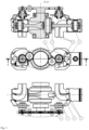
- FIG. 3 An embodiment of an engine with a rotary disk according to the invention is schematically shown in Fig. 3 .
- the shown design solution relates to a two-cylinder engine for driving an electric generator.
- Figure 3 shows the crankshaft mechanism of the engine.
- the exhaust port is designated by 2
- the intake port is designated by 3 .
- the engine has a cylinder bore of 70 mm and a stroke of 76 mm.
- the exhaust port height is 15 mm (wherein the lower edge is at the same height as the piston at the bottom dead center), and the piston is at the level of the upper edge of the exhaust port when the crankshaft is turned by 60° from the lower dead center. This means that during operation, the exhaust port starts to open 60° before the crankshaft bottom dead center and is completely closed 60° after the crankshaft bottom dead center. For example, for 10 mm high intake port, the same applies to a crankshaft rotation angle of 49°.
- the exhaust port at the location of the rotary disk has a square shape with a side length of 22 mm with rounded corners with a radius of 5 mm.
- the rotary disk of the type shown in Fig. 1a with a diameter of 108 mm needs an angular length of the protrusion of 42° to cover the exhaust port.
- the gear ratio may be varied over time to optimize timing, but the average gear ratio greater than one must always be an integer (1,2,3).
- the 3:1 gear ratio is the maximum option.
- a gear ratio less than 1 would have to be divisible by an integer (1:2, 1:3,...), the number of protrusions on the disk would correspond to the integer.
- the selected disk is unsuitable (small).
- the size of the rotary disk is important with respect to the moment of inertia and thus the power consumption of its drive.
- a larger disk means a greater moment of inertia, and therefore greater energy requirements when changing speed (dependent on acceleration).
- the size and position of the rotary disk is also affected by other engine components and installation dimensional requirements. If the axis of the disk is parallel to the axis of the crankshaft, the disk can be positioned very close to the cylinder, but the disk size is limited by the axial distances. If the disk is in another position, the distance of the disk affects the space of the crankcase, the cooling of the cylinder etc.
- the purpose of the rotary disk according to the invention is not to perfectly seal the exhaust port, but to create a significant pressure drop allowing to increase the charging pressure.
- the disk is mounted with clearance in its chamber, which extends into the exhaust port.
- the absence of friction of mechanical parts reduces mechanical losses and thus energy requirements for the disk drive.
Landscapes
- Engineering & Computer Science (AREA)
- Mechanical Engineering (AREA)
- General Engineering & Computer Science (AREA)
- Chemical & Material Sciences (AREA)
- Combustion & Propulsion (AREA)
- Output Control And Ontrol Of Special Type Engine (AREA)
- Cylinder Crankcases Of Internal Combustion Engines (AREA)
Applications Claiming Priority (2)
| Application Number | Priority Date | Filing Date | Title |
|---|---|---|---|
| CZ2020-184A CZ308792B6 (cs) | 2020-04-01 | 2020-04-01 | Dvoudobý spalovací motor |
| PCT/CZ2021/050035 WO2021197518A1 (en) | 2020-04-01 | 2021-03-23 | Two-stroke internal combustion engine |
Publications (3)
| Publication Number | Publication Date |
|---|---|
| EP4127421A1 EP4127421A1 (en) | 2023-02-08 |
| EP4127421C0 EP4127421C0 (en) | 2023-12-13 |
| EP4127421B1 true EP4127421B1 (en) | 2023-12-13 |
Family
ID=75438538
Family Applications (1)
| Application Number | Title | Priority Date | Filing Date |
|---|---|---|---|
| EP21717313.7A Active EP4127421B1 (en) | 2020-04-01 | 2021-03-23 | Two-stroke internal combustion engine |
Country Status (5)
| Country | Link |
|---|---|
| US (1) | US11828208B2 (cs) |
| EP (1) | EP4127421B1 (cs) |
| CZ (1) | CZ308792B6 (cs) |
| PL (1) | PL4127421T3 (cs) |
| WO (1) | WO2021197518A1 (cs) |
Family Cites Families (17)
| Publication number | Priority date | Publication date | Assignee | Title |
|---|---|---|---|---|
| US1535657A (en) * | 1917-05-08 | 1925-04-28 | Orville H Ensign | Method of and means for producing power from fuel |
| GB284649A (cs) * | 1927-02-02 | 1928-08-02 | Jean Roger Goiot | |
| US2082078A (en) * | 1933-07-15 | 1937-06-01 | Carl C Ottoson | Internal combustion engine |
| DE865237C (de) * | 1944-03-21 | 1953-02-12 | Otto Sierenberg | Steuerung fuer eine Zweitakt-Brennkraftmaschine mit Gleichstromspuelung |
| US2525271A (en) * | 1946-06-28 | 1950-10-10 | Quint George | Internal-combustion engine with complete expansion |
| US2720872A (en) * | 1953-01-30 | 1955-10-18 | Yokoi Motoaki | Two cycle internal combustion engines |
| IT1239937B (it) * | 1990-04-03 | 1993-11-23 | Gianfranco Bossu | Motore a combustione interna con luce di scarico sul cilindro |
| GB9217345D0 (en) * | 1992-08-14 | 1992-09-30 | Lotus Car | Four stroke internal combustion engine |
| US5257601A (en) * | 1993-02-01 | 1993-11-02 | Coffin David F | Adjustable rotary valve assembly for a combustion engine |
| US5331927A (en) * | 1993-10-07 | 1994-07-26 | General Motors Corporation | Exhaust port insert |
| JP3391413B2 (ja) * | 1993-11-27 | 2003-03-31 | 本田技研工業株式会社 | 2サイクルエンジンの排気制御弁 |
| US20030230258A1 (en) * | 2002-06-12 | 2003-12-18 | Niemiz Hector Alvaro Javier | Two-stroke engines exhaust and scavenge control |
| US7093570B2 (en) * | 2003-12-31 | 2006-08-22 | Nagesh S Mavinahally | Stratified scavenged two-stroke engine |
| US8578895B2 (en) * | 2010-02-17 | 2013-11-12 | Primavis S.R.L. | Two-stroke engine with low consumption and low emissions |
| US8997701B2 (en) * | 2011-02-24 | 2015-04-07 | University Of Idaho | Rotary synchronous charge trapping |
| DE102012020893B4 (de) * | 2012-10-24 | 2018-07-12 | Peter Kreuter | Verfahren zum Betreiben einer aufgeladenen, längsgespülten Zweitaktbrennkraftmaschine sowie aufgeladene, längsgespülte Zweitaktbrennkraftmaschine und Rekuperator |
| GB2557898B (en) * | 2016-10-17 | 2019-08-28 | Perkins Engines Co Ltd | Engine assembly for a combustion engine |
-
2020
- 2020-04-01 CZ CZ2020-184A patent/CZ308792B6/cs unknown
-
2021
- 2021-03-23 EP EP21717313.7A patent/EP4127421B1/en active Active
- 2021-03-23 PL PL21717313.7T patent/PL4127421T3/pl unknown
- 2021-03-23 US US17/915,072 patent/US11828208B2/en active Active
- 2021-03-23 WO PCT/CZ2021/050035 patent/WO2021197518A1/en not_active Ceased
Also Published As
| Publication number | Publication date |
|---|---|
| CZ2020184A3 (cs) | 2021-05-19 |
| EP4127421A1 (en) | 2023-02-08 |
| CZ308792B6 (cs) | 2021-05-19 |
| PL4127421T3 (pl) | 2024-05-20 |
| WO2021197518A1 (en) | 2021-10-07 |
| EP4127421C0 (en) | 2023-12-13 |
| US11828208B2 (en) | 2023-11-28 |
| US20230143774A1 (en) | 2023-05-11 |
Similar Documents
| Publication | Publication Date | Title |
|---|---|---|
| KR960007104B1 (ko) | 압축공기를 동력 매체로 하는 엔진 | |
| US3945359A (en) | Rotor engine | |
| US4011842A (en) | Piston machine | |
| JP2005503512A (ja) | 回転式シリンダを備えたピストン往復機関 | |
| US3927647A (en) | Rotary internal combustion engine | |
| JP5478741B2 (ja) | 低燃費低エミッション2ストロークエンジン | |
| JP4409772B2 (ja) | 弁なしエンジン | |
| KR20160089385A (ko) | 내연기관 | |
| US5197434A (en) | I.c. engines | |
| JP2000104556A (ja) | 回転式内燃機 | |
| CN109339940A (zh) | 一种转子与定子间导流式转子内燃机 | |
| EP4127421B1 (en) | Two-stroke internal combustion engine | |
| US6279518B1 (en) | Rotary engine having a conical rotor | |
| US4300487A (en) | Rotary engine | |
| US20140158080A1 (en) | Rotary Exhaust Valve | |
| RU2720879C1 (ru) | Роторно-поршневой двигатель внутреннего сгорания | |
| CN104641075B (zh) | 活塞装置以及内燃机 | |
| KR200226547Y1 (ko) | 로터리엔진 | |
| US10914205B2 (en) | Rotational valve for two stroke engine | |
| KR20090055707A (ko) | 세기 엔진 | |
| RU2300648C2 (ru) | Роторно-поршневой двухтактный двигатель внутреннего сгорания | |
| US10294792B2 (en) | Split-chamber rotary engine improvements | |
| GB1573552A (en) | Rotary internal combustion engine | |
| RU2313674C2 (ru) | Роторный двигатель внутреннего сгорания катасонова | |
| JPS644049B2 (cs) |
Legal Events
| Date | Code | Title | Description |
|---|---|---|---|
| STAA | Information on the status of an ep patent application or granted ep patent |
Free format text: STATUS: UNKNOWN |
|
| STAA | Information on the status of an ep patent application or granted ep patent |
Free format text: STATUS: THE INTERNATIONAL PUBLICATION HAS BEEN MADE |
|
| PUAI | Public reference made under article 153(3) epc to a published international application that has entered the european phase |
Free format text: ORIGINAL CODE: 0009012 |
|
| STAA | Information on the status of an ep patent application or granted ep patent |
Free format text: STATUS: REQUEST FOR EXAMINATION WAS MADE |
|
| 17P | Request for examination filed |
Effective date: 20221024 |
|
| AK | Designated contracting states |
Kind code of ref document: A1 Designated state(s): AL AT BE BG CH CY CZ DE DK EE ES FI FR GB GR HR HU IE IS IT LI LT LU LV MC MK MT NL NO PL PT RO RS SE SI SK SM TR |
|
| DAV | Request for validation of the european patent (deleted) | ||
| DAX | Request for extension of the european patent (deleted) | ||
| GRAP | Despatch of communication of intention to grant a patent |
Free format text: ORIGINAL CODE: EPIDOSNIGR1 |
|
| STAA | Information on the status of an ep patent application or granted ep patent |
Free format text: STATUS: GRANT OF PATENT IS INTENDED |
|
| INTG | Intention to grant announced |
Effective date: 20230712 |
|
| GRAS | Grant fee paid |
Free format text: ORIGINAL CODE: EPIDOSNIGR3 |
|
| GRAA | (expected) grant |
Free format text: ORIGINAL CODE: 0009210 |
|
| STAA | Information on the status of an ep patent application or granted ep patent |
Free format text: STATUS: THE PATENT HAS BEEN GRANTED |
|
| AK | Designated contracting states |
Kind code of ref document: B1 Designated state(s): AL AT BE BG CH CY CZ DE DK EE ES FI FR GB GR HR HU IE IS IT LI LT LU LV MC MK MT NL NO PL PT RO RS SE SI SK SM TR |
|
| REG | Reference to a national code |
Ref country code: GB Ref legal event code: FG4D |
|
| REG | Reference to a national code |
Ref country code: CH Ref legal event code: EP |
|
| REG | Reference to a national code |
Ref country code: DE Ref legal event code: R096 Ref document number: 602021007710 Country of ref document: DE |
|
| REG | Reference to a national code |
Ref country code: IE Ref legal event code: FG4D |
|
| U01 | Request for unitary effect filed |
Effective date: 20231217 |
|
| U07 | Unitary effect registered |
Designated state(s): AT BE BG DE DK EE FI FR IT LT LU LV MT NL PT SE SI Effective date: 20231221 |
|
| U20 | Renewal fee for the european patent with unitary effect paid |
Year of fee payment: 4 Effective date: 20240215 |
|
| REG | Reference to a national code |
Ref country code: SK Ref legal event code: T3 Ref document number: E 43374 Country of ref document: SK |
|
| PG25 | Lapsed in a contracting state [announced via postgrant information from national office to epo] |
Ref country code: GR Free format text: LAPSE BECAUSE OF FAILURE TO SUBMIT A TRANSLATION OF THE DESCRIPTION OR TO PAY THE FEE WITHIN THE PRESCRIBED TIME-LIMIT Effective date: 20240314 |
|
| PG25 | Lapsed in a contracting state [announced via postgrant information from national office to epo] |
Ref country code: ES Free format text: LAPSE BECAUSE OF FAILURE TO SUBMIT A TRANSLATION OF THE DESCRIPTION OR TO PAY THE FEE WITHIN THE PRESCRIBED TIME-LIMIT Effective date: 20231213 |
|
| PG25 | Lapsed in a contracting state [announced via postgrant information from national office to epo] |
Ref country code: GR Free format text: LAPSE BECAUSE OF FAILURE TO SUBMIT A TRANSLATION OF THE DESCRIPTION OR TO PAY THE FEE WITHIN THE PRESCRIBED TIME-LIMIT Effective date: 20240314 Ref country code: ES Free format text: LAPSE BECAUSE OF FAILURE TO SUBMIT A TRANSLATION OF THE DESCRIPTION OR TO PAY THE FEE WITHIN THE PRESCRIBED TIME-LIMIT Effective date: 20231213 |
|
| PG25 | Lapsed in a contracting state [announced via postgrant information from national office to epo] |
Ref country code: RS Free format text: LAPSE BECAUSE OF FAILURE TO SUBMIT A TRANSLATION OF THE DESCRIPTION OR TO PAY THE FEE WITHIN THE PRESCRIBED TIME-LIMIT Effective date: 20231213 Ref country code: NO Free format text: LAPSE BECAUSE OF FAILURE TO SUBMIT A TRANSLATION OF THE DESCRIPTION OR TO PAY THE FEE WITHIN THE PRESCRIBED TIME-LIMIT Effective date: 20240313 Ref country code: HR Free format text: LAPSE BECAUSE OF FAILURE TO SUBMIT A TRANSLATION OF THE DESCRIPTION OR TO PAY THE FEE WITHIN THE PRESCRIBED TIME-LIMIT Effective date: 20231213 |
|
| PG25 | Lapsed in a contracting state [announced via postgrant information from national office to epo] |
Ref country code: IS Free format text: LAPSE BECAUSE OF FAILURE TO SUBMIT A TRANSLATION OF THE DESCRIPTION OR TO PAY THE FEE WITHIN THE PRESCRIBED TIME-LIMIT Effective date: 20240413 |
|
| PG25 | Lapsed in a contracting state [announced via postgrant information from national office to epo] |
Ref country code: CZ Free format text: LAPSE BECAUSE OF FAILURE TO SUBMIT A TRANSLATION OF THE DESCRIPTION OR TO PAY THE FEE WITHIN THE PRESCRIBED TIME-LIMIT Effective date: 20231213 |
|
| PG25 | Lapsed in a contracting state [announced via postgrant information from national office to epo] |
Ref country code: SM Free format text: LAPSE BECAUSE OF FAILURE TO SUBMIT A TRANSLATION OF THE DESCRIPTION OR TO PAY THE FEE WITHIN THE PRESCRIBED TIME-LIMIT Effective date: 20231213 Ref country code: RO Free format text: LAPSE BECAUSE OF FAILURE TO SUBMIT A TRANSLATION OF THE DESCRIPTION OR TO PAY THE FEE WITHIN THE PRESCRIBED TIME-LIMIT Effective date: 20231213 Ref country code: IS Free format text: LAPSE BECAUSE OF FAILURE TO SUBMIT A TRANSLATION OF THE DESCRIPTION OR TO PAY THE FEE WITHIN THE PRESCRIBED TIME-LIMIT Effective date: 20240413 Ref country code: CZ Free format text: LAPSE BECAUSE OF FAILURE TO SUBMIT A TRANSLATION OF THE DESCRIPTION OR TO PAY THE FEE WITHIN THE PRESCRIBED TIME-LIMIT Effective date: 20231213 |
|
| REG | Reference to a national code |
Ref country code: DE Ref legal event code: R097 Ref document number: 602021007710 Country of ref document: DE |
|
| PLBE | No opposition filed within time limit |
Free format text: ORIGINAL CODE: 0009261 |
|
| STAA | Information on the status of an ep patent application or granted ep patent |
Free format text: STATUS: NO OPPOSITION FILED WITHIN TIME LIMIT |
|
| REG | Reference to a national code |
Ref country code: CH Ref legal event code: PL |
|
| 26N | No opposition filed |
Effective date: 20240916 |
|
| PG25 | Lapsed in a contracting state [announced via postgrant information from national office to epo] |
Ref country code: MC Free format text: LAPSE BECAUSE OF FAILURE TO SUBMIT A TRANSLATION OF THE DESCRIPTION OR TO PAY THE FEE WITHIN THE PRESCRIBED TIME-LIMIT Effective date: 20231213 |
|
| PG25 | Lapsed in a contracting state [announced via postgrant information from national office to epo] |
Ref country code: MC Free format text: LAPSE BECAUSE OF FAILURE TO SUBMIT A TRANSLATION OF THE DESCRIPTION OR TO PAY THE FEE WITHIN THE PRESCRIBED TIME-LIMIT Effective date: 20231213 |
|
| PG25 | Lapsed in a contracting state [announced via postgrant information from national office to epo] |
Ref country code: IE Free format text: LAPSE BECAUSE OF NON-PAYMENT OF DUE FEES Effective date: 20240323 |
|
| PG25 | Lapsed in a contracting state [announced via postgrant information from national office to epo] |
Ref country code: IE Free format text: LAPSE BECAUSE OF NON-PAYMENT OF DUE FEES Effective date: 20240323 Ref country code: CH Free format text: LAPSE BECAUSE OF NON-PAYMENT OF DUE FEES Effective date: 20240331 |
|
| U20 | Renewal fee for the european patent with unitary effect paid |
Year of fee payment: 5 Effective date: 20250319 |
|
| PGFP | Annual fee paid to national office [announced via postgrant information from national office to epo] |
Ref country code: PL Payment date: 20250224 Year of fee payment: 5 |
|
| PGFP | Annual fee paid to national office [announced via postgrant information from national office to epo] |
Ref country code: SK Payment date: 20250127 Year of fee payment: 5 Ref country code: GB Payment date: 20250318 Year of fee payment: 5 |
|
| PGFP | Annual fee paid to national office [announced via postgrant information from national office to epo] |
Ref country code: TR Payment date: 20250227 Year of fee payment: 5 |
|
| PG25 | Lapsed in a contracting state [announced via postgrant information from national office to epo] |
Ref country code: CY Free format text: LAPSE BECAUSE OF FAILURE TO SUBMIT A TRANSLATION OF THE DESCRIPTION OR TO PAY THE FEE WITHIN THE PRESCRIBED TIME-LIMIT; INVALID AB INITIO Effective date: 20210323 |
|
| PG25 | Lapsed in a contracting state [announced via postgrant information from national office to epo] |
Ref country code: HU Free format text: LAPSE BECAUSE OF FAILURE TO SUBMIT A TRANSLATION OF THE DESCRIPTION OR TO PAY THE FEE WITHIN THE PRESCRIBED TIME-LIMIT; INVALID AB INITIO Effective date: 20210323 |
|
| U20 | Renewal fee for the european patent with unitary effect paid |
Year of fee payment: 6 Effective date: 20260129 |