EP4126687B1 - Behälter mit wiederverwendbarer kappe - Google Patents
Behälter mit wiederverwendbarer kappe Download PDFInfo
- Publication number
- EP4126687B1 EP4126687B1 EP21715597.7A EP21715597A EP4126687B1 EP 4126687 B1 EP4126687 B1 EP 4126687B1 EP 21715597 A EP21715597 A EP 21715597A EP 4126687 B1 EP4126687 B1 EP 4126687B1
- Authority
- EP
- European Patent Office
- Prior art keywords
- annular
- region
- cap
- sealing ring
- closing portion
- Prior art date
- Legal status (The legal status is an assumption and is not a legal conclusion. Google has not performed a legal analysis and makes no representation as to the accuracy of the status listed.)
- Active
Links
Images


Classifications
-
- B—PERFORMING OPERATIONS; TRANSPORTING
- B65—CONVEYING; PACKING; STORING; HANDLING THIN OR FILAMENTARY MATERIAL
- B65D—CONTAINERS FOR STORAGE OR TRANSPORT OF ARTICLES OR MATERIALS, e.g. BAGS, BARRELS, BOTTLES, BOXES, CANS, CARTONS, CRATES, DRUMS, JARS, TANKS, HOPPERS, FORWARDING CONTAINERS; ACCESSORIES, CLOSURES, OR FITTINGS THEREFOR; PACKAGING ELEMENTS; PACKAGES
- B65D41/00—Caps, e.g. crown caps or crown seals, i.e. members having parts arranged for engagement with the external periphery of a neck or wall defining a pouring opening or discharge aperture; Protective cap-like covers for closure members, e.g. decorative covers of metal foil or paper
- B65D41/02—Caps or cap-like covers without lines of weakness, tearing strips, tags, or like opening or removal devices
- B65D41/04—Threaded or like caps or cap-like covers secured by rotation
- B65D41/0435—Threaded or like caps or cap-like covers secured by rotation with separate sealing elements
- B65D41/0442—Collars or rings
-
- B—PERFORMING OPERATIONS; TRANSPORTING
- B65—CONVEYING; PACKING; STORING; HANDLING THIN OR FILAMENTARY MATERIAL
- B65D—CONTAINERS FOR STORAGE OR TRANSPORT OF ARTICLES OR MATERIALS, e.g. BAGS, BARRELS, BOTTLES, BOXES, CANS, CARTONS, CRATES, DRUMS, JARS, TANKS, HOPPERS, FORWARDING CONTAINERS; ACCESSORIES, CLOSURES, OR FITTINGS THEREFOR; PACKAGING ELEMENTS; PACKAGES
- B65D41/00—Caps, e.g. crown caps or crown seals, i.e. members having parts arranged for engagement with the external periphery of a neck or wall defining a pouring opening or discharge aperture; Protective cap-like covers for closure members, e.g. decorative covers of metal foil or paper
- B65D41/02—Caps or cap-like covers without lines of weakness, tearing strips, tags, or like opening or removal devices
- B65D41/04—Threaded or like caps or cap-like covers secured by rotation
- B65D41/0492—Threaded or like caps or cap-like covers secured by rotation formed by several elements connected together
-
- B—PERFORMING OPERATIONS; TRANSPORTING
- B65—CONVEYING; PACKING; STORING; HANDLING THIN OR FILAMENTARY MATERIAL
- B65D—CONTAINERS FOR STORAGE OR TRANSPORT OF ARTICLES OR MATERIALS, e.g. BAGS, BARRELS, BOTTLES, BOXES, CANS, CARTONS, CRATES, DRUMS, JARS, TANKS, HOPPERS, FORWARDING CONTAINERS; ACCESSORIES, CLOSURES, OR FITTINGS THEREFOR; PACKAGING ELEMENTS; PACKAGES
- B65D51/00—Closures not otherwise provided for
- B65D51/14—Rigid discs or spherical members adapted to be held in sealing engagement with mouth of container, e.g. closure plates for preserving jars
- B65D51/145—Rigid discs or spherical members adapted to be held in sealing engagement with mouth of container, e.g. closure plates for preserving jars by means of an additional element connected directly to the container
-
- B—PERFORMING OPERATIONS; TRANSPORTING
- B65—CONVEYING; PACKING; STORING; HANDLING THIN OR FILAMENTARY MATERIAL
- B65D—CONTAINERS FOR STORAGE OR TRANSPORT OF ARTICLES OR MATERIALS, e.g. BAGS, BARRELS, BOTTLES, BOXES, CANS, CARTONS, CRATES, DRUMS, JARS, TANKS, HOPPERS, FORWARDING CONTAINERS; ACCESSORIES, CLOSURES, OR FITTINGS THEREFOR; PACKAGING ELEMENTS; PACKAGES
- B65D53/00—Sealing or packing elements; Sealings formed by liquid or plastics material
- B65D53/02—Collars or rings
-
- B—PERFORMING OPERATIONS; TRANSPORTING
- B65—CONVEYING; PACKING; STORING; HANDLING THIN OR FILAMENTARY MATERIAL
- B65D—CONTAINERS FOR STORAGE OR TRANSPORT OF ARTICLES OR MATERIALS, e.g. BAGS, BARRELS, BOTTLES, BOXES, CANS, CARTONS, CRATES, DRUMS, JARS, TANKS, HOPPERS, FORWARDING CONTAINERS; ACCESSORIES, CLOSURES, OR FITTINGS THEREFOR; PACKAGING ELEMENTS; PACKAGES
- B65D79/00—Kinds or details of packages, not otherwise provided for
- B65D79/005—Packages having deformable parts for indicating or neutralizing internal pressure-variations by other means than venting
- B65D79/0087—Packages having deformable parts for indicating or neutralizing internal pressure-variations by other means than venting the deformable part being located in a closure, e.g. in caps or lids
-
- Y—GENERAL TAGGING OF NEW TECHNOLOGICAL DEVELOPMENTS; GENERAL TAGGING OF CROSS-SECTIONAL TECHNOLOGIES SPANNING OVER SEVERAL SECTIONS OF THE IPC; TECHNICAL SUBJECTS COVERED BY FORMER USPC CROSS-REFERENCE ART COLLECTIONS [XRACs] AND DIGESTS
- Y02—TECHNOLOGIES OR APPLICATIONS FOR MITIGATION OR ADAPTATION AGAINST CLIMATE CHANGE
- Y02W—CLIMATE CHANGE MITIGATION TECHNOLOGIES RELATED TO WASTEWATER TREATMENT OR WASTE MANAGEMENT
- Y02W30/00—Technologies for solid waste management
- Y02W30/50—Reuse, recycling or recovery technologies
- Y02W30/80—Packaging reuse or recycling, e.g. of multilayer packaging
Definitions
- the present invention is directed to a container, for example a vacuum, gas and liquid tight container, with a reusable cap.
- the container can be used for storage and, when it is a vacuum tight container, it can maintain an inner gas pressure lower than the ambient air without collapsing, which is appropriate mainly for food conservation and storage.
- the cap in order to be reusable, is made of a durable and oxide-resistant material and include a releasable sealing ring allowing for cleaning operations.
- Document US3307728 describes a container with a cap made of a folded metal sheet, said cap comprising a closing portion for completely covering the receptacle opening, and an independent engagement portion to provide engagement between the cap and the receptacle producing a compression force on the closing portion towards the annular mouth.
- Document US3219223 describes a container similar to the previously described solution in which the closing portion includes a sealing ring molded in, and therefore adhered to, the closing portion.
- the adherence of the sealing ring to the closing portion is further increased by the periphery of the sealing ring being inserted in an annular groove defined in the periphery of the closing portion.
- the cap is made of a weak material, such aluminum, selected to be deformed by pressing the engagement portion thereof against the thread of the receptacle, causing the deformation of the cap which adopts the shape of the thread of the receptacle against which it is pressed. Therefore, because it is made of a deformable material, said engagement portion could be easily deformed or bended accidentally during manipulation operations, reducing the reusability of the cap.
- US2092192A describes a container with a reusable cap according to the preamble of independent claim 1.
- the tinplate and other metals shall be varnished or painted to prevent oxidation and to permit the adhesion of the sealing ring thereon, and this varnish or paint enters in contact with the food or beverage stored in the container.
- these materials and their applications makes it unlikely to be reused due to potential interferences of the varnish in utilization.
- the present invention proposes, in a manner already known in the state of the art, a vacuum, gas and liquid tight container with a reusable cap including:
- Said retention configuration can be, for example, a thread, housings on opposed sides of the cylindrical neck, an annular recess or an annular collar.
- the cap can be attached or released from the glass receptacle by a releasable closure mechanism configured engaging the cap with the retention configurations of the glass receptacle in a releasable manner.
- the releasable closure mechanism comprises engagement configurations, included in an engagement portion of the cap, which are complementary to a thread of the cylindrical neck, constitutive of the retention configurations.
- Said engagement configurations are defined by local deformations or folds of the metal sheet constitutive of the engagement portion of the cap.
- the retention configurations of the cylindrical neck can be defined by a thread surrounding said cylindrical neck and the releasable closure mechanism can be a threaded ring, independent from the cap, surrounding the cylindrical segment and including engagement configurations complementary to the thread, said threaded ring further including a ring mouth segment overlapped to a perimeter area of the closing portion, retaining said closing portion against the annular mouth of the glass receptacle.
- the releasable closure mechanism can also be defined by several clip members each connecting, under elastic stress, the retention configurations of the cylindrical neck with the cap when the cap is in closed position.
- the releasable closure mechanism comprises a shaped metal wire defining a first region configured for being connected to the cap, at least when in the closed position; a second region configured for being attached to the glass receptacle; and a third region connected to the second region and configured for being movable between a first position, in which the third region is connected to the first region under elastic stress, attracting the first region to the annular mouth of the glass receptacle, and a second position in which the third region is free of elastic stress and the first region is spaced apart from the annular mouth of the glass receptacle or is released from the third region.
- the first region can be connected to the cap by its insertion in one or multiple depressions of the cylindrical segment defined in an outer back side of the one or multiple radial protrusions of the cylindrical segment.
- the radial protrusions are defined by a local bending of the metal sheet constitutive of the engagement portion of the cap, said local bending defining simultaneously the radial protrusions and depressions in the outer side of the engagement portion, where the first region can be housed.
- the second region can be connected to the retention configurations of the glass receptacle by surrounding the cylindrical neck, preferably being inserted in a groove of said cylindrical neck or retained by an annular protrusion surrounding said cylindrical neck.
- the first region and the second region are connected to each other in an articulated manner in a first side of the cylindrical neck of the glass receptacle, and the third region is connected in an articulated manner to the second region in a second side of the cylindrical neck opposed to the first side, the connection between the first and third regions being configured to be releasable when in the open position.
- the second region and the third region are connected to each other, and the first region is connected to the third region in an articulated manner, being configured to remain connected to the third region in both the closed and the open positions.
- the sealing ring can be made of a suitable air-tight elastic or deformable material, such thermoplastic, plastic, rubber, silicone, cork or others.
- the one or multiple radial protrusions of the cylindrical segment can be one or multiple tapered surfaces determining an inner diameter of the cylindrical segment that increases as the distance from the closing portion decreases, retaining the sealing ring.
- the closing portion includes an inner annular protrusion, which is concentric with the cylindrical segment and protrudes towards the receptacle opening, the sealing ring being compressed between the annular mouth and the inner annular protrusion and being retained in a centered position between said inner annular protrusion and the inner diameter of the cylindrical segment.
- the closing portion includes an inner annular protrusion.
- said inner annular protrusion is a continuous protrusion with a circular shape and concentric with the cylindrical segment and therefore also concentric with the annular mouth of the glass receptacle when the cap is attached thereto.
- Said inner annular protrusion protrudes from the closing portion towards the receptacle opening when the cap is attached to the glass receptacle, it is to say towards the interior of the cap.
- the sealing ring When the cap is attached to the glass cap the sealing ring is compressed between the annular mouth of the glass receptacle and said inner annular protrusion, concentrating most or all the compression force applied to the sealing ring by the cap on said inner annular protrusion, increasing the obtained sealing without increasing the closing and opening force required to open and close the cap, preventing the entrance of food or beverage between the sealing ring and the annular mouth and/or the closing portion of the cap.
- the sealing ring is retained between said inner annular protrusion and the inner diameter of the cylindrical segment when the cap is attached to the glass receptacle, preventing an undesired radial movement of the sealing ring, for example due to the suction produced by a vacuum existent within the glass receptacle, or due to an overpressure existent within the glass receptacle during its heating for example for an sterilization process.
- the inner annular protrusion has a height equal to or greater than 60% or preferably 70%, of the thickness of the sealing ring to ensure a proper retention of the sealing ring, specially when the sealing ring is made of a material which softens when heated, such a thermoplastic.
- the cylindrical segment of the engagement portion further comprises radial protrusions directed inwards, said radial protrusions being formed by local deformations of the metal sheet. It will be understood that the radial direction and the inward direction are defined in regard to the center of the engagement portion which has a general cylindrical shape which is concentric and surrounds the cylindrical neck of the glass receptacle when the cap is attached to the glass receptacle.
- Said radial protrusions can be placed between the closing portion and the engagement configurations of the cap determining a local narrowing of the inner diameter of the cylindrical segment, it is to say a reduction in its inner diameter.
- the sealing ring is not adhered to the cap, so it is loose in regard to the cap.
- Said sealing ring is bigger than the local narrowing of the inner diameter of the cylindrical segment produced by the radial protrusions, so that its outer region interferes with the radial protrusions retaining the sealing ring within the cap between the closing portion and the radial protrusions preventing its fall from the cap when the cap is unscrewed from the glass receptacle.
- This feature allows the sealing ring to be retained within the cap even when the cap is separated from the glass receptacle, but allowing the release of the sealing ring from the cap by elastic deformation of the sealing ring for cleaning or substitution, increasing the reusability of the cap.
- the local narrowing has a diameter bigger than the cylindrical outer surface of the cylindrical neck. Because the sealing ring has an outer diameter bigger than the local narrowing, and preferably equal to the inner diameter of the cylindrical segment of the engagement portion, the sealing ring extends far beyond the outer edge of the annular mouth.
- the proposed configuration makes easier to break the hermetic seal.
- the cap is unscrewed from the thread of the glass receptacle the radial protrusions moves upwards pulling up the outer region of the sealing ring, producing the deformation of the sealing ring and facilitating its separation from the annular mouth and the breakage of the hermetic sealing.
- the sealing ring includes an annular portion and a tab portion connected to a connection region of the annular portion, said tab portion projecting in an outwardly radial direction through a passage defined in the cylindrical segment between the closing portion and the radial protrusions.
- the flat sealing ring includes a deformation enhancer configuration comprising:
- the tab portion which extends radially from the annular portion, produces a local decrease in the deformability of the connection region in comparison with the rest of the annular portion because said tab portion determines a local increase of the flat sealing ring width in the radial direction. This reduced deformability jeopardizes and makes it difficult the airtight sealing breakage when the user pulls the tab portion.
- any of the proposed configurations produces an increase in the deformability of the annular portion in the connection region and in surrounding areas when the tab portion is pulled by the user, because the proposed deformation enhancer configuration reduces the cross section area of the flat sealing ring without endangering the airtight sealing, allowing for an easier release of the vacuum by pulling the tab portion.
- the deformation enhancer configuration is a through hole placed on the tab portion adjacent to the connection region, and preferably in contact or tangent with said connection region, said through hole interrupts the continuity of the material constitutive of the flat sealing ring, therefore increasing its deformability.
- the deformation enhancer configuration is a thickness reduction placed on the tab portion adjacent to the connection region, and preferably in contact or tangent with said connection region, said thickness reduction reduces the mass of material constitutive of the flat sealing ring, therefore increasing its deformability.
- said at least one through hole is one through hole placed between two lateral edges of the tab portion, dividing the tab portion in two branches, and preferably it is placed on a half of the tab portion closer to the connection region of the sealing annular portion.
- the tab portion has two halves, one adjacent to the connection region containing the through hole, and one half away from the connection region.
- the through hole is centered, said two branches being symmetric over a radial axis which extends outwards in a radial direction coplanar with the flat sealing ring and perpendicular to the connection region of the annular portion, to ensure a symmetric deformation of the flat sealing ring and preventing undesired stress concentrations.
- each branch is at most one and half times the maximal width of the through hole measured in a direction parallel to the junction between the tab portion and the connection region. This relationship ensures a sufficient deformability enhance without producing a breakage risk.
- the through hole is perpendicular to a main surface of the tab portion and is circular to prevent stress concentrations.
- the deformation enhancer configuration includes a notch
- said notch will preferably reduce equal or less than one fifth of the width of the connection region, i.e. that the width of the annular portion, where includes said notch, is at least four fifths of the width on the rest of the annular portion.
- said notch does not affect the area of the annular portion of the flat sealing ring compressed between the annular mouth and the perimetral region of the rigid lid.
- the flat sealing ring can be made of rubber or silicone.
- the thickness reduction of the deformation enhancer configuration can be an elongated groove parallel to the junction between the tab portion and the connection portion.
- Said thickness reduction of the deformation enhancer configuration can be also defined on both sides of the tab portion, for example as two symmetric grooves defined on opposed sides of the tab portion.
- Said gripping enhancer configurations include holes, grooves, and/or protrusions on one or both main surfaces of the tab portion. Said gripping enhancer configurations provide an enhanced gripping of the tab portion for pulling.
- the gripping enhancer configurations can be included at least on a half of the tab portion away from the connection portion, which is the most accessible part of the tab portion for a user.
- the gripping enhancer configurations are, for example, lineal grooves and/or protrusions oriented in a non-radial direction.
- the gripping and the deformation enhancer configurations consistent in a local variation in the thickness of the flat sealing ring will be preferably obtained by thermo-forming said flat sealing ring.
- radial direction is a direction contained in a plane coplanar with the flat sealing ring when compressed between the rigid receptacle and the rigid lid which extends outwardly from a center of the annular mouth.
- the cap is made of stainless steel, which is a durable material because it does not rust and because it is a hard and resistant which cannot be easily deformed accidentally. Furthermore, the stiffness of the stainless steel reduces the deformations produces on the cap when is attached to the glass receptacle, assuring a better transmission of the compression force from cap to the sealing ring, permitting the application of a greater compression force on said sealing ring achieving an improved sealing.
- Said stainless steel cap is preferably unpainted and unvarnished, preventing the contact of the food or beverage contained in the receptacle with potentially hazardous substances presents on varnishes and paints.
- the unpainted and unvarnished stainless steel is not compatible with adhesives, preventing the adhesion of a sealing ring on it.
- said one or more radial protrusions is one continuous protrusion surrounding the cylindrical segment, producing a better retention of the sealing ring and a uniform deformation of all the outer region thereof.
- the radial protrusions are multiple discrete protrusions, making easier the insertion and extraction of the sealing ring.
- the inner annular protrusion of the closing portion can be:
- the inner edge of the annular mouth is the circular edge of the annular mouth having the smallest diameter, and the outer edge of the annular mouth is the circular edge of the annular mouth having the biggest diameter.
- said inner edge can be flattened producing a frustoconical surface parallel to the frustoconical surface of the inner annular protrusion.
- the inner region of the sealing ring is the region thereof closest to the center of the sealing ring, and the outer region is the region thereof farthest from the center of the sealing ring.
- Said frustoconical surface is preferably defined as a circular step between two non-coplanar regions of the closure portion.
- Preferably said frustoconical surface is vertically aligned with or vertically adjacent to the inner edge of the annular mouth when the cap is attached to the glass receptacle. Said inner edge of the annular mouth can be flattened.
- Said protrusion having a V-shaped section is defined by an annular deformation of the metal sheet constitutive of the closing portion of the cap, producing an annular groove and one complementary annular protrusion on opposed sides of the closing portion of the cap.
- the closing portion further comprises an outer annular protrusion which is concentric with the cylindrical segment, surrounding the inner annular protrusion, and which protrudes towards the receptacle opening, the sealing ring being compressed between the annular mouth and the outer annular protrusion, preventing the entrance of air between the sealing ring and the annular mouth and/or the closing portion of the cap.
- said outer annular protrusion is vertically aligned with or vertically adjacent to the outer edge of the annular mouth.
- Said outer annular protrusion can be, for example:
- said outer edge can be flattened and can produce a frustoconical surface parallel to the frustoconical surface of the outer annular protrusion.
- the closing portion is in contact with the sealing ring only through the inner annular protrusion or only through the inner and the outer annular protrusions, so that all the compression force applied by the cap to the sealing ring is concentrate on that areas, improving the sealing.
- the closing portion and the engagement portion of the cap are independent to each other, two separated elements.
- the engagement portion will further comprise a ring mouth segment overlapped to a perimeter area of the closing portion, retaining said closing portion between the ring mouth segment and the sealing ring.
- the sealing ring is retained within the cap by said radial protrusions directed inwards, and the closing portion is retained within the cap between the sealing ring and the ring mouth segment of the engagement portion.
- the closing portion has an outer diameter equal or smaller than the narrowing of the inner diameter of the cylindrical segment and equal or smaller than the engagement configurations of the cylindrical segment so that, once the sealing ring is removed, the closing portion can be also removed from the cap for cleaning or renovation operations.
- the sizes are equal a little pressure can be required to extract said closing portion from the cap.
- the closing portion can also include a bumped central area collapsible under a vacuum existent in the interior of the container as a tamper evidence.
- the metal sheet of the engagement portion has a first thickness
- the closing portion is made of a metal sheet with a second thickness smaller than the first thickness, obtaining a stiffer and more durable engagement portion and a closing portion with sufficient flexibility to permit the collapse of the bumped central area under certain predefined vacuum level.
- the first thickness is comprised between 0,3mm and 0,2mm and the second thickness is comprised between 0,15mm and 0,1mm, and preferably the sealing ring has a thickness comprised between 1,5mm and 2,5mm.
- the closing portion can be made of a different material than the engagement portion.
- the closing portion can be made of glass, ceramic, plastic, or can be an open mesh.
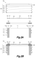
- the present invention is directed to a vacuum, gas and liquid tight container with a reusable cap 20.
- Said container is made of three principal parts: a glass receptacle 10 with a receptacle opening 11, a cap 20 with a closing portion 30 completely covering said receptacle opening 11 and a sealing ring 50 compressed therebetween providing a tight seal.
- the glass receptacle 10 further comprises a cylindrical neck 13 including an annular mouth 12 on one end, said cylindrical neck 13 and annular mouth 12 surrounding the receptacle opening 11.
- the cylindrical neck 13 further comprises a thread 14 on its outer surface.
- the cap 20 is made of metal sheet and includes said closing portion 30 and an engagement portion 40 which includes a cylindrical segment 43 with an inner diameter surrounding the cylindrical neck 13. Said cylindrical segment 43 includes engagement configurations 44 defined by local deformations of the metal sheet which are complementary to the thread 14 of the glass receptacle.
- Said engagement configurations 44 are protrusions of the cylindrical segment 43 projecting inwards the cap 20 in positions adapted to engage with the thread when the cap 20 is coupled to the glass receptacle 10.
- Said engagement configurations 44 provide an attachment of the cap 20 to the glass receptacle 10 and generates a compression force which pushes the closing portion 30 towards the annular mouth 12 of the glass receptacle 10, generating a compression force on the sealing ring 50 placed there between.
- the sealing ring 50 has an outer diameter equal to or smaller than the inner diameter of the cylindrical segment 43 and is compressed between the annular mouth 12 and the closure portion 30 providing said tight seal.
- the cylindrical segment 43 further includes, between the closing portion 30 and the engagement configurations 44, one continuous radial protrusion 41 surrounding all the cylindrical segment 43 and defining a local narrowing on the inner diameter of the cylindrical segment 43.
- the sealing ring 50 which is not adhered to the cap 20, has an outer diameter bigger than the local narrowing and equal or smaller than the inner diameter of the cylindrical segment 43, so that said sealing ring 50 can be introduced by elastic deformation into the cap 20, surrounded by the cylindrical segment 43, and retained between the radial protrusion 41 and the coupling portion 30.
- the sealing ring 50 is retained in the cap 20 by said radial protrusions 41 even when the cap 20 is separated from the glass receptacle 10, but it can be removed by elastic deformation for cleaning operations.
- An additional function of said radial protrusion 41 is to rise the periphery of the sealing ring 50 during the opening of the container, producing the deformation of the sealing ring 50 facilitating the entrance of gases and the breakage of a vacuum existing in the glass receptacle.
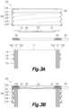
- the closing portion includes two regions non-coplanar two each other connected through the inner annular protrusion 31 which has a frustoconical shape, the region facing the receptacle opening 11 being at a lower level than the region facing the annular mouth 12.
- the inner annular protrusion 31 with frustoconical shape faces the inner edge 12a of the annular mouth 12, compressing the sealing ring 50 against said inner edge 12a.
- the closing portion includes two circular concentric grooves defined by two annular deformations of the metal sheet, each of said grooves having an V-shaped cross section and defining an inner annular protrusion 31 and an outer annular protrusion 32 on the side of the closing portion 30 facing the annular mouth 12.
- the inner annular protrusion 31 compresses the sealing ring 50 against the inner edge 12a of the annular mouth 12, and the outer annular protrusion 32 compresses the sealing ring 50 against the outer edge 12b of the annular mouth 12. It will be evident that the outer annular protrusion 32 is optional.
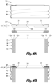
- the cap 20 is made of a single metal sheet defining therein the engagement portion 40 and the closing portion 30.
- the retention configurations of the cylindrical neck 13 can be defined by a thread 14 surrounding said cylindrical neck 13 and wherein the releasable closure mechanism is a threaded ring 70, independent from the cap 20, surrounding the cylindrical segment 43 and including engagement configurations 44 complementary to the thread 14, said threaded ring further including a ring mouth segment 45 overlapped to a perimeter area of the closing portion, retaining said closing portion against the annular mouth of the glass receptacle.
- the releasable closure mechanism is a threaded ring 70, independent from the cap 20, surrounding the cylindrical segment 43 and including engagement configurations 44 complementary to the thread 14, said threaded ring further including a ring mouth segment 45 overlapped to a perimeter area of the closing portion, retaining said closing portion against the annular mouth of the glass receptacle.
- the cap 20 is made of two separated and independent parts, one corresponding to the closing portion 30 and one corresponding to the engagement portion 40, which in this case further comprises a ring mouth segment 45 connected to the cylindrical segment 43 and covering a perimetral region of the closing portion 30 placed above the sealing ring 50. Said ring mouth segment 45 transfers the compression force from the cylindrical segment 43 to the closing portion 30.
- the closing portion 30 preferably has an outer diameter equal or smaller than the engagement configurations 44, and equal or smaller than the radial protrusion 41, permitting the extraction of said closing portion 30 from the cap 20 for cleaning operations.
- the sealing ring 50 retained within the cap 20 by the radial protrusions 41 will also retain said closing portion 30 while in place.
- bumped central area 33 collapsible under a vacuum existent in the interior of the container as a tamper evidence.
- said bumped central area 33 projects outwards from the cap 20, as shown on Fig. 3a , but when the cap 20 is closed and certain amount of vacuum is created within the glass receptacle 20, then the bumped central area 33 collapses and inverts it position to project inwards, as shown on Fig. 3b .
- the closing portion 30 can be made of a thinner metal sheet than the engagement portion 40 so that the bumped central area 33 can collapse under a small level of vacuum existent in the interior of the container and at the same time the engagement portion is stiff and does not bend or deform easily.
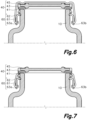
- the closure mechanism consists of a first wire, corresponding to the first region 61, having an inverted U shape with a flat region overlapped to the cap and a second wire, corresponding to the second and third regions 62, 63, having a U shape with a rounded bottom including symmetrical portions 63a and 63b in the form of loops in areas close to their ends.
- the ends of the second wire constitute the second region 62 and are inserted into respective housings arranged on opposite sides of the glass receptacle 10, adjacent to the mouth 11 providing an articulated attachment between the second wire and the receptacle 10.
- the ends of the first wire are inserted into respective opposite portions 63a and 63b in the form of loops of the second wire, on opposite sides of the outside of the receptacle 10, providing an articulated attachment between the first wire and the second wire.
- the first wire is superimposed on the ring mouth segment 45 of the cap 20 in the closed position, and the second wire allows, according to its position, moving the symmetrical portions 63a and 63b in the form of loops to which the first wire is articulated in a vertical direction, with the vertical stress of the first wire on the ring mouth segment 45 of the cap 20 being exerted against the mouth 11 of the receptacle 10, assuring hermetic closure thereof.
- the first wire is inserted in a groove corresponding to the back side of the radial protrusions.
- the first wire constitutes a first region 61 intended for pressing the lid 20 against the receptacle 10
- the portions 63a and 63b of the second wire constitute a third region 63 of the closure mechanism intended for connecting the closure mechanism to the receptacle 10 producing an elastic stress, attracting the first region 61 downwards, and serving as a supporting point for subjecting the second region to elastic stress.
- the third region is connected to the glass receptacle 10 in an articulated manner through the second region 62.
- the portion of the second wire comprised between the symmetrical portions 63a and 63b in the form of loops is a lever arm which allows a simultaneous and symmetrical actuation of the two symmetrical portions 63a and 63b, locating the closure mechanism in the closed or open position in which the lid 20 is released, allowing it to be removed from the mouth 11 of the receptacle 10.
- the closure mechanism consists of a single shaped wire having an inverted U shape and a flat bottom.
- Said metal wire will have a first region 61 in its central area, intended for being attached to the cap 20 as in the examples described before, a third region 63 defined in two portions 63a and 63b located in areas close to the ends of the wire, intended for being subjected to certain elastic stress when the closure mechanism is in the closed position, and a second region 62 corresponding to the two ends of the wire, said second region being complementary to an annular groove arranged around the mouth 11 of the receptacle 10, provided for fitting said second region 62 therein, and therefore serving as a supporting point so that the third region 63 can provide elastic stress to the first region 61 which transmits it to the lid 20 through two opposite points of the annular closure rib 22.
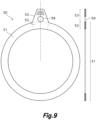
- the cylindrical segment (43) can include a slit passage 49 between the closing portion 30 and the radial protrusions 41, facing a side edge of the sealing ring 50, or at least partially included in said radial protrusion 41.
- a flat tool such as a round knife, can be inserted for pushing the sealing ring 50 inwards, breaking the vacuum.
- the flat sealing ring 50 further comprises a tab portion 53 extending outwards from the annular portion 51, away from said central opening, through the slit passage 49. Said tab portion 53 is accessible from the exterior of the container by a user for pulling the flat sealing ring 50 outwards in a radial direction coplanar with said flat sealing ring 50 for breaking the vacuum defined within the container.
- connection region 52 The region of the annular portion 51 wherein the tab portion 53 is attached is named connection region 52.
- the proposed deformation enhancer configuration 59 comprises a circular through hole adjacent to the connection region 52.
- said through hole is fully comprised in the half of the tab portion 53 closer to the connection region 52.
- each branch divides the tab portion 53 in two symmetric branches.
- the minimal width of each branch is equal to or smaller than the maximal width of the through hole. It is also preferred that each branch has a minimal width equal to or bigger than two times its thickness.
- the deformation enhancer configuration 59 is a linear groove contained in the tab portion 53 and adjacent to the connection region 52, producing a thickness reduction of the tab portion 53 in comparison with the thickness of the annular portion 51.
- the deformation enhancer configuration 59 is a notch of the inner edge of the annular portion 51 which surrounds the central opening. Said notch produces a width reduction of the annular portion 51 coincident with the connection region 52. The dimension of said notch shall be limited to prevent the reduction of the sealing capacity of the flat sealing ring 50. In this case the notch reduces one fifth of the width of the annular portion 52.
- the present invention also proposes the inclusion of a gripping enhancer configuration comprised at least in the half of the tab portion 53 away from the connection region 52.
- said gripping enhancer configuration comprises linear protrusions or dot-shaped protrusions, but also depressions or holes are also contemplated.
Landscapes
- Engineering & Computer Science (AREA)
- Mechanical Engineering (AREA)
- Closures For Containers (AREA)
Claims (12)
- Behälter mit wiederverwendbarer Kappe, umfassend:• einen Glasbehälter (10) mit einer Behälteröffnung (11), umgeben von einem zylindrischen Hals (13) mit Rückhaltekonturen auf dessen zylindrischer Außenfläche, wobei der genannte zylindrische Hals (13) ein die Behälteröffnung (11) umgebendes ringförmiges Mundstück (12) definiert;• eine Kappe (20) mit einem die Behälteröffnung (11) vollständig abdeckenden Verschlussteil (30) und einem aus Metallblech bestehenden Eingriffsteil (40), der ein zylindrisches Segment (43) mit einem Innendurchmesser aufweist;• einen lösbaren Verschlussmechanismus, der zum Herstellen eines Eingriffs zwischen der Kappe (20) und dem Glasbehälter (10) den Eingriffsteil (40) mit den Rückhaltekonturen verbindet, wodurch im aufgesetzten Zustand der Kappe eine Druckkraft auf den Verschlussteil (30) in Richtung des ringförmigen Mundstücks (12) ausgeübt wird; und• einen Dichtungsring (50) mit einem Außendurchmesser, der gleich oder kleiner als der Innendurchmesser des zylindrischen Segments (43) ist und zusammengedrückt zwischen dem ringförmigen Mundstück (12) und dem Verschlussteil (30) eine dichte Abdichtung gewährleistet;wobei das zylindrische Segment (43) einen oder mehrere nach innen gerichtete radiale Vorsprünge (41) aufweist, die durch lokale Verformungen des Metallblechs definiert und von dem Verschlussteil (30) beabstandet sind, wobei die genannten radialen Vorsprünge (41) eine lokale Verengung des Innendurchmessers des zylindrischen Segments (43) bewirken, wobei der Dichtungsring (50) in einer vom Glasbehälter (10) abgenommenen Position der Kappe dadurch in der Kappe (20) gehalten wird, dass sein Außendurchmesser größer als die lokale Verengung ist; undder Dichtungsring (50) nicht an der Kappe (20) anhaftet;dadurch gekennzeichnet, dassder Verschlussteil (30) und der Eingriffsteil (40) der Kappe (20) voneinander unabhängig sind und der Eingriffsteil (40) ferner ein ringförmiges Mundstücksegment (45) in Überlappung mit einem Randbereich des Verschlussteils (30) umfasst, wodurch der genannte Verschlussteil (30) zwischen dem ringförmigen Mundstücksegment (45) und dem Dichtungsring (50) gehalten wird.
- Behälter nach Anspruch 1, wobei der Verschlussteil (30) aus einem Metallblech besteht oder aus einem Metallblech besteht und einen aufgewölbten mittleren Bereich (33) aufweist, der durch ein im Inneren des Behälters herrschendes Vakuum eingedrückt werden kann, und als Unversehrtheitsnachweis dient.
- Behälter nach Anspruch 2, wobei das Metallblech des Eingriffsteils eine erste Dicke aufweist und das Metallblech des Verschlussteils eine im Vergleich zur ersten Dicke geringere zweite Dicke aufweist, oder wobei das Metallblech des Eingriffsteils eine erste Dicke zwischen 0,3 mm und 0,2 mm aufweist und das Metallblech des Verschlussteils eine zweite Dicke zwischen 0,15 mm und 0,1 mm aufweist.
- Behälter nach einem der vorstehenden Ansprüche, wobei der Außendurchmesser des Verschlussteils (30) gleich oder kleiner als die lokale Verengung des Innendurchmessers des zylindrischen Segments (43) ist.
- Behälter nach einem der vorstehenden Ansprüche, bei demder lösbare Verschlussmechanismus durch Eingriffskonturen (44) in Form von lokalen Verformungen oder Falten des Metallblechs, aus dem das zylindrische Segment (43) besteht, definiert ist, wobei die Eingriffskonturen (44) komplementär zu einem den zylindrischen Hals (13) umsäumenden Gewinde (14), das die Rückhaltekonturen bildet, sind; oderder lösbare Verschlussmechanismus mehrere Klammerelemente umfasst, die bei geschlossener Position der Kappe unter elastischer Spannung die Rückhaltekonturen des zylindrischen Halses mit der Kappe (20) verbinden; oderder lösbare Verschlussmechanismus ein geformter Metalldraht (60) ist, definiert durch:• einen ersten Bereich (61), der dazu ausgestaltet ist, zumindest bei geschlossener Position eine Verbindung mit der Kappe (20) zu bilden;• einen zweiten Bereich (62), der dazu ausgestaltet ist, zumindest bei geschlossener Position an dem Glasbehälter (10) anzuliegen;• einen mit dem zweiten Bereich (62) verbundenen dritten Bereich (63), ausgelegt zur Bewegung zwischen einer ersten Position, in der der dritte Bereich (63) unter elastischer Spannung mit dem ersten Bereich (61) verbunden ist und den ersten Bereich (61) an das ringförmige Mundstück (12) des Glasbehälters (10) zieht, und einer zweiten Position, in der der dritte Bereich (63) nicht unter elastischer Spannung steht, wodurch der erste Bereich (61) freigegeben oder gelöst wird und die Trennung des ersten Bereichs (61) von dem ringförmigen Mundstück (12) des Glasbehälters (10) ermöglicht wird.
- Behälter nach einem der vorstehenden Ansprüche, bei dem der genannte eine oder die mehreren radialen Vorsprünge (41) einen durchgehenden, das zylindrische Segment (43) des Eingriffsteils (40) umsäumenden Vorsprung bilden.
- Behälter nach einem der vorstehenden Ansprüche, wobei der Verschlussteil (30) einen inneren ringförmigen Vorsprung (31) oder einen inneren ringförmigen Vorsprung (31) und einen äußeren ringförmigen Vorsprung (32) aufweist, wobei der innere ringförmige Vorsprung (31) zu dem zylindrischen Segment (43) konzentrisch ist und in Richtung der Behälteröffnung (11) vorsteht, und wobei der äußere ringförmige Vorsprung (32) zu dem zylindrischen Segment (43) konzentrisch ist, den inneren ringförmigen Vorsprung (31) umfasst und in Richtung der Behälteröffnung (11) vorsteht,
wobei der Dichtungsring (50) zwischen dem ringförmigen Mundstück (12) und dem inneren ringförmigen Vorsprung (31) oder zwischen dem ringförmigen Mundstück (12) und dem inneren und äußeren ringförmigen Vorsprung (31, 32) zusammengedrückt und in einer zentrierten Position zwischen dem genannten inneren ringförmigen Vorsprung (31) und dem Innendurchmesser des zylindrischen Segments (43) gehalten wird. - Behälter nach Anspruch 7, bei dem der innere ringförmige Vorsprung (31) des Verschlussteils (30) ausgeführt ist als:eine kegelstumpfförmige Fläche, die einen inneren Bereich des Dichtungsrings (50) gegen eine Innenkante (12a) des ringförmigen Mundstücks (12) drückt; oderein Vorsprung mit einem V-förmigen Profil, der eine umlaufende Kante bildet, die einen inneren Bereich des Dichtungsrings (50) gegen das ringförmige Mundstück (12) oder gegen eine Innenkante (12a) des ringförmigen Mundstücks (12) drückt; und/oderbei dem der genannte äußere ringförmige Vorsprung (32) des Verschlussteils (30) ausgeführt ist als:• eine kegelstumpfförmige Fläche, die einen äußeren Bereich des Dichtungsrings (50) gegen eine Außenkante (12b) des ringförmigen Mundstücks (12) drückt; oder• ein Vorsprung mit einem V-förmigen Profil, der eine umlaufende Kante bildet, die einen äußeren Bereich des Dichtungsrings (50) gegen das ringförmige Mundstück (12) oder gegen eine Außenkante (12b) des ringförmigen Mundstücks (12) drückt.
- Behälter nach einem der vorstehenden Ansprüche, bei dem die aus Metallblech bestehenden Teile der Kappe (20) aus unlackiertem und unlasiertem Edelstahlblech bestehen.
- Behälter nach einem der vorstehenden Ansprüche, wobei das zylindrische Segment (43) einen schlitzförmigen Durchgang (49) zwischen dem Verschlussteil (30) und den radialen Vorsprüngen (41) gegenüber einer Seitenkante des Dichtungsrings (50) aufweist.
- Behälter nach Anspruch 10, wobei der Dichtungsring (50) einen ringförmigen Teil (51) und einen mit einem Verbindungsbereich (52) des ringförmigen Teils (51) verbundenen Laschenteil (53) aufweist, wobei der genannte Laschenteil (53) in einer nach außen gerichteten radialen Richtung durch den in dem zylindrischen Segment (43) ausgebildeten genannten schlitzförmigen Durchgang (49) vorsteht.
- Behälter nach Anspruch 11, wobei der Dichtungsring (50) eine Struktur zur Verformungserleichterung (59) aufweist, die Folgendes umfasst:• mindestens ein durchgehendes Loch an dem genannten Laschenteil angrenzend an den Verbindungsbereich und/oder• eine im Vergleich zur Dicke des ringförmigen Teils geringere Dicke des genannten Laschenteils in einem an den Verbindungsbereich angrenzenden Bereich und/oder• eine mit dem Verbindungsbereich zusammenfallende Kerbe an einer Innenkante des ringförmigen Dichtungsteils, die eine im Vergleich zur Breite des restlichen ringförmigen Dichtungsteils verringerte Breite des genannten Verbindungsbereichs bewirkt.
Priority Applications (1)
| Application Number | Priority Date | Filing Date | Title |
|---|---|---|---|
| EP24185331.6A EP4414292A3 (de) | 2020-03-31 | 2021-03-29 | Behälter mit wiederverwendbarer kappe |
Applications Claiming Priority (3)
| Application Number | Priority Date | Filing Date | Title |
|---|---|---|---|
| EP20382253.1A EP3889061A1 (de) | 2020-03-31 | 2020-03-31 | Vakuum-, gas- und flüssigkeitsdichter behälter mit wiederverwendbarer kappe |
| EP20382295.2A EP3896001A1 (de) | 2020-04-15 | 2020-04-15 | Manuell öffenbarer luftdichter behälter zur lebensmittelkonservierung unter vakuumbedingungen |
| PCT/EP2021/058156 WO2021198179A1 (en) | 2020-03-31 | 2021-03-29 | Container with a reusable cap |
Related Child Applications (2)
| Application Number | Title | Priority Date | Filing Date |
|---|---|---|---|
| EP24185331.6A Division EP4414292A3 (de) | 2020-03-31 | 2021-03-29 | Behälter mit wiederverwendbarer kappe |
| EP24185331.6A Division-Into EP4414292A3 (de) | 2020-03-31 | 2021-03-29 | Behälter mit wiederverwendbarer kappe |
Publications (3)
| Publication Number | Publication Date |
|---|---|
| EP4126687A1 EP4126687A1 (de) | 2023-02-08 |
| EP4126687C0 EP4126687C0 (de) | 2024-09-04 |
| EP4126687B1 true EP4126687B1 (de) | 2024-09-04 |
Family
ID=75302591
Family Applications (2)
| Application Number | Title | Priority Date | Filing Date |
|---|---|---|---|
| EP24185331.6A Pending EP4414292A3 (de) | 2020-03-31 | 2021-03-29 | Behälter mit wiederverwendbarer kappe |
| EP21715597.7A Active EP4126687B1 (de) | 2020-03-31 | 2021-03-29 | Behälter mit wiederverwendbarer kappe |
Family Applications Before (1)
| Application Number | Title | Priority Date | Filing Date |
|---|---|---|---|
| EP24185331.6A Pending EP4414292A3 (de) | 2020-03-31 | 2021-03-29 | Behälter mit wiederverwendbarer kappe |
Country Status (4)
| Country | Link |
|---|---|
| US (1) | US12415655B2 (de) |
| EP (2) | EP4414292A3 (de) |
| ES (1) | ES2992637T3 (de) |
| WO (1) | WO2021198179A1 (de) |
Families Citing this family (1)
| Publication number | Priority date | Publication date | Assignee | Title |
|---|---|---|---|---|
| FR3105186B1 (fr) * | 2019-12-20 | 2021-11-12 | Abc Transfer | Conteneur etanche comprenant un dispositif permettant un raccordement amovible a une enceinte |
Family Cites Families (11)
| Publication number | Priority date | Publication date | Assignee | Title |
|---|---|---|---|---|
| US402614A (en) * | 1889-05-07 | Cover for cans or jars | ||
| US1132975A (en) * | 1913-07-03 | 1915-03-23 | Continental Can Co | Cap for bottles or jars. |
| US1425594A (en) * | 1917-10-27 | 1922-08-15 | Charles R Keeran | Jar closure |
| US1877258A (en) * | 1929-04-11 | 1932-09-13 | Bernardin Bottle Cap Company | Jar closure |
| US2092192A (en) * | 1934-08-22 | 1937-09-07 | Anchor Cap & Closure Corp | Sealed package |
| US3017048A (en) * | 1959-05-08 | 1962-01-16 | Grace W R & Co | Container closures |
| US3373889A (en) * | 1961-05-31 | 1968-03-19 | Phoenix Metal Cap Co Inc | Pressure sealing jar lid |
| GB1000164A (en) | 1963-05-10 | 1965-08-04 | Metal Closures Ltd | Improvements in closure seals |
| US3253727A (en) * | 1965-03-08 | 1966-05-31 | Anchor Hocking Glass Corp | Sealed package and closure cap therefor |
| US3307728A (en) | 1965-05-28 | 1967-03-07 | Owens Illinois Inc | Container and two-piece closure therefor |
| US3445023A (en) * | 1967-04-12 | 1969-05-20 | Ball Brothers Co Inc | Container lid |
-
2021
- 2021-03-29 US US17/915,891 patent/US12415655B2/en active Active
- 2021-03-29 ES ES21715597T patent/ES2992637T3/es active Active
- 2021-03-29 EP EP24185331.6A patent/EP4414292A3/de active Pending
- 2021-03-29 EP EP21715597.7A patent/EP4126687B1/de active Active
- 2021-03-29 WO PCT/EP2021/058156 patent/WO2021198179A1/en not_active Ceased
Also Published As
| Publication number | Publication date |
|---|---|
| EP4414292A2 (de) | 2024-08-14 |
| EP4126687A1 (de) | 2023-02-08 |
| EP4126687C0 (de) | 2024-09-04 |
| WO2021198179A1 (en) | 2021-10-07 |
| EP4414292A3 (de) | 2024-10-02 |
| ES2992637T3 (en) | 2024-12-16 |
| US12415655B2 (en) | 2025-09-16 |
| US20230146200A1 (en) | 2023-05-11 |
Similar Documents
| Publication | Publication Date | Title |
|---|---|---|
| US6932234B2 (en) | Cup-shaped receptacle and lid | |
| CN110650894B (zh) | 用于产品、特别是食品的不透气密封储藏的容器 | |
| US9701447B2 (en) | Reclosable lid for a vacuum food container and having a vacuum release button | |
| KR101183567B1 (ko) | 유입성 또는 유동성 제품을 담기 위한 용기 | |
| EP1125852A2 (de) | Behälterverschluss mit einer brechbaren Dichtung | |
| JPH0242747B2 (de) | ||
| US6619518B1 (en) | Spout assembly for liquid container | |
| CN103402884A (zh) | 具有显窃启特征的封闭物 | |
| CN109890717A (zh) | 用于容器的拉开封闭件 | |
| JPH0440269B2 (de) | ||
| WO2012006739A1 (en) | Plastic container | |
| EP4126687B1 (de) | Behälter mit wiederverwendbarer kappe | |
| US8418870B2 (en) | Cover for preservation container | |
| CN101360657B (zh) | 罐的封闭装置 | |
| EP3889061A1 (de) | Vakuum-, gas- und flüssigkeitsdichter behälter mit wiederverwendbarer kappe | |
| JP2010155626A (ja) | 蓋付き容器 | |
| JP2000203608A (ja) | 密閉形蓋付容器 | |
| JP3192126B2 (ja) | 密閉蓋付容器 | |
| EP1332976B1 (de) | Vorrichtung zur Lagerung und Handhabung eines luftdichten Behälters | |
| JP7123753B2 (ja) | ヒンジキャップ | |
| JP2017132510A (ja) | 打栓式樹脂キャップ | |
| WO2020209734A1 (en) | Container closing unit, intended particularly for beverage containers | |
| KR200370693Y1 (ko) | 오물용기 | |
| JP2018172160A (ja) | ヒンジキャップ | |
| EP1404586B1 (de) | Deckel |
Legal Events
| Date | Code | Title | Description |
|---|---|---|---|
| STAA | Information on the status of an ep patent application or granted ep patent |
Free format text: STATUS: UNKNOWN |
|
| STAA | Information on the status of an ep patent application or granted ep patent |
Free format text: STATUS: THE INTERNATIONAL PUBLICATION HAS BEEN MADE |
|
| PUAI | Public reference made under article 153(3) epc to a published international application that has entered the european phase |
Free format text: ORIGINAL CODE: 0009012 |
|
| STAA | Information on the status of an ep patent application or granted ep patent |
Free format text: STATUS: REQUEST FOR EXAMINATION WAS MADE |
|
| 17P | Request for examination filed |
Effective date: 20220928 |
|
| AK | Designated contracting states |
Kind code of ref document: A1 Designated state(s): AL AT BE BG CH CY CZ DE DK EE ES FI FR GB GR HR HU IE IS IT LI LT LU LV MC MK MT NL NO PL PT RO RS SE SI SK SM TR |
|
| DAV | Request for validation of the european patent (deleted) | ||
| DAX | Request for extension of the european patent (deleted) | ||
| STAA | Information on the status of an ep patent application or granted ep patent |
Free format text: STATUS: EXAMINATION IS IN PROGRESS |
|
| 17Q | First examination report despatched |
Effective date: 20230719 |
|
| GRAP | Despatch of communication of intention to grant a patent |
Free format text: ORIGINAL CODE: EPIDOSNIGR1 |
|
| STAA | Information on the status of an ep patent application or granted ep patent |
Free format text: STATUS: GRANT OF PATENT IS INTENDED |
|
| INTG | Intention to grant announced |
Effective date: 20240402 |
|
| GRAS | Grant fee paid |
Free format text: ORIGINAL CODE: EPIDOSNIGR3 |
|
| GRAA | (expected) grant |
Free format text: ORIGINAL CODE: 0009210 |
|
| STAA | Information on the status of an ep patent application or granted ep patent |
Free format text: STATUS: THE PATENT HAS BEEN GRANTED |
|
| AK | Designated contracting states |
Kind code of ref document: B1 Designated state(s): AL AT BE BG CH CY CZ DE DK EE ES FI FR GB GR HR HU IE IS IT LI LT LU LV MC MK MT NL NO PL PT RO RS SE SI SK SM TR |
|
| REG | Reference to a national code |
Ref country code: GB Ref legal event code: FG4D |
|
| REG | Reference to a national code |
Ref country code: CH Ref legal event code: EP |
|
| REG | Reference to a national code |
Ref country code: IE Ref legal event code: FG4D |
|
| REG | Reference to a national code |
Ref country code: DE Ref legal event code: R096 Ref document number: 602021018295 Country of ref document: DE |
|
| U01 | Request for unitary effect filed |
Effective date: 20240926 |
|
| U07 | Unitary effect registered |
Designated state(s): AT BE BG DE DK EE FI FR IT LT LU LV MT NL PT RO SE SI Effective date: 20241022 |
|
| REG | Reference to a national code |
Ref country code: ES Ref legal event code: FG2A Ref document number: 2992637 Country of ref document: ES Kind code of ref document: T3 Effective date: 20241216 |
|
| PG25 | Lapsed in a contracting state [announced via postgrant information from national office to epo] |
Ref country code: NO Free format text: LAPSE BECAUSE OF FAILURE TO SUBMIT A TRANSLATION OF THE DESCRIPTION OR TO PAY THE FEE WITHIN THE PRESCRIBED TIME-LIMIT Effective date: 20241204 |
|
| PG25 | Lapsed in a contracting state [announced via postgrant information from national office to epo] |
Ref country code: GR Free format text: LAPSE BECAUSE OF FAILURE TO SUBMIT A TRANSLATION OF THE DESCRIPTION OR TO PAY THE FEE WITHIN THE PRESCRIBED TIME-LIMIT Effective date: 20241205 Ref country code: PL Free format text: LAPSE BECAUSE OF FAILURE TO SUBMIT A TRANSLATION OF THE DESCRIPTION OR TO PAY THE FEE WITHIN THE PRESCRIBED TIME-LIMIT Effective date: 20240904 |
|
| PG25 | Lapsed in a contracting state [announced via postgrant information from national office to epo] |
Ref country code: HR Free format text: LAPSE BECAUSE OF FAILURE TO SUBMIT A TRANSLATION OF THE DESCRIPTION OR TO PAY THE FEE WITHIN THE PRESCRIBED TIME-LIMIT Effective date: 20240904 |
|
| PG25 | Lapsed in a contracting state [announced via postgrant information from national office to epo] |
Ref country code: RS Free format text: LAPSE BECAUSE OF FAILURE TO SUBMIT A TRANSLATION OF THE DESCRIPTION OR TO PAY THE FEE WITHIN THE PRESCRIBED TIME-LIMIT Effective date: 20241204 |
|
| PG25 | Lapsed in a contracting state [announced via postgrant information from national office to epo] |
Ref country code: RS Free format text: LAPSE BECAUSE OF FAILURE TO SUBMIT A TRANSLATION OF THE DESCRIPTION OR TO PAY THE FEE WITHIN THE PRESCRIBED TIME-LIMIT Effective date: 20241204 Ref country code: PL Free format text: LAPSE BECAUSE OF FAILURE TO SUBMIT A TRANSLATION OF THE DESCRIPTION OR TO PAY THE FEE WITHIN THE PRESCRIBED TIME-LIMIT Effective date: 20240904 Ref country code: NO Free format text: LAPSE BECAUSE OF FAILURE TO SUBMIT A TRANSLATION OF THE DESCRIPTION OR TO PAY THE FEE WITHIN THE PRESCRIBED TIME-LIMIT Effective date: 20241204 Ref country code: HR Free format text: LAPSE BECAUSE OF FAILURE TO SUBMIT A TRANSLATION OF THE DESCRIPTION OR TO PAY THE FEE WITHIN THE PRESCRIBED TIME-LIMIT Effective date: 20240904 Ref country code: GR Free format text: LAPSE BECAUSE OF FAILURE TO SUBMIT A TRANSLATION OF THE DESCRIPTION OR TO PAY THE FEE WITHIN THE PRESCRIBED TIME-LIMIT Effective date: 20241205 |
|
| PG25 | Lapsed in a contracting state [announced via postgrant information from national office to epo] |
Ref country code: IS Free format text: LAPSE BECAUSE OF FAILURE TO SUBMIT A TRANSLATION OF THE DESCRIPTION OR TO PAY THE FEE WITHIN THE PRESCRIBED TIME-LIMIT Effective date: 20250104 |
|
| PG25 | Lapsed in a contracting state [announced via postgrant information from national office to epo] |
Ref country code: SM Free format text: LAPSE BECAUSE OF FAILURE TO SUBMIT A TRANSLATION OF THE DESCRIPTION OR TO PAY THE FEE WITHIN THE PRESCRIBED TIME-LIMIT Effective date: 20240904 |
|
| PG25 | Lapsed in a contracting state [announced via postgrant information from national office to epo] |
Ref country code: CZ Free format text: LAPSE BECAUSE OF FAILURE TO SUBMIT A TRANSLATION OF THE DESCRIPTION OR TO PAY THE FEE WITHIN THE PRESCRIBED TIME-LIMIT Effective date: 20240904 |
|
| PG25 | Lapsed in a contracting state [announced via postgrant information from national office to epo] |
Ref country code: SK Free format text: LAPSE BECAUSE OF FAILURE TO SUBMIT A TRANSLATION OF THE DESCRIPTION OR TO PAY THE FEE WITHIN THE PRESCRIBED TIME-LIMIT Effective date: 20240904 |
|
| U20 | Renewal fee for the european patent with unitary effect paid |
Year of fee payment: 5 Effective date: 20250331 |
|
| PGFP | Annual fee paid to national office [announced via postgrant information from national office to epo] |
Ref country code: GB Payment date: 20250429 Year of fee payment: 5 Ref country code: ES Payment date: 20250415 Year of fee payment: 5 |
|
| PLBE | No opposition filed within time limit |
Free format text: ORIGINAL CODE: 0009261 |
|
| STAA | Information on the status of an ep patent application or granted ep patent |
Free format text: STATUS: NO OPPOSITION FILED WITHIN TIME LIMIT |
|
| 26N | No opposition filed |
Effective date: 20250605 |
|
| PG25 | Lapsed in a contracting state [announced via postgrant information from national office to epo] |
Ref country code: MC Free format text: LAPSE BECAUSE OF FAILURE TO SUBMIT A TRANSLATION OF THE DESCRIPTION OR TO PAY THE FEE WITHIN THE PRESCRIBED TIME-LIMIT Effective date: 20240904 |
|
| REG | Reference to a national code |
Ref country code: CH Ref legal event code: H13 Free format text: ST27 STATUS EVENT CODE: U-0-0-H10-H13 (AS PROVIDED BY THE NATIONAL OFFICE) Effective date: 20251023 |