EP4126589B1 - Sitzanordnung mit übersteuerungsbedingung - Google Patents
Sitzanordnung mit übersteuerungsbedingung Download PDFInfo
- Publication number
- EP4126589B1 EP4126589B1 EP21746603.6A EP21746603A EP4126589B1 EP 4126589 B1 EP4126589 B1 EP 4126589B1 EP 21746603 A EP21746603 A EP 21746603A EP 4126589 B1 EP4126589 B1 EP 4126589B1
- Authority
- EP
- European Patent Office
- Prior art keywords
- assembly
- seat
- seat assembly
- link
- detent
- Prior art date
- Legal status (The legal status is an assumption and is not a legal conclusion. Google has not performed a legal analysis and makes no representation as to the accuracy of the status listed.)
- Active
Links
- 230000007246 mechanism Effects 0.000 claims description 11
- 230000008878 coupling Effects 0.000 claims description 8
- 238000010168 coupling process Methods 0.000 claims description 8
- 238000005859 coupling reaction Methods 0.000 claims description 8
- 230000000712 assembly Effects 0.000 description 3
- 238000000429 assembly Methods 0.000 description 3
Images


Classifications
-
- B—PERFORMING OPERATIONS; TRANSPORTING
- B60—VEHICLES IN GENERAL
- B60N—SEATS SPECIALLY ADAPTED FOR VEHICLES; VEHICLE PASSENGER ACCOMMODATION NOT OTHERWISE PROVIDED FOR
- B60N2/00—Seats specially adapted for vehicles; Arrangement or mounting of seats in vehicles
- B60N2/02—Seats specially adapted for vehicles; Arrangement or mounting of seats in vehicles the seat or part thereof being movable, e.g. adjustable
- B60N2/0224—Non-manual adjustments, e.g. with electrical operation
- B60N2/02246—Electric motors therefor
-
- B—PERFORMING OPERATIONS; TRANSPORTING
- B60—VEHICLES IN GENERAL
- B60N—SEATS SPECIALLY ADAPTED FOR VEHICLES; VEHICLE PASSENGER ACCOMMODATION NOT OTHERWISE PROVIDED FOR
- B60N2/00—Seats specially adapted for vehicles; Arrangement or mounting of seats in vehicles
- B60N2/24—Seats specially adapted for vehicles; Arrangement or mounting of seats in vehicles for particular purposes or particular vehicles
- B60N2/30—Non-dismountable or dismountable seats storable in a non-use position, e.g. foldable spare seats
- B60N2/3002—Non-dismountable or dismountable seats storable in a non-use position, e.g. foldable spare seats back-rest movements
- B60N2/3004—Non-dismountable or dismountable seats storable in a non-use position, e.g. foldable spare seats back-rest movements by rotation only
- B60N2/3009—Non-dismountable or dismountable seats storable in a non-use position, e.g. foldable spare seats back-rest movements by rotation only about transversal axis
- B60N2/3011—Non-dismountable or dismountable seats storable in a non-use position, e.g. foldable spare seats back-rest movements by rotation only about transversal axis the back-rest being hinged on the cushion, e.g. "portefeuille movement"
-
- B—PERFORMING OPERATIONS; TRANSPORTING
- B60—VEHICLES IN GENERAL
- B60N—SEATS SPECIALLY ADAPTED FOR VEHICLES; VEHICLE PASSENGER ACCOMMODATION NOT OTHERWISE PROVIDED FOR
- B60N2/00—Seats specially adapted for vehicles; Arrangement or mounting of seats in vehicles
- B60N2/02—Seats specially adapted for vehicles; Arrangement or mounting of seats in vehicles the seat or part thereof being movable, e.g. adjustable
- B60N2/0224—Non-manual adjustments, e.g. with electrical operation
- B60N2/02246—Electric motors therefor
- B60N2/02253—Electric motors therefor characterised by the transmission between the electric motor and the seat or seat parts
-
- B—PERFORMING OPERATIONS; TRANSPORTING
- B60—VEHICLES IN GENERAL
- B60N—SEATS SPECIALLY ADAPTED FOR VEHICLES; VEHICLE PASSENGER ACCOMMODATION NOT OTHERWISE PROVIDED FOR
- B60N2/00—Seats specially adapted for vehicles; Arrangement or mounting of seats in vehicles
- B60N2/02—Seats specially adapted for vehicles; Arrangement or mounting of seats in vehicles the seat or part thereof being movable, e.g. adjustable
- B60N2/04—Seats specially adapted for vehicles; Arrangement or mounting of seats in vehicles the seat or part thereof being movable, e.g. adjustable the whole seat being movable
- B60N2/045—Longitudinal adjustment by means of articulated rods supporting the seat, e.g. parallelogram mechanisms
-
- B—PERFORMING OPERATIONS; TRANSPORTING
- B60—VEHICLES IN GENERAL
- B60N—SEATS SPECIALLY ADAPTED FOR VEHICLES; VEHICLE PASSENGER ACCOMMODATION NOT OTHERWISE PROVIDED FOR
- B60N2/00—Seats specially adapted for vehicles; Arrangement or mounting of seats in vehicles
- B60N2/02—Seats specially adapted for vehicles; Arrangement or mounting of seats in vehicles the seat or part thereof being movable, e.g. adjustable
- B60N2/04—Seats specially adapted for vehicles; Arrangement or mounting of seats in vehicles the seat or part thereof being movable, e.g. adjustable the whole seat being movable
- B60N2/12—Seats specially adapted for vehicles; Arrangement or mounting of seats in vehicles the seat or part thereof being movable, e.g. adjustable the whole seat being movable slidable and tiltable
-
- B—PERFORMING OPERATIONS; TRANSPORTING
- B60—VEHICLES IN GENERAL
- B60N—SEATS SPECIALLY ADAPTED FOR VEHICLES; VEHICLE PASSENGER ACCOMMODATION NOT OTHERWISE PROVIDED FOR
- B60N2/00—Seats specially adapted for vehicles; Arrangement or mounting of seats in vehicles
- B60N2/02—Seats specially adapted for vehicles; Arrangement or mounting of seats in vehicles the seat or part thereof being movable, e.g. adjustable
- B60N2/20—Seats specially adapted for vehicles; Arrangement or mounting of seats in vehicles the seat or part thereof being movable, e.g. adjustable the back-rest being tiltable, e.g. to permit easy access
- B60N2/206—Seats specially adapted for vehicles; Arrangement or mounting of seats in vehicles the seat or part thereof being movable, e.g. adjustable the back-rest being tiltable, e.g. to permit easy access to a position in which it can be used as a support for objects, e.g. as a tray
-
- B—PERFORMING OPERATIONS; TRANSPORTING
- B60—VEHICLES IN GENERAL
- B60N—SEATS SPECIALLY ADAPTED FOR VEHICLES; VEHICLE PASSENGER ACCOMMODATION NOT OTHERWISE PROVIDED FOR
- B60N2/00—Seats specially adapted for vehicles; Arrangement or mounting of seats in vehicles
- B60N2/02—Seats specially adapted for vehicles; Arrangement or mounting of seats in vehicles the seat or part thereof being movable, e.g. adjustable
- B60N2/22—Seats specially adapted for vehicles; Arrangement or mounting of seats in vehicles the seat or part thereof being movable, e.g. adjustable the back-rest being adjustable
- B60N2/2213—Gear wheel driven mechanism
-
- B—PERFORMING OPERATIONS; TRANSPORTING
- B60—VEHICLES IN GENERAL
- B60N—SEATS SPECIALLY ADAPTED FOR VEHICLES; VEHICLE PASSENGER ACCOMMODATION NOT OTHERWISE PROVIDED FOR
- B60N2/00—Seats specially adapted for vehicles; Arrangement or mounting of seats in vehicles
- B60N2/24—Seats specially adapted for vehicles; Arrangement or mounting of seats in vehicles for particular purposes or particular vehicles
- B60N2/30—Non-dismountable or dismountable seats storable in a non-use position, e.g. foldable spare seats
- B60N2/3038—Cushion movements
- B60N2/304—Cushion movements by rotation only
- B60N2/3045—Cushion movements by rotation only about transversal axis
- B60N2/305—Cushion movements by rotation only about transversal axis the cushion being hinged on the vehicle frame
-
- B—PERFORMING OPERATIONS; TRANSPORTING
- B60—VEHICLES IN GENERAL
- B60N—SEATS SPECIALLY ADAPTED FOR VEHICLES; VEHICLE PASSENGER ACCOMMODATION NOT OTHERWISE PROVIDED FOR
- B60N2/00—Seats specially adapted for vehicles; Arrangement or mounting of seats in vehicles
- B60N2/90—Details or parts not otherwise provided for
- B60N2/919—Positioning and locking mechanisms
- B60N2002/952—Positioning and locking mechanisms characterised by details of the locking system
- B60N2002/957—Positioning and locking mechanisms characterised by details of the locking system the locking system prevents an abnormal or wrong mounting situation, i.e. deployment or functioning of a seat part being prevented if the seat or seat part is not properly mounted
Definitions
- the present invention relates to a seat assembly for use in an automotive vehicle.
- Typical seat assemblies include a seat cushion for supporting an occupant in the automotive vehicle and a seat back pivotally coupled to the seat cushion.
- the seat assemblies also typically include a seat base adapted for mounting the seat assembly within the automotive vehicle.
- At least one link is pivotally coupled between the seat cushion and the seat base, and pivoting of the at least one link moves the seat assembly between at least a design position and a pitch position.
- a motor is often operatively engaged with the at least one link to move the seat assembly between the design position and the pitch position.
- the motor typically remains engaged with the at least one link when power to the seat assembly is interrupted, effectively locking the at least one link. Therefore, an occupant may be prevented from moving the seat assembly between the design position and the pitch position until power is restored to the seat assembly and the motor can again be actuated.
- the seat assembly according to the invention comprises the features of claim 1.
- a seat assembly for use in an automotive vehicle.
- the seat assembly includes a seat cushion for supporting an occupant in the automotive vehicle and a seat back pivotally coupled to the seat cushion.
- the seat assembly further includes a seat base adapted for mounting the seat assembly within the automotive vehicle.
- At least one link is pivotally coupled between the seat cushion and the seat base, and pivoting of the at least one link moves the seat assembly between a design position and a pitch position.
- a detent assembly is rotatably coupled to the seat base, and the detent assembly is actuatable between a use condition for operatively coupling the at least one link and the detent assembly, and an override condition for decoupling the at least one link and the detent assembly.
- a linkage motor is operatively engaged with the detent assembly for pivoting the at least one link to move the seat assembly between the design position and the pitch position. Actuation of the detent assembly from the use condition to the override condition allows for manual pivoting of the at least one link to move the seat assembly between the design position and the pitch position independently of the detent assembly and without actuation of the linkage motor.
- a seat assembly adapted to be mounted to a floor of an automotive vehicle for movement between a plurality of positions is shown generally at 10.
- the seat assembly 10 includes a seat cushion 12 extending between a front portion 14 and a rear portion 16 with opposing lateral sides 18.
- a seat back 20 is pivotally coupled to the rear portion 16 of the seat cushion 12 for pivotal movement of the seat back 20 between a plurality of reclined positions and a folded position in which the seat back 20 overlaps the seat cushion 12.
- the seat assembly 10 further includes a linkage assembly, shown generally at 22, operatively coupled between the seat cushion 12 and a seat base 24.
- the linkage assembly 22 is operable for moving and tilting the seat assembly 10 relative to the floor of the automotive vehicle between the plurality of positions, including a design position, as shown in Figures 1 and 3 , and a pitch position, as shown in Figures 2 and 4 .
- the seat base 24 includes a pair of laterally spaced apart side sections 26, each side section 26 positioned generally underneath one of the respective lateral sides 18 of the seat cushion 12.
- the side sections 26 may be fixedly coupled together, and each side section 26 has a generally U-shaped cross-sectional profile defined by opposing inner and outer walls 28, 30 and a floor portion 32 extending therebetween.
- the outer wall 30 on each side section 26 has a medial, inward-facing side 34 opposite a lateral, outward-facing side 36.
- the side sections 26 of the seat base 24 may be mounted directly to the floor of the automotive vehicle or fixedly coupled to a seat track assembly 38 as is known in the art for providing fore and aft movement of the seat assembly 10 within the automotive vehicle, as shown in the Figures.
- the seat track assembly 38 includes a pair of sliding tracks 40 fixedly coupled to the seat base 24, the sliding tracks 40 repositionable along a pair of laterally spaced apart fixed tracks 42 mounted to the floor of the automotive vehicle.
- the floor portion 32 on each side section 26 is secured to the respective sliding track 40 for coupling the seat base 24 to the seat track assembly 38 and providing fore and aft sliding movement of the seat assembly 10 within the automotive vehicle.
- the linkage assembly 22 in the embodiment of the seat assembly 10 shown in the Figures includes a pair of laterally spaced apart front links 44A, a pair of laterally spaced apart intermediate links 44B, and a pair of laterally spaced apart rear links 44C, wherein the links 44A, 44B, 44C in each corresponding link pair are substantially the same.
- the seat assembly 10 can include any number or configuration of links 44A, 44B, 44C in the linkage assembly 22 to optimize the seat assembly 10 for use in a particular seating environment within a particular vehicle without varying the scope of the invention.
- One such alternative linkage assembly 22 is a four-bar linkage having a pair of laterally spaced apart front links and a pair of laterally spaced apart rear links as described in International Publication WO/2020/132153 .
- each of the links 44A, 44B, 44C in the linkage assembly 22 are operatively coupled between the side sections 26 of the seat base 24 and the seat cushion 12 as is known in the art.
- the links 44A, 44B, 44C in the linkage assembly 22 are pivotable for moving and tilting the seat assembly 10 relative to the floor of the automotive vehicle between at least the design position and the pitch position. In the design position, shown in Figures 1 and 3 , the seat assembly 10 is generally spaced from the floor of the automotive vehicle to support an occupant.
- the seat assembly 10 tilts forwardly and downwardly toward the floor of the automotive vehicle for increased ingress and egress behind the seat assembly 10.
- Additional seating positions including a stow position where the seat assembly 10 lowers toward the floor of the automotive vehicle for increased cargo room therein, are also contemplated with respect to the embodiment of the seat assembly 10 as shown in the Figures.
- the seat assembly 10 further includes a latching mechanism 43 extending downwardly from the rear portion 16 on each lateral side 18 of the seat cushion 12, and a striker 45 mounted between the inner and outer walls 28, 30 on the side sections 26 of the seat base 24.
- the latching mechanisms 43 are adapted and arranged for removably coupling to the strikers 45 as is known in the art for selectively locking and preventing pivoting of the links 44A, 44B, 44C in the linkage assembly 22, thereby locking and retaining the seat assembly 10 in the design position as desired by the occupant.
- a conventional cable assembly shown generally at 46, is mounted underneath the seat cushion 12 and extends between each of the latching mechanisms 43.
- An actuator 47 is integrated into the cable assembly 46 for electromechanically actuating and selectively unlocking the latching mechanisms 43 during normal operation of the seat assembly 10, as is known in the art.
- the cable assembly 46 additionally includes a pull strap 49 operatively coupled generally adjacent to the rear portion 16 of the seat cushion 12 for manually actuating and unlocking the latching mechanisms 43 during a loss of power to the seat assembly 10 and the actuator 47, as shown in Figures 6 and 7 .
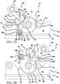
- the seat assembly 10 further includes a detent assembly 48 operatively coupled to the seat base 24 and arranged for selectively engaging and coupling with the intermediate link 44B of the linkage assembly 22.
- the detent assembly 48 is actuatable between a use condition, as shown in Figures 5A, 5B , 8 , and 9A , for operatively coupling the intermediate link 44B and the detent assembly 48, and an override condition, as shown in Figure 9C , for decoupling the intermediate link 44B and the detent assembly 48, thereby allowing pivoting of the intermediate link 44B and the linkage assembly 22 independently of the detent assembly 48.
- detent assembly 48 as shown in the Figures is arranged to selectively engage the intermediate link 44B, it is to be appreciated that the detent assembly 48 can alternatively be adapted and arranged to selectively engage any of the links 44A, 44B, 44C in the linkage assembly 22 depending on the number and configuration of links necessary for the particular seating environment, as described above, without varying the scope of the invention.
- the intermediate links 44B extend between a first end 50 and an opposite second end 52.
- Each of the intermediate links 44B further has an outward-facing lateral side 54 and an inward-facing medial side 56 extending between a front edge 58 and a rear edge 60.
- the lateral side 54 of each intermediate link 44B at the first end 50 thereof is rotatably coupled to the seat cushion 12, and the lateral side 54 of each intermediate link 44B at the second end 52 thereof is rotatably coupled to the inward-facing side 34 of the respective outer wall 30 on the seat base 24.
- a support bar 62 extends between the second ends 52 of the intermediate links 44B to ensure that the intermediate links 44B positioned adjacent to each lateral side 18 of the seat cushion 12 pivot in tandem during movement of the seat assembly 10. Additionally, a pin 64 extends outwardly from the lateral side 54 of at least one of the intermediate links 44B for selective engagement by the detent assembly 48, the pin 64 positioned generally equidistant between the first and second ends 50, 52 thereof.
- the detent assembly 48 includes a sector gear 66 rotatably coupled to the outward-facing side 36 of the outer wall 30 adj acent to the intermediate link 44B having the pin 64 extending therefrom.
- the sector gear 66 includes a toothed portion 68 opposite a non-toothed portion 70.
- the toothed portion 68 has a plurality of teeth 72 extending radially outward therefrom, and the non-toothed portion 70 includes a post 74 spaced radially apart from a curved projection 76.
- the post 74 extends axially outward from the sector gear 66 and terminates at an outer end 78 having a channel 80 extending therethrough.
- the curved projection 76 extends radially outward from the sector gear and terminates at an end portion 82 extending axially inward therefrom.
- the end portion 82 of the curved projection 76 is positioned adjacent to the rear edge 60 of the intermediate link 44B for engaging and pushing the intermediate link 44B in the first direction during rotation of the detent assembly 48 in the first direction when the seat assembly 10 is moving from the design position to the pitch position, as shown in Figures 5A and 5B .
- the detent assembly 48 further includes a hook element 84 pivotally coupled to the sector gear 66 for selectively coupling the detent assembly 48 to the intermediate link 44B, as shown in Figures 8 and 11 .
- the hook element 84 extends between a first end 86A having a rearwardly-extending hook 86B and a second end 88A having a first aperture 88B, the first aperture 88B adapted for receiving the post 74 extending from the sector gear 66 to pivotally couple the hook element 84 to the sector gear 66.
- the hook element 84 is pivotable between an engaged position wherein the hook 86B is engaged with the pin 64 extending from the intermediate link 44B, as shown in Figure 9A , to actuate the detent assembly 48 to the use condition, and a disengaged position wherein the hook 86B is disengaged with and spaced from the pin 64 extending from the intermediate link 44B to actuate the detent assembly 48 to the override condition, as shown in Figure 9C .
- the hook 86B of the hook element 84 is further adapted for pushing the intermediate link 44B in the second direction during rotation of the detent assembly 48 in the second direction when the seat assembly 10 is moving from the pitch position back to the design position.
- a biasing element 90 such as a torsion spring, is operatively coupled between the channel 80 in the post 74 and a second aperture 92 positioned substantially equidistant between the ends 86A, 88A of the hook element 84.
- the biasing element 90 has a biasing force for biasing the hook element 84 to the engaged position where the hook 86B is engaged with the pin 64 extending from the intermediate link 44B, thereby retaining the detent assembly 48 in the use condition.
- the seat assembly 10 further includes a conventional linkage motor 94 for pivoting the intermediate link 44B of the linkage assembly 22 to move the seat assembly 10 between the design position and the pitch position during normal operation thereof.
- the linkage motor 94 is mounted to the seat base 24 generally in front of the detent assembly 48.
- the linkage motor 94 further includes a pinion gear 96 arranged such that teeth 98 extending radially outward from the pinion gear 96 meshingly engage the teeth 72 extending from the sector gear 66 for selective rotation thereof, as shown in Figures 5A, 5B , and 8 .
- Actuation of the linkage motor 94 drives the pinion gear 96 for correspondingly rotating the sector gear 66 of the detent assembly 48 in the first or second direction, thereby correspondingly pivoting the intermediate link 44B in the first or second direction as described above to move the seat assembly 10 between the design position and the pitch position.
- the seat assembly 10 may further include a control unit operatively coupled to the linkage motor 94 to determine when to stop the linkage motor 94 for correctly positioning the seat assembly 10 in the design position or the pitch position.
- any alternative means of determining when to stop pivoting of the intermediate link 44B and the linkage assembly 22 for positioning the seat assembly 10 in a desired seating position may be used without varying the scope of the invention.
- actuation of the linkage motor 94 for rotating the pinion gear 96 requires a power source, which is typically supplied by the automotive vehicle. Otherwise, the pinion gear 96 is held in its current position, engaged with the sector gear 66, and is unable to rotate. Therefore, when power to the seat assembly 10 and linkage motor 94 is interrupted, such as during an accident involving the vehicle, the linkage motor 94 prevents rotation of the detent assembly 48, which prevents pivoting of the intermediate link 44B and effectively locks the seat assembly 10 in whichever position the seat assembly 10 was disposed before the loss of power.
- the seat assembly 10 If the seat assembly 10 is disposed in the design position when power is lost, it may be necessary for an occupant to move the seat assembly 10 to the pitch position for increased occupant egress space behind the seat assembly 10 so the occupant can more easily exit the vehicle. In such a situation, actuating the detent assembly 48 from the use condition to the override condition decouples the intermediate link 44B from the detent assembly 48 and the linkage motor 94. The occupant is then able to manually pivot the intermediate link 44B in the first direction independently from the detent assembly 48 and linkage motor 94, as shown in Figure 9C , by pushing forwardly on any suitable structure of the seat assembly 10, such as the seat back 20, for moving the seat assembly 10 from the design position to the pitch position without actuating the linkage motor 94.
- the detent assembly 48 is actuated from the use condition to the override condition during manual movement of the intermediate link 44B in the first direction after a loss of power to the seat assembly 10.
- the occupant first actuates the pull strap 49, shown in Figures 6 and 7 , to manually release and unlock the latching mechanisms 43 from the respective strikers 45 on the seat base 24. Due to the loss of power, the pinion gear 96 is engaged with the sector gear 66, effectively locking the sector gear 66 and preventing the detent assembly 48 from rotating, as described in further detail above.
- the contact surface on the hook 86B of the hook element 84 is non-cinching, so the pin 64 is able to move relative to the hook 86B.
- the pin 64 continues to pivot the hook element 84 from the engaged position to the disengaged position, as shown in Figures 9B and 9C , thereby actuating the detent assembly 48 from the use condition to the override condition.
- the pin 64 is spaced from the hook 86B of the hook element 84, and the intermediate link 44B is decoupled from the detent assembly 48 and the linkage motor 94.
- the intermediate link 44B is free to continue pivoting in the first direction, shown in Figure 9C , as the occupant continues to push on the suitable structure of the seat assembly 10. Continued manual pivoting of the intermediate link 44B in the first direction moves the seat assembly 10 from the design position to the pitch position, giving the occupant increased egress space behind the seat assembly 10 to more easily exit the vehicle.
- FIG. 12A-12C and 13 A second embodiment of the seat assembly 10' is shown in Figures 12A-12C and 13 , wherein like elements of the second embodiment include primed like element numbers and, as the elements are substantially similar, will not be further explained herein.
- the detent assembly 48' is actuated from the use condition to the override condition in coordination with actuation of the pull strap 49' of the cable assembly 46'.
- the cable assembly 46' further includes an additional line 100 for simultaneously pivoting the hook element 84' from the engaged position to the disengaged position.
- a distal portion 104 of the additional line 100 extends through a post 102 extending upwardly from the seat base 24' and is operatively coupled to the hook element 84' adjacent to the first end 86A' thereof. Therefore, in addition to unlocking the latching mechanisms 43', actuating the pull strap 49' also pivots the hook element 84' from the engaged position to the disengaged position, as shown in Figure 12A and 12B , thereby actuating the detent assembly 48' from the use condition to the override condition.
- the user when power to the linkage motor 94' is lost and the user needs to exit the vehicle, the user first actuates the pull strap 49', shown in Figures 7 and 13 . Actuation of the pull strap 49' manually releases and unlocks the latching mechanisms 43' from the respective strikers 45' on the seat base 24'. Actuation of the pull strap 49' also manually pivots the hook element 84' from the engaged position with the pin 64' extending from the intermediate link 44B', as shown in Figure 12A , to the disengaged position spaced from the pin 64', as shown in Figure 12B , thereby actuating the detent assembly 48' from the use condition to the override condition.
- the intermediate link 44B' is decoupled from the detent assembly 48' and the linkage motor 94'.
- the intermediate link 44B' is therefore free to pivot in the first direction, shown in Figure 12C , as the occupant pushes on the suitable structure of the seat assembly 10', such as the seat back 20'.
- the intermediate link 44B' moves the seat assembly 10' from the design position to the pitch position, giving the occupant increased egress space behind the seat assembly 10' to more easily exit the vehicle.
Landscapes
- Engineering & Computer Science (AREA)
- Aviation & Aerospace Engineering (AREA)
- Transportation (AREA)
- Mechanical Engineering (AREA)
- Seats For Vehicles (AREA)
Claims (15)
- Sitzanordnung (10) zur Verwendung in einem Kraftfahrzeug, wobei die Sitzanordnung (10) umfasst:ein Sitzpolster (12) zum Stützen eines Insassen in dem Kraftfahrzeug und eine Sitzlehne (20), die schwenkbar mit dem Sitzpolster (12) verbunden ist,eine Sitzbasis (24), die zur Befestigung der Sitzanordnung (10) in dem Kraftfahrzeug geeignet ist,mindestens eine Verbindung (22, 44A, 44B, 44C), die schwenkbar zwischen dem Sitzpolster (12) und der Sitzbasis (24) gekoppelt ist, wobei das Schwenken des der mindestens einen Verbindung (22, 44A, 44B, 44C) die Sitzanordnung (10) zwischen mindestens einer Konstruktionsposition und einer Neigungsposition bewegt,eine Arretierungsanordnung (48), die drehbar mit der Sitzbasis (24) gekoppelt ist, wobei die Arretierungsanordnung (48) zwischen einem Gebrauchszustand zum betriebsmäßigen Koppeln der mindestens einen Verbindung (22, 44A, 44B, 44C) und der Arretierungsanordnung (48) und einem Überbrückungszustand zum Entkoppeln die mindestens einen Verbindung (22, 44A, 44B, 44C) und der Arretierungsanordnung (48) betätigbar ist, undeinen Verbindungsmotor (94), der funktionsmäßig mit der Arretierungsanordnung (48) in Eingriff steht, um die mindestens eine Verbindung (22, 44A, 44B, 44C) zu schwenken, um die Sitzanordnung (10) zwischen der Konstruktionsposition und der Neigungsposition zu bewegen,wobei das Betätigen der Arretierungsanordnung (48) aus dem Gebrauchszustand in den Überbrückungszustand ein manuelles Schwenken der mindestens einen Verbindung (22, 44A, 44B, 44C) ermöglicht, um die Sitzanordnung (10) unabhängig von der Arretierungsanordnung (48) und ohne Verwendung des Verbindungsmotors (94) zwischen der Konstruktionsposition und der Neigungsposition zu bewegen.
- Sitzanordnung (10) nach Anspruch 1, wobei die Arretierungsanordnung (48) ein Sektorrad (66) umfasst, das drehbar mit der Sitzbasis (24) gekoppelt ist und mit dem Verbindungsmotor (94) in Eingriff steht.
- Sitzanordnung (10) nach Anspruch 2, wobei die Arretierungsanordnung (48) ferner ein Hakenelement (84) aufweist, das schwenkbar mit dem Sektorrad (66) verbunden ist, wobei das Hakenelement (84) zwischen einer Eingriffsposition mit der mindestens einen Verbindung (22, 44A, 44B, 44C) zur Betätigung der Arretierungsanordnung (48) in den Gebrauchszustand und einer Außereingriffsposition mit der mindestens einen Verbindung (22, 44A, 44B, 44C) zur Betätigung der Arretierungsanordnung (48) in den Überbrückungszustand betätigt werden kann.
- Sitzanordnung (10) nach Anspruch 3 mit ferner mindestens einem Verriegelungsmechanismus (43), der sich vom Sitzpolster (12) aus erstreckt, um abnehmbar mit der Sitzbasis (24) verbunden zu werden, um die Sitzanordnung (10) selektiv zu verriegeln und zu entriegeln, wodurch die Bewegung der Sitzanordnung (10) aus der Konstruktionsposition in die Neigungsposition selektiv verhindert und ermöglicht wird.
- Sitzanordnung (10) nach Anspruch 4 mit ferner einer Seilanordnung (46), die funktionell mit dem mindestens einen Verriegelungsmechanismus (43) gekoppelt ist, wobei die Betätigung der Seilanordnung (46) den mindestens einen Verriegelungsmechanismus (43) betätigt, um die Sitzanordnung (10) zu entriegeln, wodurch die Bewegung der Sitzanordnung (10) von der Konstruktionsposition in die Neigungsposition ermöglicht wird.
- Sitzanordnung (10) nach Anspruch 5, wobei ein Vorwärtsschieben auf die Sitzanordnung (10), wenn die Sitzanordnung (10) entriegelt ist, das Hakenelement (84) aus der Eingriffsposition in die Außereingriffsposition schwenkt, um die Arretierungsanordnung (48) aus dem Gebrauchszustand in den Überbrückungszustand zu bringen.
- Sitzanordnung (10) nach Anspruch 5, wobei die Seilanordnung (46) ferner mit dem Hakenelement (84) funktionsfähig gekoppelt ist und die Betätigung der Seilanordnung (46) auch das Hakenelement (84) aus der Eingriffsposition in die Außereingriffsposition schwenkt, um die Arretierungsanordnung (48) aus dem Gebrauchszustand in den Überbrückungszustand zu betätigen.
- Sitzanordnung (10) nach Anspruch 6, wobei die Arretierungsanordnung (48) ferner ein Vorspannelement (90) umfasst, das funktionell zwischen dem Hakenelement (84) und dem Sektorrad (66) gekoppelt ist, um das Hakenelement (84) in die Eingriffsposition vorzuspannen, um die Arretierungsanordnung (48) in der Gebrauchsstellung zu halten.
- Sitzanordnung (10) nach Anspruch 8, wobei die mindestens eine Verbindung (22, 44A, 44B, 44C) einen Stift (64) aufweist, der sich seitlich davon erstreckt, wobei das Hakenelement (84) der Arretierungsanordnung (48) mit dem Stift (64) in Eingriff steht, wenn es sich in der Eingriffsstellung befindet, und das Hakenelement (84) der Arretierungsanordnung (48) mit dem Stift (64) außer Eingriff steht, wenn es sich in der Außereingriffsstellung befindet.
- Sitzanordnung (10) nach Anspruch 9 mit ferner einem Zugriemen (49), der funktionell mit der Seilanordnung (46) gekoppelt ist, wobei das Ziehen des Zugriemens (49) die Seilanordnung (46) betätigt, um die Sitzanordnung (10) zu entriegeln und die Bewegung der Sitzanordnung (10) von der Konstruktionsposition in die Neigungsposition zu ermöglichen.
- Sitzanordnung (10) nach Anspruch 10, wobei der Verbindungsmotor (94) ferner ein Ritzel (96) aufweist, das betriebsmäßig mit dem Sektorrad (66) der Arretierungsanordnung (48) gekoppelt ist, wobei der Verbindungsmotor (94) das Ritzel (96) selektiv antreibt, um das Sektorrad (66) zu drehen, um die mindestens eine Verbindung (22, 44A, 44B, 44C) zu schwenken.
- Sitzanordnung (10) nach Anspruch 11, wobei das Sektorrad (66) ferner einen Pfosten (102) zur Aufnahme des Hakenelements (84) aufweist, um das Hakenelement (84) schwenkbar mit dem Sektorrad (66) zu verbinden.
- Sitzanordnung (10) nach Anspruch 12, wobei das Sektorrad (66) ferner einen Vorsprung (76) aufweist, der sich neben dem Hakenelement (84) erstreckt und so angeordnet ist, dass er während der Drehung des Sektorrads (66) selektiv in die mindestens eine Verbindung (22, 44A, 44B, 44C) eingreift und diese schiebt.
- Sitzanordnung (10) nach Anspruch 13 mit ferner einer Sitzschienenbaugruppe (38), die fest mit der Sitzbasis (24) verbunden ist, um eine Vor- und Rückwärtsbewegung der Sitzanordnung (10) innerhalb des Kraftfahrzeugs zu ermöglichen.
- Sitzanordnung (10) nach Anspruch 14, wobei die mindestens eine Verbindung (22, 44A, 44B, 44C) ein vorderes Verbindungsglied (44A), ein Zwischenglied (44B) und ein hinteres Verbindungsglied (44C) umfasst, wobei das vordere, das hintere und das Zwischenglied (44A, 44B, 44C) jeweils schwenkbar zwischen dem Sitzpolster (12) und der Sitzbasis (24) gekoppelt sind, um die Sitzanordnung (10) zwischen der Konstruktionsposition und der Neigungsposition zu bewegen,wobei vorzugsweise die Arretierungsanordnung (48) drehbar mit der Sitzbasis (24) gekoppelt ist, um selektiv in das Zwischenglied (44B) einzugreifen, oderwobei die mindestens eine Verbindung (22, 44A, 44B, 44C) ein vorderes Verbindungsglied (44A) und ein hinteres Verbindungsglied (44C) umfasst, um ein Viergelenkgestänge (22) zu bilden, wobei das vordere und das hintere Verbindungsglied (44A, 44C) jeweils schwenkbar zwischen dem Sitzpolster (12) und der Sitzbasis (24) gekoppelt sind, um die Sitzanordnung (10) zwischen der Konstruktionsposition und der Neigungsposition zu bewegen.
Applications Claiming Priority (2)
| Application Number | Priority Date | Filing Date | Title |
|---|---|---|---|
| US202062705392P | 2020-06-25 | 2020-06-25 | |
| PCT/US2021/039086 WO2021263103A1 (en) | 2020-06-25 | 2021-06-25 | Seat assembly with override condition |
Publications (2)
| Publication Number | Publication Date |
|---|---|
| EP4126589A1 EP4126589A1 (de) | 2023-02-08 |
| EP4126589B1 true EP4126589B1 (de) | 2024-01-31 |
Family
ID=77071741
Family Applications (1)
| Application Number | Title | Priority Date | Filing Date |
|---|---|---|---|
| EP21746603.6A Active EP4126589B1 (de) | 2020-06-25 | 2021-06-25 | Sitzanordnung mit übersteuerungsbedingung |
Country Status (5)
| Country | Link |
|---|---|
| US (1) | US20230249586A1 (de) |
| EP (1) | EP4126589B1 (de) |
| CN (1) | CN115916585A (de) |
| CA (1) | CA3182999A1 (de) |
| WO (1) | WO2021263103A1 (de) |
Family Cites Families (5)
| Publication number | Priority date | Publication date | Assignee | Title |
|---|---|---|---|---|
| EP1882609A1 (de) * | 2006-07-27 | 2008-01-30 | C.R.F. Società Consortile per Azioni | Sitzanordnung mit einer Viergelenk-Abstützeinrichtung für ein Kraftfahrzeug |
| US10442322B2 (en) * | 2017-11-17 | 2019-10-15 | Brose Fahrzeugteile Gmbh & Co. Kommanditgesellschaft | Easy-entry vehicle seat |
| FR3086599B1 (fr) * | 2018-09-27 | 2020-09-25 | Faurecia Sieges Dautomobile | Systeme comprenant un siege de vehicule a dossier inclinable |
| FR3086598B1 (fr) * | 2018-10-02 | 2021-05-28 | Faurecia Sieges Dautomobile | Siege de vehicule |
| CN113260530B (zh) | 2018-12-19 | 2023-06-27 | 麦格纳座椅公司 | 在机动车辆中使用的用于在多个位置之间移动的座椅组件 |
-
2021
- 2021-06-25 US US18/003,328 patent/US20230249586A1/en active Pending
- 2021-06-25 CN CN202180044596.3A patent/CN115916585A/zh active Pending
- 2021-06-25 WO PCT/US2021/039086 patent/WO2021263103A1/en unknown
- 2021-06-25 CA CA3182999A patent/CA3182999A1/en active Pending
- 2021-06-25 EP EP21746603.6A patent/EP4126589B1/de active Active
Also Published As
| Publication number | Publication date |
|---|---|
| CN115916585A (zh) | 2023-04-04 |
| CA3182999A1 (en) | 2021-12-30 |
| EP4126589A1 (de) | 2023-02-08 |
| US20230249586A1 (en) | 2023-08-10 |
| WO2021263103A1 (en) | 2021-12-30 |
Similar Documents
| Publication | Publication Date | Title |
|---|---|---|
| EP1049602B1 (de) | Drehgelenkmechanismus für multifunktionelle anwendungen an einem kraftfahrzeugsitz | |
| US6250704B1 (en) | Release mechanism for fold and flip seat assembly | |
| EP2571718B1 (de) | Leicht zugängliches sitzsystem mit einzelpositionsspeicher und offenhaltungsfunktion | |
| US8016354B2 (en) | Vehicle seat assembly with stand up position | |
| US9327620B2 (en) | Vehicle seat assembly with easy-entry mechanism | |
| US8167372B2 (en) | Seat assembly having dual actuated locking mechanism | |
| EP1601549B1 (de) | Sitzvorrichtung mit rücklehnenverriegelung | |
| EP1606137B1 (de) | Rückenlehnenneigungsverstellvorrichtung für fahrzeuge | |
| JP2001171407A (ja) | 平坦折り畳み式車両シート | |
| WO2007112586A1 (en) | Stand up seat | |
| WO2011063528A1 (en) | Recliner assembly walk-in actuator | |
| CA2951080A1 (en) | Seat assembly with recliner lockout mechanism | |
| EP4065412B1 (de) | Sitzanordnung mit leichtem energieeintritt und konzentrischer bewegung | |
| US9296318B2 (en) | Vehicle seat | |
| EP1904332B1 (de) | Festschnallen/verriegeln eines schenkels zur gewährleistung von eingriff | |
| EP4126589B1 (de) | Sitzanordnung mit übersteuerungsbedingung | |
| US20070252401A1 (en) | Rear baggage compartment structure of vehicle | |
| CN111954608A (zh) | 具有互锁的内部完全记忆座椅轨道 | |
| EP4037932B1 (de) | Sitzanordnung mit rücklaufsperrelement | |
| JPH0233528B2 (ja) | Jidoshanoshiitosochi | |
| US11772524B2 (en) | Vehicle seat | |
| EP1241044B1 (de) | Sitzstruktur für ein Fahrzeug | |
| WO2020018987A1 (en) | Power drive coupling mechanism | |
| JPH02293225A (ja) | シートトラックスライド装置におけるメモリ付きロック機構 |
Legal Events
| Date | Code | Title | Description |
|---|---|---|---|
| STAA | Information on the status of an ep patent application or granted ep patent |
Free format text: STATUS: UNKNOWN |
|
| STAA | Information on the status of an ep patent application or granted ep patent |
Free format text: STATUS: THE INTERNATIONAL PUBLICATION HAS BEEN MADE |
|
| PUAI | Public reference made under article 153(3) epc to a published international application that has entered the european phase |
Free format text: ORIGINAL CODE: 0009012 |
|
| STAA | Information on the status of an ep patent application or granted ep patent |
Free format text: STATUS: REQUEST FOR EXAMINATION WAS MADE |
|
| 17P | Request for examination filed |
Effective date: 20221026 |
|
| AK | Designated contracting states |
Kind code of ref document: A1 Designated state(s): AL AT BE BG CH CY CZ DE DK EE ES FI FR GB GR HR HU IE IS IT LI LT LU LV MC MK MT NL NO PL PT RO RS SE SI SK SM TR |
|
| P01 | Opt-out of the competence of the unified patent court (upc) registered |
Effective date: 20230517 |
|
| GRAP | Despatch of communication of intention to grant a patent |
Free format text: ORIGINAL CODE: EPIDOSNIGR1 |
|
| STAA | Information on the status of an ep patent application or granted ep patent |
Free format text: STATUS: GRANT OF PATENT IS INTENDED |
|
| DAV | Request for validation of the european patent (deleted) | ||
| DAX | Request for extension of the european patent (deleted) | ||
| INTG | Intention to grant announced |
Effective date: 20230906 |
|
| GRAS | Grant fee paid |
Free format text: ORIGINAL CODE: EPIDOSNIGR3 |
|
| GRAA | (expected) grant |
Free format text: ORIGINAL CODE: 0009210 |
|
| STAA | Information on the status of an ep patent application or granted ep patent |
Free format text: STATUS: THE PATENT HAS BEEN GRANTED |
|
| AK | Designated contracting states |
Kind code of ref document: B1 Designated state(s): AL AT BE BG CH CY CZ DE DK EE ES FI FR GB GR HR HU IE IS IT LI LT LU LV MC MK MT NL NO PL PT RO RS SE SI SK SM TR |
|
| REG | Reference to a national code |
Ref country code: GB Ref legal event code: FG4D Ref country code: CH Ref legal event code: EP |
|
| REG | Reference to a national code |
Ref country code: DE Ref legal event code: R096 Ref document number: 602021009070 Country of ref document: DE |
|
| REG | Reference to a national code |
Ref country code: IE Ref legal event code: FG4D |
|
| REG | Reference to a national code |
Ref country code: LT Ref legal event code: MG9D |