EP4126589B1 - Seat assembly with override condition - Google Patents
Seat assembly with override condition Download PDFInfo
- Publication number
- EP4126589B1 EP4126589B1 EP21746603.6A EP21746603A EP4126589B1 EP 4126589 B1 EP4126589 B1 EP 4126589B1 EP 21746603 A EP21746603 A EP 21746603A EP 4126589 B1 EP4126589 B1 EP 4126589B1
- Authority
- EP
- European Patent Office
- Prior art keywords
- assembly
- seat
- seat assembly
- link
- detent
- Prior art date
- Legal status (The legal status is an assumption and is not a legal conclusion. Google has not performed a legal analysis and makes no representation as to the accuracy of the status listed.)
- Active
Links
- 230000007246 mechanism Effects 0.000 claims description 11
- 230000008878 coupling Effects 0.000 claims description 8
- 238000010168 coupling process Methods 0.000 claims description 8
- 238000005859 coupling reaction Methods 0.000 claims description 8
- 230000000712 assembly Effects 0.000 description 3
- 238000000429 assembly Methods 0.000 description 3
Images


Classifications
-
- B—PERFORMING OPERATIONS; TRANSPORTING
- B60—VEHICLES IN GENERAL
- B60N—SEATS SPECIALLY ADAPTED FOR VEHICLES; VEHICLE PASSENGER ACCOMMODATION NOT OTHERWISE PROVIDED FOR
- B60N2/00—Seats specially adapted for vehicles; Arrangement or mounting of seats in vehicles
- B60N2/02—Seats specially adapted for vehicles; Arrangement or mounting of seats in vehicles the seat or part thereof being movable, e.g. adjustable
- B60N2/0224—Non-manual adjustments, e.g. with electrical operation
- B60N2/02246—Electric motors therefor
-
- B—PERFORMING OPERATIONS; TRANSPORTING
- B60—VEHICLES IN GENERAL
- B60N—SEATS SPECIALLY ADAPTED FOR VEHICLES; VEHICLE PASSENGER ACCOMMODATION NOT OTHERWISE PROVIDED FOR
- B60N2/00—Seats specially adapted for vehicles; Arrangement or mounting of seats in vehicles
- B60N2/24—Seats specially adapted for vehicles; Arrangement or mounting of seats in vehicles for particular purposes or particular vehicles
- B60N2/30—Non-dismountable or dismountable seats storable in a non-use position, e.g. foldable spare seats
- B60N2/3002—Non-dismountable or dismountable seats storable in a non-use position, e.g. foldable spare seats back-rest movements
- B60N2/3004—Non-dismountable or dismountable seats storable in a non-use position, e.g. foldable spare seats back-rest movements by rotation only
- B60N2/3009—Non-dismountable or dismountable seats storable in a non-use position, e.g. foldable spare seats back-rest movements by rotation only about transversal axis
- B60N2/3011—Non-dismountable or dismountable seats storable in a non-use position, e.g. foldable spare seats back-rest movements by rotation only about transversal axis the back-rest being hinged on the cushion, e.g. "portefeuille movement"
-
- B—PERFORMING OPERATIONS; TRANSPORTING
- B60—VEHICLES IN GENERAL
- B60N—SEATS SPECIALLY ADAPTED FOR VEHICLES; VEHICLE PASSENGER ACCOMMODATION NOT OTHERWISE PROVIDED FOR
- B60N2/00—Seats specially adapted for vehicles; Arrangement or mounting of seats in vehicles
- B60N2/02—Seats specially adapted for vehicles; Arrangement or mounting of seats in vehicles the seat or part thereof being movable, e.g. adjustable
- B60N2/0224—Non-manual adjustments, e.g. with electrical operation
- B60N2/02246—Electric motors therefor
- B60N2/02253—Electric motors therefor characterised by the transmission between the electric motor and the seat or seat parts
-
- B—PERFORMING OPERATIONS; TRANSPORTING
- B60—VEHICLES IN GENERAL
- B60N—SEATS SPECIALLY ADAPTED FOR VEHICLES; VEHICLE PASSENGER ACCOMMODATION NOT OTHERWISE PROVIDED FOR
- B60N2/00—Seats specially adapted for vehicles; Arrangement or mounting of seats in vehicles
- B60N2/02—Seats specially adapted for vehicles; Arrangement or mounting of seats in vehicles the seat or part thereof being movable, e.g. adjustable
- B60N2/04—Seats specially adapted for vehicles; Arrangement or mounting of seats in vehicles the seat or part thereof being movable, e.g. adjustable the whole seat being movable
- B60N2/045—Longitudinal adjustment by means of articulated rods supporting the seat, e.g. parallelogram mechanisms
-
- B—PERFORMING OPERATIONS; TRANSPORTING
- B60—VEHICLES IN GENERAL
- B60N—SEATS SPECIALLY ADAPTED FOR VEHICLES; VEHICLE PASSENGER ACCOMMODATION NOT OTHERWISE PROVIDED FOR
- B60N2/00—Seats specially adapted for vehicles; Arrangement or mounting of seats in vehicles
- B60N2/02—Seats specially adapted for vehicles; Arrangement or mounting of seats in vehicles the seat or part thereof being movable, e.g. adjustable
- B60N2/04—Seats specially adapted for vehicles; Arrangement or mounting of seats in vehicles the seat or part thereof being movable, e.g. adjustable the whole seat being movable
- B60N2/12—Seats specially adapted for vehicles; Arrangement or mounting of seats in vehicles the seat or part thereof being movable, e.g. adjustable the whole seat being movable slidable and tiltable
-
- B—PERFORMING OPERATIONS; TRANSPORTING
- B60—VEHICLES IN GENERAL
- B60N—SEATS SPECIALLY ADAPTED FOR VEHICLES; VEHICLE PASSENGER ACCOMMODATION NOT OTHERWISE PROVIDED FOR
- B60N2/00—Seats specially adapted for vehicles; Arrangement or mounting of seats in vehicles
- B60N2/02—Seats specially adapted for vehicles; Arrangement or mounting of seats in vehicles the seat or part thereof being movable, e.g. adjustable
- B60N2/20—Seats specially adapted for vehicles; Arrangement or mounting of seats in vehicles the seat or part thereof being movable, e.g. adjustable the back-rest being tiltable, e.g. to permit easy access
- B60N2/206—Seats specially adapted for vehicles; Arrangement or mounting of seats in vehicles the seat or part thereof being movable, e.g. adjustable the back-rest being tiltable, e.g. to permit easy access to a position in which it can be used as a support for objects, e.g. as a tray
-
- B—PERFORMING OPERATIONS; TRANSPORTING
- B60—VEHICLES IN GENERAL
- B60N—SEATS SPECIALLY ADAPTED FOR VEHICLES; VEHICLE PASSENGER ACCOMMODATION NOT OTHERWISE PROVIDED FOR
- B60N2/00—Seats specially adapted for vehicles; Arrangement or mounting of seats in vehicles
- B60N2/02—Seats specially adapted for vehicles; Arrangement or mounting of seats in vehicles the seat or part thereof being movable, e.g. adjustable
- B60N2/22—Seats specially adapted for vehicles; Arrangement or mounting of seats in vehicles the seat or part thereof being movable, e.g. adjustable the back-rest being adjustable
- B60N2/2213—Gear wheel driven mechanism
-
- B—PERFORMING OPERATIONS; TRANSPORTING
- B60—VEHICLES IN GENERAL
- B60N—SEATS SPECIALLY ADAPTED FOR VEHICLES; VEHICLE PASSENGER ACCOMMODATION NOT OTHERWISE PROVIDED FOR
- B60N2/00—Seats specially adapted for vehicles; Arrangement or mounting of seats in vehicles
- B60N2/24—Seats specially adapted for vehicles; Arrangement or mounting of seats in vehicles for particular purposes or particular vehicles
- B60N2/30—Non-dismountable or dismountable seats storable in a non-use position, e.g. foldable spare seats
- B60N2/3038—Cushion movements
- B60N2/304—Cushion movements by rotation only
- B60N2/3045—Cushion movements by rotation only about transversal axis
- B60N2/305—Cushion movements by rotation only about transversal axis the cushion being hinged on the vehicle frame
-
- B—PERFORMING OPERATIONS; TRANSPORTING
- B60—VEHICLES IN GENERAL
- B60N—SEATS SPECIALLY ADAPTED FOR VEHICLES; VEHICLE PASSENGER ACCOMMODATION NOT OTHERWISE PROVIDED FOR
- B60N2/00—Seats specially adapted for vehicles; Arrangement or mounting of seats in vehicles
- B60N2/90—Details or parts not otherwise provided for
- B60N2/919—Positioning and locking mechanisms
- B60N2002/952—Positioning and locking mechanisms characterised by details of the locking system
- B60N2002/957—Positioning and locking mechanisms characterised by details of the locking system the locking system prevents an abnormal or wrong mounting situation, i.e. deployment or functioning of a seat part being prevented if the seat or seat part is not properly mounted
Description
- This application claims priority to and all the benefits of
U.S. Provisional Application 62/705,392, filed on June 25, 2020 - The present invention relates to a seat assembly for use in an automotive vehicle.
- Seat assemblies for use in an automotive vehicle are known in the art (see i.e.
FR-A-3086599 - The seat assembly according to the invention comprises the features of claim 1.
- According to the invention, a seat assembly is provided for use in an automotive vehicle. The seat assembly includes a seat cushion for supporting an occupant in the automotive vehicle and a seat back pivotally coupled to the seat cushion. The seat assembly further includes a seat base adapted for mounting the seat assembly within the automotive vehicle. At least one link is pivotally coupled between the seat cushion and the seat base, and pivoting of the at least one link moves the seat assembly between a design position and a pitch position. A detent assembly is rotatably coupled to the seat base, and the detent assembly is actuatable between a use condition for operatively coupling the at least one link and the detent assembly, and an override condition for decoupling the at least one link and the detent assembly. A linkage motor is operatively engaged with the detent assembly for pivoting the at least one link to move the seat assembly between the design position and the pitch position. Actuation of the detent assembly from the use condition to the override condition allows for manual pivoting of the at least one link to move the seat assembly between the design position and the pitch position independently of the detent assembly and without actuation of the linkage motor.
- Advantages of the present disclosure will be readily appreciated as the same becomes better understood by reference to the following detailed description when considered in connection with the accompanying drawings, wherein:
-
Figure 1 is a perspective view of a seat assembly for use in an automotive vehicle according to a first embodiment of the present invention showing the seat assembly in a design position; -
Figure 2 is a perspective view of the seat assembly ofFigure 1 showing the seat assembly in a pitch position; -
Figure 3 is a fragmentary side view of the seat assembly ofFigure 1 further showing the seat assembly in the design position; -
Figure 4 is a fragmentary side view of the seat assembly ofFigure 1 further showing the seat assembly in the pitch position; -
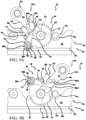
Figure 5A is an enlarged fragmentary side view of the seat assembly ofFigure 1 showing one of a pair of intermediate links and a detent assembly each coupled to a seat base; -
Figure 5B is an enlarged fragmentary side view of the seat assembly ofFigure 1 showing one of the pair of intermediate links and the detent assembly rotating in a first direction; -
Figure 6 is a fragmentary top view of a cable assembly of the seat assembly ofFigure 1 ; -
Figure 7 is an enlarged fragmentary perspective view of the seat assembly ofFigure 1 showing a pull strap operatively coupled to a rear portion of a seat cushion; -
Figure 8 is an enlarged fragmentary perspective view of the seat assembly ofFigure 1 showing a hook element pivotally coupled to a sector gear of the detent assembly; -
Figure 9A is an enlarged fragmentary side view of the seat assembly ofFigure 1 showing the detent assembly in a use condition; -
Figure 9B is an enlarged fragmentary side view of the seat assembly ofFigure 1 showing the detent assembly disposed between the use condition and an override condition; -
Figure 9C is an enlarged fragmentary side view of the seat assembly ofFigure 1 showing the detent assembly in the override condition; -
Figure 10 is an enlarged fragmentary perspective view of the pair of intermediate links of the seat assembly ofFigure 1 ; -
Figure 11 is an enlarged fragmentary perspective view of the detent assembly of the seat assembly ofFigure 1 ; -
Figure 12A is an enlarged fragmentary side view of a seat assembly according to a second embodiment of the present invention showing a detent assembly in a use condition; -
Figure 12B is an enlarged fragmentary side view of the seat assembly ofFigure 12A showing the detent assembly in an override condition; -
Figure 12C is an enlarged fragmentary side view of the seat assembly ofFigure 12A further showing the detent assembly in the override condition and one of a pair of intermediate links pivoting in a first direction; and -
Figure 13 is a fragmentary top view of a cable assembly of the seat assembly ofFigure 12A . - Referring to the Figures, wherein like numerals indicate like or corresponding parts throughout the several views, a seat assembly adapted to be mounted to a floor of an automotive vehicle for movement between a plurality of positions is shown generally at 10. The
seat assembly 10 includes aseat cushion 12 extending between afront portion 14 and arear portion 16 with opposinglateral sides 18. A seat back 20 is pivotally coupled to therear portion 16 of theseat cushion 12 for pivotal movement of the seat back 20 between a plurality of reclined positions and a folded position in which the seat back 20 overlaps theseat cushion 12. Theseat assembly 10 further includes a linkage assembly, shown generally at 22, operatively coupled between theseat cushion 12 and aseat base 24. The linkage assembly 22 is operable for moving and tilting theseat assembly 10 relative to the floor of the automotive vehicle between the plurality of positions, including a design position, as shown inFigures 1 and3 , and a pitch position, as shown inFigures 2 and4 . - Referring to
Figures 1-4 , theseat base 24 includes a pair of laterally spaced apartside sections 26, eachside section 26 positioned generally underneath one of the respectivelateral sides 18 of theseat cushion 12. Theside sections 26 may be fixedly coupled together, and eachside section 26 has a generally U-shaped cross-sectional profile defined by opposing inner andouter walls floor portion 32 extending therebetween. Theouter wall 30 on eachside section 26 has a medial, inward-facing side 34 opposite a lateral, outward-facingside 36. Theside sections 26 of theseat base 24 may be mounted directly to the floor of the automotive vehicle or fixedly coupled to aseat track assembly 38 as is known in the art for providing fore and aft movement of theseat assembly 10 within the automotive vehicle, as shown in the Figures. Theseat track assembly 38 includes a pair of slidingtracks 40 fixedly coupled to theseat base 24, thesliding tracks 40 repositionable along a pair of laterally spaced apart fixedtracks 42 mounted to the floor of the automotive vehicle. Thefloor portion 32 on eachside section 26 is secured to the respectivesliding track 40 for coupling theseat base 24 to theseat track assembly 38 and providing fore and aft sliding movement of theseat assembly 10 within the automotive vehicle. - The linkage assembly 22 in the embodiment of the
seat assembly 10 shown in the Figures includes a pair of laterally spaced apartfront links 44A, a pair of laterally spaced apartintermediate links 44B, and a pair of laterally spaced apartrear links 44C, wherein thelinks seat assembly 10 can include any number or configuration oflinks seat assembly 10 for use in a particular seating environment within a particular vehicle without varying the scope of the invention. One such alternative linkage assembly 22 is a four-bar linkage having a pair of laterally spaced apart front links and a pair of laterally spaced apart rear links as described in International PublicationWO/2020/132153 . Referring toFigures 3 and4 , each of thelinks side sections 26 of theseat base 24 and theseat cushion 12 as is known in the art. Thelinks seat assembly 10 relative to the floor of the automotive vehicle between at least the design position and the pitch position. In the design position, shown inFigures 1 and3 , theseat assembly 10 is generally spaced from the floor of the automotive vehicle to support an occupant. In the pitch position, shown inFigures 2 and4 , theseat assembly 10 tilts forwardly and downwardly toward the floor of the automotive vehicle for increased ingress and egress behind theseat assembly 10. Additional seating positions, including a stow position where theseat assembly 10 lowers toward the floor of the automotive vehicle for increased cargo room therein, are also contemplated with respect to the embodiment of theseat assembly 10 as shown in the Figures. - Pivoting the
links Figures 3-5B ) moves theseat assembly 10 from the design position to the pitch position. Conversely, pivoting of thelinks Figures 3-5B ) moves theseat assembly 10 from the pitch position back to the design position. Referring toFigures 1-4 , theseat assembly 10 further includes alatching mechanism 43 extending downwardly from therear portion 16 on eachlateral side 18 of theseat cushion 12, and astriker 45 mounted between the inner andouter walls side sections 26 of theseat base 24. The latchingmechanisms 43 are adapted and arranged for removably coupling to thestrikers 45 as is known in the art for selectively locking and preventing pivoting of thelinks seat assembly 10 in the design position as desired by the occupant. Referring toFigure 6 , a conventional cable assembly, shown generally at 46, is mounted underneath theseat cushion 12 and extends between each of the latchingmechanisms 43. Anactuator 47 is integrated into thecable assembly 46 for electromechanically actuating and selectively unlocking the latchingmechanisms 43 during normal operation of theseat assembly 10, as is known in the art. Thecable assembly 46 additionally includes apull strap 49 operatively coupled generally adjacent to therear portion 16 of theseat cushion 12 for manually actuating and unlocking the latchingmechanisms 43 during a loss of power to theseat assembly 10 and theactuator 47, as shown inFigures 6 and7 . - Referring to
Figures 3 ,8 , and9A-9C , theseat assembly 10 further includes adetent assembly 48 operatively coupled to theseat base 24 and arranged for selectively engaging and coupling with theintermediate link 44B of the linkage assembly 22. Thedetent assembly 48 is actuatable between a use condition, as shown inFigures 5A, 5B ,8 , and9A , for operatively coupling theintermediate link 44B and thedetent assembly 48, and an override condition, as shown inFigure 9C , for decoupling theintermediate link 44B and thedetent assembly 48, thereby allowing pivoting of theintermediate link 44B and the linkage assembly 22 independently of thedetent assembly 48. Although thedetent assembly 48 as shown in the Figures is arranged to selectively engage theintermediate link 44B, it is to be appreciated that thedetent assembly 48 can alternatively be adapted and arranged to selectively engage any of thelinks - Referring to
Figures 3 ,5A , and10 , theintermediate links 44B extend between afirst end 50 and an oppositesecond end 52. Each of theintermediate links 44B further has an outward-facinglateral side 54 and an inward-facing medial side 56 extending between afront edge 58 and arear edge 60. Thelateral side 54 of eachintermediate link 44B at thefirst end 50 thereof is rotatably coupled to theseat cushion 12, and thelateral side 54 of eachintermediate link 44B at thesecond end 52 thereof is rotatably coupled to the inward-facing side 34 of the respectiveouter wall 30 on theseat base 24. Referring toFigure 10 , a support bar 62 extends between the second ends 52 of theintermediate links 44B to ensure that theintermediate links 44B positioned adjacent to eachlateral side 18 of theseat cushion 12 pivot in tandem during movement of theseat assembly 10. Additionally, apin 64 extends outwardly from thelateral side 54 of at least one of theintermediate links 44B for selective engagement by thedetent assembly 48, thepin 64 positioned generally equidistant between the first and second ends 50, 52 thereof. - Referring to
Figure 8 , thedetent assembly 48 includes asector gear 66 rotatably coupled to the outward-facingside 36 of theouter wall 30 adj acent to theintermediate link 44B having thepin 64 extending therefrom. Thesector gear 66 includes atoothed portion 68 opposite anon-toothed portion 70. Thetoothed portion 68 has a plurality ofteeth 72 extending radially outward therefrom, and thenon-toothed portion 70 includes apost 74 spaced radially apart from acurved projection 76. Referring toFigure 8 and11 , thepost 74 extends axially outward from thesector gear 66 and terminates at anouter end 78 having achannel 80 extending therethrough. Thecurved projection 76 extends radially outward from the sector gear and terminates at anend portion 82 extending axially inward therefrom. Theend portion 82 of thecurved projection 76 is positioned adjacent to therear edge 60 of theintermediate link 44B for engaging and pushing theintermediate link 44B in the first direction during rotation of thedetent assembly 48 in the first direction when theseat assembly 10 is moving from the design position to the pitch position, as shown inFigures 5A and 5B . - The
detent assembly 48 further includes ahook element 84 pivotally coupled to thesector gear 66 for selectively coupling thedetent assembly 48 to theintermediate link 44B, as shown inFigures 8 and11 . Thehook element 84 extends between afirst end 86A having a rearwardly-extendinghook 86B and asecond end 88A having afirst aperture 88B, thefirst aperture 88B adapted for receiving thepost 74 extending from thesector gear 66 to pivotally couple thehook element 84 to thesector gear 66. Thehook element 84 is pivotable between an engaged position wherein thehook 86B is engaged with thepin 64 extending from theintermediate link 44B, as shown inFigure 9A , to actuate thedetent assembly 48 to the use condition, and a disengaged position wherein thehook 86B is disengaged with and spaced from thepin 64 extending from theintermediate link 44B to actuate thedetent assembly 48 to the override condition, as shown inFigure 9C . When in the engaged position, thehook 86B of thehook element 84 is further adapted for pushing theintermediate link 44B in the second direction during rotation of thedetent assembly 48 in the second direction when theseat assembly 10 is moving from the pitch position back to the design position. A biasingelement 90, such as a torsion spring, is operatively coupled between thechannel 80 in thepost 74 and asecond aperture 92 positioned substantially equidistant between theends hook element 84. The biasingelement 90 has a biasing force for biasing thehook element 84 to the engaged position where thehook 86B is engaged with thepin 64 extending from theintermediate link 44B, thereby retaining thedetent assembly 48 in the use condition. - Referring to
Figures 3 ,4 , and8 , theseat assembly 10 further includes aconventional linkage motor 94 for pivoting theintermediate link 44B of the linkage assembly 22 to move theseat assembly 10 between the design position and the pitch position during normal operation thereof. Thelinkage motor 94 is mounted to theseat base 24 generally in front of thedetent assembly 48. Thelinkage motor 94 further includes apinion gear 96 arranged such thatteeth 98 extending radially outward from thepinion gear 96 meshingly engage theteeth 72 extending from thesector gear 66 for selective rotation thereof, as shown inFigures 5A, 5B , and8 . Actuation of thelinkage motor 94 drives thepinion gear 96 for correspondingly rotating thesector gear 66 of thedetent assembly 48 in the first or second direction, thereby correspondingly pivoting theintermediate link 44B in the first or second direction as described above to move theseat assembly 10 between the design position and the pitch position. Theseat assembly 10 may further include a control unit operatively coupled to thelinkage motor 94 to determine when to stop thelinkage motor 94 for correctly positioning theseat assembly 10 in the design position or the pitch position. However, it is to be appreciated that any alternative means of determining when to stop pivoting of theintermediate link 44B and the linkage assembly 22 for positioning theseat assembly 10 in a desired seating position may be used without varying the scope of the invention. - As is known in the art, actuation of the
linkage motor 94 for rotating thepinion gear 96 requires a power source, which is typically supplied by the automotive vehicle. Otherwise, thepinion gear 96 is held in its current position, engaged with thesector gear 66, and is unable to rotate. Therefore, when power to theseat assembly 10 andlinkage motor 94 is interrupted, such as during an accident involving the vehicle, thelinkage motor 94 prevents rotation of thedetent assembly 48, which prevents pivoting of theintermediate link 44B and effectively locks theseat assembly 10 in whichever position theseat assembly 10 was disposed before the loss of power. If theseat assembly 10 is disposed in the design position when power is lost, it may be necessary for an occupant to move theseat assembly 10 to the pitch position for increased occupant egress space behind theseat assembly 10 so the occupant can more easily exit the vehicle. In such a situation, actuating thedetent assembly 48 from the use condition to the override condition decouples theintermediate link 44B from thedetent assembly 48 and thelinkage motor 94. The occupant is then able to manually pivot theintermediate link 44B in the first direction independently from thedetent assembly 48 andlinkage motor 94, as shown inFigure 9C , by pushing forwardly on any suitable structure of theseat assembly 10, such as the seat back 20, for moving theseat assembly 10 from the design position to the pitch position without actuating thelinkage motor 94. - In the first embodiment of the
seat assembly 10, shown inFigures 1-11 , thedetent assembly 48 is actuated from the use condition to the override condition during manual movement of theintermediate link 44B in the first direction after a loss of power to theseat assembly 10. In operation, when power to thelinkage motor 94 is lost and the occupant needs to exit the vehicle, the occupant first actuates thepull strap 49, shown inFigures 6 and7 , to manually release and unlock the latchingmechanisms 43 from therespective strikers 45 on theseat base 24. Due to the loss of power, thepinion gear 96 is engaged with thesector gear 66, effectively locking thesector gear 66 and preventing thedetent assembly 48 from rotating, as described in further detail above. The occupant then pushes on a suitable structure of theseat assembly 10, such as the seat back 20, which begins to move theintermediate link 44B in the first direction (clockwise when viewed fromFigures 9A and 9B ), causing thepin 64 to push on thehook 86B of thehook element 84 to overcome the biasing force of the biasingelement 90. The contact surface on thehook 86B of thehook element 84 is non-cinching, so thepin 64 is able to move relative to thehook 86B. Once the biasing force of the biasingelement 90 is overcome by thepin 64 extending from theintermediate link 44B, thepin 64 continues to pivot thehook element 84 from the engaged position to the disengaged position, as shown inFigures 9B and 9C , thereby actuating thedetent assembly 48 from the use condition to the override condition. Once in the override condition, thepin 64 is spaced from thehook 86B of thehook element 84, and theintermediate link 44B is decoupled from thedetent assembly 48 and thelinkage motor 94. Theintermediate link 44B is free to continue pivoting in the first direction, shown inFigure 9C , as the occupant continues to push on the suitable structure of theseat assembly 10. Continued manual pivoting of theintermediate link 44B in the first direction moves theseat assembly 10 from the design position to the pitch position, giving the occupant increased egress space behind theseat assembly 10 to more easily exit the vehicle. - A second embodiment of the seat assembly 10' is shown in
Figures 12A-12C and13 , wherein like elements of the second embodiment include primed like element numbers and, as the elements are substantially similar, will not be further explained herein. In the second embodiment of the seat assembly 10', the detent assembly 48' is actuated from the use condition to the override condition in coordination with actuation of the pull strap 49' of the cable assembly 46'. Referring toFigures 12A and13 , the cable assembly 46' further includes anadditional line 100 for simultaneously pivoting the hook element 84' from the engaged position to the disengaged position. Adistal portion 104 of theadditional line 100 extends through apost 102 extending upwardly from the seat base 24' and is operatively coupled to the hook element 84' adjacent to thefirst end 86A' thereof. Therefore, in addition to unlocking the latching mechanisms 43', actuating the pull strap 49' also pivots the hook element 84' from the engaged position to the disengaged position, as shown inFigure 12A and 12B , thereby actuating the detent assembly 48' from the use condition to the override condition. - Referring to operation of the second embodiment, when power to the linkage motor 94' is lost and the user needs to exit the vehicle, the user first actuates the pull strap 49', shown in
Figures 7 and13 . Actuation of the pull strap 49' manually releases and unlocks the latching mechanisms 43' from the respective strikers 45' on the seat base 24'. Actuation of the pull strap 49' also manually pivots the hook element 84' from the engaged position with the pin 64' extending from theintermediate link 44B', as shown inFigure 12A , to the disengaged position spaced from the pin 64', as shown inFigure 12B , thereby actuating the detent assembly 48' from the use condition to the override condition. Once in the override condition, theintermediate link 44B' is decoupled from the detent assembly 48' and the linkage motor 94'. Theintermediate link 44B' is therefore free to pivot in the first direction, shown inFigure 12C , as the occupant pushes on the suitable structure of the seat assembly 10', such as the seat back 20'. Continued manual pivoting of theintermediate link 44B' in the first direction moves the seat assembly 10' from the design position to the pitch position, giving the occupant increased egress space behind the seat assembly 10' to more easily exit the vehicle. - It is to be understood that within the scope of the appended claims, the invention may be practiced other than as specifically described.
Claims (15)
- A seat assembly (10) for use in an automotive vehicle, the seat assembly (10) comprising:a seat cushion (12) for supporting an occupant in the automotive vehicle and a seat back (20) pivotally coupled to the seat cushion (12);a seat base (24) adapted for mounting the seat assembly (10) within the automotive vehicle;at least one link (22; 44A, 44B, 44C) pivotally coupled between the seat cushion (12) and the seat base (24), wherein pivoting of the at least one link (22; 44A, 44B, 44C) moves the seat assembly (10) between at least a design position and a pitch position;a detent assembly (48) rotatably coupled to the seat base (24), the detent assembly (48) actuatable between a use condition for operatively coupling the at least one link (22; 44A, 44B, 44C) and the detent assembly (48), and an override condition for decoupling the at least one link (22; 44A, 44B, 44C) and the detent assembly (48); anda linkage motor (94) operatively engaged with the detent assembly (48) for pivoting the at least one link (22; 44A, 44B, 44C) to move the seat assembly (10) between the design position and the pitch position,wherein actuating the detent assembly (48) from the use condition to the override condition allows for manual pivoting of the at least one link (22; 44A, 44B, 44C) to move the seat assembly (10) between the design position and the pitch position independently of the detent assembly (48) and without use of the linkage motor (94).
- The seat assembly (10) of claim 1, wherein the detent assembly (48) includes a sector gear (66) rotatably coupled to the seat base (24) and operatively engaged with the linkage motor (94).
- The seat assembly (10) of claim 2, wherein the detent assembly (48) further includes a hook element (84) pivotally coupled to the sector gear (66), the hook element (84) operable between an engaged position with the at least one link (22; 44A, 44B, 44C) for actuating the detent assembly (48) to the use condition, and a disengaged position with the at least one link (22; 44A, 44B, 44C) for actuating the detent assembly (48) to the override condition.
- The seat assembly (10) of claim 3, further comprising at least one latching mechanism (43) extending from the seat cushion (12) for removably coupling to the seat base (24) to selectively lock and unlock the seat assembly (10), thereby selectively preventing and allowing movement of the seat assembly (10) from the design position to the pitch position.
- The seat assembly (10) of claim 4, further comprising a cable assembly (46) operatively coupled to the at least one latching mechanism (43), wherein actuation of the cable assembly (46) actuates the at least one latching mechanism (43) to unlock the seat assembly (10), thereby allowing movement of the seat assembly (10) from the design position to the pitch position.
- The seat assembly (10) of claim 5, wherein pushing forwardly on the seat assembly (10) when the seat assembly (10) is unlocked pivots the hook element (84) from the engaged position to the disengaged position for actuating the detent assembly (48) from the use condition to the override condition.
- The seat assembly (10) of claim 5, wherein the cable assembly (46) is further operatively coupled to the hook element (84), and actuation of the cable assembly (46) also pivots the hook element (84) from the engaged position to the disengaged position for actuating the detent assembly (48) from the use condition to the override condition.
- The seat assembly (10) of claim 6, wherein the detent assembly (48) further includes a biasing element (90) operatively coupled between the hook element (84) and the sector gear (66) for biasing the hook element (84) to the engaged position to retain the detent assembly (48) in the use condition.
- The seat assembly (10) of claim 8, wherein the at least one link (22; 44A, 44B, 44C) includes a pin (64) extending laterally therefrom, the hook element (84) of the detent assembly (48) engaged with the pin (64) when in the engaged position and the hook element (84) of the detent assembly (48) disengaged with the pin (64) when in the disengaged position.
- The seat assembly (10) of claim 9, further comprising a pull strap (49) operatively coupled to the cable assembly (46), wherein pulling the pull strap (49) actuates the cable assembly (46) to unlock the seat assembly (10) and allow movement of the seat assembly (10) from the design position to the pitch position.
- The seat assembly (10) of claim 10, wherein the linkage motor (94) further includes a pinion gear (96) operatively coupled with the sector gear (66) of the detent assembly (48), the linkage motor (94) selectively driving the pinion gear (96) for rotating the sector gear (66) to pivot the at least one link (22; 44A, 44B, 44C).
- The seat assembly (10) of claim 11, wherein the sector gear (66) further includes a post (102) for receiving the hook element (84) to pivotally couple the hook element (84) to the sector gear (66).
- The seat assembly (10) of claim 12, wherein the sector gear (66) further includes a projection (76) extending adjacent to the hook element (84) and arranged for selectively engaging and pushing the at least one link (22; 44A, 44B, 44C) during rotation of the sector gear (66).
- The seat assembly (10) of claim 13, further comprising a seat track assembly (38) fixedly coupled to the seat base (24) for providing fore and aft movement of the seat assembly (10) within the automotive vehicle.
- The seat assembly (10) of claim 14, wherein the at least one link (22; 44A, 44B, 44C) includes a front link (44A), an intermediate link (44B), and a rear link (44C), the front, rear, and intermediate links (44A, 44B, 44C) each pivotally coupled between the seat cushion (12) and the seat base (24) to move the seat assembly (10) between the design position and the pitch position;preferably wherein the detent assembly (48) is rotatably coupled to the seat base (24) for selectively engaging the intermediate link (44B); orwherein the at least one link (22; 44A, 44B, 44C) includes a front link (44A) and a rear link (44C) to form a four-bar linkage (22), the front and rear links (44A, 44C) each pivotally coupled between the seat cushion (12) and the seat base (24) to move the seat assembly (10) between the design position and the pitch position.
Applications Claiming Priority (2)
| Application Number | Priority Date | Filing Date | Title |
|---|---|---|---|
| US202062705392P | 2020-06-25 | 2020-06-25 | |
| PCT/US2021/039086 WO2021263103A1 (en) | 2020-06-25 | 2021-06-25 | Seat assembly with override condition |
Publications (2)
| Publication Number | Publication Date |
|---|---|
| EP4126589A1 EP4126589A1 (en) | 2023-02-08 |
| EP4126589B1 true EP4126589B1 (en) | 2024-01-31 |
Family
ID=77071741
Family Applications (1)
| Application Number | Title | Priority Date | Filing Date |
|---|---|---|---|
| EP21746603.6A Active EP4126589B1 (en) | 2020-06-25 | 2021-06-25 | Seat assembly with override condition |
Country Status (5)
| Country | Link |
|---|---|
| US (1) | US20230249586A1 (en) |
| EP (1) | EP4126589B1 (en) |
| CN (1) | CN115916585A (en) |
| CA (1) | CA3182999A1 (en) |
| WO (1) | WO2021263103A1 (en) |
Family Cites Families (5)
| Publication number | Priority date | Publication date | Assignee | Title |
|---|---|---|---|---|
| EP1882609A1 (en) * | 2006-07-27 | 2008-01-30 | C.R.F. Società Consortile per Azioni | Seat assembly provided with an articulated-quadrilateral supporting device for a motor vehicle |
| US10442322B2 (en) * | 2017-11-17 | 2019-10-15 | Brose Fahrzeugteile Gmbh & Co. Kommanditgesellschaft | Easy-entry vehicle seat |
| FR3086599B1 (en) * | 2018-09-27 | 2020-09-25 | Faurecia Sieges Dautomobile | SYSTEM INCLUDING A RECLINING-BACK VEHICLE SEAT |
| FR3086598B1 (en) * | 2018-10-02 | 2021-05-28 | Faurecia Sieges Dautomobile | VEHICLE SEAT |
| CA3124180A1 (en) | 2018-12-19 | 2020-06-25 | Magna Seating Inc. | A seat assembly for use in an automotive vehicle for movement between a plurality of positions |
-
2021
- 2021-06-25 WO PCT/US2021/039086 patent/WO2021263103A1/en unknown
- 2021-06-25 US US18/003,328 patent/US20230249586A1/en active Pending
- 2021-06-25 EP EP21746603.6A patent/EP4126589B1/en active Active
- 2021-06-25 CN CN202180044596.3A patent/CN115916585A/en active Pending
- 2021-06-25 CA CA3182999A patent/CA3182999A1/en active Pending
Also Published As
| Publication number | Publication date |
|---|---|
| EP4126589A1 (en) | 2023-02-08 |
| CN115916585A (en) | 2023-04-04 |
| US20230249586A1 (en) | 2023-08-10 |
| WO2021263103A1 (en) | 2021-12-30 |
| CA3182999A1 (en) | 2021-12-30 |
Similar Documents
| Publication | Publication Date | Title |
|---|---|---|
| EP1049602B1 (en) | Rotary recliner control mechanism for multifunction vehicle seal applications | |
| US6250704B1 (en) | Release mechanism for fold and flip seat assembly | |
| EP2571718B1 (en) | Easy entry seat system with single position memory and hold open feature | |
| US8016354B2 (en) | Vehicle seat assembly with stand up position | |
| US9327620B2 (en) | Vehicle seat assembly with easy-entry mechanism | |
| US8167372B2 (en) | Seat assembly having dual actuated locking mechanism | |
| EP1601549B1 (en) | Seat assembly with seat back lockout | |
| EP1606137B1 (en) | Seat back recliner for vehicles | |
| JP2001171407A (en) | Flatly folding vehicle seat | |
| EP2001702A1 (en) | Stand up seat | |
| WO2011063528A1 (en) | Recliner assembly walk-in actuator | |
| CA2951080A1 (en) | Seat assembly with recliner lockout mechanism | |
| EP4065412B1 (en) | Seat assembly with power easy entry having concentric motion | |
| US9296318B2 (en) | Vehicle seat | |
| EP1904332B1 (en) | Cinch/lock a leg to ensure engagement | |
| EP4126589B1 (en) | Seat assembly with override condition | |
| US20070252401A1 (en) | Rear baggage compartment structure of vehicle | |
| CN111954608A (en) | Internal full memory seat track with interlock | |
| EP4037932B1 (en) | Seat assembly with return interlock element | |
| JPH0233528B2 (en) | JIDOSHANOSHIITOSOCHI | |
| US11772524B2 (en) | Vehicle seat | |
| EP1241044B1 (en) | Seat structure for a vehicle | |
| WO2020018987A1 (en) | Power drive coupling mechanism | |
| JPH02293225A (en) | Locking mechanism with memory in seat track slider |
Legal Events
| Date | Code | Title | Description |
|---|---|---|---|
| STAA | Information on the status of an ep patent application or granted ep patent |
Free format text: STATUS: UNKNOWN |
|
| STAA | Information on the status of an ep patent application or granted ep patent |
Free format text: STATUS: THE INTERNATIONAL PUBLICATION HAS BEEN MADE |
|
| PUAI | Public reference made under article 153(3) epc to a published international application that has entered the european phase |
Free format text: ORIGINAL CODE: 0009012 |
|
| STAA | Information on the status of an ep patent application or granted ep patent |
Free format text: STATUS: REQUEST FOR EXAMINATION WAS MADE |
|
| 17P | Request for examination filed |
Effective date: 20221026 |
|
| AK | Designated contracting states |
Kind code of ref document: A1 Designated state(s): AL AT BE BG CH CY CZ DE DK EE ES FI FR GB GR HR HU IE IS IT LI LT LU LV MC MK MT NL NO PL PT RO RS SE SI SK SM TR |
|
| P01 | Opt-out of the competence of the unified patent court (upc) registered |
Effective date: 20230517 |
|
| GRAP | Despatch of communication of intention to grant a patent |
Free format text: ORIGINAL CODE: EPIDOSNIGR1 |
|
| STAA | Information on the status of an ep patent application or granted ep patent |
Free format text: STATUS: GRANT OF PATENT IS INTENDED |
|
| DAV | Request for validation of the european patent (deleted) | ||
| DAX | Request for extension of the european patent (deleted) | ||
| INTG | Intention to grant announced |
Effective date: 20230906 |
|
| GRAS | Grant fee paid |
Free format text: ORIGINAL CODE: EPIDOSNIGR3 |
|
| GRAA | (expected) grant |
Free format text: ORIGINAL CODE: 0009210 |
|
| STAA | Information on the status of an ep patent application or granted ep patent |
Free format text: STATUS: THE PATENT HAS BEEN GRANTED |
|
| AK | Designated contracting states |
Kind code of ref document: B1 Designated state(s): AL AT BE BG CH CY CZ DE DK EE ES FI FR GB GR HR HU IE IS IT LI LT LU LV MC MK MT NL NO PL PT RO RS SE SI SK SM TR |
|
| REG | Reference to a national code |
Ref country code: GB Ref legal event code: FG4D Ref country code: CH Ref legal event code: EP |
|
| REG | Reference to a national code |
Ref country code: DE Ref legal event code: R096 Ref document number: 602021009070 Country of ref document: DE |
|
| REG | Reference to a national code |
Ref country code: IE Ref legal event code: FG4D |