EP4126387B1 - Zerstäuberwechselsystem für mehrachsige hollow-wrist-beschichtungsroboter - Google Patents
Zerstäuberwechselsystem für mehrachsige hollow-wrist-beschichtungsroboter Download PDFInfo
- Publication number
- EP4126387B1 EP4126387B1 EP21713975.7A EP21713975A EP4126387B1 EP 4126387 B1 EP4126387 B1 EP 4126387B1 EP 21713975 A EP21713975 A EP 21713975A EP 4126387 B1 EP4126387 B1 EP 4126387B1
- Authority
- EP
- European Patent Office
- Prior art keywords
- atomizer
- master
- changing system
- slave
- coupling
- Prior art date
- Legal status (The legal status is an assumption and is not a legal conclusion. Google has not performed a legal analysis and makes no representation as to the accuracy of the status listed.)
- Active
Links
Images


Classifications
-
- B—PERFORMING OPERATIONS; TRANSPORTING
- B05—SPRAYING OR ATOMISING IN GENERAL; APPLYING FLUENT MATERIALS TO SURFACES, IN GENERAL
- B05B—SPRAYING APPARATUS; ATOMISING APPARATUS; NOZZLES
- B05B15/00—Details of spraying plant or spraying apparatus not otherwise provided for; Accessories
- B05B15/60—Arrangements for mounting, supporting or holding spraying apparatus
- B05B15/65—Mounting arrangements for fluid connection of the spraying apparatus or its outlets to flow conduits
-
- B—PERFORMING OPERATIONS; TRANSPORTING
- B05—SPRAYING OR ATOMISING IN GENERAL; APPLYING FLUENT MATERIALS TO SURFACES, IN GENERAL
- B05B—SPRAYING APPARATUS; ATOMISING APPARATUS; NOZZLES
- B05B13/00—Machines or plants for applying liquids or other fluent materials to surfaces of objects or other work by spraying, not covered by groups B05B1/00 - B05B11/00
- B05B13/02—Means for supporting work; Arrangement or mounting of spray heads; Adaptation or arrangement of means for feeding work
- B05B13/04—Means for supporting work; Arrangement or mounting of spray heads; Adaptation or arrangement of means for feeding work the spray heads being moved during spraying operation
- B05B13/0431—Means for supporting work; Arrangement or mounting of spray heads; Adaptation or arrangement of means for feeding work the spray heads being moved during spraying operation with spray heads moved by robots or articulated arms, e.g. for applying liquid or other fluent material to three-dimensional [3D] surfaces
-
- B—PERFORMING OPERATIONS; TRANSPORTING
- B05—SPRAYING OR ATOMISING IN GENERAL; APPLYING FLUENT MATERIALS TO SURFACES, IN GENERAL
- B05B—SPRAYING APPARATUS; ATOMISING APPARATUS; NOZZLES
- B05B13/00—Machines or plants for applying liquids or other fluent materials to surfaces of objects or other work by spraying, not covered by groups B05B1/00 - B05B11/00
- B05B13/02—Means for supporting work; Arrangement or mounting of spray heads; Adaptation or arrangement of means for feeding work
- B05B13/04—Means for supporting work; Arrangement or mounting of spray heads; Adaptation or arrangement of means for feeding work the spray heads being moved during spraying operation
- B05B13/0431—Means for supporting work; Arrangement or mounting of spray heads; Adaptation or arrangement of means for feeding work the spray heads being moved during spraying operation with spray heads moved by robots or articulated arms, e.g. for applying liquid or other fluent material to three-dimensional [3D] surfaces
- B05B13/0433—Means for supporting work; Arrangement or mounting of spray heads; Adaptation or arrangement of means for feeding work the spray heads being moved during spraying operation with spray heads moved by robots or articulated arms, e.g. for applying liquid or other fluent material to three-dimensional [3D] surfaces the work being vehicle components, e.g. vehicle bodies
-
- B—PERFORMING OPERATIONS; TRANSPORTING
- B05—SPRAYING OR ATOMISING IN GENERAL; APPLYING FLUENT MATERIALS TO SURFACES, IN GENERAL
- B05B—SPRAYING APPARATUS; ATOMISING APPARATUS; NOZZLES
- B05B15/00—Details of spraying plant or spraying apparatus not otherwise provided for; Accessories
- B05B15/14—Arrangements for preventing or controlling structural damage to spraying apparatus or its outlets, e.g. for breaking at desired places; Arrangements for handling or replacing damaged parts
- B05B15/18—Arrangements for preventing or controlling structural damage to spraying apparatus or its outlets, e.g. for breaking at desired places; Arrangements for handling or replacing damaged parts for improving resistance to wear, e.g. inserts or coatings; for indicating wear; for handling or replacing worn parts
-
- B—PERFORMING OPERATIONS; TRANSPORTING
- B25—HAND TOOLS; PORTABLE POWER-DRIVEN TOOLS; MANIPULATORS
- B25J—MANIPULATORS; CHAMBERS PROVIDED WITH MANIPULATION DEVICES
- B25J19/00—Accessories fitted to manipulators, e.g. for monitoring, for viewing; Safety devices combined with or specially adapted for use in connection with manipulators
- B25J19/0025—Means for supplying energy to the end effector
- B25J19/0029—Means for supplying energy to the end effector arranged within the different robot elements
- B25J19/0033—Means for supplying energy to the end effector arranged within the different robot elements with axial connectors in end effector flange
-
- B—PERFORMING OPERATIONS; TRANSPORTING
- B05—SPRAYING OR ATOMISING IN GENERAL; APPLYING FLUENT MATERIALS TO SURFACES, IN GENERAL
- B05B—SPRAYING APPARATUS; ATOMISING APPARATUS; NOZZLES
- B05B13/00—Machines or plants for applying liquids or other fluent materials to surfaces of objects or other work by spraying, not covered by groups B05B1/00 - B05B11/00
- B05B13/02—Means for supporting work; Arrangement or mounting of spray heads; Adaptation or arrangement of means for feeding work
- B05B13/04—Means for supporting work; Arrangement or mounting of spray heads; Adaptation or arrangement of means for feeding work the spray heads being moved during spraying operation
- B05B13/0447—Installation or apparatus for applying liquid or other fluent material to conveyed separate articles
- B05B13/0452—Installation or apparatus for applying liquid or other fluent material to conveyed separate articles the objects being vehicle components, e.g. vehicle bodies
Definitions
- the invention relates to an atomizer changing system, which can preferably change high-rotation and pneumatic atomizers on multi-axis hollow wrist coating robots fully automatically.
- Such multi-layer coating systems generally consist of a primer coating, at least one base coat and at least one (2-component) clear coat.
- Each of these coating agents is generally applied with different atomizers due to their different properties and different application layer thicknesses to be achieved.
- the composition of the coating materials also plays a significant role. For example, there are water-based or solvent-based base coats, while typical 2-component clear coats contain solvents. Changing between water-based and solvent-based coating materials is not possible after the painting process without first cleaning the application device, as contact between the coating materials or mixing of them usually leads to undesirable reactions.
- Tool changing systems for so-called handling robots consist of a centrally arranged clamping element in order to be able to grip and lock the coupling element (slave) on the tool with the coupling element (master) on the robot.
- various modules are attached around this clamping element in order to couple the material, energy and information flows required for the tool to function.
- These coupling systems are made entirely of conductive materials and therefore cannot be installed in high-voltage areas. They are established for use on a handling robot without a so-called hollow wrist.
- Fully automatic atomizer changing systems are also already known from the field of painting technology ( Prauser & Brinckmann in: Journal for Surface Technology 2013(7) 20-21 ). These consist of a master plate on the robot side, which can be used to accommodate various slave plates, to which the atomizers are mechanically mounted and connected with tubing.
- the slave units are located in changing stations within a paint booth. This means a robot can change the atomizers fully automatically.
- the changing system can couple all the media and signals necessary to operate a high-speed rotary atomizer and is suitable for operating atomizers with external and internal charging as well as paint guns.
- the actual clamping element is located in the center, similar to the tool changing system described above, while the actual coupling points for materials, energy and information are arranged on the outside.
- US 6,349,884 B1 relates to a method and apparatus for assembling a subassembly comprising at least one spraying device for spraying coating material onto a movable part of a robot.
- the invention is based on the object of providing an atomizer changing system which does not have the disadvantages of the prior art and, in particular in the case of atomizers with a larger space requirement, makes optimal use of this space and thus improves the accessibility of the surfaces to be painted, especially in the case of complex three-dimensional substrates to be painted.
- external contamination of the lines carrying substances, energy and information, for example through overspray should be minimized. Less contamination of the lines should make it possible to reduce the changeover times between different atomizers and also reduce the risk of contamination of subsequent paint layers due to external dirty hoses and lines.
- the atomizer changing system should enable a quick, fully automatic change between different atomizers and thus also different coating agent systems.
- the number of painting robots required for multi-layer painting should also be reduced by having a painting robot, in rapid rotation, with different atomizers can be equipped. This allows the application of various coating agents such as aqueous or solvent-based, one- or two-component coating agents.
- the atomizer changing system should be particularly advantageous for use with different atomizers, such as high-rotation atomizers and pneumatic atomizers.
- atomizers such as high-rotation atomizers and pneumatic atomizers.
- any common type of atomizer should be usable.
- the atomizer changing system should be usable on a multi-axis painting robot, so that the painting robot is able to change the atomizer independently without human intervention.
- the atomizer changing system is referred to below as the atomizer changing system according to the invention.
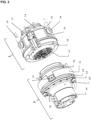
- Fig. 2 and 3 show an example of the structure of the atomizer changing system ( Fig. 2 ) or the construction of the coupling plates ( Fig. 3 : 1.2 , 2.2).
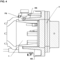
- Fig. 4 illustrates the frictional (KS) and positive (FS) locking of the master unit (1) with the slave unit (2).
- the multi-axis coating robots are those with a “hollow wrist”. All of the lines required to supply the atomizer can be routed through this.
- a typical multi-axis coating robot is, for example, in Fig. 1 shown (from: D. Ondratschek (ed.), yearbook Besser Lack Schl, 65th edition), in which it is designed as a 6-axis coating robot. The six axes are in Fig. 1 marked A1 to A6.
- Multi-axis hollow wrist coating robots preferably have four, five, six or more axes. Particularly preferred in the context of the invention are six-axis hollow wrist coating robots.
- the atomizer changing system allows various types of atomizers to be attached in a simple manner, both manually and preferably fully automatically, without permanently installing all the lines from the hollow wrist to the atomizer switch.
- the master unit (1) of the atomizer changing system according to the invention is firmly connected to the hollow wrist of the coating robot via an adapter (1.3) and the master unit is designed in such a way that it has a master-side coupling plate arranged in the center of the cross section (1.2), which has a plurality of coupling points that serve to supply the atomizer with substances, energy and / or information.
- the cables required for this are firmly connected to the master-side coupling plate (1.2).
- connection or locking mechanism required to connect or lock the master unit (1) to the slave unit (2) in the atomizer changing system according to the invention surrounds the master-side coupling plate (1.2) and is therefore not on the inside but on the outside.
- connection or locking mechanism is designed to be both non-positive (KS) and positive (FS).
- the detachable master-side connecting element (1.1), which surrounds the center of the master unit (1) and enables the non-positive and positive connection (KS, FS) of the master unit (1) to the slave unit (2), is preferred designed as a flange, particularly preferably as a conical flange.
- the construction according to the invention and in particular through a preferred additional nesting of the master-side coupling plate (1.2) with the slave-side coupling plate (2.2) also results in a radial increase Dielectric strength.
- the labyrinth of insulation walls resulting from the interaction of the master-side coupling plate (1.2) and the slave-side coupling plate (2.2) forms extended paths for any leakage currents and is therefore a particularly effective insulation measure that advantageously contributes to improving operational safety.
- the master-side coupling plate (1.2) should be as universally suitable as possible for a wide variety of atomizers, from pneumatic atomizers to high-speed rotary atomizers, it has a plurality of coupling points for supplying the respective atomizer with materials, energy and/or information. This also makes it possible to couple the necessary media, for example directly charged, conductive media.
- the master-side coupling plate (1.2) comprises coupling points for coating agent lines, in particular those that are designed for operation with or without high voltage, coupling points for pneumatic lines, in particular for the supply of turbine ventilation, bearing air, bearing air monitoring, steering ventilation, control ventilation, microphone ventilation, purge air, air for Thermal insulation and brake air, as well as coupling points for fiber optic cables.
- the master coupling plate (1.2) has at least 28 coupling points, of which two media-carrying lines for operation without high voltage, five media-carrying lines for operation under high voltage, twenty pneumatic lines for turbine ventilation, bearing air, bearing air monitoring, steering air, Control air, microphone air, purge air, air for thermal insulation, brake air and a fiber optic cable coupling.
- the bearing air screw connection ( Fig. 3 : 1.22, 2.22), which is permanently pressurized with compressed air during operation, is preferably designed in such a way that it is only opened when the master unit (1) is connected to the slave unit (2). This guarantees that the bearing air that is permanently present in the master unit (1) cannot escape uncontrollably, which means that costs and resources can be saved.
- the atomizer changing system according to the invention can also be used in high-voltage operation with corresponding atomizers up to approximately 100 kV, without the horizontal arm of the robot having to be isolated.
- the atomizer changing system according to the invention allows the use of the atomizer changing system in accordance with the requirements of the EU directives ATEX Product Directive 2014/34/EU and for the ATEX Zone II 3G T3.
- the atomizer changing system according to the invention preferably consists essentially of an electrically non-conductive plastic. Suitable plastics include polyoxymethylene (POM) and polyetheretherketone (PEEK). It is possible to manufacture the slave unit (2) completely from the electrically non-conductive plastic and to manufacture the master unit (1) at least largely from the non-conductive plastic.
- the master unit preferably contains less than 5% by weight, particularly preferably less than 3% by weight and very particularly preferably less than 2% by weight of metallic components. If the master unit (1) contains metallic components, these are usually push-in fittings; High voltage contacts, ground contacts, and catch cylinders (e.g. spring and piston).
- electrically non-conductive plastics such enables the safe adaptation of atomizers weighing up to at least 10 kg but also higher weights such as up to 13 kg, up to 15 kg or higher.
- the center of gravity of the atomizer changing system (including the atomizer) as close as possible to the hollow wrist of the coating robot place.
- the master unit (1) it is preferred to make the master unit (1) as short as possible.
- high-voltage equipment requires that certain insulation distances be maintained. These insulation distances are usually between 1.8 and 2.1 mm/kV and therefore have a strong influence on the component dimensioning.
- all media-carrying lines i.e. the coating agent-carrying lines, have high-voltage-resistant screw connections (1.21, 2.21).
- the master-side high-voltage screw connection (1.21) has a certain strength for possible leakage currents or breakdowns up to a certain voltage.
- the leakage current length is increased and the cavity between the nut/media line/screw connection is preferably filled with an electrically insulating material.
- the screw connection (1.21) described preferably has a dielectric strength or tracking current strength of approximately 50 KV, which means that the insulation distance can be halved.
- the screw connections (1.21, 2.21) for media in general are preferably designed to be free of dead space in order to be able to carry out the cleaning process or the complete evacuation of the lines filled with liquid media in the shortest possible time.
- the slave unit (2) is adapted to the respective atomizer; the interface to the atomizer is formed by the slave-side coupling plate (2.2) and a Slave-side releasable connecting element (2.4), the latter preferably being designed as a flange (2.4).
- the coupling plate (2.2) of the slave unit (2) has lines on the atomizer side and/or an adapter plate for materials, energy and information, preferably produced using a 3D printing process, and is firmly connected to the atomizer.
- the slave coupling plate (2.2) is equipped with all the coupling points necessary for the operation of the respective atomizer.
- the slave unit (2) is preferably designed in such a way that it represents the coupling male of the atomizer changing system. This means that the wear-sensitive sealing elements are located in the slave unit (2). This allows maximum availability of the changing system to be achieved.
- the slave unit (2) preferably has a data carrier (2.7) which can be queried by the master unit (1) at any time.
- the data carrier (2.7) can also serve to recognize the slave unit (2) connected to the atomizer for storage in or removal from a magazine or a changing station.
- a practically implemented embodiment of the atomizer changing system according to the invention is the Figures 2 to 4 removable.
Landscapes
- Engineering & Computer Science (AREA)
- Robotics (AREA)
- Mechanical Engineering (AREA)
- Spray Control Apparatus (AREA)
- Electrostatic Spraying Apparatus (AREA)
- Manipulator (AREA)
- Management, Administration, Business Operations System, And Electronic Commerce (AREA)
- Details Or Accessories Of Spraying Plant Or Apparatus (AREA)
Description
- Die Erfindung betrifft ein Zerstäuberwechselsystem, welches vorzugsweise vollautomatisch Hochrotations- und Pneumatik-Zerstäuber an mehrachsigen Hollow-Wrist-Beschichtungsrobotern wechseln kann.
- Beim Beschichten beziehungsweise Lackieren von hochwertigen Bauteilen, wie es unter anderem in der Automobilindustrie üblich ist, werden hohe Anforderungen an die Beschichtung gestellt. Diese können mit einem einzigen Beschichtungsstoff nicht abgebildet werden, sondern es bedarf hier eines Beschichtungssystems, bestehend aus mehreren Schichten, wobei jede Schicht eine definierte Aufgabe erfüllt. So ist es üblich, dass im Automobilsektor Drei- bis Vierschicht-Aufbauten eingesetzt werden. Solche Mehrschichtbeschichtungssysteme bestehen in der Regel aus einem Primerbeschichtungsmittel, mindestens einem Basislack und mindestens einem (2-Komponenten-)Klarlack. Jedes dieser Beschichtungsmittel wird in der Regel, aufgrund unterschiedlicher Beschaffenheit und unterschiedlicher zu erzielender Applikationsschichtdicke, mit unterschiedlichen Zerstäubern appliziert. Zudem spielt die Zusammensetzung der Beschichtungsmittel eine erhebliche Rolle. So existieren beispielsweise wasserbasierte oder lösemittelbasierte Basislacke, während typische 2-Komponenten-Klarlacke lösemittelhaltig sind. Der Wechsel zwischen wasserbasierten und lösemittelhaltigen Beschichtungsstoffen ist nach erfolgtem Lackiervorgang ohne vorhergehende Reinigung der Applikationsvorrichtung nicht möglich, da der Kontakt zwischen den Beschichtungsstoffen oder ein Vermischen dieser in der Regel zu unerwünschten Reaktionen führt.
- Ein weiteres Applikationsproblem besteht darin, dass Hochrotationszerstäuber den pneumatischen Zerstäubern bezüglich der Erreichbarkeit schwer zugänglicher Flächen unterlegen sind, da diese im konstruktiven Aufbau deutlich größer sind.
- Der manuelle Umbau eines Roboters auf den jeweiligen Zerstäuber ist, aufgrund der Rüstzeit und dem damit verbundenen Stillstand des Lackiervorgangs in der LackierKabine beziehungsweise der gesamten Lackierstraße, zu vermeiden. Aus diesem Grund wird in der Regel für jeden einzelnen Zerstäuber ein separater Roboter benötigt.
- Bekannt sind Werkzeugwechselsysteme für sogenannte Handling-Roboter. Diese bestehen aus einem zentrisch angeordneten Spannelement, um das das am Werkzeug befindliche Kupplungselement (Slave) mit dem am Roboter befindlichen Kupplungselement (Master) greifen und verriegeln zu können. Um dieses Spannelement sind, je nach Anforderung, verschiedene Module angebracht, um die zur Funktion des Werkzeugs benötigten Stoff-, Energie- und Informationsströme zu kuppeln. Diese Kupplungssysteme sind durchgängig aus leitfähigen Materialien und können deshalb nicht im Hochspannungsbereich verbaut werden. Sie sind für den Einsatz an einem Handling-Roboter ohne sogenannten Hollow-Wrist etabliert.
- Auch aus dem Bereich der Lackiertechnik sind bereits vollautomatische Zerstäuberwechselsysteme bekannt (Prauser & Brinckmann in: Journal für Oberflächentechnik 2013(7) 20-21). Diese bestehen aus einer roboterseitigen Masterplatte, über die verschiedene Slaveplatten aufgenommen werden können, an welchen die Zerstäuber mechanisch montiert und verschlaucht sind. Die Slave-Einheiten befinden sich in Wechselstationen innerhalb einer Lackierkabine. So kann ein Roboter vollautomatisch die Zerstäuber wechseln. Das Wechselsystem kann alle für den Betrieb eines Hochrotationszerstäubers notwendigen Medien und Signale kuppeln und ist für den Betrieb von Zerstäubern mit Außen- und Innenaufladung sowie Lackierpistolen geeignet. Auch hier befindet sich das eigentliche Spannelement, ähnlich wie im zuvor beschriebenen Werkzeugwechselsystem, im Zentrum, während die eigentlichen Kuppelstellen für Stoffe, Energie und Informationen außen angeordnet sind. Diese Anordnung nimmt viel Raum in Anspruch, was sich negativ auf die gesamte Kinematik auswirkt. Zudem sind im oben genannten Zerstäuberwechselsystem Komponenten wie Kupplungen, Spannsystem, Halterungen etc. metallisch ausgeführt, was zu unerwünschten Nebeneffekten im Betrieb unter Hochspannung (freie Kapazitäten) führen kann. Des Weiteren ist die gesamte Schlauchführung der Slaveeinheit offen und weitestgehend ungeschützt, wodurch die gesamte Einheit anfällig für Verschmutzung durch Overspray ist.
- Im Anwendungsbereich der KFZ-Lackierung sind sogenannte und bereits vorstehend erwähnte "Hollow Wrist"-Lackierroboter in vielfachem Einsatz. Diese weisen typischerweise vier, fünf oder sechs Achsen auf und besitzen die Besonderheit, dass die Leitungen für Stoffe, Energie und Informationen durch das "hohle Handgelenk" ("Hollow Wrist") des Roboters geführt werden und somit der Verschmutzung durch Overspray unzugänglich sind. Zudem ermöglicht es die "schlanke" Konstruktion auch Stellen des zu lackierenden Gutes zu erreichen, die bei einer Außenführung der Leitungen nicht zugänglich wären. Der Zerstäuberwechsel an derartigen mehrachsigen Hollow-Wrist-Lackierrobotern ist jedoch bisher aufwändig, insbesondere zeitaufwändig und nur manuell durchführbar.
-
US 6,349,884 B1 betrifft ein Verfahren und eine Vorrichtung zur Montage einer Unterbaugruppe, die mindestens eine Sprühvorrichtung zum Sprühen von Beschichtungsmaterial auf einem beweglichen Teil eines Roboters umfasst. - Der Erfindung liegt die Aufgabe zu Grunde ein Zerstäuberwechselsystem bereitzustellen, welches die Nachteile des Standes der Technik nicht aufweist und insbesondere bei Zerstäubern mit größerem Platzbedarf diesen Platz optimal nutzt und somit vor allem bei komplexen dreidimensionalen zu lackierenden Substraten die Erreichbarkeit der zu lackierenden Oberflächen verbessert. Zugleich soll eine äußere Anschmutzung der die Stoffe, Energie und Informationen führenden Leitungen beispielsweise durch Overspray, minimiert. Eine geringere Anschmutzung der Leitungen soll es so ermöglichen, dass die Wechselzeiten zwischen verschiedenen Zerstäubern reduziert werden und auch die Gefahr der Kontamination nachfolgender Lackschichten durch außenliegende angeschmutzte Schläuche und Leitungen verringert wird.
- Darüber hinaus soll das Zerstäuberwechselsystem einen schnellen, vollautomatischen Wechsel zwischen verschiedenen Zerstäubern und somit auch verschiedenen Beschichtungsmittelsystemen ermöglichen. Auch soll die Zahl der für eine Mehrschichtlackierung erforderlichen Lackierrroboter reduziert werden, indem ein Lackierroboter, in raschem Wechsel, mit unterschiedlichen Zerstäubern ausgestattet werden kann. Dies erlaubt die Applikation verschiedener Beschichtungsmittel wie beispielsweise wässriger oder lösemittelbasierter, Ein- oder Zweikomponenten-Beschichtungsmittel.
- Besonders vorteilhaft soll sich das Zerstäuberwechselsystem mit unterschiedlichen Zerstäubern wie beispielsweise Hochrotationszerstäubern und pneumatischen Zerstäubern verwenden lassen. Vorzugsweise sollte jede übliche Art von Zerstäubern einsetzbar sein.
- Das Zerstäuberwechselsystem soll an einem mehrachsigen Lackierroboter verwendbar sein, so dass der Lackierroboter, ohne das Eingreifen des Menschen, in der Lage ist, den Zerstäuber selbstständig zu wechseln.
- Oben genannte Aufgaben konnten durch die Bereitstellung eines Zerstäuberwechselsystems für einen mehrachsigen Hollow-Wrist-Beschichtungsroboter gelöst werden, wobei das Zerstäuberwechselsystem eine Master-Einheit (1) und mindestens eine Slave-Einheit (2) umfasst, und wobei
- die Master-Einheit (1) wenigstens folgende Bauteile aufweist:
- ein das Zentrum der Master-Einheit (1) umgebendes, lösbares masterseitiges Verbindungselement (1.1) zur kraftschlüssigen und
- formschlüssigen Verbindung (KS, FS) der Master-Einheit (1) mit der Slave-Einheit (2),
- eine im Zentrum der Master-Einheit (1) angeordnete masterseitige Kupplungsplatte (1.2) mit einer Mehrzahl von Kupplungsstellen für die Versorgung eines daran anschließbaren Zerstäubers mit Stoffen, Energie und/oder Informationen, und
- einen Adapter (1.3) zum Anschluss der Master-Einheit (1) an einen Hollow-Wrist eines Beschichtungsroboters; und wobei
- die Slave-Einheit (2) wenigstens folgende Bauteile aufweist:
- eine slaveseitige Kupplungsplatte (2.2) zum Anschluss der Slave-Einheit (2) an die Master-Einheit (1) und an einen Zerstäuber, wobei die slaveseitige Kupplungsplatte (2.2) zerstäuberseitig mit Leitungen und/oder einer Adapterplatte für die Versorgung des anschließbaren Zerstäubers mit Stoffen, Energie und/oder Informationen fest verbunden ist; und
- ein slaveseitiges lösbares Verbindungselement (2.4) zur Verbindung der Slave-Einheit (2) mit einem Zerstäuber.
- Im Folgenden wird das Zerstäuberwechselsystem als erfindungsgemäßes Zerstäuberwechselsystem bezeichnet.
-
Fig. 2 und3 zeigen exemplarisch den Aufbau des Zerstäuberwechselsystems (Fig. 2 ) bzw. die Konstruktion der Kupplungsplatten (Fig. 3 :1.2 , 2.2).Fig. 4 veranschaulicht die kraftschlüssige (KS) und formschlüssige (FS) der Master-Einheit (1) mit der Slave-Einheit (2). - Bei den mehrachsigen Beschichtungsrobotern handelt es sich um solche mit einem "Hollow-Wrist", das heißt einem "hohlen Handgelenk". Durch diesen können sämtliche zur Versorgung des Zerstäubers benötigten Leitungen geführt werden. Ein typischer mehrachsiger Beschichtungsroboter ist beispielsweise in
Fig. 1 dargestellt (aus: D. Ondratschek (Hrsg.), Jahrbuch Besser Lackieren 2008, 65. Auflage), worin dieser als 6-achsiger Beschichtungsroboter ausgeführt ist. Die sechs Achsen sind inFig. 1 mit A1 bis A6 gekennzeichnet. - Mehrachsige Hollow-Wrist-Beschichtungsroboter besitzen vorzugsweise vier, fünf, sechs oder mehr Achsen. Besonders bevorzugt handelt es sich im Rahmen der Erfindung um sechsachsige Hollow-Wrist-Beschichtungsroboter.
- Während bei den aus dem Stand der Technik bekannten mehrachsigen Beschichtungsrobotern die zur Versorgung des Zerstäubers benötigten Leitungen für Stoffe, Energie und/oder Informationen außen am Roboterarm entlanggeführt werden und daher sowohl der Raumbedarf als auch die Anschmutzungsneigung erhöht sind, erlaubt es das erfindungsgemäße Zerstäuberwechselsystem, ohne festen Verbau aller Leitungen vom Hollow-Wrist bis zum Zerstäuber, verschiedenste Arten an Zerstäubern auf einfache Art und Weise, sowohl manuell, vorzugsweise jedoch vollautomatisch anzubringen beziehungsweise zu wechseln.
- Dies gelingt dadurch, dass die Master-Einheit (1) des erfindungsgemäßen Zerstäuberwechselsystems über einen Adapter (1.3) fest mit dem Hollow-Wrist des Beschichtungsroboters verbunden wird und die Master-Einheit so ausgestaltet ist, dass diese einen im Zentrum des Querschnitts angeordnete masterseitige Kupplungsplatte (1.2) aufweist, welche eine Mehrzahl von Kupplungsstellen aufweist, die der Versorgung des Zerstäubers mit Stoffen, Energie und/oder Informationen dienen. Roboterseitig werden die hierfür erforderlichen Leitungen fest mit der masterseitigen Kupplungsplatte (1.2) verbunden.
- Anders als bei Master-Slave-Wechselvorrichtungen für typische Handling-Roboter, umgibt der zur Verbindung bzw. Verriegelung der Master-Einheit (1) mit der Slave-Einheit (2) erforderliche Verbindungs- bzw. Verriegelungsmechanismus (KS, FS) im erfindungsgemäßen Zerstäuberwechselsystem die masterseitige Kupplungsplatte (1.2) und ist somit nicht innenliegend, sondern außenliegend.
- Der Verbindungs- bzw. Verriegelungsmechanismus ist sowohl kraftschlüssig (KS) als auch formschlüssig (FS) ausgeführt.
- Das lösbare masterseitige Verbindungselement (1.1), welches das Zentrum der Master-Einheit (1) umgibt und die kraft- und formschlüssige Verbindung (KS, FS) der Master-Einheit (1) mit der Slave-Einheit (2) ermöglicht, ist vorzugsweise als Flansch, besonders bevorzugt als Kegelflansch ausgebildet.
- Aus der erfindungsgemäßen Konstruktion und insbesondere durch eine bevorzugte zusätzliche Verschachtelung der masterseitigen Kupplungsplatte (1.2) mit der slaveseitigen Kupplungsplatte (2.2) folgt auch eine radiale Erhöhung der Durchschlagfestigkeit. Das sich im Zusammenwirken von masterseitigen Kupplungsplatte (1.2) und slaveseitigen Kupplungsplatte (2.2) ergebende Labyrinth aus Isolationswandungen bildet verlängerte Wege für etwaige Kriechströme und ist daher eine besonders wirksame Isolationsmaßnahme, die in vorteilhafter Weise zur Verbesserung der Betriebssicherheit beiträgt.
- Zum anderen sind alle Leitungen für Stoffe, Energie und Informationen im Master (1), was die Flexibilität und Erreichbarkeit der Zerstäuber erhöht, und die Reinigung des Systems vereinfacht.
- Da die masterseitige Kupplungsplatte (1.2) möglichst eine universelle Eignung für die verschiedensten Zerstäuber, von pneumatischen Zerstäubern bis hin zu Hochrotationszerstäubern besitzen soll, weist diese eine Mehrzahl von Kupplungsstellen für die Versorgung des jeweiligen Zerstäubers mit Stoffen, Energie und/oder Informationen auf. Somit ist auch das Kuppeln der notwendigen Medien, beispielsweise direktaufgeladenen, leitfähigen Medien möglich.
- Besonders bevorzugt umfasst die masterseitige Kupplungsplatte (1.2) Kupplungsstellen für Beschichtungsmittelleitungen, insbesondere solche die für einen Betrieb mit oder ohne Hochspannung ausgelegt sind, Kupplungsstellen für pneumatische Leitungen insbesondere zur Versorgung mit Turbinenlüften, Lagerluft, Lagerluftüberwachung, Lenklüfte, Steuerlüfte, Mikrofonlüfte, Purgeluft, Luft zur Wärmeisolierung und Bremsluft, sowie Kupplungsstellen für Lichtwellenleiter.
- In einer ganz besonders bevorzugten Ausführungsform weist die Master-Kupplungsplatte (1.2) mindestens 28 Kuppelstellen auf, davon zwei medienführende Leitungen für den Betrieb ohne Hochspannung, fünf medienführende Leitungen für den Betrieb unter Hochspannung, zwanzig pneumatische Leitungen für Turbinenlüfte, Lagerluft, Lagerluftüberwachung, Lenklüfte, Steuerlüfte, Microfonlüfte, Purgeluft, Luft zur Wärmeisolierung, Bremsluft sowie eine Lichtwellenleiterkupplung.
- Die als Lagerluftverschraubung (
Fig. 3 : 1.22, 2.22) ausgeführte, während des Betriebs dauerhaft mit Druckluft beaufschlagte Kupplungsstelle ist vorzugsweise so ausgeführt, dass diese erst beim Verbinden der Master-Einheit (1) mit der Slave-Einheit (2) geöffnet wird. Das garantiert, dass die permanent an der Master-Einheit (1) anstehende Lagerluft nicht unkontrolliert entweichen kann, wodurch Kosten und Ressourcen eingespart werden können. - Das erfindungsgemäße Zerstäuberwechselsystem kann auch im Hochspannungsbetrieb mit entsprechenden Zerstäubern bis etwa 100 kV eingesetzt werden, ohne dass der Horizontalarm des Roboters isoliert ausgeführt werden muss. Das erfindungsgemäße Zerstäuberwechselsystem erlaubt die Verwendung des Zerstäuberwechselsystems gemäß den Anforderungen der EU-Richtlinien ATEX-Produktrichtlinie 2014/34/EU und für die ATEX Zone II 3G T3.
- Vorzugsweise besteht das erfindungsgemäße Zerstäuberwechselsystem im Wesentlichen aus einem elektrisch nicht leitfähigen Kunststoff. Geeignete Kunststoffe sind beispielsweise Polyoxymethylen (POM) und Polyetheretherketon (PEEK). Hierbei ist es möglich die Slave-Einheit (2) komplett aus dem elektrisch nicht leitfähigen Kunststoff zu fertigen und die Master-Einheit (1) zumindest weitestgehend aus dem nicht leitfähigen Kunststoff zu fertigen. So enthält die Master-Einheit vorzugsweise weniger als 5 Gew.-%, besonders bevorzugt weniger als 3 Gew.-% und ganz besonders bevorzugt weniger als 2 Gew.-% an metallischen Bauteilen. Enthält die Master-Einheit (1) metallische Bauteile, so handelt es sich hierbei in der Regel um Steckverschraubungen; Hochspannungs-Kontakte, Erdungs-Kontakte, und Fangzylinder (z.B. Feder und Kolben). Trotz der gewichtsreduzierten Konstruktion unter Verwendung elektrisch nicht leitfähiger Kunststoffe, ermöglicht eine derartige Ausführung die sichere Adaptierung von Zerstäuber bis zu einem Gewicht von mindestens 10 kg aber durchaus auch höheren Gewichten wie beispielsweise bis zu 13 kg, bis zu 15 kg oder höher.
- Es ist vorteilhaft den Schwerpunkt des Zerstäuberwechselsystems (inklusive des Zerstäubers) möglichst nahe am Hollow-Wrist des Beschichtungsroboters zu platzieren. Um dies zu erreichen, ist es bevorzugt die Master-Einheit (1) so kurz wie möglich auszuführen. Allerdings erfordert eine hochspannungsfeste Ausrüstung, dass bestimmte Isolierstrecken eingehalten werden. Diese Isolierstrecken liegen in der Regel zwischen 1,8 und 2,1 mm/kV und haben somit einen starken Einfluss auf die Bauteildimensionierung. Um die Isolierstrecken möglichst gering zu halten, ist es bevorzugt, dass alle medienführenden Leitungen, das heißt die beschichtungsmittelführenden Leitungen hochspannungsfeste Verschraubungen (1.21, 2.21) besitzen.
- Die masterseitige Hochspannungsverschraubung (1.21) weist, bis zu einer bestimmten Spannung, eine gewisse Festigkeit für mögliche Kriechströme bzw. Durchschläge auf. Dabei wird bei der Kombination Mutter/Medienleitung/Verschraubung im fertig montierten Zustand zum einen die Kriechstromlänge erhöht, zum anderen vorzugsweise der Hohlraum zwischen Mutter/ Medienleitung/Verschraubung mit einem elektrisch isolierenden Stoff befüllt. Für eine Befüllung geeignete elektrisch isolierende Stoffe müssen LABS-Konformität gemäß VDMA 24364:2018-05 aufweisen (LABS = lackbenetzungsstörende Substanzen). Hierzu zählen entsprechend konforme Spezialfette und entsprechend konforme Vaseline.
- Die beschriebene Verschraubung (1.21) besitzt vorzugsweise eine Durchschlags- bzw. Kriechstromfestigkeit von etwa 50 KV, wodurch die Isolierstrecke halbiert werden kann.
- Die Verschraubungen (1.21, 2.21) für Medien im Allgemeinen sind vorzugsweise totraumfrei ausgeführt, um den Reinigungsprozess beziehungsweise das vollständige Evakuieren der mit flüssigen Medien gefüllten Leitungen in kürzester Zeit realisieren zu können.
- Die Slave-Einheit (2) ist an den jeweiligen Zerstäuber angepasst, die Schnittstelle zum Zerstäuber bildet hierbei die slaveseitige Kupplungsplatte (2.2) und ein slaveseitiges lösbares Verbindungselement (2.4), wobei letzteres vorzugsweise als Flansch (2.4) ausgebildet ist.
- Die Kupplungsplatte (2.2) der Slave-Einheit (2) weist zerstäuberseitig Leitungen und/oder eine vorzugsweise im 3D-Druckverfahren hergestellte Adapterplatte für Stoffe, Energie und Information auf und ist fest mit dem Zerstäuber verbunden. Die Slave-Kupplungsplatte (2.2) ist dabei mit allen für den Betrieb des jeweiligen Zerstäubers notwendigen Kupplungsstellen besetzt.
- Die Slave-Einheit (2) ist vorzugsweise so ausgeführt, dass diese das Kupplungsmännchen des Zerstäuberwechselsystems darstellt. Das heißt, dass sich die verschleißempfindlichen Dichtelemente in der Slave-Einheit (2) befinden. Hierdurch kann eine maximale Verfügbarkeit des Wechselsystems erreicht werden.
- Vorzugsweise verfügt die Slave-Einheit (2) über einen Datenträger (2.7), der von der Master-Einheit (1) jeder Zeit abgefragt werden kann. Hierzu dient eine vorzugsweise an der Master-Einheit (1) befindliche Leseeinheit (1.7).
- Der Datenträger (2.7) kann auch dazu dienen, dass die mit dem Zerstäuber verbundene Slave-Einheit (2) zur Ablage in oder Entnahme aus einem Magazin bzw. einer Wechselstation erkannt wird.
- Neben dem vollautomatischen Wechsel der Zerstäuber sowie der Ablage in oder Entnahme aus einem Magazin bzw. einer Wechselstation, ist es jedoch auch möglich den mit der Slave-Einheit (2) verbundenen Zerstäuber von Hand am Roboter zu wechseln, ohne dass ein Magazin beziehungsweise eine Wechselstation angefahren werden muss.
- Eine praktisch realisierte Ausführung des erfindungsgemäßen Zerstäuberwechselsystems ist den
Figuren 2 bis 4 entnehmbar. -
- 1:
- Master-Einheit
- 1.1:
- Masterseitiges lösbares Verbindungselement (Kegelflansch) zur kraft- und formschlüssigen Verbindung der Master-Einheit (1) mit der Slave-Einheit (2)
- 1.2:
- Masterseitige Kupplungsstellen an der Master-Einheit (1)
- 1.21:
- (hochspannungsfeste) Verschraubung an der Master-Einheit (1)
- 1.22:
- Lagerluftverschraubung an der Master-Einheit (1)
- 1.3:
- Adapter zum Anschluss der Master-Einheit (1) an den Hollow-Wrist eines Beschichtungsroboters
- 1.4:
- formschlüssig ausgeführter Fangzylinder
- 1.5:
- masterseitige Kupplung für Hochspannung bzw. Erde
- 1.6:
- Zentrierbuchse bzw. -bohrung (um die Slave-Einheit beim Kuppeln zu zentrieren)
- 1.7:
- Leseeinheit für den Datenträger 2.7
- 2:
- Slave-Einheit
- 2.1:
- Slaveseitiges lösbares Verbindungselement (Kegelflansch) zur kraft- und formschlüssigen Verbindung der Master-Einheit (1) mit der Slave-Einheit (2)
- 2.2:
- Slaveseitige Kupplungsplatte an der Slave-Einheit (1)
- 2.21:
- (hochspannungsfeste) Verschraubung an der Slave-Einheit (2)
- 2.22:
- Lagerluftverschraubung an der Slave-Einheit (2)
- 2.3:
- Fangflansch (Zentrierung bzw. Möglichkeit des Fixierens der Slave-Einheit in der Wechselstation)
- 2.4:
- Slaveseitiges lösbares Verbindungselement (Adapterflansch) zur Verbindung der Slave-Einheit (2) mit einem Zerstäuber
- 2.5:
- slaveseitige Kupplung für Hochspannung bzw. Erde
- 2.6:
- Zentrierdorne (um die Slave-Einheit beim Kuppeln zu zentrieren)
- 2.7:
- Datenträger
- KS:
- kraftschlüssige Verbindung
- FS:
- formschlüssige Verbindung
Claims (10)
- Zerstäuberwechselsystem, umfassend eine Master-Einheit (1) und mindestens eine Slave-Einheit (2), wobeidie Master-Einheit (1) wenigstens folgende Bauteile aufweist:
ein das Zentrum der Master-Einheit (1) umgebendes, masterseitiges Verbindungselement (1.1) zur kraftschlüssigen und formschlüssigen Verbindung (KS, FS) der Master-Einheit (1) mit der Slave-Einheit (2), und eine im Zentrum der Master-Einheit (1) angeordnete masterseitige Kupplungsplatte (1.2) mit einer Mehrzahl von Kupplungsstellen für die Versorgung eines daran anschließbaren Zerstäubers mit Stoffen, Energie und/oder Informationen; und wobeidie Slave-Einheit (2) wenigstens folgendes Bauteil aufweist:
ein slaveseitiges lösbares Verbindungselement (2.4) zur Verbindung der Slave-Einheit (2) mit einem Zerstäuber,dadurch gekennzeichnet, dass das masterseitige Verbindungselement (1.1) lösbar ist, die Master-Einheit (1) einen Adapter (1.3) zum Anschluss der Master-Einheit (1) an einen Hollow-Wrist eines Beschichtungsroboters aufweist und die Slave-Einheit (2) eine slaveseitige Kupplungsplatte (2.2) zum Anschluss der Slave-Einheit (2) an die Master-Einheit (1) und an einen Zerstäuber aufweist, wobei die slaveseitige Kupplungsplatte (2.2) zerstäuberseitig mit Leitungen und/oder einer Adapterplatte für die Versorgung des anschließbaren Zerstäubers mit Stoffen, Energie und/oder Informationen fest verbunden ist. - Zerstäuberwechselsystem gemäß Anspruch 1, wobei die masterseitige Kupplungsplatte (1.2) eine Mehrzahl an Kupplungsstellen gewählt aus Kupplungsstellen für Beschichtungsmittelleitungen, Kupplungsstellen für pneumatische Leitungen und Kupplungsstellen für Lichtwellenleiter besitzt.
- Zerstäuberwechselsystem gemäß Anspruch 2, wobei die Kupplungsstellen für Beschichtungsmittelleitungen, für einen Betrieb mit oder ohne Hochspannung ausgelegt sind und die Kupplungsstellen für pneumatische Leitungen zur Versorgung mit Turbinenlüften, Lagerluft, Lagerluftüberwachung, Lenklüften, Steuerlüften, Mikrofonlüften, Purgeluft, Luft zur Wärmeisolierung und Bremsluft dienen.
- Zerstäuberwechselsystem gemäß Anspruch 3, wobei die Kupplungsstelle für die Lagerluft (1.22, 2.22) so ausgeführt ist, dass diese erst beim Verbinden der Master-Einheit (1) mit der Slave-Einheit (2) geöffnet wird.
- Zerstäuberwechselsystem gemäß einem oder mehreren der Ansprüche 1 bis 4, wobei dieses im Wesentlichen aus einem elektrisch nicht leitfähigen Kunststoff besteht.
- Zerstäuberwechselsystem gemäß Anspruch 5, wobei die Slave-Einheit (2) aus einem elektrisch nicht leitfähigen Kunststoff besteht und die Master-Einheit (1) zu mindestens 95 Gew.-%, bezogen auf das Gewicht der Master-Einheit (1), aus einem elektrisch nicht leitfähigen Kunststoff besteht.
- Zerstäuberwechselsystem gemäß einem oder mehreren der Ansprüche 1 bis 6, wobei die Versorgung des Zerstäubers mit Beschichtungsmitteln über beschichtungsmittelführenden Leitungen erfolgt, die mit den Kupplungsplatten (1.2, 2.2) über hochspannungsfeste Verschraubungen (1.21, 2.21) verbunden sind.
- Zerstäuberwechselsystem gemäß Anspruch 7, wobei die hochspannungsfesten Verschraubungen (1.21, 2.21) totraumfrei ausgeführt sind.
- Zerstäuberwechselsystem gemäß einem oder mehreren der Ansprüche 1 bis 8, wobei die Slave-Einheit (2) einen Datenträger (2.7) umfasst, der von einer an der Master-Einheit (1) angebrachten Leseeinheit (1.7) auslesbar ist.
- Zerstäuberwechselsystem gemäß einem oder mehreren der Ansprüche 1 bis 9, wobei die masterseitige Kupplungsplatte (1.2) und die slaveseitige Kupplungsplatte (2.2) so ausgeführt sind, dass sich beim Zusammenfügen beider Kupplungsplatten (1.2, 2.2) ein Labyrinth für etwaige Kriechströme ergibt.
Applications Claiming Priority (2)
| Application Number | Priority Date | Filing Date | Title |
|---|---|---|---|
| EP20165481 | 2020-03-25 | ||
| PCT/EP2021/057812 WO2021191383A1 (de) | 2020-03-25 | 2021-03-25 | Zerstäuberwechselsystem für mehrachsige hollow-wrist-beschichtungsroboter |
Publications (2)
| Publication Number | Publication Date |
|---|---|
| EP4126387A1 EP4126387A1 (de) | 2023-02-08 |
| EP4126387B1 true EP4126387B1 (de) | 2024-03-06 |
Family
ID=69960553
Family Applications (1)
| Application Number | Title | Priority Date | Filing Date |
|---|---|---|---|
| EP21713975.7A Active EP4126387B1 (de) | 2020-03-25 | 2021-03-25 | Zerstäuberwechselsystem für mehrachsige hollow-wrist-beschichtungsroboter |
Country Status (9)
| Country | Link |
|---|---|
| US (1) | US12325036B2 (de) |
| EP (1) | EP4126387B1 (de) |
| JP (1) | JP2023518493A (de) |
| KR (1) | KR20220151704A (de) |
| CN (1) | CN115335155A (de) |
| CA (1) | CA3172173A1 (de) |
| ES (1) | ES2981258T3 (de) |
| MX (1) | MX2022011763A (de) |
| WO (1) | WO2021191383A1 (de) |
Families Citing this family (3)
| Publication number | Priority date | Publication date | Assignee | Title |
|---|---|---|---|---|
| DE102021101027A1 (de) * | 2021-01-19 | 2022-07-21 | Dürr Systems Ag | Beschichtungseinrichtung, insbesondere Lackierroboter |
| DE102021101028B4 (de) * | 2021-01-19 | 2024-02-22 | Dürr Systems Ag | Beschichtungseinrichtung mit einem Rotationszerstäuber |
| CN118559728B (zh) * | 2024-07-31 | 2024-09-27 | 深圳市荣德机器人科技有限公司 | 一种可伸缩式汽车喷涂机器人 |
Family Cites Families (10)
| Publication number | Priority date | Publication date | Assignee | Title |
|---|---|---|---|---|
| DE29905689U1 (de) * | 1999-03-27 | 1999-07-29 | ITW Oberflächentechnik GmbH, 63128 Dietzenbach | Sprühpistolen-Roboter-Adapter |
| FR2797789B1 (fr) * | 1999-08-30 | 2001-11-23 | Sames Sa | Procede et dispositif de montage d'un sous-ensemble comprenant au moins un projecteur de produit de revetement sur une partie mobile d'un robot |
| DE10103067A1 (de) * | 2001-01-24 | 2002-07-25 | Duerr Systems Gmbh | Beschichtungsmaschine mit einem auswechselbaren Applikationsorgan |
| US20060102075A1 (en) * | 2004-11-18 | 2006-05-18 | Saylor Austin A | Fluid flow control |
| JP4705818B2 (ja) * | 2005-07-29 | 2011-06-22 | トヨタ自動車株式会社 | 静電塗装装置 |
| US7908994B2 (en) * | 2005-10-21 | 2011-03-22 | Duerr Systems, Inc. | Automatically steered coating machine also a container for the coating material |
| DE102006022570A1 (de) * | 2006-05-15 | 2007-11-29 | Dürr Systems GmbH | Beschichtungseinrichtung und zugehöriges Betriebsverfahren |
| DE102007014216A1 (de) * | 2007-03-24 | 2008-09-25 | ITW Oberflächentechnik GmbH & Co. KG | Spritzpistolen-Leistungsverbindungsvorrichtung |
| DE102009013979A1 (de) | 2009-03-19 | 2010-09-23 | Dürr Systems GmbH | Elektrodenanordnung für einen elektrostatischen Zerstäuber |
| DE102012022535A1 (de) * | 2012-11-16 | 2014-05-22 | Eisenmann Ag | Applikator-Anschlusseinheit, Applikationsroboter und Anlage zum Beschichten von Gegenständen |
-
2021
- 2021-03-25 ES ES21713975T patent/ES2981258T3/es active Active
- 2021-03-25 MX MX2022011763A patent/MX2022011763A/es unknown
- 2021-03-25 JP JP2022557163A patent/JP2023518493A/ja active Pending
- 2021-03-25 CN CN202180024106.3A patent/CN115335155A/zh active Pending
- 2021-03-25 CA CA3172173A patent/CA3172173A1/en active Pending
- 2021-03-25 US US17/907,033 patent/US12325036B2/en active Active
- 2021-03-25 WO PCT/EP2021/057812 patent/WO2021191383A1/de not_active Ceased
- 2021-03-25 EP EP21713975.7A patent/EP4126387B1/de active Active
- 2021-03-25 KR KR1020227036589A patent/KR20220151704A/ko not_active Withdrawn
Also Published As
| Publication number | Publication date |
|---|---|
| US12325036B2 (en) | 2025-06-10 |
| CA3172173A1 (en) | 2021-09-30 |
| EP4126387A1 (de) | 2023-02-08 |
| JP2023518493A (ja) | 2023-05-01 |
| US20230124016A1 (en) | 2023-04-20 |
| CN115335155A (zh) | 2022-11-11 |
| MX2022011763A (es) | 2023-01-16 |
| WO2021191383A1 (de) | 2021-09-30 |
| KR20220151704A (ko) | 2022-11-15 |
| ES2981258T3 (es) | 2024-10-08 |
Similar Documents
| Publication | Publication Date | Title |
|---|---|---|
| DE112019002283T5 (de) | Robotergesteuerte vorrichtung für eine kompakte lackierkabine | |
| WO2021191383A1 (de) | Zerstäuberwechselsystem für mehrachsige hollow-wrist-beschichtungsroboter | |
| EP2268415B1 (de) | Lackierroboter und zugehöriges betriebsverfahren | |
| DE60311519T2 (de) | Modulare beschichtungsvorrichtung | |
| EP2919917B1 (de) | Applikationsroboter mit anschlusseinheit für verschiedene applikatoren | |
| EP2976158B1 (de) | Spritzvorrichtung, schnellwechseladapter | |
| DE10115467A1 (de) | Werkzeugwechselsystem für eine Maschine | |
| WO2010025827A1 (de) | Lackiereinrichtung und zugehöriges verfahren | |
| EP2185292A1 (de) | Verfahren zur errichtung einer lackieranlage an einem vorgegebenen aufstellungsort | |
| EP2089164A2 (de) | Universalzerstäuber und zugehöriges betriebsverfahren | |
| EP2791008B1 (de) | Beschichtungsanlage und entsprechendes betriebsverfahren | |
| DE10115470A1 (de) | Beschichtungsanlage mit einer Zerstäuberwechselstation | |
| EP0684080A1 (de) | Elektrostatische Sprühvorrichtung | |
| EP1859872B1 (de) | Wechseleinheit für Beschichtungsmaterial | |
| EP3930967B1 (de) | Schraubwerkzeug zur handhabung von verschlusselementen an fahrzeugbehältern zur aufnahme von betriebsstoffen | |
| DE102004040162B4 (de) | Vorrichtung zum Beschichten von Gegenständen | |
| DE10103067A1 (de) | Beschichtungsmaschine mit einem auswechselbaren Applikationsorgan | |
| DE102010000470A1 (de) | Prüfvorrichtung und Prüfverfahren zum Prüfen der Funktionsfähigkeit einer Zerstäubereinrichtung zum Aufbringen eines Beschichtungsmittels | |
| DE102016121637A1 (de) | Applikator für einen Applikationsroboter und Applikationssystem | |
| EP3119566B1 (de) | Roboteranordnung und entsprechendes montageverfahren | |
| DE19940542A1 (de) | Verfahren und Anordnung zum Transport von elektrisch leitfähigem Lack | |
| DE102004034021B4 (de) | Verstelleinheit für eine Pistole einer Lackiereinrichtung und Lackieranlage | |
| DE10205593A1 (de) | Beschichtungsmaschine mit einem Zerstäuber und einem Zerstäuber und einem Drehgelenk | |
| DE202019005366U1 (de) | Automatisches Lackiersystem | |
| WO2025108756A1 (de) | Fixierhilfe für bauteile in einem sprüh- oder spritzsystem und sprüh- oder spritzapplikator zum beschichten von werkstücken mit fixierhilfe |
Legal Events
| Date | Code | Title | Description |
|---|---|---|---|
| STAA | Information on the status of an ep patent application or granted ep patent |
Free format text: STATUS: UNKNOWN |
|
| STAA | Information on the status of an ep patent application or granted ep patent |
Free format text: STATUS: THE INTERNATIONAL PUBLICATION HAS BEEN MADE |
|
| PUAI | Public reference made under article 153(3) epc to a published international application that has entered the european phase |
Free format text: ORIGINAL CODE: 0009012 |
|
| STAA | Information on the status of an ep patent application or granted ep patent |
Free format text: STATUS: REQUEST FOR EXAMINATION WAS MADE |
|
| 17P | Request for examination filed |
Effective date: 20221025 |
|
| AK | Designated contracting states |
Kind code of ref document: A1 Designated state(s): AL AT BE BG CH CY CZ DE DK EE ES FI FR GB GR HR HU IE IS IT LI LT LU LV MC MK MT NL NO PL PT RO RS SE SI SK SM TR |
|
| DAV | Request for validation of the european patent (deleted) | ||
| DAX | Request for extension of the european patent (deleted) | ||
| GRAP | Despatch of communication of intention to grant a patent |
Free format text: ORIGINAL CODE: EPIDOSNIGR1 |
|
| STAA | Information on the status of an ep patent application or granted ep patent |
Free format text: STATUS: GRANT OF PATENT IS INTENDED |
|
| INTG | Intention to grant announced |
Effective date: 20231023 |
|
| GRAS | Grant fee paid |
Free format text: ORIGINAL CODE: EPIDOSNIGR3 |
|
| GRAA | (expected) grant |
Free format text: ORIGINAL CODE: 0009210 |
|
| STAA | Information on the status of an ep patent application or granted ep patent |
Free format text: STATUS: THE PATENT HAS BEEN GRANTED |
|
| AK | Designated contracting states |
Kind code of ref document: B1 Designated state(s): AL AT BE BG CH CY CZ DE DK EE ES FI FR GB GR HR HU IE IS IT LI LT LU LV MC MK MT NL NO PL PT RO RS SE SI SK SM TR |
|
| REG | Reference to a national code |
Ref country code: CH Ref legal event code: EP |
|
| REG | Reference to a national code |
Ref country code: DE Ref legal event code: R096 Ref document number: 502021002916 Country of ref document: DE |
|
| REG | Reference to a national code |
Ref country code: IE Ref legal event code: FG4D Free format text: LANGUAGE OF EP DOCUMENT: GERMAN |
|
| REG | Reference to a national code |
Ref country code: LT Ref legal event code: MG9D |
|
| PG25 | Lapsed in a contracting state [announced via postgrant information from national office to epo] |
Ref country code: LT Free format text: LAPSE BECAUSE OF FAILURE TO SUBMIT A TRANSLATION OF THE DESCRIPTION OR TO PAY THE FEE WITHIN THE PRESCRIBED TIME-LIMIT Effective date: 20240306 |
|
| REG | Reference to a national code |
Ref country code: NL Ref legal event code: MP Effective date: 20240306 |
|
| PG25 | Lapsed in a contracting state [announced via postgrant information from national office to epo] |
Ref country code: GR Free format text: LAPSE BECAUSE OF FAILURE TO SUBMIT A TRANSLATION OF THE DESCRIPTION OR TO PAY THE FEE WITHIN THE PRESCRIBED TIME-LIMIT Effective date: 20240607 |
|
| PG25 | Lapsed in a contracting state [announced via postgrant information from national office to epo] |
Ref country code: RS Free format text: LAPSE BECAUSE OF FAILURE TO SUBMIT A TRANSLATION OF THE DESCRIPTION OR TO PAY THE FEE WITHIN THE PRESCRIBED TIME-LIMIT Effective date: 20240606 Ref country code: HR Free format text: LAPSE BECAUSE OF FAILURE TO SUBMIT A TRANSLATION OF THE DESCRIPTION OR TO PAY THE FEE WITHIN THE PRESCRIBED TIME-LIMIT Effective date: 20240306 |
|
| PG25 | Lapsed in a contracting state [announced via postgrant information from national office to epo] |
Ref country code: RS Free format text: LAPSE BECAUSE OF FAILURE TO SUBMIT A TRANSLATION OF THE DESCRIPTION OR TO PAY THE FEE WITHIN THE PRESCRIBED TIME-LIMIT Effective date: 20240606 Ref country code: NO Free format text: LAPSE BECAUSE OF FAILURE TO SUBMIT A TRANSLATION OF THE DESCRIPTION OR TO PAY THE FEE WITHIN THE PRESCRIBED TIME-LIMIT Effective date: 20240606 Ref country code: LT Free format text: LAPSE BECAUSE OF FAILURE TO SUBMIT A TRANSLATION OF THE DESCRIPTION OR TO PAY THE FEE WITHIN THE PRESCRIBED TIME-LIMIT Effective date: 20240306 Ref country code: HR Free format text: LAPSE BECAUSE OF FAILURE TO SUBMIT A TRANSLATION OF THE DESCRIPTION OR TO PAY THE FEE WITHIN THE PRESCRIBED TIME-LIMIT Effective date: 20240306 Ref country code: GR Free format text: LAPSE BECAUSE OF FAILURE TO SUBMIT A TRANSLATION OF THE DESCRIPTION OR TO PAY THE FEE WITHIN THE PRESCRIBED TIME-LIMIT Effective date: 20240607 Ref country code: FI Free format text: LAPSE BECAUSE OF FAILURE TO SUBMIT A TRANSLATION OF THE DESCRIPTION OR TO PAY THE FEE WITHIN THE PRESCRIBED TIME-LIMIT Effective date: 20240306 Ref country code: BG Free format text: LAPSE BECAUSE OF FAILURE TO SUBMIT A TRANSLATION OF THE DESCRIPTION OR TO PAY THE FEE WITHIN THE PRESCRIBED TIME-LIMIT Effective date: 20240306 |
|
| PG25 | Lapsed in a contracting state [announced via postgrant information from national office to epo] |
Ref country code: SE Free format text: LAPSE BECAUSE OF FAILURE TO SUBMIT A TRANSLATION OF THE DESCRIPTION OR TO PAY THE FEE WITHIN THE PRESCRIBED TIME-LIMIT Effective date: 20240306 Ref country code: LV Free format text: LAPSE BECAUSE OF FAILURE TO SUBMIT A TRANSLATION OF THE DESCRIPTION OR TO PAY THE FEE WITHIN THE PRESCRIBED TIME-LIMIT Effective date: 20240306 |
|
| PG25 | Lapsed in a contracting state [announced via postgrant information from national office to epo] |
Ref country code: NL Free format text: LAPSE BECAUSE OF FAILURE TO SUBMIT A TRANSLATION OF THE DESCRIPTION OR TO PAY THE FEE WITHIN THE PRESCRIBED TIME-LIMIT Effective date: 20240306 |
|
| PG25 | Lapsed in a contracting state [announced via postgrant information from national office to epo] |
Ref country code: NL Free format text: LAPSE BECAUSE OF FAILURE TO SUBMIT A TRANSLATION OF THE DESCRIPTION OR TO PAY THE FEE WITHIN THE PRESCRIBED TIME-LIMIT Effective date: 20240306 |
|
| PG25 | Lapsed in a contracting state [announced via postgrant information from national office to epo] |
Ref country code: IS Free format text: LAPSE BECAUSE OF FAILURE TO SUBMIT A TRANSLATION OF THE DESCRIPTION OR TO PAY THE FEE WITHIN THE PRESCRIBED TIME-LIMIT Effective date: 20240706 |
|
| REG | Reference to a national code |
Ref country code: ES Ref legal event code: FG2A Ref document number: 2981258 Country of ref document: ES Kind code of ref document: T3 Effective date: 20241008 |
|
| PG25 | Lapsed in a contracting state [announced via postgrant information from national office to epo] |
Ref country code: PT Free format text: LAPSE BECAUSE OF FAILURE TO SUBMIT A TRANSLATION OF THE DESCRIPTION OR TO PAY THE FEE WITHIN THE PRESCRIBED TIME-LIMIT Effective date: 20240708 Ref country code: SM Free format text: LAPSE BECAUSE OF FAILURE TO SUBMIT A TRANSLATION OF THE DESCRIPTION OR TO PAY THE FEE WITHIN THE PRESCRIBED TIME-LIMIT Effective date: 20240306 |
|
| PG25 | Lapsed in a contracting state [announced via postgrant information from national office to epo] |
Ref country code: CZ Free format text: LAPSE BECAUSE OF FAILURE TO SUBMIT A TRANSLATION OF THE DESCRIPTION OR TO PAY THE FEE WITHIN THE PRESCRIBED TIME-LIMIT Effective date: 20240306 Ref country code: EE Free format text: LAPSE BECAUSE OF FAILURE TO SUBMIT A TRANSLATION OF THE DESCRIPTION OR TO PAY THE FEE WITHIN THE PRESCRIBED TIME-LIMIT Effective date: 20240306 |
|
| PG25 | Lapsed in a contracting state [announced via postgrant information from national office to epo] |
Ref country code: PL Free format text: LAPSE BECAUSE OF FAILURE TO SUBMIT A TRANSLATION OF THE DESCRIPTION OR TO PAY THE FEE WITHIN THE PRESCRIBED TIME-LIMIT Effective date: 20240306 |
|
| PG25 | Lapsed in a contracting state [announced via postgrant information from national office to epo] |
Ref country code: SK Free format text: LAPSE BECAUSE OF FAILURE TO SUBMIT A TRANSLATION OF THE DESCRIPTION OR TO PAY THE FEE WITHIN THE PRESCRIBED TIME-LIMIT Effective date: 20240306 |
|
| PG25 | Lapsed in a contracting state [announced via postgrant information from national office to epo] |
Ref country code: SM Free format text: LAPSE BECAUSE OF FAILURE TO SUBMIT A TRANSLATION OF THE DESCRIPTION OR TO PAY THE FEE WITHIN THE PRESCRIBED TIME-LIMIT Effective date: 20240306 Ref country code: SK Free format text: LAPSE BECAUSE OF FAILURE TO SUBMIT A TRANSLATION OF THE DESCRIPTION OR TO PAY THE FEE WITHIN THE PRESCRIBED TIME-LIMIT Effective date: 20240306 Ref country code: RO Free format text: LAPSE BECAUSE OF FAILURE TO SUBMIT A TRANSLATION OF THE DESCRIPTION OR TO PAY THE FEE WITHIN THE PRESCRIBED TIME-LIMIT Effective date: 20240306 Ref country code: PT Free format text: LAPSE BECAUSE OF FAILURE TO SUBMIT A TRANSLATION OF THE DESCRIPTION OR TO PAY THE FEE WITHIN THE PRESCRIBED TIME-LIMIT Effective date: 20240708 Ref country code: PL Free format text: LAPSE BECAUSE OF FAILURE TO SUBMIT A TRANSLATION OF THE DESCRIPTION OR TO PAY THE FEE WITHIN THE PRESCRIBED TIME-LIMIT Effective date: 20240306 Ref country code: IS Free format text: LAPSE BECAUSE OF FAILURE TO SUBMIT A TRANSLATION OF THE DESCRIPTION OR TO PAY THE FEE WITHIN THE PRESCRIBED TIME-LIMIT Effective date: 20240706 Ref country code: EE Free format text: LAPSE BECAUSE OF FAILURE TO SUBMIT A TRANSLATION OF THE DESCRIPTION OR TO PAY THE FEE WITHIN THE PRESCRIBED TIME-LIMIT Effective date: 20240306 Ref country code: CZ Free format text: LAPSE BECAUSE OF FAILURE TO SUBMIT A TRANSLATION OF THE DESCRIPTION OR TO PAY THE FEE WITHIN THE PRESCRIBED TIME-LIMIT Effective date: 20240306 |
|
| REG | Reference to a national code |
Ref country code: CH Ref legal event code: PL |
|
| PG25 | Lapsed in a contracting state [announced via postgrant information from national office to epo] |
Ref country code: LU Free format text: LAPSE BECAUSE OF NON-PAYMENT OF DUE FEES Effective date: 20240325 |
|
| PG25 | Lapsed in a contracting state [announced via postgrant information from national office to epo] |
Ref country code: LU Free format text: LAPSE BECAUSE OF NON-PAYMENT OF DUE FEES Effective date: 20240325 |
|
| PG25 | Lapsed in a contracting state [announced via postgrant information from national office to epo] |
Ref country code: IT Free format text: LAPSE BECAUSE OF FAILURE TO SUBMIT A TRANSLATION OF THE DESCRIPTION OR TO PAY THE FEE WITHIN THE PRESCRIBED TIME-LIMIT Effective date: 20240306 |
|
| REG | Reference to a national code |
Ref country code: DE Ref legal event code: R097 Ref document number: 502021002916 Country of ref document: DE |
|
| REG | Reference to a national code |
Ref country code: BE Ref legal event code: MM Effective date: 20240331 |
|
| PG25 | Lapsed in a contracting state [announced via postgrant information from national office to epo] |
Ref country code: IT Free format text: LAPSE BECAUSE OF FAILURE TO SUBMIT A TRANSLATION OF THE DESCRIPTION OR TO PAY THE FEE WITHIN THE PRESCRIBED TIME-LIMIT Effective date: 20240306 |
|
| PG25 | Lapsed in a contracting state [announced via postgrant information from national office to epo] |
Ref country code: MC Free format text: LAPSE BECAUSE OF FAILURE TO SUBMIT A TRANSLATION OF THE DESCRIPTION OR TO PAY THE FEE WITHIN THE PRESCRIBED TIME-LIMIT Effective date: 20240306 |
|
| PLBE | No opposition filed within time limit |
Free format text: ORIGINAL CODE: 0009261 |
|
| STAA | Information on the status of an ep patent application or granted ep patent |
Free format text: STATUS: NO OPPOSITION FILED WITHIN TIME LIMIT |
|
| PG25 | Lapsed in a contracting state [announced via postgrant information from national office to epo] |
Ref country code: DK Free format text: LAPSE BECAUSE OF FAILURE TO SUBMIT A TRANSLATION OF THE DESCRIPTION OR TO PAY THE FEE WITHIN THE PRESCRIBED TIME-LIMIT Effective date: 20240306 |
|
| PG25 | Lapsed in a contracting state [announced via postgrant information from national office to epo] |
Ref country code: BE Free format text: LAPSE BECAUSE OF NON-PAYMENT OF DUE FEES Effective date: 20240331 |
|
| PG25 | Lapsed in a contracting state [announced via postgrant information from national office to epo] |
Ref country code: IE Free format text: LAPSE BECAUSE OF NON-PAYMENT OF DUE FEES Effective date: 20240325 |
|
| PG25 | Lapsed in a contracting state [announced via postgrant information from national office to epo] |
Ref country code: MC Free format text: LAPSE BECAUSE OF FAILURE TO SUBMIT A TRANSLATION OF THE DESCRIPTION OR TO PAY THE FEE WITHIN THE PRESCRIBED TIME-LIMIT Effective date: 20240306 Ref country code: IE Free format text: LAPSE BECAUSE OF NON-PAYMENT OF DUE FEES Effective date: 20240325 Ref country code: DK Free format text: LAPSE BECAUSE OF FAILURE TO SUBMIT A TRANSLATION OF THE DESCRIPTION OR TO PAY THE FEE WITHIN THE PRESCRIBED TIME-LIMIT Effective date: 20240306 Ref country code: BE Free format text: LAPSE BECAUSE OF NON-PAYMENT OF DUE FEES Effective date: 20240331 Ref country code: CH Free format text: LAPSE BECAUSE OF NON-PAYMENT OF DUE FEES Effective date: 20240331 |
|
| 26N | No opposition filed |
Effective date: 20241209 |
|
| PG25 | Lapsed in a contracting state [announced via postgrant information from national office to epo] |
Ref country code: SI Free format text: LAPSE BECAUSE OF FAILURE TO SUBMIT A TRANSLATION OF THE DESCRIPTION OR TO PAY THE FEE WITHIN THE PRESCRIBED TIME-LIMIT Effective date: 20240306 |
|
| PGFP | Annual fee paid to national office [announced via postgrant information from national office to epo] |
Ref country code: AT Payment date: 20250417 Year of fee payment: 5 |
|
| PGFP | Annual fee paid to national office [announced via postgrant information from national office to epo] |
Ref country code: ES Payment date: 20250417 Year of fee payment: 5 |
|
| PG25 | Lapsed in a contracting state [announced via postgrant information from national office to epo] |
Ref country code: CY Free format text: LAPSE BECAUSE OF FAILURE TO SUBMIT A TRANSLATION OF THE DESCRIPTION OR TO PAY THE FEE WITHIN THE PRESCRIBED TIME-LIMIT; INVALID AB INITIO Effective date: 20210325 |
|
| PG25 | Lapsed in a contracting state [announced via postgrant information from national office to epo] |
Ref country code: HU Free format text: LAPSE BECAUSE OF FAILURE TO SUBMIT A TRANSLATION OF THE DESCRIPTION OR TO PAY THE FEE WITHIN THE PRESCRIBED TIME-LIMIT; INVALID AB INITIO Effective date: 20210325 |
|
| PG25 | Lapsed in a contracting state [announced via postgrant information from national office to epo] |
Ref country code: TR Free format text: LAPSE BECAUSE OF FAILURE TO SUBMIT A TRANSLATION OF THE DESCRIPTION OR TO PAY THE FEE WITHIN THE PRESCRIBED TIME-LIMIT Effective date: 20240306 |
|
| PGFP | Annual fee paid to national office [announced via postgrant information from national office to epo] |
Ref country code: GB Payment date: 20260319 Year of fee payment: 6 |
|
| PGFP | Annual fee paid to national office [announced via postgrant information from national office to epo] |
Ref country code: DE Payment date: 20260320 Year of fee payment: 6 |
|
| PGFP | Annual fee paid to national office [announced via postgrant information from national office to epo] |
Ref country code: FR Payment date: 20260323 Year of fee payment: 6 |