EP4125156A1 - Connector - Google Patents
Connector Download PDFInfo
- Publication number
- EP4125156A1 EP4125156A1 EP22187503.2A EP22187503A EP4125156A1 EP 4125156 A1 EP4125156 A1 EP 4125156A1 EP 22187503 A EP22187503 A EP 22187503A EP 4125156 A1 EP4125156 A1 EP 4125156A1
- Authority
- EP
- European Patent Office
- Prior art keywords
- terminal
- electric wire
- holder
- connector
- pair
- Prior art date
- Legal status (The legal status is an assumption and is not a legal conclusion. Google has not performed a legal analysis and makes no representation as to the accuracy of the status listed.)
- Granted
Links
- 239000002184 metal Substances 0.000 claims abstract description 69
- 238000012546 transfer Methods 0.000 claims abstract description 69
- 239000011347 resin Substances 0.000 claims abstract description 54
- 229920005989 resin Polymers 0.000 claims abstract description 54
- 230000002093 peripheral effect Effects 0.000 claims description 49
- 230000006835 compression Effects 0.000 claims description 9
- 238000007906 compression Methods 0.000 claims description 9
- 238000003780 insertion Methods 0.000 description 27
- 230000037431 insertion Effects 0.000 description 27
- 230000013011 mating Effects 0.000 description 8
- 230000017525 heat dissipation Effects 0.000 description 7
- 238000000576 coating method Methods 0.000 description 6
- 230000000149 penetrating effect Effects 0.000 description 6
- 239000011248 coating agent Substances 0.000 description 5
- 239000000463 material Substances 0.000 description 5
- 239000004020 conductor Substances 0.000 description 4
- 238000012856 packing Methods 0.000 description 4
- 230000007423 decrease Effects 0.000 description 3
- 230000020169 heat generation Effects 0.000 description 2
- 238000009413 insulation Methods 0.000 description 2
- 238000002360 preparation method Methods 0.000 description 2
- XLYOFNOQVPJJNP-UHFFFAOYSA-N water Substances O XLYOFNOQVPJJNP-UHFFFAOYSA-N 0.000 description 2
- 230000000694 effects Effects 0.000 description 1
- 238000009434 installation Methods 0.000 description 1
- 238000012423 maintenance Methods 0.000 description 1
- 238000000034 method Methods 0.000 description 1
- 238000012986 modification Methods 0.000 description 1
- 230000004048 modification Effects 0.000 description 1
Images


Classifications
-
- H—ELECTRICITY
- H01—ELECTRIC ELEMENTS
- H01R—ELECTRICALLY-CONDUCTIVE CONNECTIONS; STRUCTURAL ASSOCIATIONS OF A PLURALITY OF MUTUALLY-INSULATED ELECTRICAL CONNECTING ELEMENTS; COUPLING DEVICES; CURRENT COLLECTORS
- H01R13/00—Details of coupling devices of the kinds covered by groups H01R12/70 or H01R24/00 - H01R33/00
- H01R13/02—Contact members
-
- H—ELECTRICITY
- H01—ELECTRIC ELEMENTS
- H01R—ELECTRICALLY-CONDUCTIVE CONNECTIONS; STRUCTURAL ASSOCIATIONS OF A PLURALITY OF MUTUALLY-INSULATED ELECTRICAL CONNECTING ELEMENTS; COUPLING DEVICES; CURRENT COLLECTORS
- H01R13/00—Details of coupling devices of the kinds covered by groups H01R12/70 or H01R24/00 - H01R33/00
- H01R13/46—Bases; Cases
- H01R13/502—Bases; Cases composed of different pieces
- H01R13/5025—Bases; Cases composed of different pieces one or more pieces being of resilient material
-
- B—PERFORMING OPERATIONS; TRANSPORTING
- B60—VEHICLES IN GENERAL
- B60L—PROPULSION OF ELECTRICALLY-PROPELLED VEHICLES; SUPPLYING ELECTRIC POWER FOR AUXILIARY EQUIPMENT OF ELECTRICALLY-PROPELLED VEHICLES; ELECTRODYNAMIC BRAKE SYSTEMS FOR VEHICLES IN GENERAL; MAGNETIC SUSPENSION OR LEVITATION FOR VEHICLES; MONITORING OPERATING VARIABLES OF ELECTRICALLY-PROPELLED VEHICLES; ELECTRIC SAFETY DEVICES FOR ELECTRICALLY-PROPELLED VEHICLES
- B60L53/00—Methods of charging batteries, specially adapted for electric vehicles; Charging stations or on-board charging equipment therefor; Exchange of energy storage elements in electric vehicles
- B60L53/10—Methods of charging batteries, specially adapted for electric vehicles; Charging stations or on-board charging equipment therefor; Exchange of energy storage elements in electric vehicles characterised by the energy transfer between the charging station and the vehicle
- B60L53/14—Conductive energy transfer
- B60L53/16—Connectors, e.g. plugs or sockets, specially adapted for charging electric vehicles
-
- H—ELECTRICITY
- H01—ELECTRIC ELEMENTS
- H01R—ELECTRICALLY-CONDUCTIVE CONNECTIONS; STRUCTURAL ASSOCIATIONS OF A PLURALITY OF MUTUALLY-INSULATED ELECTRICAL CONNECTING ELEMENTS; COUPLING DEVICES; CURRENT COLLECTORS
- H01R43/00—Apparatus or processes specially adapted for manufacturing, assembling, maintaining, or repairing of line connectors or current collectors or for joining electric conductors
- H01R43/16—Apparatus or processes specially adapted for manufacturing, assembling, maintaining, or repairing of line connectors or current collectors or for joining electric conductors for manufacturing contact members, e.g. by punching and by bending
-
- H—ELECTRICITY
- H01—ELECTRIC ELEMENTS
- H01R—ELECTRICALLY-CONDUCTIVE CONNECTIONS; STRUCTURAL ASSOCIATIONS OF A PLURALITY OF MUTUALLY-INSULATED ELECTRICAL CONNECTING ELEMENTS; COUPLING DEVICES; CURRENT COLLECTORS
- H01R13/00—Details of coupling devices of the kinds covered by groups H01R12/70 or H01R24/00 - H01R33/00
- H01R13/46—Bases; Cases
- H01R13/502—Bases; Cases composed of different pieces
- H01R13/512—Bases; Cases composed of different pieces assembled by screw or screws
-
- H—ELECTRICITY
- H01—ELECTRIC ELEMENTS
- H01R—ELECTRICALLY-CONDUCTIVE CONNECTIONS; STRUCTURAL ASSOCIATIONS OF A PLURALITY OF MUTUALLY-INSULATED ELECTRICAL CONNECTING ELEMENTS; COUPLING DEVICES; CURRENT COLLECTORS
- H01R2201/00—Connectors or connections adapted for particular applications
- H01R2201/26—Connectors or connections adapted for particular applications for vehicles
-
- Y—GENERAL TAGGING OF NEW TECHNOLOGICAL DEVELOPMENTS; GENERAL TAGGING OF CROSS-SECTIONAL TECHNOLOGIES SPANNING OVER SEVERAL SECTIONS OF THE IPC; TECHNICAL SUBJECTS COVERED BY FORMER USPC CROSS-REFERENCE ART COLLECTIONS [XRACs] AND DIGESTS
- Y02—TECHNOLOGIES OR APPLICATIONS FOR MITIGATION OR ADAPTATION AGAINST CLIMATE CHANGE
- Y02T—CLIMATE CHANGE MITIGATION TECHNOLOGIES RELATED TO TRANSPORTATION
- Y02T10/00—Road transport of goods or passengers
- Y02T10/60—Other road transportation technologies with climate change mitigation effect
- Y02T10/70—Energy storage systems for electromobility, e.g. batteries
-
- Y—GENERAL TAGGING OF NEW TECHNOLOGICAL DEVELOPMENTS; GENERAL TAGGING OF CROSS-SECTIONAL TECHNOLOGIES SPANNING OVER SEVERAL SECTIONS OF THE IPC; TECHNICAL SUBJECTS COVERED BY FORMER USPC CROSS-REFERENCE ART COLLECTIONS [XRACs] AND DIGESTS
- Y02—TECHNOLOGIES OR APPLICATIONS FOR MITIGATION OR ADAPTATION AGAINST CLIMATE CHANGE
- Y02T—CLIMATE CHANGE MITIGATION TECHNOLOGIES RELATED TO TRANSPORTATION
- Y02T10/00—Road transport of goods or passengers
- Y02T10/60—Other road transportation technologies with climate change mitigation effect
- Y02T10/7072—Electromobility specific charging systems or methods for batteries, ultracapacitors, supercapacitors or double-layer capacitors
-
- Y—GENERAL TAGGING OF NEW TECHNOLOGICAL DEVELOPMENTS; GENERAL TAGGING OF CROSS-SECTIONAL TECHNOLOGIES SPANNING OVER SEVERAL SECTIONS OF THE IPC; TECHNICAL SUBJECTS COVERED BY FORMER USPC CROSS-REFERENCE ART COLLECTIONS [XRACs] AND DIGESTS
- Y02—TECHNOLOGIES OR APPLICATIONS FOR MITIGATION OR ADAPTATION AGAINST CLIMATE CHANGE
- Y02T—CLIMATE CHANGE MITIGATION TECHNOLOGIES RELATED TO TRANSPORTATION
- Y02T90/00—Enabling technologies or technologies with a potential or indirect contribution to GHG emissions mitigation
- Y02T90/10—Technologies relating to charging of electric vehicles
- Y02T90/14—Plug-in electric vehicles
Abstract
Description
- The presently disclosed subject matter relates to a connector.
- In the related art, a connector installed in a vehicle has been proposed in order to supply (charge) electric power from the outside of the vehicle to a battery mounted on a vehicle such as an electric vehicle or a plug-in hybrid vehicle (see
JP2017-208247A - Generally, the connector (charging inlet) described above is required to have a structure or a characteristic defined by various standards. For example, when the connector described above is actually used, a temperature of a terminal (so-called operating temperature) rises due to Joule heat generated in the terminal at the time of energization. Here, from a viewpoint of quality maintenance, safety, and the like of the connector, an upper limit value of the operating temperature of the terminal and the like are determined by a predetermined standard. In particular, when the battery is rapidly charged, a large current passes through the connector in a short time, and therefore a degree of a rise in the temperature of the terminal per unit time is higher than that in a case of normal charging. Therefore, there is a possibility that it is difficult to keep the operating temperature of the terminal during the rapid charging within a range defined by the above standard only by natural heat dissipation. On the other hand, it is not desirable to easily assemble a member for heat dissipation (for example, a metal plate or the like) to the outside of the connector because the member can hinder miniaturization of the connector and an installation space of the connector in a vehicle body is limited.
- The presently disclosed subject matter provides a connector that suppresses an excessive rise in an operating temperature of a terminal and has an excellent heat dissipation performance.
- According to an illustrative aspect of the presently disclosed subject matter, a connector includes a terminal-equipped electric wire having a terminal connected to an end portion of an electric wire, housing configured to accommodate the terminal and to hold the terminal-equipped electric wire and a heat transfer member having elasticity. The housing includes a first housing having a terminal accommodating portion configured to accommodate the terminal, and a second housing configured to hold the terminal-equipped electric wire. The second housing includes a resin holder configured to be externally mounted on an electric wire connection portion of the terminal configured to be connected to the electric wire and the end portion of the electric wire, and a metal holder configured to be externally mounted on the resin holder. The heat transfer member is disposed in a compressed and deformed state between an outer circumferential surface of at least one of the electric wire connection portion of the terminal and the end portion of the electric wire and an inner circumferential surface of the second housing, the heat transfer member contacting in a pressed manner the outer circumferential surface of the at least one of the electric wire connection portion and the end portion of the electric wire and the inner circumferential surface of the second housing.
- Other aspects and advantages of the presently disclosed subject matter will be apparent from the following description, the drawings and the claims.
-
-
Fig. 1 is a perspective view of a connector according to an embodiment of the presently disclosed subject matter; -
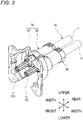
Fig. 2 is an exploded perspective view of the connector illustrated inFig. 1 ; -
Fig. 3 is a perspective view of the connector excluding an outer housing main body and an inner housing main body illustrated inFig. 2 ; -
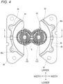
Fig. 4 is a front view of the connector illustrated inFig. 3 ; -
Fig. 5 is an enlarged view of a portion B inFig. 4 ; -
Fig. 6 is a cross-sectional view taken along a line A-A ofFig. 4 ; -
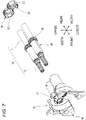
Fig. 7 is an exploded perspective view of the connector illustrated inFig. 3 ; -
Fig. 8 is an exploded perspective view of a second housing illustrated inFig. 7 ; -
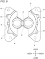
Fig. 9 is a front view of a metal holder illustrated inFig. 8 ; -
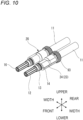
Fig. 10 is a view corresponding to a terminal-equipped electric wire to which a heat transfer member illustrated inFig. 7 is externally mounted, and is a perspective view illustrating a state in which the heat transfer member is compressed and deformed; and -
Fig. 11 is an exploded perspective view of the terminal-equipped electric wire to which the heat transfer member illustrated inFig. 7 is externally mounted. - Hereinafter, a connector 1 according to an embodiment of the presently disclosed subject matter will be described with reference to the drawings. The connector 1 is a connector that is installed in a vehicle such as a plug-in hybrid vehicle or an electric vehicle and is connected to an electric wire extending from a battery mounted on the vehicle. The connector 1 is also called a charging inlet. By fitting a mating connector (a so-called charging gun) into a fitting recess 63 (see
Fig. 1 and the like) of the connector 1, electric power is supplied from the outside of the vehicle to the battery, and the battery is charged. - Hereinafter, for convenience of description, as illustrated in
Fig. 1 and the like, a "front-rear direction", a "width direction", an "upper-lower direction", "upper", "lower", "front", and "rear" directions are defined. The "front-rear direction", the "width direction", and the "upper-lower direction" are orthogonal to each other. The front-rear direction coincides with a fitting direction of the connector 1 and the mating connector (not illustrated), a front side in the fitting direction (a side approaching the mating connector) as viewed from the connector 1 is referred to as a "front side", and a release side in the fitting direction (a side away from the mating connector) as viewed from the connector 1 is referred to as a "rear side". - As illustrated in
Figs. 1 and5 , the connector 1 includes a pair of terminal-equippedelectric wires 10, and ahousing 90 that accommodatesterminals 12 of the pair of terminal-equippedelectric wires 10 and holds the pair of terminal-equippedelectric wires 10. In the pair of terminal-equippedelectric wires 10, oneend portions 11c of the pair ofelectric wires 11 are connected to the pair ofterminals 12, respectively. The other end portions of the pair ofelectric wires 11 are connected to a battery (not illustrated). Each of theelectric wires 11 includes aconductor core wire 11a and acoating 11b made of an insulating resin and covering theconductor core wire 11a (seeFig. 6 ). Hereinafter, the components constituting the connector 1 will be described in order. - First, the pair of
terminals 12 will be described. In the present embodiment, the pair ofterminals 12 have the same shape. Each of the pair ofterminals 12 is made of metal, and as illustrated inFig. 6 , has a stepped columnar portion including asmall diameter portion 13 and alarge diameter portion 14 positioned on a rear side of thesmall diameter portion 13. Anannular step portion 15 is formed at a boundary portion between thesmall diameter portion 13 and the large diameter portion 14 (seeFig. 6 ). A C-ring 18 is provided in thestep portion 15. The pair ofterminals 12 are locked to aresin holder 30 by increasing diameters of the C-rings 18 in theresin holder 30, which will be described later. - Each of the
small diameter portions 13 is integrally provided with a cylindricalfemale terminal portion 16 protruding forward from a front end surface of thesmall diameter portion 13. Of the pair ofterminals 12, thefemale terminal portion 16 of oneterminal 12 functions as an anode side terminal, and thefemale terminal portion 16 of theother terminal 12 functions as a cathode side terminal. At the time of fitting the connector 1 and the mating connector, thefemale terminal portion 16 of the oneterminal 12 and thefemale terminal portion 16 of theother terminal 12 are respectively connected to a male terminal portion on an anode side and a male terminal portion on a cathode side of the mating connector. - An electric
wire connection portion 17 connected to the oneend portion 11c of theelectric wire 11 is provided at a rear end portion of the large diameter portion 14 (seeFig. 6 ). Specifically, theconductor core wire 11a exposed at the oneend portion 11c of theelectric wire 11 is connected to the electricwire connection portion 17. As a result, theterminal 12 and the oneend portion 11c of theelectric wire 11 are electrically connected to each other. - As illustrated in
Fig. 6 , an annular groove recessed radially inward is formed on an outer peripheral surface of thelarge diameter portion 14, and an O-ring 91 is mounted on the annular groove. The pair ofterminals 12 have been described above. - Next, the
housing 90 will be described. In the present embodiment, as illustrated inFigs. 1 and2 , thehousing 90 includes abase holder 50, arear holder 80, an inner housingmain body 60, and an outer housingmain body 70. Each of thebase holder 50, therear holder 80, the inner housingmain body 60, and the outer housingmain body 70 is a frame component of thehousing 90, and constitutes a part of an outer surface of thehousing 90. Hereinafter, the components constituting thehousing 90 will be described in order. - First, the
base holder 50 will be described. Thebase holder 50 has a function of holding the pair of terminal-equippedelectric wires 10 in a state of being insulated from each other at intervals in the width direction. As illustrated inFigs. 6 to 8 , thebase holder 50 includes theresin holder 30 which is a resin molded product, and ametal holder 40 which is a metal molded product. - The
resin holder 30 has functions of absorbing and dissipating heat generated in the pair ofterminals 12 and insulating and protecting the pair ofterminals 12. In particular, as illustrated inFig. 8 , theresin holder 30 integrally includes a pair of terminal holdingportions 31 aligned in the width direction and a connectingportion 32 connecting the pair of terminal holdingportions 31 in the width direction. As illustrated inFigs. 6 and8 , each of theterminal holding portions 31 has a stepped cylindrical shape extending in the front-rear direction, which includes asmall diameter portion 33 and alarge diameter portion 34. In theresin holder 30, a cross section of thesmall diameter portion 33 cut along the upper-lower direction and the width direction has a substantially perfect circular shape, and a cross section of thelarge diameter portion 34 cut along the upper-lower direction and the width direction has a substantially elliptical shape. - As illustrated in
Fig. 6 , aheat transfer member 20, which will be described later, is disposed inside eachlarge diameter portion 34. An annular groove recessed radially inward is formed on an outer peripheral surface of a rear end portion of thelarge diameter portion 34, and an O-ring 92 is mounted on the annular groove. - The connecting
portion 32 connects thelarge diameter portions 34 of the pair of terminal holdingportions 31. The pair ofterminals 12 are inserted into the pair of terminal holdingportions 31 from the rear side (see alsoFig. 8 ). Aprotrusion portion 35 protruding upward is provided on an outer peripheral surface on an upper side of the connectingportion 32, and aprotrusion portion 35 protruding downward is provided on an outer peripheral surface on a lower side of the connectingportion 32. Theprotrusion portions 35 have a function of preventing theresin holder 30 from falling off themetal holder 40. - The
metal holder 40 is assembled to theresin holder 30 from the rear side, and has a function of absorbing and dissipating heat generated in the pair ofterminals 12. As illustrated inFig. 8 , themetal holder 40 integrally includes a pair oftubular portions 41 aligned in the width direction and connectingportions 42 connecting the pair oftubular portions 41 in the width direction. - As illustrated in
Figs. 6 and8 , thetubular portion 41 has a stepped cylindrical shape extending in the front-rear direction, which includes asmall diameter portion 41b and alarge diameter portion 41a. As illustrated inFig. 9 , in themetal holder 40, a tubular hole of thetubular portion 41 has a substantially elliptical shape. In other words, themetal holder 40 has a substantially elliptical inner peripheral shape. - A front end portion of the
large diameter portion 41a is integrally provided with a pair of firstside wall portions 43 extending forward from both end portions of the front end portion of thelarge diameter portion 41a in the width direction. The pair of firstside wall portions 43 have an outer peripheral shape corresponding to an outer peripheral shape formed by the pair oflarge diameter portions 34 and the connectingportion 32 of theresin holder 30, and can be attached to theresin holder 30 so as to cover the outer peripheral surfaces of the pair oflarge diameter portions 34 and the connectingportion 32. - Front end portions of the pair of first
side wall portions 43 are integrally provided with a pair of first extendingportions 44 extending outward in the width direction from the front end portions of the pair of firstside wall portions 43 and a pair of secondside wall portions 45 extending forward from extending end portions of the pair of first extendingportions 44. The pair of secondside wall portions 45 have an outer peripheral shape corresponding to an outer peripheral shape of atubular portion 61 of the inner housingmain body 60, which will be described later. - Front end portions of the pair of second
side wall portions 45 are integrally provided with a pair of second extendingportions 46 extending outward in the width direction from the front end portions of the pair of secondside wall portions 45 and a pair of thirdside wall portions 47 extending forward from the extending end portions of the pair of second extendingportions 46.Bolt insertion holes 46a penetrating in the front-rear direction are formed at a plurality of locations (four locations in the present embodiment) in the pair of second extendingportions 46. Bolts (not illustrated) for assembling thehousing 90 are inserted into thebolt insertion holes 46a. - Front end portions of the pair of third
side wall portions 47 are integrally provided withflange portions 48 that extend outward in the width direction from the front end portions of the pair of thirdside wall portions 47. Bolt insertion holes 49 penetrating in the front-rear direction are formed at a plurality of locations (four locations in the present embodiment) in theflange portions 48. Bolts (not illustrated) for fixing the connector 1 to an attachment target portion of the connector 1 are inserted into the bolt insertion holes 49. - Next, the
rear holder 80 will be described. Therear holder 80 is assembled to thebase holder 50 from the rear side and has a function of holding the pair of terminal-equippedelectric wires 10 in a state of being spaced apart from each other in the width direction. Therear holder 80 is a resin molded product and integrally includes atubular portion 81 extending in the front-rear direction and arear wall portion 82 closing a rear opening of thetubular portion 81. - The
tubular portion 81 has an outer peripheral shape corresponding to outer peripheral shapes of the pair of tubular portions 41 (specifically, thesmall diameter portion 41b) of themetal holder 40, and can be mounted to a rear end portion of the metal holder 40 (that is, the base holder 50) so as to cover outer peripheral surfaces of the rear end portions of the pair oftubular portions 41. Therear wall portion 82 is provided with a pair of electric wire insertion holes 83 that are arranged in the width direction and penetrate in the front-rear direction, corresponding to the pair oftubular portions 41. The pair ofelectric wires 11 are inserted into the pair of electric wire insertion holes 83 (seeFig. 6 ). - Next, the inner housing
main body 60 will be described. The inner housingmain body 60 is assembled from the front side to the pair of secondside wall portions 45 of themetal holder 40, and also functions as the fitting recess 63 (see alsoFig. 1 ) of the connector 1. The inner housingmain body 60 is a resin molded product, and integrally includes atubular portion 61 having a cylindrical shape and extending in the front-rear direction, and a rear wall portion (not illustrated) closing a rear opening of thetubular portion 61. Thetubular portion 61 and the rear wall portion define thefitting recess 63 that is open forward and is recessed rearward. - A pair of cylindrical female terminal
accommodating portions 64 are provided on the rear wall portion so as to protrude forward, corresponding to the femaleterminal portions 16 of the pair of terminals 12 (seeFigs. 1 and2 ). Each of the femaleterminal accommodating portions 64 is positioned in thefitting recess 63 and has an internal space penetrating in the front-rear direction. - As illustrated in
Fig. 2 , anannular flange portion 65 protruding outward in a radial direction of thetubular portion 61 is provided at a position on the rear side of a center of an outer peripheral surface of thetubular portion 61 in the front-rear direction. Theflange portion 65 is provided withbolt insertion portions 66 at a plurality of locations (four locations in the present embodiment) in the peripheral direction corresponding to thebolt insertion holes 46a of the second extendingportions 46 of themetal holder 40. Abolt insertion hole 67 penetrating in the front-rear direction is formed in each of thebolt insertion portions 66. A bolt (not illustrated) for assembling thehousing 90 is inserted into thebolt insertion hole 67. - Next, the outer housing
main body 70 will be described. The outer housingmain body 70 is assembled to thetubular portion 61 of the inner housingmain body 60 from the front side, and has a function of fixing theentire housing 90 to the attachment target portion (not illustrated) of the connector 1 provided in the vehicle. The outer housingmain body 70 is a resin molded product, and has atubular portion 71 having a cylindrical shape and extending in the front-rear direction. Thetubular portion 71 can be attached to thetubular portion 61 from the front side so as to cover the outer peripheral surface of thetubular portion 61 of the inner housingmain body 60. - An
annular flange portion 72 protruding outward in a radial direction of thetubular portion 71 is provided at a position on the rear side of a center of an outer peripheral surface of thetubular portion 71 in the front-rear direction. Theflange portion 72 has a rectangular outer peripheral shape as viewed in the front-rear direction. Bolt insertion holes 73 penetrating in the front-rear direction are formed in four corner portions of theflange portion 72, corresponding to the bolt insertion holes 49 of theflange portion 48 of themetal holder 40, respectively. Bolts (not illustrated) for fixing the connector 1 to the attachment target portion of the connector 1 are inserted into the bolt insertion holes 73. The components constituting the frame component of thehousing 90 have been described above. - Next, the pair of
heat transfer members 20 will be described. Eachheat transfer member 20 is made of a material that has elasticity and an insulating property and is excellent in a heat transfer property, and has a functions of transferring heat from the terminal 12 to thebase holder 50. As illustrated inFigs. 7 and11 (in particular,Fig. 11 ), eachheat transfer member 20 includes atubular portion 21 having a substantially cylindrical and extending in the front-rear direction, and atubular hole 22 penetrating in the front-rear direction.Slits 23 extending in the front-rear direction are provided on an outer peripheral surface and an inner peripheral surface of thetubular portion 21. - Compression and deformation of the
heat transfer member 20 is assisted by theslits 23. Specifically, as illustrated inFig. 10 , when theheat transfer member 20 is compressed and deformed, portions of thetubular portion 21 that sandwich theslits 23 in the peripheral direction are folded back so as to slip into cuts of theslits 23 with theslits 23 as a base point. Thus, a folded-back portion 24 is formed in the tubular portion 21 (this point will be described later). Theheat transfer member 20 has been described above. - Next, a procedure for assembling the connector 1 will be described. First, the
metal holder 40 is mounted to theresin holder 30. Therefore, themetal holder 40 is attached to theresin holder 30 from the rear side so that the pair of firstside wall portions 43 thereof cover the outer peripheral surfaces of the pair oflarge diameter portions 34 and the connectingportion 32 of the resin holder 30 (seeFigs. 6 and7 ). In this way, thebase holder 50 is obtained by mounting themetal holder 40 to theresin holder 30. As preparation for mounting themetal holder 40 to theresin holder 30, the rubber O-ring 92 is mounted to each of the annular grooves of the pair oflarge diameter portions 34 of theresin holder 30. - In a state where the mounting is completed, as illustrated in
Fig. 5 , theprotrusion portions 35 of theresin holder 30 are pressed into contact with the connectingportions 42 of themetal holder 40. Specifically, theprotrusion portion 35 on the upper side presses the connectingportion 42 on the upper side upward, and theprotrusion portion 35 on the lower side presses the connectingportion 42 on the lower side downward. This prevents theresin holder 30 from falling off from themetal holder 40. - In a state where the
metal holder 40 is completely mounted on theresin holder 30, as illustrated inFig. 6 , the O-rings 92 are pressed and held between an outer peripheral surface of theresin holder 30 and an inner peripheral surface (specifically, the first side wall portions 43) of themetal holder 40. - Before or after mounting of the
metal holder 40 to theresin holder 30, the pair ofheat transfer members 20 are mounted to the pair of terminal-equippedelectric wires 10 to which the pair ofterminals 12 are connected to the oneend portions 11c of the pair ofelectric wires 11. Therefore, as illustrated inFig. 11 , the pair ofheat transfer members 20 are mounted so as to be in close contact with the electricwire connection portions 17 of theterminals 12 and the oneend portions 11c of theelectric wires 11 in the pair of terminal-equippedelectric wires 10 from the front side (see alsoFig. 7 ). The pair ofheat transfer members 20 are mounted so that theconductor core wires 11a of the pair ofelectric wires 11 are not exposed. The pair ofheat transfer members 20 may be mounted to the pair of terminal-equippedelectric wires 10 from the rear side, as long as the pair ofheat transfer members 20 are in close contact with connection portions between theterminals 12 and theelectric wires 11. - In a state where the mounting of the pair of
heat transfer members 20 to the pair of terminal-equippedelectric wires 10 is completed, since each of theheat transfer members 20 has the elasticity, the heat transfer member is in close contact with the terminal-equippedelectric wire 10 corresponding to a stepped shape of outer surfaces of the connection portion between the terminal 12 and theelectric wire 11 and thecoating 11b of theelectric wire 11. - When the mounting of the
metal holder 40 to theresin holder 30 is completed and the mounting of the pair ofheat transfer members 20 to the pair of terminal-equippedelectric wires 10 is completed, the pair ofterminals 12 of the pair of terminal-equippedelectric wires 10 are then inserted into thebase holder 50. For this reason, as preparation thereof, as illustrated inFigs. 7 and11 , thecoatings 11b of the pair ofelectric wires 11 of the pair of terminal-equippedelectric wires 10 are inserted into the pair of electric wire insertion holes 83 of therear holder 80 from the front side, and then annularrubber packings 93 are inserted into thecoatings 11b of the pair of electric wires from the front side so as to be adjacent to the front side of the rear wall portion of therear holder 80, respectively. Further, the O-rings 91 (seeFig. 6 ) made of rubber are mounted to the annular grooves of the pair ofterminals 12. - Next, the pair of
terminals 12 are inserted into the pair of terminal holdingportions 31 of theresin holder 30 in thebase holder 50 from the rear side. This insertion is continued until thesmall diameter portions 13 and the femaleterminal portions 16 of the pair ofterminals 12 protrude forward from the front ends of the pair of terminal holdingportions 31 and the pair ofterminals 12 are locked to inner peripheral surfaces of the pair of terminal holdingportions 31 by the C-rings 18. In a state where the insertion is completed (that is, a state where the insertion of the pair of terminal-equippedelectric wires 10 into thebase holder 50 is completed), as illustrated inFig. 6 , the O-rings 91 attached to theterminals 12 are respectively pressed into contact with the inner peripheral surfaces of thesmall diameter portions 33 of theterminal holding portions 31. - During the insertion of the pair of terminal-equipped
electric wires 10 into thebase holder 50, theheat transfer members 20 are pressed against the inner peripheral surface of thebase holder 50 and deformed to be compressed. At this time, theheat transfer member 20 is folded back so that the portions of thetubular portion 21 that sandwich theslits 23 in the peripheral direction slip into the cuts of theslits 23 with theslits 23 as a base point. As a result, the folded-back portion 24 is formed at a portion where theslits 23 of thetubular portion 21 are provided (seeFig. 10 ). When the insertion of the pair of terminal-equippedelectric wires 10 into thebase holder 50 is completed, theheat transfer members 20 are pressed into contact with both the outer peripheral surfaces of the terminal-equippedelectric wires 10 and the inner peripheral surface of the base holder 50 (in particular, the metal holder 40). In other words, theheat transfer members 20 are disposed in a compressed and deformed state so as to be in close contact between outer peripheral surfaces of the electricwire connection portions 17 of theterminals 12 and the oneend portions 11c of theelectric wires 11 and the inner peripheral surface of the base holder 50 (the resin holder 30), respectively. - When the insertion of the pair of
terminals 12 into thebase holder 50 is completed, therear holder 80 is then attached to thebase holder 50. Therefore, by pressing therear holder 80 toward the front side and moving the pair ofpackings 93 positioned on the front side of therear holder 80 and therear holder 80 to the front side with respect to the pair ofelectric wires 11, thetubular portions 81 of therear holder 80 are attached to a rear end portion of the base holder 50 (specifically, the metal holder 40) (seeFigs. 2 to 3 and6 ). - In a state where the
rear holder 80 is completely mounted on thebase holder 50, as illustrated inFig. 6 , each packing 93 is pressed and held between the inner peripheral surface of themetal holder 40 of thebase holder 50 and the outer peripheral surface of the electric wire 11 (thecoating 11b). As a result, due to a water stopping function of the pair of O-rings 91, the pair of O-rings 92, and the pair ofpackings 93, entry of water into internal spaces of the pair of terminal holding portions 31 (specifically, the connection portions between theterminals 12 and the electric wires 11) from the outside is suppressed. Further, the pair ofterminals 12 are held by theresin holder 30 of thebase holder 50 in a state of being insulated from each other at intervals in the width direction, and the pair ofelectric wires 11 extending rearward from the pair ofterminals 12 are held by therear holder 80 in a state of being spaced apart from each other in the width direction. - When the mounting of the
rear holder 80 to thebase holder 50 is completed, the outer housingmain body 70 is then mounted to the inner housing main body 60 (seeFig. 1 ). Therefore, the outer housingmain body 70 is mounted to the inner housingmain body 60 from the front side so that thetubular portion 71 of the outer housingmain body 70 covers the outer peripheral surface of thetubular portion 61 of the inner housingmain body 60. In a state where the mounting is completed, a rear end surface of thetubular portion 71 of the outer housingmain body 70 is in contact with a front end surface of theflange portion 65 of the inner housingmain body 60. - When the mounting of the outer housing
main body 70 to the inner housingmain body 60 is completed, a plurality of (four in the present embodiment) bolts (not illustrated) are then inserted into the plurality ofbolt insertion holes 46a of thebase holder 50 and the plurality of bolt insertion holes 67 of the inner housingmain body 60 from the rear side, and fastened to a plurality of fastening positions (not illustrated) provided in the outer housingmain body 70, as illustrated inFig. 2 . Accordingly, thebase holder 50 and the inner housingmain body 60 are fastened to the outer housingmain body 70, so that thebase holder 50, therear holder 80, the inner housingmain body 60, and the outer housingmain body 70 constituting the frame component of thehousing 90 are integrated. As a result, the assembly of the connector 1 is completed, and the connector 1 illustrated inFig. 1 is obtained. - The connector 1 for which the assembly has been completed is fastened and fixed to the attachment target portion (not illustrated) of the connector 1 provided in the vehicle by using a plurality of (four in the present embodiment) bolts (not illustrated) inserted into the bolt insertion holes 49 of the
metal holder 40 in thebase holder 50 and the plurality of bolt insertion holes 73 of the outer housingmain body 70. - When the battery (not illustrated) mounted on the vehicle is charged, a mating connector (so-called charging gun) is fitted into the exposed
fitting recess 63 of the connector 1 fixed to the attachment target portion of the vehicle. As a result, electric power is supplied to the battery from the outside of the vehicle via the mating connector, the connector 1, and the pair of terminal-equippedelectric wires 10 in this order, and the battery is charged. - Next, the operation of providing the
base holder 50 including theresin holder 30 and themetal holder 40 and theheat transfer member 20 to the connector 1 will be described. As described above, when the battery is charged using the connector 1, the temperatures of the pair ofterminals 12 in the connector 1 rise due to Joule heat caused by the energization. In particular, when the battery is rapidly charged, a large current passes through the pair ofterminals 12 in a short time, and therefore a degree of a rise in the temperatures of the pair ofterminals 12 per unit time is likely to increase. - In this regard, in the present embodiment, the heat generated in the terminal 12 is mainly transmitted to the
resin holder 30 via theheat transfer member 20, and is absorbed by themetal holder 40. In addition, the heat generated in the terminal 12 is transmitted to and absorbed by themetal holder 40 via theheat transfer member 20. Further, the heat transmitted to themetal holder 40 is transmitted to and absorbed by the attachment target portion (not illustrated) of the connector 1 provided in the vehicle via the bolts (not illustrated) inserted through theflange portion 48 and thebolt insertion hole 49 of themetal holder 40. The heat absorbed by the base holder 50 (particularly, the metal holder 40) and the attachment target portion are respectively dissipated to the outside through the outer surface (the surface exposed to the outside) of thebase holder 50 and the outer surface of the attachment target portion. As a result, the rise in the temperature of the terminal 12 is suppressed. - The
base holder 50 includes theresin holder 30 and themetal holder 40. In general, when a metal member and a resin member are compared in the same volume, a heat capacity of the metal member is larger than a heat capacity of the resin member due to the fact that a density of the metal is higher than a density of the resin. On the other hand, the terminal 12, the electricwire connection portion 17 of the terminal 12 and the oneend portion 11c of theelectric wire 11 must be insulated and protected. Therefore, theresin holder 30 is externally mounted to the terminal-equippedelectric wire 10 so as to hold the terminal 12 and cover the connection portion between the terminal 12 and theelectric wire 11, and themetal holder 40 is externally mounted to theresin holder 30. - Accordingly, the
base holder 50 can insulate and protect the terminal 12, the electricwire connection portion 17 of the terminal 12 and the oneend portion 11c of theelectric wire 11 while maintaining an excellent heat capacity. From a viewpoint of a heat dissipation performance, the material constituting themetal holder 40 is not necessarily limited to metal, and may be another material as long as it has an appropriate heat capacity. In addition, from a viewpoint of insulation protection, the material constituting theresin holder 30 is not necessarily limited to resin, and may be other materials as long as the terminal 12, the electricwire connection portion 17 of the terminal 12 and the oneend portion 11c of theelectric wire 11 can be insulated and protected. From the viewpoint of the insulation protection, an insulating coating agent that does not impair the heat capacity may be applied to themetal holder 40. - The larger the heat capacity of the
metal holder 40, the slower the rise in the temperature of themetal holder 40 that absorbs heat generated in the terminal 12. Therefore, for example, even when the Joule heat generated in the terminal 12 is large as in the case of the rapid charging, the temperature of themetal holder 40 can slowly rise by using themetal holder 40 having a large heat capacity, and as a result, the temperature of the terminal 12 can also slowly rise. - Noted that the temperature of the
metal holder 40 raised by the rapid charging decreases due to natural heat dissipation after the rapid charging is finished. At this time, as the heat capacity of themetal holder 40 becomes larger, the temperature of themetal holder 40 slowly decreases (that is, a relatively long time is required until the temperature of themetal holder 40 returns to a normal temperature). However, it is unlikely that the connector 1 is not used for any purpose other than the charging of the battery, and the rapid charging is started again after a short period of time after the completion of the rapid charging. Therefore, even if the temperature of themetal holder 40 after the completion of the rapid charging slowly decreases (even if a relatively long time is required until the temperature of themetal holder 40 returns to the normal temperature), there is no problem in light of the function of the connector 1. - According to the connector 1 of the present embodiment, the
heat transfer member 20 is disposed in the compressed and deformed state so as to be in close contact between the outer peripheral surface of the electricwire connection portion 17 of the terminal 12 and the oneend portion 11c of theelectric wire 11 and the inner peripheral surface of thebase holder 50, so that the heat generated in the terminal 12 at the time of energization can be absorbed by theheat transfer member 20 having a large heat capacity. Accordingly, even when a heat generation amount of the terminal 12 per unit time is large as in the case of the rapid charging, theheat transfer member 20 can suppress a rapid rise in the operating temperature of the terminal 12, and can make the operating temperature of the terminal 12 slowly rise. Thebase holder 50 further includes theresin holder 30 that is externally mounted on the electricwire connection portion 17 of the terminal 12 and the oneend portion 11c of theelectric wire 11, and themetal holder 40 that is externally mounted on theresin holder 30. As a result, the connection portion between the terminal 12 and theelectric wire 11 is insulated and protected from themetal holder 40 by theresin holder 30. The heat absorbed by theheat transfer member 20 is efficiently transferred from the inside to the outside of the connector 1. - According to the connector 1 of the present embodiment, since the inner peripheral shape of the
metal holder 40 has the substantially elliptical shape, the compression and deformation of theheat transfer member 20 having a substantially cylindrical shape can be adjusted to an appropriate state. Specifically, since theheat transfer member 20 is attached to the terminal-equippedelectric wire 10 having the stepped shape of the connection portion between the terminal 12 and theelectric wire 11 and thecoating 11b of theelectric wire 11 on the outer surface, the compression and deformation of theheat transfer member 20 does not mean that theheat transfer member 20 is deformed so as to be concentrically reduced in a diameter. That is, normally, theheat transfer member 20 is not compressed and deformed as intended. However, by making the inner peripheral shape of themetal holder 40 elliptical, it is possible to release the thickness of the portion of theheat transfer member 20 to be attached to the stepped portion of the terminal-equippedelectric wire 10 to a target position. Therefore, the connector 1 according to the present embodiment can adjust the compression and deformation of theheat transfer member 20 to an appropriate state. - Similarly, even when the terminal-equipped
electric wire 10 has the stepped shape on the outer surface of the connection portion between the terminal 12 and theelectric wire 11, the inner peripheral shape of themetal holder 40 has a substantially elliptical shape, so that the compression and deformation of theheat transfer member 20 is adjusted to an appropriate state. In addition, theheat transfer member 20 is provided with theslit 23 for assisting the compression and deformation of thetubular portion 21. Therefore, in the connector 1 according to the present embodiment, theheat transfer member 20 can be appropriately compressed and deformed so as to be in close contact with both the outer peripheral surfaces of the electricwire connection portion 17 of the terminal 12 and the oneend portion 11c of theelectric wire 11 and the inner peripheral surface of thebase holder 50. - In the present embodiment, the
slit 23 extending in the front-rear direction is provided in thetubular portion 21, but the present disclosure is not limited thereto, and theslit 23 may have another shape as long as the compression and deformation of theheat transfer member 20 is assisted. For example, theslit 23 may be provided in thetubular portion 21 along the peripheral direction of theheat transfer member 20. - According to the connector 1 of the present embodiment, the
metal holder 40 has theflange portion 48 that is fastened and fixed to the attachment target portion (not illustrated) of the connector 1 provided in the vehicle. Accordingly, the heat generated in the terminal 12 is transmitted to themetal holder 40 via theheat transfer member 20, and the heat is transmitted to and absorbed by the attachment target portion (not illustrated) via theflange portion 48 of themetal holder 40 and the bolt (not illustrated) inserted through thebolt insertion hole 49. - As a result, the connector 1 according to the present embodiment suppresses an excessive rise in the operating temperature of the terminal 12 and has the excellent heat dissipation performance.
- As another effect, in the connector 1 according to the present embodiment, since the
heat transfer member 20 has the elasticity, the terminal 12 can be protected from an impact caused by an external factor. - While the presently disclosed subject matter has been described with reference to certain exemplary embodiments thereof, the scope of the presently disclosed subject matter is not limited to the exemplary embodiments described above, and it will be understood by those skilled in the art that various changes and modifications may be made therein without departing from the scope of the presently disclosed subject matter as defined by the appended claims.
- According to an aspect of the embodiments described above, a connector (1) includes a terminal-equipped electric wire (10) having a terminal (12) connected to an end portion (for example, one
end portion 11c) of an electric wire (11), housing (90) configured to accommodate the terminal and to hold the terminal-equipped electric wire and a heat transfer member (20) having elasticity. The housing (90) includes a first housing (for example, inner housing main body 60) having a terminal accommodating portion (for example, female terminal accommodating portion 64) configured to accommodate the terminal, and a second housing (for example, base holder 50) configured to hold the terminal-equipped electric wire. The second housing (for example, base holder 50) includes a resin holder (30) configured to be externally mounted on an electric wire connection portion (17) of the terminal configured to be connected to the electric wire and the end portion (for example, oneend portion 11c) of the electric wire, and a metal holder (40) configured to externally mounted on the resin holder. The heat transfer member (20) is disposed in a compressed and deformed state between an outer circumferential surface of at least one of the electric wire connection portion (17) of the terminal and the end portion (for example, oneend portion 11c) of the electric wire and an inner circumferential surface of the second housing (for example, base holder 50), the heat transfer member (20) contacting in a pressed manner the outer circumferential surface of the at least one of the electric wire connection portion (17) and the end portion (for example, oneend portion 11c) of the electric wire and the inner circumferential surface of the second housing (for example, base holder 50). - The heat transfer member (20) may be disposed between outer circumferential surfaces of the electric wire connection portion (17) and the end portion (for example, one
end portion 11c) of the electric wire and the inner circumferential surface of the second housing (for example, base holder 50). - The heat transfer member (20) may have a tubular shape.
- The second housing (base holder 50) may have an inner peripheral shape corresponding to an outer peripheral shape of the heat transfer member (20) that is compressed and deformed.
- The metal holder (40) may include a flange portion (48) extending toward a fixing target member to which the connector (1) is to be fixed, the flange portion (48) being configured to be fastened to the fixing target member.
- The heat transfer member (20) may have a slit (23) configured to assist the compression and deformation of the heat transfer member (20).
- The connector according to the presently disclosed subject matter will be described below. The heat transfer member having the elasticity is disposed in the compressed and deformed state so as to be in close contact between the outer peripheral surface of at least one of the electric wire connection portion of the terminal and the end portion of the electric wire and the inner peripheral surface of the second housing that holds the terminal-equipped electric wire. Accordingly, by absorbing the heat generated at the terminal at the time of energization by the heat transfer member having a large heat capacity, even when a heat generation amount of the terminal per unit time is large as in the case of the rapid charging, a rapid rise in an operating temperature of the terminal can be suppressed, and the operating temperature of the terminal can slowly rise. Further, the second housing includes the resin holder that is externally mounted on the electric wire connection portion of the terminal and the end portion of the electric wire, and the metal holder that is externally mounted on the resin holder. As a result, the electric wire connection portion of the terminal and the end portion of the electric wire are insulated and protected from the metal holder by the resin holder. The heat absorbed by the heat transfer member is efficiently transferred from the inside to the outside of the connector. Therefore, the connector of the presently disclosed subject matter suppresses an excessive rise in the operating temperature of the terminal and has an excellent heat dissipation performance.
Claims (6)
- A connector (1) comprising:a terminal-equipped electric wire (10) having a terminal (12) connected to an end portion (11c) of an electric wire (11);housing (90) configured to accommodate the terminal and to hold the terminal-equipped electric wire; anda heat transfer member (20) having elasticity,wherein the housing (90) includes a first housing (60) having a terminal accommodating portion (64) configured to accommodate the terminal, and a second housing (50) configured to hold the terminal-equipped electric wire,wherein the second housing (50) includes a resin holder (30) configured to be externally mounted on an electric wire connection portion (17) of the terminal configured to be connected to the electric wire and the end portion (11c) of the electric wire, and a metal holder (40) configured to be externally mounted on the resin holder, andwherein the heat transfer member (20) is disposed in a compressed and deformed state between an outer circumferential surface of at least one of the electric wire connection portion (17) of the terminal and the end portion (11c) of the electric wire and an inner circumferential surface of the second housing (50), the heat transfer member (20) contacting in a pressed manner the outer circumferential surface of the at least one of the electric wire connection portion (17) and the end portion (11c) of the electric wire and the inner circumferential surface of the second housing (50).
- The connector (1) according to claim 1,
wherein the heat transfer member (20) is disposed between outer circumferential surfaces of the electric wire connection portion (17) and the end portion (11c) of the electric wire and the inner circumferential surface of the second housing (50). - The connector (1) according to claim 1 or 2,
wherein the heat transfer member (20) has a tubular shape. - The connector (1) according to any one of claims 1 to 3,
wherein the second housing (50) has an inner peripheral shape corresponding to an outer peripheral shape of the heat transfer member (20) that is compressed and deformed. - The connector (1) according to any one of claims 1 to 4,
wherein the metal holder (40) includes a flange portion (48) extending toward a fixing target member to which the connector (1) is to be fixed, the flange portion (48) being configured to be fastened to the fixing target member. - The connector (1) according to any one of claims 1 to 5,
wherein the heat transfer member (20) has a slit (23) configured to assist the compression and deformation of the heat transfer member (20).
Applications Claiming Priority (1)
| Application Number | Priority Date | Filing Date | Title |
|---|---|---|---|
| JP2021124714A JP7348238B2 (en) | 2021-07-29 | 2021-07-29 | connector |
Publications (2)
| Publication Number | Publication Date |
|---|---|
| EP4125156A1 true EP4125156A1 (en) | 2023-02-01 |
| EP4125156B1 EP4125156B1 (en) | 2023-12-06 |
Family
ID=82780846
Family Applications (1)
| Application Number | Title | Priority Date | Filing Date |
|---|---|---|---|
| EP22187503.2A Active EP4125156B1 (en) | 2021-07-29 | 2022-07-28 | Connector |
Country Status (4)
| Country | Link |
|---|---|
| US (1) | US20230032999A1 (en) |
| EP (1) | EP4125156B1 (en) |
| JP (1) | JP7348238B2 (en) |
| CN (1) | CN115693239A (en) |
Families Citing this family (1)
| Publication number | Priority date | Publication date | Assignee | Title |
|---|---|---|---|---|
| JP7163865B2 (en) * | 2019-05-14 | 2022-11-01 | 株式会社オートネットワーク技術研究所 | Connection terminals and connectors |
Citations (5)
| Publication number | Priority date | Publication date | Assignee | Title |
|---|---|---|---|---|
| JP2017208247A (en) | 2016-05-19 | 2017-11-24 | 住友電装株式会社 | Charging inlet |
| US20190036270A1 (en) * | 2017-07-28 | 2019-01-31 | Yazaki Corporation | Connector |
| US20190322186A1 (en) * | 2018-04-24 | 2019-10-24 | Toyota Jidosha Kabushiki Kaisha | Connector |
| US20200212620A1 (en) * | 2018-12-27 | 2020-07-02 | Yazaki Corporation | Waterproof packing, waterproof connector and wire harness |
| US10756498B1 (en) * | 2019-03-22 | 2020-08-25 | Te Connectivity Corporation | Terminal heat exchanger for an electrical connector |
Family Cites Families (6)
| Publication number | Priority date | Publication date | Assignee | Title |
|---|---|---|---|---|
| JP4398948B2 (en) | 2006-03-23 | 2010-01-13 | 古河電気工業株式会社 | Electrical connector |
| CN203300912U (en) | 2013-07-02 | 2013-11-20 | 佛山市新基德电子厂有限公司 | Leakage protection plug with temperature protection |
| CN108306144B (en) | 2017-02-16 | 2019-10-01 | 番禺得意精密电子工业有限公司 | Electric connector combination |
| CN207082683U (en) | 2017-03-13 | 2018-03-09 | 深圳市沃尔核材股份有限公司 | charging socket with automatic cooling function |
| JP2018156843A (en) | 2017-03-17 | 2018-10-04 | 住友電装株式会社 | Female terminal |
| JP2020004630A (en) | 2018-06-29 | 2020-01-09 | 株式会社フジクラ | Charging connector |
-
2021
- 2021-07-29 JP JP2021124714A patent/JP7348238B2/en active Active
-
2022
- 2022-07-27 CN CN202210892894.4A patent/CN115693239A/en active Pending
- 2022-07-28 US US17/875,992 patent/US20230032999A1/en active Pending
- 2022-07-28 EP EP22187503.2A patent/EP4125156B1/en active Active
Patent Citations (5)
| Publication number | Priority date | Publication date | Assignee | Title |
|---|---|---|---|---|
| JP2017208247A (en) | 2016-05-19 | 2017-11-24 | 住友電装株式会社 | Charging inlet |
| US20190036270A1 (en) * | 2017-07-28 | 2019-01-31 | Yazaki Corporation | Connector |
| US20190322186A1 (en) * | 2018-04-24 | 2019-10-24 | Toyota Jidosha Kabushiki Kaisha | Connector |
| US20200212620A1 (en) * | 2018-12-27 | 2020-07-02 | Yazaki Corporation | Waterproof packing, waterproof connector and wire harness |
| US10756498B1 (en) * | 2019-03-22 | 2020-08-25 | Te Connectivity Corporation | Terminal heat exchanger for an electrical connector |
Also Published As
| Publication number | Publication date |
|---|---|
| JP7348238B2 (en) | 2023-09-20 |
| CN115693239A (en) | 2023-02-03 |
| JP2023019754A (en) | 2023-02-09 |
| EP4125156B1 (en) | 2023-12-06 |
| US20230032999A1 (en) | 2023-02-02 |
Similar Documents
| Publication | Publication Date | Title |
|---|---|---|
| US7828591B2 (en) | Connector for a device | |
| US7306475B2 (en) | Electrical connection construction | |
| US10205271B1 (en) | Connector | |
| EP4125156A1 (en) | Connector | |
| EP3611751B1 (en) | Conductive connection structure, multifunctional high-voltage connector and battery product | |
| JP7280234B2 (en) | connector | |
| WO2014175176A1 (en) | Connector | |
| EP4108510B1 (en) | Connector | |
| EP4108513A1 (en) | Connector | |
| CN114447849B (en) | Wire fixing structure and wire harness | |
| JPH0864306A (en) | Shield structure of direct mount shield connector for apparatus | |
| EP4125157B1 (en) | Temperature rise preventing connection terminal and method for its production. | |
| JP3947089B2 (en) | Conductive path with shielding function | |
| CN217983803U (en) | Connector and connector assembly | |
| WO2023095693A1 (en) | Shield connector | |
| US20240154350A1 (en) | Connector | |
| WO2023223910A1 (en) | Connector | |
| CN215911545U (en) | A switching subassembly and battery module for electric core | |
| CN218827741U (en) | Battery pack and vehicle | |
| CN219916962U (en) | Maintenance switch | |
| WO2024024622A1 (en) | Connector unit | |
| JP2023102653A (en) | connector | |
| CN118017260A (en) | Connector with a plurality of connectors | |
| JP2023077366A (en) | shield connector | |
| CN117096661A (en) | Connector with a plurality of connectors |
Legal Events
| Date | Code | Title | Description |
|---|---|---|---|
| PUAI | Public reference made under article 153(3) epc to a published international application that has entered the european phase |
Free format text: ORIGINAL CODE: 0009012 |
|
| STAA | Information on the status of an ep patent application or granted ep patent |
Free format text: STATUS: REQUEST FOR EXAMINATION WAS MADE |
|
| 17P | Request for examination filed |
Effective date: 20220728 |
|
| AK | Designated contracting states |
Kind code of ref document: A1 Designated state(s): AL AT BE BG CH CY CZ DE DK EE ES FI FR GB GR HR HU IE IS IT LI LT LU LV MC MK MT NL NO PL PT RO RS SE SI SK SM TR |
|
| STAA | Information on the status of an ep patent application or granted ep patent |
Free format text: STATUS: EXAMINATION IS IN PROGRESS |
|
| RAP3 | Party data changed (applicant data changed or rights of an application transferred) |
Owner name: YAZAKI CORPORATION |
|
| 17Q | First examination report despatched |
Effective date: 20230516 |
|
| GRAP | Despatch of communication of intention to grant a patent |
Free format text: ORIGINAL CODE: EPIDOSNIGR1 |
|
| STAA | Information on the status of an ep patent application or granted ep patent |
Free format text: STATUS: GRANT OF PATENT IS INTENDED |
|
| INTG | Intention to grant announced |
Effective date: 20230921 |
|
| GRAS | Grant fee paid |
Free format text: ORIGINAL CODE: EPIDOSNIGR3 |
|
| GRAA | (expected) grant |
Free format text: ORIGINAL CODE: 0009210 |
|
| STAA | Information on the status of an ep patent application or granted ep patent |
Free format text: STATUS: THE PATENT HAS BEEN GRANTED |
|
| AK | Designated contracting states |
Kind code of ref document: B1 Designated state(s): AL AT BE BG CH CY CZ DE DK EE ES FI FR GB GR HR HU IE IS IT LI LT LU LV MC MK MT NL NO PL PT RO RS SE SI SK SM TR |
|
| REG | Reference to a national code |
Ref country code: GB Ref legal event code: FG4D |
|
| REG | Reference to a national code |
Ref country code: CH Ref legal event code: EP |
|
| REG | Reference to a national code |
Ref country code: DE Ref legal event code: R096 Ref document number: 602022001225 Country of ref document: DE |
|
| REG | Reference to a national code |
Ref country code: IE Ref legal event code: FG4D |
|
| REG | Reference to a national code |
Ref country code: LT Ref legal event code: MG9D |
|
| PG25 | Lapsed in a contracting state [announced via postgrant information from national office to epo] |
Ref country code: GR Free format text: LAPSE BECAUSE OF FAILURE TO SUBMIT A TRANSLATION OF THE DESCRIPTION OR TO PAY THE FEE WITHIN THE PRESCRIBED TIME-LIMIT Effective date: 20240307 |
|
| REG | Reference to a national code |
Ref country code: NL Ref legal event code: MP Effective date: 20231206 |
|
| PG25 | Lapsed in a contracting state [announced via postgrant information from national office to epo] |
Ref country code: LT Free format text: LAPSE BECAUSE OF FAILURE TO SUBMIT A TRANSLATION OF THE DESCRIPTION OR TO PAY THE FEE WITHIN THE PRESCRIBED TIME-LIMIT Effective date: 20231206 |
|
| PG25 | Lapsed in a contracting state [announced via postgrant information from national office to epo] |
Ref country code: ES Free format text: LAPSE BECAUSE OF FAILURE TO SUBMIT A TRANSLATION OF THE DESCRIPTION OR TO PAY THE FEE WITHIN THE PRESCRIBED TIME-LIMIT Effective date: 20231206 |
|
| PG25 | Lapsed in a contracting state [announced via postgrant information from national office to epo] |
Ref country code: LT Free format text: LAPSE BECAUSE OF FAILURE TO SUBMIT A TRANSLATION OF THE DESCRIPTION OR TO PAY THE FEE WITHIN THE PRESCRIBED TIME-LIMIT Effective date: 20231206 Ref country code: GR Free format text: LAPSE BECAUSE OF FAILURE TO SUBMIT A TRANSLATION OF THE DESCRIPTION OR TO PAY THE FEE WITHIN THE PRESCRIBED TIME-LIMIT Effective date: 20240307 Ref country code: ES Free format text: LAPSE BECAUSE OF FAILURE TO SUBMIT A TRANSLATION OF THE DESCRIPTION OR TO PAY THE FEE WITHIN THE PRESCRIBED TIME-LIMIT Effective date: 20231206 Ref country code: BG Free format text: LAPSE BECAUSE OF FAILURE TO SUBMIT A TRANSLATION OF THE DESCRIPTION OR TO PAY THE FEE WITHIN THE PRESCRIBED TIME-LIMIT Effective date: 20240306 |