EP4125098A1 - A power cable assembly for a power distribution system having an integrated cooling system - Google Patents
A power cable assembly for a power distribution system having an integrated cooling system Download PDFInfo
- Publication number
- EP4125098A1 EP4125098A1 EP21188670.0A EP21188670A EP4125098A1 EP 4125098 A1 EP4125098 A1 EP 4125098A1 EP 21188670 A EP21188670 A EP 21188670A EP 4125098 A1 EP4125098 A1 EP 4125098A1
- Authority
- EP
- European Patent Office
- Prior art keywords
- power cable
- cable assembly
- cooling tube
- coolant
- cooling
- Prior art date
- Legal status (The legal status is an assumption and is not a legal conclusion. Google has not performed a legal analysis and makes no representation as to the accuracy of the status listed.)
- Pending
Links
Images



Classifications
-
- H—ELECTRICITY
- H01—ELECTRIC ELEMENTS
- H01B—CABLES; CONDUCTORS; INSULATORS; SELECTION OF MATERIALS FOR THEIR CONDUCTIVE, INSULATING OR DIELECTRIC PROPERTIES
- H01B7/00—Insulated conductors or cables characterised by their form
- H01B7/42—Insulated conductors or cables characterised by their form with arrangements for heat dissipation or conduction
- H01B7/421—Insulated conductors or cables characterised by their form with arrangements for heat dissipation or conduction for heat dissipation
- H01B7/423—Insulated conductors or cables characterised by their form with arrangements for heat dissipation or conduction for heat dissipation using a cooling fluid
-
- B—PERFORMING OPERATIONS; TRANSPORTING
- B60—VEHICLES IN GENERAL
- B60L—PROPULSION OF ELECTRICALLY-PROPELLED VEHICLES; SUPPLYING ELECTRIC POWER FOR AUXILIARY EQUIPMENT OF ELECTRICALLY-PROPELLED VEHICLES; ELECTRODYNAMIC BRAKE SYSTEMS FOR VEHICLES IN GENERAL; MAGNETIC SUSPENSION OR LEVITATION FOR VEHICLES; MONITORING OPERATING VARIABLES OF ELECTRICALLY-PROPELLED VEHICLES; ELECTRIC SAFETY DEVICES FOR ELECTRICALLY-PROPELLED VEHICLES
- B60L53/00—Methods of charging batteries, specially adapted for electric vehicles; Charging stations or on-board charging equipment therefor; Exchange of energy storage elements in electric vehicles
- B60L53/10—Methods of charging batteries, specially adapted for electric vehicles; Charging stations or on-board charging equipment therefor; Exchange of energy storage elements in electric vehicles characterised by the energy transfer between the charging station and the vehicle
- B60L53/14—Conductive energy transfer
- B60L53/18—Cables specially adapted for charging electric vehicles
-
- B—PERFORMING OPERATIONS; TRANSPORTING
- B60—VEHICLES IN GENERAL
- B60L—PROPULSION OF ELECTRICALLY-PROPELLED VEHICLES; SUPPLYING ELECTRIC POWER FOR AUXILIARY EQUIPMENT OF ELECTRICALLY-PROPELLED VEHICLES; ELECTRODYNAMIC BRAKE SYSTEMS FOR VEHICLES IN GENERAL; MAGNETIC SUSPENSION OR LEVITATION FOR VEHICLES; MONITORING OPERATING VARIABLES OF ELECTRICALLY-PROPELLED VEHICLES; ELECTRIC SAFETY DEVICES FOR ELECTRICALLY-PROPELLED VEHICLES
- B60L53/00—Methods of charging batteries, specially adapted for electric vehicles; Charging stations or on-board charging equipment therefor; Exchange of energy storage elements in electric vehicles
- B60L53/30—Constructional details of charging stations
- B60L53/302—Cooling of charging equipment
-
- H—ELECTRICITY
- H01—ELECTRIC ELEMENTS
- H01B—CABLES; CONDUCTORS; INSULATORS; SELECTION OF MATERIALS FOR THEIR CONDUCTIVE, INSULATING OR DIELECTRIC PROPERTIES
- H01B7/00—Insulated conductors or cables characterised by their form
- H01B7/02—Disposition of insulation
-
- H—ELECTRICITY
- H01—ELECTRIC ELEMENTS
- H01B—CABLES; CONDUCTORS; INSULATORS; SELECTION OF MATERIALS FOR THEIR CONDUCTIVE, INSULATING OR DIELECTRIC PROPERTIES
- H01B9/00—Power cables
- H01B9/006—Constructional features relating to the conductors
-
- H—ELECTRICITY
- H02—GENERATION; CONVERSION OR DISTRIBUTION OF ELECTRIC POWER
- H02B—BOARDS, SUBSTATIONS OR SWITCHING ARRANGEMENTS FOR THE SUPPLY OR DISTRIBUTION OF ELECTRIC POWER
- H02B1/00—Frameworks, boards, panels, desks, casings; Details of substations or switching arrangements
- H02B1/20—Bus-bar or other wiring layouts, e.g. in cubicles, in switchyards
-
- H—ELECTRICITY
- H02—GENERATION; CONVERSION OR DISTRIBUTION OF ELECTRIC POWER
- H02B—BOARDS, SUBSTATIONS OR SWITCHING ARRANGEMENTS FOR THE SUPPLY OR DISTRIBUTION OF ELECTRIC POWER
- H02B1/00—Frameworks, boards, panels, desks, casings; Details of substations or switching arrangements
- H02B1/56—Cooling; Ventilation
-
- Y—GENERAL TAGGING OF NEW TECHNOLOGICAL DEVELOPMENTS; GENERAL TAGGING OF CROSS-SECTIONAL TECHNOLOGIES SPANNING OVER SEVERAL SECTIONS OF THE IPC; TECHNICAL SUBJECTS COVERED BY FORMER USPC CROSS-REFERENCE ART COLLECTIONS [XRACs] AND DIGESTS
- Y02—TECHNOLOGIES OR APPLICATIONS FOR MITIGATION OR ADAPTATION AGAINST CLIMATE CHANGE
- Y02T—CLIMATE CHANGE MITIGATION TECHNOLOGIES RELATED TO TRANSPORTATION
- Y02T10/00—Road transport of goods or passengers
- Y02T10/60—Other road transportation technologies with climate change mitigation effect
- Y02T10/70—Energy storage systems for electromobility, e.g. batteries
-
- Y—GENERAL TAGGING OF NEW TECHNOLOGICAL DEVELOPMENTS; GENERAL TAGGING OF CROSS-SECTIONAL TECHNOLOGIES SPANNING OVER SEVERAL SECTIONS OF THE IPC; TECHNICAL SUBJECTS COVERED BY FORMER USPC CROSS-REFERENCE ART COLLECTIONS [XRACs] AND DIGESTS
- Y02—TECHNOLOGIES OR APPLICATIONS FOR MITIGATION OR ADAPTATION AGAINST CLIMATE CHANGE
- Y02T—CLIMATE CHANGE MITIGATION TECHNOLOGIES RELATED TO TRANSPORTATION
- Y02T10/00—Road transport of goods or passengers
- Y02T10/60—Other road transportation technologies with climate change mitigation effect
- Y02T10/7072—Electromobility specific charging systems or methods for batteries, ultracapacitors, supercapacitors or double-layer capacitors
-
- Y—GENERAL TAGGING OF NEW TECHNOLOGICAL DEVELOPMENTS; GENERAL TAGGING OF CROSS-SECTIONAL TECHNOLOGIES SPANNING OVER SEVERAL SECTIONS OF THE IPC; TECHNICAL SUBJECTS COVERED BY FORMER USPC CROSS-REFERENCE ART COLLECTIONS [XRACs] AND DIGESTS
- Y02—TECHNOLOGIES OR APPLICATIONS FOR MITIGATION OR ADAPTATION AGAINST CLIMATE CHANGE
- Y02T—CLIMATE CHANGE MITIGATION TECHNOLOGIES RELATED TO TRANSPORTATION
- Y02T90/00—Enabling technologies or technologies with a potential or indirect contribution to GHG emissions mitigation
- Y02T90/10—Technologies relating to charging of electric vehicles
- Y02T90/14—Plug-in electric vehicles
Definitions
- the present application relates in general to a power cable assembly, and more particularly, to a high voltage power cable assembly for a power distribution system incorporating an integrated colling system.
- HV high voltage
- the HV power cables used in battery charging applications and/or power distribution applications are usually provided with a cooling system to ensure that the heat generated at the electrical conductor due to the high current flow is dissipated away, thereby increasing the efficiency and safety of the charging operation.
- passive cooling solutions may be applied to reduce the temperature dissipated by an HV power cable.
- passive cooling solutions are limited due to manufacturing and weight constraints. For example, changing the dimensions of the components, e.g. increase the electrical conductor gauges to reduce temperature, would increase the weight and cost of the power cable assembly while reducing its flexibility.
- known cable cooling systems are described in KR102120306 and WO201860151 .
- known power cable assemblies utilise one or more busbars to carry the electrical power and large heat sinks or air cooling units that are designed to dissipate the heat generated during operation at the busbar.
- a power cable assembly comprising:
- the cooling tube of the power cable assembly is provided between the electrical conductors, which may be in the form of insulated busbars.
- portions of the external surface of the thermally conductive wall of the cooling tube are provided in direct contact with corresponding portions of the external surface of each of the electrical conductors.
- the contact between the corresponding external surfaces defines a heat transfer region where heat generated at the electrically conductive core is transfer via the thermally conductive wall to the coolant medium circulated in the cooling tube.
- the proposed arrangement of the cooling tube offers the advantage of improved heat dissipation using a reduced number of cooling tubes in comparison to prior solutions, thereby reducing the manufacturing cost and the weight of the power cable assembly.
- the cooling tube comprises a first tube segment defining a forward flow path for the coolant medium, and a second tube segment extending parallel to the first tube segment and defining a return flow path for the coolant medium between the coolant inlet and coolant outlet, the first tube segment and second tube segment being connected via a curved segment.
- the coolant inlet and the coolant outlet of the cooling tube are arranged at the same end of the power cable assembly.
- the cooling tube has a U shape.
- the cooling tube may be in the form of a single tube extending between a coolant inlet and a coolant outlet. To improve the form factor of the power cable assembly and ease the connection of the cooling tube to the cooling system, it may be beneficial to have the coolant inlet and coolant outlet at the same end of the power cable assembly. As a result, the cooling tube may be folded so as to define a forward flow path and a return path for the coolant medium, extending parallel to one another.
- the cooling tube may be of a U-shape, or equivalent, comprising a first segment configured for directing the coolant medium over a forward flow path from the coolant inlet to a distal end of the power cable assembly and a second segment configured for directing the coolant medium over a return flow path to the coolant outlet.
- the first and second tube segments are configured to extend parallel to one another and are connected via a curved segment positioned at a desired location along the length of the power cable assembly.
- the power cable core may be provided with one or more cooling tubes provided as a straight tubes extending between a coolant inlet and a coolant outlet provided on opposing ends of the power cable assembly.
- the cooling tube is made from a flexible polymer material.
- the thickness of the thermally conductive wall of the cooling tube is between 0.5 mm and 2.0 mm.
- the insulating layer is arranged to apply a compressive force on the power cable core causing the thermally conductive wall of the cooling tube to elastically deform so as to extend the heat transfer region between the cooling tube and electrical conductors.
- the thermally conductive of the cooling tube may be configured to be elastically deformed when a compressive force is applied.
- the insulating material also referred to as insulated jacket, provided around the electrical conductors, may be arranged to compress the electrical conductors to prevent relative movement of the electrical conductors and cooling tube.
- the thermally conductive wall is elastically deformed.
- the elastic deformation of the cooling tube would increase the contact area between the portions of the external surface of the cooling tube and the corresponding portions of the electrical conductors, thereby improving the heat transfer between the electrical conductors and the cooling medium.
- the cooling tube may be provided with a round or an oval shape, which, when compressed, may assume a generally rectangular shape defining opposing first and second major planar surfaces provided in direct contact with corresponding surfaces of the electrical conductors.
- the thickness of the thermally conductive wall of the cooling tube may be adjusted so as to ensure sufficient flexibility and heat transfer properties without compromising safety.
- the power cable core comprises a thermal interface material, TIM, surrounding the cooling tube and the electrical conductors, the , TIM being configured to thermally couple the thermal conductive external surface of the cooling tube to the electrical conductors such that heat generated by the electrically conductive cores is transferred to the coolant medium.
- the thermal interface material, TIM comprises any one of: a potting material, a grease material, a paste material, a semi-solid material, or a phase-change material.
- a thermal interface material may be provided in contact with the electrical conductors and the cooling tube positioned therein between.
- the TIM is configured to extend the heat exchange region and create a heat transfer area for transferring heat from the electrical conductors to the cooling tube, thereby further improving the cooling of the electrical conductors.
- the TIM may be any suitable material, such as phase change materials, gap fillers, thermal grease, thermal interface film and the like.
- the TIM may be provided in a variety of forms, such as liquid, paste, film, and the like.
- the TIM may be cured under desired conditions so as to create a solid core.
- the TIM encapsulates the electrical conductors and the cooling tube positioned therein to improve heat exchange between the electrical conductors and the cooling tube, thereby improving the efficiency of the power cable assembly.
- the high voltage power cable assembly of any one of the preceding claims wherein the electrical conductors are in the form of busbars having a rectangular cross-sectional profile.
- each electrical conductor is arranged to carry a different voltage level.
- a cooling system for coupling to a power cable assembly according to embodiments of the first aspect for circulating a cooling medium between the coolant inlet and coolant outlet of the interior channel of the cooling tube, the cooling system comprising:
- the coolant inlet and the coolant outlet are connected, via one or more connectors, to a cooling system provided in fluid communication with the power cable assembly.
- the cooling system is provided as a closed-loop coolant circulation system.
- the cooling unit is configured to extra the heat from the coolant medium exiting the coolant outlet.
- the coolant medium is a water-based fluid. Since portions of the cooling tube are provided in contact with the insulating layer of the busbar, different types of coolant mediums may be used, such as non-dielectric coolant mediums.
- the coolant medium provided in the coolant tube may be a water-based coolant such as water and glycol mixture.
- the coolant medium may be a dielectric coolant such as oil-based fluid or another suitable dielectric coolant.
- a power distribution system of a vehicle comprising
- the power cable assembly may be shaped into the desired shape to enables easy integration for the desired application.
- inventive subject matter provides many exemplary embodiments of the inventive subject matter. Although each embodiment represents a single combination of inventive elements, the inventive subject matter is considered to include all possible combinations of the disclosed elements. Thus, if one embodiment comprises elements A, B, and C, and a second embodiment comprises elements B and D, then the inventive subject matter is also considered to include other remaining combinations of A, B, C, or D, even if not explicitly disclosed.
- FIGS 1 to 3 show an exemplified implementation of a power cable assembly 100 having the coolant inlet 191 and coolant outlet 192 at the same end of the power cable assembly 100 according to embodiments of the present disclosure. Having the coolant inlet 191 and coolant outlet 192 on the same end of the power cable assembly 100 may reduce the form factor of the power cable assembly 100 and the cost of manufacturing.
- the power cable assembly 100 comprises a first and a second electrical conductor 110, which may be in the form of insulated busbars, spaced apart from one another.
- Each of the insulated busbars 100 comprise an electrically conductive core 111 surrounded by an insulating layer 112.
- the busbars 110 are electrically conductive and extend longitudinally between a first contact end surface 135 and a second end contact surface 135' at opposing ends of each busbar 110 and of the power cable assembly 100.
- the contact surfaces 135 and 135' are conducting surfaces.
- each busbar 110 may be coupled via first and second connectors to a node of an electrical connection, respectively.
- Each busbar 110 may be configured to carry a different voltage level.
- a cooling tube 190 also referred to as cooling pipe, is provided between the first and second busbars 110, such that opposing portions 193a, 193b an external surface 193 of a thermally conducting wall 197 of the cooling tube 190 are provided in direct contact with corresponding portions 113, 114 of the insulating layer 112 of the insulated busbar 110 over a heat exchange region.
- heat generated at the conductive core 111 of each insulated busbar 110 is transferred over the heat exchange region to the cooling medium circulating into an interior channel 196 defined by the thermally conductive wall 197 of the cooling pipe 190 between a coolant inlet 191 and a coolant outlet 192.
- the coolant medium 125 is provided by a cooling system 300 arranged in fluid communication with the cooling tube 190.
- the coolant medium 125 may be a water-based coolant such as a water and glycol mixture.
- the coolant medium 125 may be a dielectric coolant such as purified water, oil-based coolant, or the like.
- the cooling tube 190 is U-shaped, thereby providing a first segment 190a configured for directing the coolant medium 125 along a forward flow path, and the second segment 190b provided parallel to the first segment 190a defining a return path for the coolant medium 125 to the outlet 192.
- the first segment 190a and the second segment 190b are connected to one another via a curved segment 190c.
- the cooling tube 190 is configured to extend along the length of the busbars 110 to ensure maximum heat dissipation.
- each segment of the cooling tube 190 may be made from a flexible polymer material, such as synthetic rubber, having a wall 197 thickness between 0.5 mm and 2.0 mm.
- the sandwiched arrangement of the busbar 110 and the cooling tube 190 may be collectively referred to as the power cable core 170.
- the busbars 110 and the cooling tube 190 may be optionally embedded in a thermal interface material, TIM, 180.
- the TIM 180 is configured to thermally couple the insulated busbars 110 with the cooling tube 190, thereby extending the heat exchange region defined between the insulated busbars 110 and the cooling tube 190.
- the use of TIM 180 ensures that the entire external surface of the cooling tube 190 is thermally coupled to the busbars 110. As such, portions 193c, 193d of the external surface 193, which are not in direct contact with the cooling tube 190, can be used to absorb heat from the busbars 110.
- the TIM 180 may be a suitable material for efficiently transferring heat between surfaces.
- the TIM 180 may be provided as a paste, a liquid, a film or sheet, and the like.
- the TIM 180 may be any one of, but not limited to, a potting material, a grease material, a paste material, a semi-solid material, or a phase-change material.
- the TIM 180 once applied, may be cured so as to encapsulate the busbars 110 and the cooling tube 190. In this arrangement, the TIM 180 is part of the power cable core 170 previously described.
- an insulating material 140 also referred to as an insulated jacket, is provided around the power cable core 170.
- the insulated jacket 140 may be arranged to compress the power cable core 170 to prevent relative movement of the busbars 110 and cooling tube 190.
- the compressive force applied by the insulation material 140 causes the flexible cooling tube 140 to elastically deform, as shown in Figure 2 .
- the cooling tube 190 may have a cylindrical or oval shape, as shown in Figure 3 .
- the cooling tube 190 when compressed, the cooling tube 190 may have a rectangular shape, as shown in Figure 2 .
- the elastic deformation of the cooling tube 190 extends the available contact surface of the thermally conductive wall 197 that is provided in direct contact with the busbars 110, thereby improving heat dissipation.
- FIG 4 shows an alternative arrangement for a power cable assembly 200 with two straight cooling tubes 290 rather than a U-shaped cooling tube 190, shown in Figures 1 to 3 .
- the coolant inlet 291 and coolant outlets 292 are provided on opposite ends of the power cable assembly 200.
- the power cable assembly 100 has a generally cylindrical form.
- the busbars 110 have a generally rectangular cross-sectional profile.
- the cooling tube 190 or 290 in the uncompressed state, has a round or oval cross-sectional profile, while in the compressed state, the cross-sectional profile of the cooling tube changes to a more rectangular shape. It will, however, be appreciated that the busbars and the cooling tube 190, 290 may be provided in other suitable forms.
- the busbars 110 and/or the cooling tube 190 may, for example, have an oval or circular form in cross-section.
- FIG 5 shows an exemplified implementation of a power distribution system 500 of a vehicle incorporating the power cable assembly 100 of Figures 1 to 3 .
- the exemplary power distribution system 500 comprises the power cable assembly 100 and an integrated cooling system 300.
- the power cable assembly 100 is coupled to the cooling system 300 via corresponding connectors provided at the inlet 191 and outlet 192 points of the power cable assembly 100.
- the cooling system 300 provides a closed-loop coolant circulation system when the cooling medium is circulated by means of a pump 320 from the coolant outlet 192 of interior channel 196 of the cooling tube 190 to a cooling unit 330, where the heat from the coolant medium 125 is extracted, and the coolant medium 125 is fed back to the interior channel 196 via the coolant inlet 191.
- the power distribution system 500 may be configured for transmitted electrical power, via a power cable assembly 100, between a first electrical connection 510 and a second electrical connection 520 of a vehicle.
- coolant inlet 301 and coolant outlet 302 are located on the same side of the power cable assembly 100.
- Figure 6 shows the exemplified power distribution system 500 of figure 5 incorporating the power cable assembly 200 of Figure 4 , whereby the inlet 291 and outlet 292 are positioned on opposing ends of the power cable assembly 100.
- the power distribution 500 figure 6 operates in the same way as the one presented with reference to Figure 5 , but in this arrangement, the coolant inlet 291 and coolant outlets 292 are positioned on opposing ends of the power cable assembly 200.
Landscapes
- Engineering & Computer Science (AREA)
- Power Engineering (AREA)
- Transportation (AREA)
- Mechanical Engineering (AREA)
- Insulated Conductors (AREA)
Abstract
Description
- The present application relates in general to a power cable assembly, and more particularly, to a high voltage power cable assembly for a power distribution system incorporating an integrated colling system.
- Charging of high voltage batteries, for example, in the field of automotive technology, requires the use of heavy gauge high voltage, HV, power cables that can handle the level of current required to ensure fast charging. The HV power cables used in battery charging applications and/or power distribution applications are usually provided with a cooling system to ensure that the heat generated at the electrical conductor due to the high current flow is dissipated away, thereby increasing the efficiency and safety of the charging operation.
- In one existing approach of the prior art, passive cooling solutions may be applied to reduce the temperature dissipated by an HV power cable. However, passive cooling solutions are limited due to manufacturing and weight constraints. For example, changing the dimensions of the components, e.g. increase the electrical conductor gauges to reduce temperature, would increase the weight and cost of the power cable assembly while reducing its flexibility.
- Examples of known cable cooling systems are described in
KR102120306 WO201860151 - Therefore, there is a need to provide a power cable assembly with an improved cooling system that addresses the problems of existing solutions.
- It is an aim of the present disclosure to provide an improved power cable assembly with an integrated cooling system and a power distribution system incorporating the improved power cable assembly.
- According to an aspect of the present disclosure, a power cable assembly comprising:
- a power cable core comprising:
- first and second electrical conductors spaced apart from one another and extending longitudinally, each electrical conductor comprising an electrically conductive core surrounded by an insulating material, and
- a longitudinally extending cooling tube comprising a thermally conductive wall defining an interior channel for circulating, between a coolant inlet and a coolant outlet of the cooling tube, a coolant medium; and
- an insulating layer surrounding the power cable core;
- wherein the cooling tube is arranged between the first and second electrical conductors such that opposing portions of an external surface of the thermally conductive wall are provided in direct contact with corresponding portions of the insulating material of the electrical conductors over a heat exchange region so as to transfer heat from the electrically conductive core of the electrical conductors to the coolant medium circulating in the interior channel of the cooling tube.
- The cooling tube of the power cable assembly is provided between the electrical conductors, which may be in the form of insulated busbars. As a result, portions of the external surface of the thermally conductive wall of the cooling tube are provided in direct contact with corresponding portions of the external surface of each of the electrical conductors. The contact between the corresponding external surfaces defines a heat transfer region where heat generated at the electrically conductive core is transfer via the thermally conductive wall to the coolant medium circulated in the cooling tube. The proposed arrangement of the cooling tube offers the advantage of improved heat dissipation using a reduced number of cooling tubes in comparison to prior solutions, thereby reducing the manufacturing cost and the weight of the power cable assembly.
- According to embodiments of the present disclosure, the cooling tube comprises a first tube segment defining a forward flow path for the coolant medium, and a second tube segment extending parallel to the first tube segment and defining a return flow path for the coolant medium between the coolant inlet and coolant outlet, the first tube segment and second tube segment being connected via a curved segment.
- According to embodiments of the present disclosure, the coolant inlet and the coolant outlet of the cooling tube are arranged at the same end of the power cable assembly.
- According to embodiments of the present disclosure, the cooling tube has a U shape.
- The cooling tube may be in the form of a single tube extending between a coolant inlet and a coolant outlet. To improve the form factor of the power cable assembly and ease the connection of the cooling tube to the cooling system, it may be beneficial to have the coolant inlet and coolant outlet at the same end of the power cable assembly. As a result, the cooling tube may be folded so as to define a forward flow path and a return path for the coolant medium, extending parallel to one another. In this configuration, the cooling tube may be of a U-shape, or equivalent, comprising a first segment configured for directing the coolant medium over a forward flow path from the coolant inlet to a distal end of the power cable assembly and a second segment configured for directing the coolant medium over a return flow path to the coolant outlet. The first and second tube segments are configured to extend parallel to one another and are connected via a curved segment positioned at a desired location along the length of the power cable assembly. It should be noted that in alternative embodiments, the power cable core may be provided with one or more cooling tubes provided as a straight tubes extending between a coolant inlet and a coolant outlet provided on opposing ends of the power cable assembly.
- According to embodiments of the present disclosure, the cooling tube is made from a flexible polymer material.
- According to embodiments of the present disclosure, the thickness of the thermally conductive wall of the cooling tube is between 0.5 mm and 2.0 mm.
- According to embodiments of the present disclosure, the insulating layer is arranged to apply a compressive force on the power cable core causing the thermally conductive wall of the cooling tube to elastically deform so as to extend the heat transfer region between the cooling tube and electrical conductors.
- The thermally conductive of the cooling tube may be configured to be elastically deformed when a compressive force is applied. For example, the insulating material, also referred to as insulated jacket, provided around the electrical conductors, may be arranged to compress the electrical conductors to prevent relative movement of the electrical conductors and cooling tube. As a result, due to the compressive force applied by the insulating layer and the flexible nature of the cooling tube, the thermally conductive wall is elastically deformed. The elastic deformation of the cooling tube would increase the contact area between the portions of the external surface of the cooling tube and the corresponding portions of the electrical conductors, thereby improving the heat transfer between the electrical conductors and the cooling medium. The cooling tube may be provided with a round or an oval shape, which, when compressed, may assume a generally rectangular shape defining opposing first and second major planar surfaces provided in direct contact with corresponding surfaces of the electrical conductors. The thickness of the thermally conductive wall of the cooling tube may be adjusted so as to ensure sufficient flexibility and heat transfer properties without compromising safety.
- According to embodiments of the present disclosure, wherein the power cable core comprises a thermal interface material, TIM, surrounding the cooling tube and the electrical conductors, the , TIM being configured to thermally couple the thermal conductive external surface of the cooling tube to the electrical conductors such that heat generated by the electrically conductive cores is transferred to the coolant medium.
- According to embodiments of the present disclosure, the thermal interface material, TIM, comprises any one of: a potting material, a grease material, a paste material, a semi-solid material, or a phase-change material.
- To further improve the cooling of the electrical conductors, a thermal interface material (TIM) may be provided in contact with the electrical conductors and the cooling tube positioned therein between. The TIM is configured to extend the heat exchange region and create a heat transfer area for transferring heat from the electrical conductors to the cooling tube, thereby further improving the cooling of the electrical conductors. The TIM may be any suitable material, such as phase change materials, gap fillers, thermal grease, thermal interface film and the like. The TIM may be provided in a variety of forms, such as liquid, paste, film, and the like. Furthermore, the TIM may be cured under desired conditions so as to create a solid core. The TIM encapsulates the electrical conductors and the cooling tube positioned therein to improve heat exchange between the electrical conductors and the cooling tube, thereby improving the efficiency of the power cable assembly.
- According to embodiments of the present disclosure, the high voltage power cable assembly of any one of the preceding claims, wherein the electrical conductors are in the form of busbars having a rectangular cross-sectional profile.
- According to embodiments of the present disclosure, each electrical conductor is arranged to carry a different voltage level.
- According to a second aspect of the present disclosure, a cooling system is provided, for coupling to a power cable assembly according to embodiments of the first aspect for circulating a cooling medium between the coolant inlet and coolant outlet of the interior channel of the cooling tube, the cooling system comprising:
- a pump,
- a cooling unit; and
- one or more connectors for connecting the coolant inlet and coolant outlet to a cooling system,
- wherein the coolant medium is circulated, via the cooling unit, through the interior channel of the cooling tube between the coolant inlet and the coolant outlet.
- The coolant inlet and the coolant outlet are connected, via one or more connectors, to a cooling system provided in fluid communication with the power cable assembly. The cooling system is provided as a closed-loop coolant circulation system. The cooling unit is configured to extra the heat from the coolant medium exiting the coolant outlet.
- According to embodiments of the present disclosure, the coolant medium is a water-based fluid. Since portions of the cooling tube are provided in contact with the insulating layer of the busbar, different types of coolant mediums may be used, such as non-dielectric coolant mediums. For example, the coolant medium provided in the coolant tube may be a water-based coolant such as water and glycol mixture. Equally, the coolant medium may be a dielectric coolant such as oil-based fluid or another suitable dielectric coolant.
- According to a third aspect of the present disclosure, a power distribution system of a vehicle is provided comprising
- a power cable assembly according to embodiments of the first aspect extending between first and second end contact surfaces configured for coupling, via first and second connectors, to respective electrical connections of the power distribution system; and
- an integrated cooling system according to embodiments of the second aspect, coupled to the power cable assembly, for circulating the cooling medium between the coolant inlet and coolant outlet of the interior channel of the cooling tube.
- To ensure that the power cable can be integrated into a system such as a vehicle power distribution system, the power cable assembly may be shaped into the desired shape to enables easy integration for the desired application.
-
-
Figure 1 is a perspective view of an exemplary power cable assembly according to embodiments of the present disclosure; -
Figures 2 provides a transverse cross-sectional view of the power cable assembly ofFigure 1 along line A-A; -
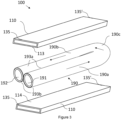
Figure 3 is an exploded view of the power cable assembly ofFigure 1 showing the busbars and a cooling tube, in an uncompressed state, having a U-shape according to embodiments of the present disclosure; -
Figures 4 provides an exploded view of an alternative power cable assembly providing two straight cooling tubes, showing in an uncompressed state, with the inlet and outlets provided at opposing ends of the power cable assembly according to embodiments of the present disclosure; -
Figure 5 is a block diagram showing an exemplary power distribution charging system using a power cable assembly ofFigures 1 to 3 according to embodiments of the present disclosure; and -
Figure 6 is a block diagram that illustrates the exemplary power distribution charging system ofFigure 5 using the power cable assembly ofFigure 4 according to embodiments of the present disclosure. - The following discussion provides many exemplary embodiments of the inventive subject matter. Although each embodiment represents a single combination of inventive elements, the inventive subject matter is considered to include all possible combinations of the disclosed elements. Thus, if one embodiment comprises elements A, B, and C, and a second embodiment comprises elements B and D, then the inventive subject matter is also considered to include other remaining combinations of A, B, C, or D, even if not explicitly disclosed.
- For simplicity and clarity of illustration, reference numerals may be repeated among the Figures to indicate corresponding or analogous elements. Numerous details are set forth to provide an understanding of the examples described herein. The examples may be practised without these details. In other instances, well-known methods, procedures, and components are not described in detail to avoid obscuring the examples described. The description is not to be considered as limited to the scope of the examples described herein.
-
Figures 1 to 3 show an exemplified implementation of apower cable assembly 100 having thecoolant inlet 191 andcoolant outlet 192 at the same end of thepower cable assembly 100 according to embodiments of the present disclosure. Having thecoolant inlet 191 andcoolant outlet 192 on the same end of thepower cable assembly 100 may reduce the form factor of thepower cable assembly 100 and the cost of manufacturing. - The
power cable assembly 100 comprises a first and a secondelectrical conductor 110, which may be in the form of insulated busbars, spaced apart from one another. Each of theinsulated busbars 100 comprise an electricallyconductive core 111 surrounded by an insulatinglayer 112. Thebusbars 110 are electrically conductive and extend longitudinally between a firstcontact end surface 135 and a secondend contact surface 135' at opposing ends of eachbusbar 110 and of thepower cable assembly 100. The contact surfaces 135 and 135' are conducting surfaces. For example, eachbusbar 110 may be coupled via first and second connectors to a node of an electrical connection, respectively. Eachbusbar 110 may be configured to carry a different voltage level. - A cooling
tube 190, also referred to as cooling pipe, is provided between the first andsecond busbars 110, such that opposingportions external surface 193 of a thermally conductingwall 197 of thecooling tube 190 are provided in direct contact withcorresponding portions layer 112 of theinsulated busbar 110 over a heat exchange region. As a result, heat generated at theconductive core 111 of eachinsulated busbar 110 is transferred over the heat exchange region to the cooling medium circulating into aninterior channel 196 defined by the thermallyconductive wall 197 of thecooling pipe 190 between acoolant inlet 191 and acoolant outlet 192. Thecoolant medium 125 is provided by acooling system 300 arranged in fluid communication with the coolingtube 190. Thecoolant medium 125 may be a water-based coolant such as a water and glycol mixture. Equally, thecoolant medium 125 may be a dielectric coolant such as purified water, oil-based coolant, or the like. - As shown in
figure 3 , the coolingtube 190 is U-shaped, thereby providing afirst segment 190a configured for directing thecoolant medium 125 along a forward flow path, and thesecond segment 190b provided parallel to thefirst segment 190a defining a return path for thecoolant medium 125 to theoutlet 192. Thefirst segment 190a and thesecond segment 190b are connected to one another via acurved segment 190c. In general, the coolingtube 190 is configured to extend along the length of thebusbars 110 to ensure maximum heat dissipation. In the arrangement shown inFigures 1 to 3 , each segment of thecooling tube 190 may be made from a flexible polymer material, such as synthetic rubber, having awall 197 thickness between 0.5 mm and 2.0 mm. - The sandwiched arrangement of the
busbar 110 and thecooling tube 190 may be collectively referred to as thepower cable core 170. - To further improve heat dissipation between the first and
second busbars 110, thebusbars 110 and thecooling tube 190 may be optionally embedded in a thermal interface material, TIM, 180. TheTIM 180 is configured to thermally couple theinsulated busbars 110 with the coolingtube 190, thereby extending the heat exchange region defined between theinsulated busbars 110 and thecooling tube 190. The use ofTIM 180 ensures that the entire external surface of thecooling tube 190 is thermally coupled to thebusbars 110. As such, portions 193c, 193d of theexternal surface 193, which are not in direct contact with the coolingtube 190, can be used to absorb heat from thebusbars 110. Therefore, the use ofTIM 180 further improves heat dissipation from thebusbar 110 to the cooling medium circulating in theinterior channel 196 of thecooling tube 190. TheTIM 180 may be a suitable material for efficiently transferring heat between surfaces. For example, theTIM 180 may be provided as a paste, a liquid, a film or sheet, and the like. TheTIM 180 may be any one of, but not limited to, a potting material, a grease material, a paste material, a semi-solid material, or a phase-change material. TheTIM 180, once applied, may be cured so as to encapsulate thebusbars 110 and thecooling tube 190. In this arrangement, theTIM 180 is part of thepower cable core 170 previously described. - As shown in
figures 1 and 2 , an insulatingmaterial 140, also referred to as an insulated jacket, is provided around thepower cable core 170. Theinsulated jacket 140 may be arranged to compress thepower cable core 170 to prevent relative movement of thebusbars 110 andcooling tube 190. The compressive force applied by theinsulation material 140 causes theflexible cooling tube 140 to elastically deform, as shown inFigure 2 . For example, in the uncompressed state, the coolingtube 190 may have a cylindrical or oval shape, as shown inFigure 3 . However, when compressed, the coolingtube 190 may have a rectangular shape, as shown inFigure 2 . The elastic deformation of thecooling tube 190 extends the available contact surface of the thermallyconductive wall 197 that is provided in direct contact with thebusbars 110, thereby improving heat dissipation. -
Figure 4 shows an alternative arrangement for apower cable assembly 200 with twostraight cooling tubes 290 rather than aU-shaped cooling tube 190, shown inFigures 1 to 3 . In this configuration, thecoolant inlet 291 andcoolant outlets 292 are provided on opposite ends of thepower cable assembly 200. - In the exemplary arrangements of
Figures 1 to 4 , thepower cable assembly 100 has a generally cylindrical form. As illustrated, thebusbars 110 have a generally rectangular cross-sectional profile. As previously discussed, the coolingtube cooling tube busbars 110 and/or thecooling tube 190 may, for example, have an oval or circular form in cross-section. -
Figure 5 shows an exemplified implementation of apower distribution system 500 of a vehicle incorporating thepower cable assembly 100 ofFigures 1 to 3 . The exemplarypower distribution system 500 comprises thepower cable assembly 100 and anintegrated cooling system 300. Thepower cable assembly 100 is coupled to thecooling system 300 via corresponding connectors provided at theinlet 191 andoutlet 192 points of thepower cable assembly 100. Thecooling system 300 provides a closed-loop coolant circulation system when the cooling medium is circulated by means of apump 320 from thecoolant outlet 192 ofinterior channel 196 of thecooling tube 190 to acooling unit 330, where the heat from thecoolant medium 125 is extracted, and thecoolant medium 125 is fed back to theinterior channel 196 via thecoolant inlet 191. - The
power distribution system 500 may be configured for transmitted electrical power, via apower cable assembly 100, between a firstelectrical connection 510 and a secondelectrical connection 520 of a vehicle. - In the exemplary arrangement of
Figure 5 , the coolant inlet 301 and coolant outlet 302 are located on the same side of thepower cable assembly 100. -
Figure 6 shows the exemplifiedpower distribution system 500 offigure 5 incorporating thepower cable assembly 200 ofFigure 4 , whereby theinlet 291 andoutlet 292 are positioned on opposing ends of thepower cable assembly 100. Thepower distribution 500figure 6 operates in the same way as the one presented with reference toFigure 5 , but in this arrangement, thecoolant inlet 291 andcoolant outlets 292 are positioned on opposing ends of thepower cable assembly 200. - While the
charging system 500 andpower cable assembly
Claims (15)
- A power cable assembly (100) comprising:a power cable core (170) comprising:first and second electrical conductors (110) spaced apart from one another and extending longitudinally, each electrical conductor (110) comprising an electrically conductive core (111) surrounded by an insulating material (112), anda longitudinally extending cooling tube (190) comprising a thermally conductive wall (197) defining an interior channel (196) for circulating, between a coolant inlet (191) and a coolant outlet (192) of the cooling tube (190), a coolant medium (125); andan insulating layer (140) surrounding the power cable core (170);wherein the cooling tube (190) is arranged between the first and second electrical conductors (110) such that opposing portions (193a, 193b) of an external surface (193) of the thermally conductive wall (197) are provided in direct contact with corresponding portions (113, 114) of the insulating material (112) of the electrical conductors (110) over a heat exchange region so as to transfer heat from the electrically conductive core (111) of the electrical conductors (110) to the coolant medium (125) circulating in the interior channel (196) of the cooling tube (190).
- The power cable assembly (100) of claim 1, wherein the cooling tube (190) comprises a first tube segment (190a) defining a forward flow path for the coolant medium (125), and a second tube segment (190b) extending parallel to the first tube segment (190a) and defining a return flow path for the coolant medium (125) between the coolant inlet (191) and coolant outlet (192), the first tube segment (190a) and second tube segment (190b) being connected via a curved segment (190c).
- The power cable assembly (100) of claim 2, wherein the coolant inlet (191) and the coolant outlet (192) of the cooling tube (190) are arranged at the same end of the power cable assembly (100).
- The power cable assembly (100) of any one of the preceding claims, wherein the cooling tube (190) has a U shape.
- The power cable assembly (100) of any one of the preceding claims, wherein the power cable core (170) comprises a single cooling tube (190).
- The power cable assembly (100) of claim 1, wherein the power cable core (170) comprises one or more straight cooling tubes (290) extending between a coolant inlet (291) and a coolant outlet (292) provided at opposite ends of the power cable assembly (100).
- The power cable assembly (100) of any one of the preceding claims, wherein the cooling tube (190) is made from a flexible polymer material.
- The power cable assembly (100) of claim 7, wherein the thickness of the thermally conductive wall (197) of the cooling tube (190) is between 0.5 mm and 2.0 mm.
- The power cable assembly (100) of any one of the preceding claims, wherein the insulating layer (140) is arranged to apply a compressive force on the power cable core (170) causing the thermally conductive wall (197) of the cooling tube (190) to elastically deform so as to extend the heat transfer region between the cooling tube (190) and electrical conductors (110).
- The power cable assembly (100) of any one of the preceding claims, wherein the power cable core (170) comprises a thermal interface material, TIM, (180) surrounding the cooling tube (190) and the electrical conductors (110), the TIM (180) being configured to thermally couple the external surface (197) of the cooling tube (190) to the electrical conductor (110) such that the heat generated at the electrically conductive core (111) is transferred to the coolant medium (125).
- The power cable assembly (100) of claim 10, wherein the thermal interface material, TIM, (180) comprises any one of: a potting material, a grease material, a paste material, a semi-solid material; or a phase-change material.
- The power cable assembly (100) of any one of the preceding claims, wherein the electrical conductors (110) are in the form of busbars having a rectangular cross-sectional profile.
- The power cable assembly (100) of any one of the preceding claims, wherein each electrical conductor (110) is arranged to carry a different voltage level.
- A cooling system (300) configured for coupling to a power cable assembly according to any one of claims 1 to 13 for circulating a cooling medium (125) between the coolant inlet (191) and coolant outlet (192) of the interior channel (196) of the cooling tube (190), the cooling system (300) comprising:a pump (320),a cooling unit (330); andone or more connectors for connecting the coolant inlet (191) and coolant outlet (192) to the cooling system (300),wherein the coolant medium (125) is circulated, via the cooling unit (330), through the interior channel (196) of the cooling tube (190) between the coolant inlet (191) and the coolant outlet (192).
- A power distribution system (500) of a vehicle comprising:
a power cable assembly (100) according to any one of claims 1 to 13 extending between first and second end contact surfaces (135, 135') configured for coupling, via first and second connectors, to respective electrical connections (510, 520) of the power distribution system (500); and an integrated cooling system (300) according to claim 14 coupled to the power cable assembly (100) for circulating the cooling medium (125) between the coolant inlet (191) and coolant outlet (192) of the interior channel (196) of the cooling tube (190).
Priority Applications (3)
| Application Number | Priority Date | Filing Date | Title |
|---|---|---|---|
| EP21188670.0A EP4125098A1 (en) | 2021-07-30 | 2021-07-30 | A power cable assembly for a power distribution system having an integrated cooling system |
| US17/876,299 US11935672B2 (en) | 2021-07-30 | 2022-07-28 | Power cable assembly for a power distribution system having an integrated cooling system |
| CN202210904483.2A CN115691891A (en) | 2021-07-30 | 2022-07-29 | Cable assemblies for power distribution systems with integrated cooling systems |
Applications Claiming Priority (1)
| Application Number | Priority Date | Filing Date | Title |
|---|---|---|---|
| EP21188670.0A EP4125098A1 (en) | 2021-07-30 | 2021-07-30 | A power cable assembly for a power distribution system having an integrated cooling system |
Publications (1)
| Publication Number | Publication Date |
|---|---|
| EP4125098A1 true EP4125098A1 (en) | 2023-02-01 |
Family
ID=77167980
Family Applications (1)
| Application Number | Title | Priority Date | Filing Date |
|---|---|---|---|
| EP21188670.0A Pending EP4125098A1 (en) | 2021-07-30 | 2021-07-30 | A power cable assembly for a power distribution system having an integrated cooling system |
Country Status (3)
| Country | Link |
|---|---|
| US (1) | US11935672B2 (en) |
| EP (1) | EP4125098A1 (en) |
| CN (1) | CN115691891A (en) |
Cited By (1)
| Publication number | Priority date | Publication date | Assignee | Title |
|---|---|---|---|---|
| CN117476284A (en) * | 2023-12-26 | 2024-01-30 | 博西源线缆有限公司 | New energy safety type high-voltage cable |
Families Citing this family (9)
| Publication number | Priority date | Publication date | Assignee | Title |
|---|---|---|---|---|
| FR3117662B1 (en) * | 2020-12-14 | 2023-03-03 | Valeo Systemes Thermiques | Cooling element for an electrical charging cable of an electrical energy storage device and corresponding method of installation. |
| US11987142B2 (en) * | 2021-03-26 | 2024-05-21 | Toyota Motor Engineering & Manufacturing North America, Inc. | Temperature regulation of vehicle charging components |
| EP4480737B1 (en) * | 2023-06-22 | 2026-04-15 | ABB E-mobility B.V. | Dc charging cable assembly for charging an electrical vehicle, dc charging system for charging an electrical vehicle and method for charging an electrical vehicle |
| DE102023118247A1 (en) * | 2023-07-11 | 2025-01-16 | Preh Gmbh | Busbar and charging element comprising a busbar |
| WO2025218786A1 (en) * | 2024-04-19 | 2025-10-23 | Amphenol Pcd (Shenzhen) Co., Ltd. | Liquid-cooled cable and system thereof |
| EP4644165A1 (en) * | 2024-05-02 | 2025-11-05 | Aptiv Technologies AG | Charging cable cooled with an automotive climate system |
| CN118418797B (en) * | 2024-07-05 | 2024-08-23 | 深圳市鸿嘉利新能源有限公司 | Multi-runner efficient heat exchange type liquid cooling super-charging new energy charging station |
| CN121282645A (en) * | 2024-07-05 | 2026-01-06 | 泰科电子(上海)有限公司 | Electric transmission member, electric transmission assembly, electric connection assembly, and electric connection device |
| CN121282644A (en) * | 2024-07-05 | 2026-01-06 | 泰科电子(上海)有限公司 | Electric transmission member, electric transmission assembly, electric connection assembly, and electric connection device |
Citations (10)
| Publication number | Priority date | Publication date | Assignee | Title |
|---|---|---|---|---|
| EP2652754A1 (en) * | 2010-12-15 | 2013-10-23 | ABB Technology AG | High voltage electric cable |
| US20170320454A1 (en) * | 2015-01-28 | 2017-11-09 | Bayerische Motoren Werke Aktiengesellschaft | Supply Rail for a Motor Vehicle |
| WO2018060151A1 (en) | 2016-09-27 | 2018-04-05 | Phoenix Contact E-Mobility Gmbh | Charging system for charging an electric vehicle |
| US20180190410A1 (en) * | 2016-09-30 | 2018-07-05 | Faraday&Future Inc. | Liquid-cooled tangle resistant charge cable |
| US20180277283A1 (en) * | 2017-03-21 | 2018-09-27 | Dr. Ing. H.C. F. Porsche Aktiengesellschaft | Charging cable assembly |
| US20190131035A1 (en) * | 2016-04-14 | 2019-05-02 | Phoenix Contact E-Mobility Gmbh | Charging Cable For Transmitting Electrical Energy, Charging Plug and Charging Station For Discharging Electrical Energy To a Recipient of Electrical Energy |
| KR102120306B1 (en) | 2019-10-04 | 2020-06-08 | 대영채비(주) | Fast-charging cable for electric vehicles |
| US20200343022A1 (en) * | 2019-04-25 | 2020-10-29 | Hanon Systems | Electric vehicle onboard charging cable cooling |
| EP3734618A1 (en) * | 2019-05-01 | 2020-11-04 | Prysmian S.p.A. | Charging system for an electric energy storage |
| US20200391601A1 (en) * | 2019-06-14 | 2020-12-17 | Honda Motor Co., Ltd. | Electric vehicle cooling system |
Family Cites Families (104)
| Publication number | Priority date | Publication date | Assignee | Title |
|---|---|---|---|---|
| US1539490A (en) * | 1922-12-13 | 1925-05-26 | Hunter Philip Vassar | Manufacture of electric cables |
| DE8427918U1 (en) | 1984-09-22 | 1984-12-13 | Dr.Ing.H.C. F. Porsche Ag, 7000 Stuttgart | SUPPLY AIR CHANNEL FOR A INTERCOOLER |
| DE3627149A1 (en) | 1986-08-11 | 1988-02-18 | Felten & Guilleaume Energie | Cable system for transmitting high powers through high-voltage cables with an externally located coolant drive |
| DE4209928C1 (en) | 1992-03-24 | 1992-12-24 | Felten & Guilleaume Energietechnik Ag, 5000 Koeln, De | |
| GB9210572D0 (en) | 1992-05-18 | 1992-07-01 | Ca Nat Research Council | High voltage insulation |
| US5670860A (en) | 1995-06-06 | 1997-09-23 | Hughes Electronics | High power, high frequency, liquid-cooled transmission cable and charging system |
| EP0824285B1 (en) | 1996-08-14 | 2000-03-29 | Felten & Guilleaume AG | Method for operating a cable installation |
| DE10008807A1 (en) | 2000-02-25 | 2001-09-06 | Siemens Ag | Rotary electric machine and method for cooling an electric rotary machine |
| JPWO2007032391A1 (en) * | 2005-09-13 | 2009-03-19 | 株式会社オートネットワーク技術研究所 | Conductor for vehicle |
| KR20090103405A (en) | 2008-03-28 | 2009-10-01 | 캄텍주식회사 | EGR cooler for automobile |
| FR2935475B1 (en) | 2008-08-27 | 2012-12-07 | Valeo Systemes Thermiques | HEAT EXCHANGER FOR COOLING A FLUID, ESPECIALLY RECIRCULATED EXHAUST GASES OF A HEAT ENGINE |
| DE102011014908A1 (en) | 2011-03-24 | 2011-11-10 | Daimler Ag | Tail pipe arrangement for exhaust system of vehicle, comprises inlet, by which surrounding air is introduced into exhaust flow for cooling exhaust flow |
| EP2637179B1 (en) | 2012-03-05 | 2015-02-18 | Antrova AG | Self-cooling coaxial high voltage cable and method for operating same |
| CN203450055U (en) | 2013-08-19 | 2014-02-26 | 广州汽车集团股份有限公司 | Vehicle high-voltage wire harness and cooling water pipe through hole device and vehicle |
| US9321362B2 (en) | 2014-02-05 | 2016-04-26 | Tesia Motors, Inc. | Cooling of charging cable |
| CN203858902U (en) * | 2014-05-19 | 2014-10-01 | 广东威恒输变电工程有限公司 | Cooling cable |
| DE102015100347A1 (en) | 2015-01-12 | 2016-07-14 | Phoenix Contact E-Mobility Gmbh | Electrical connection body for a charging plug and / or a charging socket, charging plug and charging station for delivering electrical energy to a receiver of electrical energy |
| DE102015119338B4 (en) | 2015-11-10 | 2018-01-25 | Phoenix Contact E-Mobility Gmbh | Contact assembly and connector part e.g. for a charging plug |
| DE102016204894A1 (en) | 2016-03-23 | 2017-09-28 | Phoenix Contact E-Mobility Gmbh | Charging plug and charging station for delivering electrical energy to a receiver of electrical energy |
| DE102016204895B4 (en) | 2016-03-23 | 2020-11-12 | Phoenix Contact E-Mobility Gmbh | Charging connector with a power contact system and charging station for delivering electrical energy to a receiver of electrical energy |
| FR3050192B1 (en) | 2016-04-18 | 2019-05-03 | Renault S.A.S | PORTABLE DEVICE FOR THE DEVIDING OF AN ELECTRIC CABLE, IN PARTICULAR A LOAD CABLE FOR AN ELECTRIC OR HYBRID VEHICLE |
| CA3250062A1 (en) * | 2016-05-20 | 2025-06-17 | Southwire Company, Llc | Liquid cooled charging cable system |
| DE102016117261B3 (en) | 2016-09-14 | 2017-11-30 | HARTING Automotive GmbH | System consisting of a connector, a fluid-cooled cable and a connection unit |
| CN106849227A (en) | 2017-01-13 | 2017-06-13 | 深圳市沃尔核材股份有限公司 | Charging equipment cooling system |
| CN106849238B (en) | 2017-02-17 | 2024-04-26 | 深圳市沃尔新能源电气科技股份有限公司 | Charging equipment cooling system |
| CN106849228A (en) | 2017-01-13 | 2017-06-13 | 深圳市沃尔核材股份有限公司 | Charging equipment cooling system |
| CN206314142U (en) | 2016-11-29 | 2017-07-07 | 深圳市五洲龙汽车股份有限公司 | A kind of charging electric vehicle socket and its heat abstractor |
| CN106782835B (en) | 2016-12-20 | 2019-07-16 | 深圳宝兴电线电缆制造有限公司 | Electric car large current charge cable |
| CN206697276U (en) | 2016-12-20 | 2017-12-01 | 深圳宝兴电线电缆制造有限公司 | A kind of electric automobile large current charge cable |
| DE102017103271A1 (en) | 2017-02-17 | 2018-08-23 | Benteler Automobiltechnik Gmbh | Electrical charging arrangement and motor vehicle |
| CN207082683U (en) | 2017-03-13 | 2018-03-09 | 深圳市沃尔核材股份有限公司 | charging socket with automatic cooling function |
| US11034253B2 (en) | 2017-04-24 | 2021-06-15 | Chargepoint, Inc. | Liquid cooled charging cable for charging electric vehicles |
| DE202017102535U1 (en) | 2017-04-28 | 2018-05-03 | Hradil Spezialkabel Gmbh | Charging cable for electric vehicles |
| CN206741986U (en) | 2017-04-28 | 2017-12-12 | 深圳宝兴电线电缆制造有限公司 | Electric automobile cools down charging cable |
| CN206864231U (en) | 2017-05-24 | 2018-01-09 | 深圳宝兴电线电缆制造有限公司 | A kind of electric automobile cools down charging cable |
| CN107082030B (en) | 2017-05-24 | 2023-07-07 | 深圳市沃尔核材股份有限公司 | Charging equipment cooling system |
| CN107425323B (en) | 2017-08-28 | 2022-07-05 | 深圳市沃尔新能源电气科技股份有限公司 | Female terminal of pegging graft and applied rifle, the rifle socket that charges of this female terminal |
| CN107640046B (en) | 2017-09-13 | 2020-10-09 | 常州大学 | A charging pile with cable cooling |
| CN110014954B (en) | 2017-09-30 | 2021-05-14 | 比亚迪股份有限公司 | Charging connecting piece |
| CN207931502U (en) | 2017-09-30 | 2018-10-02 | 比亚迪股份有限公司 | Charging connector and vehicle and charging system |
| CN207374157U (en) | 2017-10-31 | 2018-05-18 | 宁德时代新能源科技股份有限公司 | Charging unit |
| CN107933340A (en) | 2017-11-06 | 2018-04-20 | 深圳市沃尔新能源电气科技股份有限公司 | The cold high power charging device of liquid and its monitoring method |
| CN108199162B (en) | 2017-12-22 | 2024-01-26 | 深圳市沃尔新能源电气科技股份有限公司 | Liquid cooling charging socket |
| US11660970B2 (en) | 2018-01-05 | 2023-05-30 | Byton Limited | On-board liquid-cooled or gas-cooled charging cable for electric vehicles |
| CN110098011A (en) | 2018-01-30 | 2019-08-06 | 广州南洋电缆有限公司 | Cable is used in a kind of charging of new-energy automobile |
| DE102018102207A1 (en) | 2018-02-01 | 2019-08-01 | Dr. Ing. H.C. F. Porsche Aktiengesellschaft | Vehicle charging cable |
| CN208189243U (en) | 2018-02-09 | 2018-12-04 | 江苏艾立可电子科技有限公司 | A kind of ventilation type New-energy electric vehicle charging pile cable |
| CN208093243U (en) | 2018-02-09 | 2018-11-13 | 江苏艾立可电子科技有限公司 | A kind of liquid cooling charging-self type New-energy electric vehicle charging pile cable |
| CN208111849U (en) | 2018-03-08 | 2018-11-16 | 浙江零跑科技有限公司 | A kind of arrangements of electric connection for the high-power charging of electric car |
| WO2019184882A1 (en) | 2018-03-26 | 2019-10-03 | 洛阳正奇机械有限公司 | Parallel cold liquid-cooled cable for exclusive use of high-power charging pile positive pole and negative pole |
| CN108461188A (en) | 2018-03-26 | 2018-08-28 | 洛阳正奇机械有限公司 | A kind of special liquid cooling cable DC+ of high-power charging pile and DC- and cold software conducting wire |
| CN208263991U (en) | 2018-03-29 | 2018-12-21 | 山丹县尚丰节能服务有限责任公司 | It is a kind of full of the electric car charger autotomyed |
| JP7035738B2 (en) | 2018-04-06 | 2022-03-15 | トヨタ自動車株式会社 | Vehicles and how to charge the vehicle |
| CN108597654A (en) | 2018-04-20 | 2018-09-28 | 安徽知之信息科技有限公司 | A kind of new-energy automobile charging cable |
| CN108377633A (en) | 2018-04-24 | 2018-08-07 | 上海上汽安悦充电科技有限公司 | A kind of charging gun with cooling line |
| CN108372794A (en) | 2018-04-24 | 2018-08-07 | 上海上汽安悦充电科技有限公司 | A kind of charging gun with cooling line switching device |
| EP3572271B1 (en) | 2018-05-24 | 2023-07-05 | ABB E-mobility B.V. | Electrical vehicle charging system for charging an electrical vehicle |
| CN108461952A (en) | 2018-06-06 | 2018-08-28 | 洛阳正奇机械有限公司 | A kind of special DC+ of direct current 600A charging guns is bent liquid cooling terminal with the tail portions DC- |
| CN208539163U (en) | 2018-06-06 | 2019-02-22 | 洛阳正奇机械有限公司 | A kind of dedicated DC+ of direct current 600A charging gun and the tail portion DC- are bent liquid cooling terminal |
| DE102018113450A1 (en) | 2018-06-06 | 2019-12-12 | Dr. Ing. H.C. F. Porsche Aktiengesellschaft | A method of charging a traction battery of a motor vehicle |
| ES2865388T3 (en) | 2018-06-27 | 2021-10-15 | Abb Schweiz Ag | Electric Vehicle Charging Equipment |
| CN108878014A (en) | 2018-07-27 | 2018-11-23 | 中天科技装备电缆有限公司 | A kind of cooling type high temperature resistant direct current charging cable |
| CN208460422U (en) | 2018-07-27 | 2019-02-01 | 中天科技装备电缆有限公司 | A kind of cooling type high temperature resistant direct current charging cable |
| CN108922658A (en) | 2018-08-03 | 2018-11-30 | 威海市泓淋电力技术股份有限公司 | A kind of high-power charging gun cable with refrigerating function |
| CN208706298U (en) | 2018-08-07 | 2019-04-05 | 远东电缆有限公司 | A kind of new-energy automobile high-speed high-power charging tensile flexible cable |
| CN208538552U (en) | 2018-08-07 | 2019-02-22 | 广东天虹电缆有限公司 | A kind of direct current charge cable cooled down automatically |
| CN109148015A (en) | 2018-08-07 | 2019-01-04 | 远东电缆有限公司 | A kind of new-energy automobile high-speed high-power charging tensile flexible cable and its production technology |
| CN208753040U (en) | 2018-09-06 | 2019-04-16 | 宁波聚亿新能源科技有限公司 | A kind of liquid cooling cable and the electric vehicle charging cables cooling device using it |
| CN109215872A (en) | 2018-09-06 | 2019-01-15 | 宁波聚亿新能源科技有限公司 | A kind of liquid cooling cable and the electric vehicle charging cables cooling device using it |
| CN109323496A (en) | 2018-09-10 | 2019-02-12 | 成都深冷液化设备股份有限公司 | Using liquid nitrogen or liquid air as the charging cable gas circulating cooling method of cold source |
| KR20200030929A (en) | 2018-09-13 | 2020-03-23 | (주)클린일렉스 | Rapid charging apparatus for electric car |
| EP3624141B1 (en) | 2018-09-14 | 2023-11-01 | BRUGG eConnect AG | Coolable individual line and charging cable |
| DE102018122680B3 (en) | 2018-09-17 | 2020-02-20 | Dr. Ing. H.C. F. Porsche Aktiengesellschaft | Vehicle charging cable |
| CN209489044U (en) | 2018-09-26 | 2019-10-11 | 比亚迪股份有限公司 | charging device |
| CH715611B1 (en) | 2018-12-05 | 2022-05-13 | BRUGG eConnect AG | Connection element for the electrical connection of a fluid-coolable individual line, fluid-coolable individual line unit and charging cable. |
| CN109788713B (en) | 2019-01-17 | 2020-03-10 | 深圳市宝道智能科技有限公司 | Fluid cooling charging device |
| CN109935415A (en) | 2019-02-25 | 2019-06-25 | 顺科新能源技术股份有限公司 | A portable charging gun structure with cooling function |
| CN109969022A (en) | 2019-03-27 | 2019-07-05 | 成都宇坤健元新能源科技有限公司 | A kind of high-power charging pile of energy conservation and environmental protection and its cooling means |
| CN209747218U (en) | 2019-04-02 | 2019-12-06 | 上海起帆电缆股份有限公司 | A high current-carrying fast charging cable |
| JP2020182298A (en) | 2019-04-24 | 2020-11-05 | 三菱自動車工業株式会社 | Charging cable with hoisting device |
| DE102019112843B3 (en) | 2019-05-16 | 2020-09-03 | Dr. Ing. H.C. F. Porsche Aktiengesellschaft | Automotive charging cables |
| DE102019114765B3 (en) | 2019-06-03 | 2020-10-15 | Dr. Ing. H.C. F. Porsche Aktiengesellschaft | Charging cable arrangement for charging a traction battery of an electric vehicle |
| CN110136877B (en) | 2019-06-18 | 2024-05-14 | 远东电缆有限公司 | Cable for liquid-cooled high-power charging pile and production process thereof |
| CN209804304U (en) | 2019-06-18 | 2019-12-17 | 远东电缆有限公司 | Liquid cooling high-power cable for charging pile |
| CN209912570U (en) | 2019-07-03 | 2020-01-07 | 无锡鑫宏业特塑线缆有限公司 | High-temperature-resistant charging pile cable for automobile |
| CN209962721U (en) | 2019-07-08 | 2020-01-17 | 江苏宝建特种电缆有限公司 | Cable for automobile charging |
| CN110416777B (en) | 2019-07-23 | 2024-11-26 | 深圳巴斯巴科技发展有限公司 | Liquid-cooled charging connector and assembly method thereof |
| CN210805262U (en) | 2019-07-23 | 2020-06-19 | 上海起帆电缆股份有限公司 | A high-current-carrying fast charging cable |
| EP3770925B1 (en) * | 2019-07-25 | 2023-12-27 | ABB E-mobility B.V. | Heavy-current charging cable for charging an electric vehicle |
| CN210516261U (en) | 2019-08-20 | 2020-05-12 | 深圳巴斯巴科技发展有限公司 | High-power charging liquid cooling cable |
| CN210640035U (en) | 2019-09-06 | 2020-05-29 | 何华山 | Large-current charging cable |
| CN210295942U (en) | 2019-09-10 | 2020-04-10 | 远东电缆有限公司 | High-power charging pile cable |
| CN111048247A (en) | 2019-12-14 | 2020-04-21 | 安徽太平洋电缆股份有限公司 | Charging pile cable |
| CN211641866U (en) | 2019-12-18 | 2020-10-09 | 重庆国翰能源发展有限公司 | High-power rifle that charges that fills electric pile with liquid cooling structure |
| CN111016707B (en) | 2020-01-06 | 2024-04-12 | 四川永贵科技有限公司 | Liquid cooling heavy current charging system of electric automobile and control method thereof |
| CN211592278U (en) | 2020-01-06 | 2020-09-29 | 四川永贵科技有限公司 | Liquid cooling large current charging system of electric automobile |
| CN211605534U (en) | 2020-01-20 | 2020-09-29 | 洛阳正奇机械有限公司 | Liquid cooling conductive jack for liquid cooling charging socket of new energy electric automobile |
| CN211294720U (en) | 2020-01-20 | 2020-08-18 | 洛阳正奇机械有限公司 | Liquid cooling cable body for liquid cooling charging socket of new energy electric automobile |
| CN211295493U (en) | 2020-01-20 | 2020-08-18 | 洛阳正奇机械有限公司 | Taper hole electrode of liquid cooling cable for liquid cooling charging socket of new energy electric automobile |
| CN111106488A (en) | 2020-01-20 | 2020-05-05 | 洛阳正奇机械有限公司 | A liquid-cooled conductive jack for a liquid-cooled charging socket for a new energy electric vehicle |
| CN111200200B (en) | 2020-01-20 | 2021-02-09 | 洛阳正奇机械有限公司 | Liquid cooling cable for liquid cooling charging socket of new energy electric automobile |
| CN211237803U (en) | 2020-02-26 | 2020-08-11 | 贵州安培尔电力科技有限公司 | Energy saving oil injection cooling cable |
| CN212073704U (en) | 2020-03-06 | 2020-12-04 | 重庆国翰能源发展有限公司 | Rifle line cooling device charges |
| CN211479709U (en) | 2020-03-20 | 2020-09-11 | 江苏联通智能控制技术股份有限公司 | Oil cooling high-power charging special cable |
-
2021
- 2021-07-30 EP EP21188670.0A patent/EP4125098A1/en active Pending
-
2022
- 2022-07-28 US US17/876,299 patent/US11935672B2/en active Active
- 2022-07-29 CN CN202210904483.2A patent/CN115691891A/en active Pending
Patent Citations (10)
| Publication number | Priority date | Publication date | Assignee | Title |
|---|---|---|---|---|
| EP2652754A1 (en) * | 2010-12-15 | 2013-10-23 | ABB Technology AG | High voltage electric cable |
| US20170320454A1 (en) * | 2015-01-28 | 2017-11-09 | Bayerische Motoren Werke Aktiengesellschaft | Supply Rail for a Motor Vehicle |
| US20190131035A1 (en) * | 2016-04-14 | 2019-05-02 | Phoenix Contact E-Mobility Gmbh | Charging Cable For Transmitting Electrical Energy, Charging Plug and Charging Station For Discharging Electrical Energy To a Recipient of Electrical Energy |
| WO2018060151A1 (en) | 2016-09-27 | 2018-04-05 | Phoenix Contact E-Mobility Gmbh | Charging system for charging an electric vehicle |
| US20180190410A1 (en) * | 2016-09-30 | 2018-07-05 | Faraday&Future Inc. | Liquid-cooled tangle resistant charge cable |
| US20180277283A1 (en) * | 2017-03-21 | 2018-09-27 | Dr. Ing. H.C. F. Porsche Aktiengesellschaft | Charging cable assembly |
| US20200343022A1 (en) * | 2019-04-25 | 2020-10-29 | Hanon Systems | Electric vehicle onboard charging cable cooling |
| EP3734618A1 (en) * | 2019-05-01 | 2020-11-04 | Prysmian S.p.A. | Charging system for an electric energy storage |
| US20200391601A1 (en) * | 2019-06-14 | 2020-12-17 | Honda Motor Co., Ltd. | Electric vehicle cooling system |
| KR102120306B1 (en) | 2019-10-04 | 2020-06-08 | 대영채비(주) | Fast-charging cable for electric vehicles |
Cited By (2)
| Publication number | Priority date | Publication date | Assignee | Title |
|---|---|---|---|---|
| CN117476284A (en) * | 2023-12-26 | 2024-01-30 | 博西源线缆有限公司 | New energy safety type high-voltage cable |
| CN117476284B (en) * | 2023-12-26 | 2024-03-08 | 博西源线缆有限公司 | New energy safety type high-voltage cable |
Also Published As
| Publication number | Publication date |
|---|---|
| CN115691891A (en) | 2023-02-03 |
| US20230035457A1 (en) | 2023-02-02 |
| US11935672B2 (en) | 2024-03-19 |
Similar Documents
| Publication | Publication Date | Title |
|---|---|---|
| EP4125098A1 (en) | A power cable assembly for a power distribution system having an integrated cooling system | |
| US12154706B2 (en) | Power cable assembly for a power distribution system having an integrated cooling system | |
| KR102667074B1 (en) | Charging cable assembly for electric vehicle | |
| US11433773B2 (en) | Charging harness unit for a battery of a motor vehicle | |
| CN115552695A (en) | Cooling system for a busbar | |
| EP3379655A1 (en) | Electrical connector and electrical connection arrangement comprising an electrical connector | |
| JP2010521796A5 (en) | ||
| KR20210055001A (en) | Charging cable assembly for electric vehicle | |
| US20230034451A1 (en) | Power cable assembly for a power distribution system having an integrated cooling system | |
| EP4113542A1 (en) | Power conductor and vehicle power distribution circuit incorporating the same | |
| US11923113B2 (en) | Power cable assembly for a power distribution system having an integrated cooling system | |
| US11590910B2 (en) | High-voltage line and high-voltage system | |
| CN115938672A (en) | Liquid Cooled Wiring Harnesses and Vehicles | |
| US12482960B2 (en) | Electrical connector for connecting high voltage power cable including electrical conductor to electrical terminal | |
| CN211088572U (en) | Cable terminal subassembly and vehicle that has it | |
| EP4099514A1 (en) | Cooled inlet cold plate design for robust electrical isolation | |
| CN117120294A (en) | Cooling device for cooling at least one wire connected to a plug-in connector part | |
| CN217182908U (en) | High-efficient heat dissipation low impedance intensive bus duct | |
| CN218471654U (en) | Liquid cooling cable and charging device | |
| EP4703185A1 (en) | Cooled charging conductor assembly with extended internal heat transfer surfaces | |
| JP7178858B2 (en) | Power connector with cable | |
| CN223877879U (en) | Cable, rifle and charging device charge | |
| CN220733032U (en) | Heater structure and heating system with same | |
| CN114822967B (en) | Liquid cooling cable and charging device | |
| CN223890832U (en) | Charging gun, heat dissipation assembly and charging pile |
Legal Events
| Date | Code | Title | Description |
|---|---|---|---|
| PUAI | Public reference made under article 153(3) epc to a published international application that has entered the european phase |
Free format text: ORIGINAL CODE: 0009012 |
|
| STAA | Information on the status of an ep patent application or granted ep patent |
Free format text: STATUS: THE APPLICATION HAS BEEN PUBLISHED |
|
| AK | Designated contracting states |
Kind code of ref document: A1 Designated state(s): AL AT BE BG CH CY CZ DE DK EE ES FI FR GB GR HR HU IE IS IT LI LT LU LV MC MK MT NL NO PL PT RO RS SE SI SK SM TR |
|
| RAP3 | Party data changed (applicant data changed or rights of an application transferred) |
Owner name: APTIV TECHNOLOGIES LIMITED |
|
| STAA | Information on the status of an ep patent application or granted ep patent |
Free format text: STATUS: REQUEST FOR EXAMINATION WAS MADE |
|
| 17P | Request for examination filed |
Effective date: 20230731 |
|
| RBV | Designated contracting states (corrected) |
Designated state(s): AL AT BE BG CH CY CZ DE DK EE ES FI FR GB GR HR HU IE IS IT LI LT LU LV MC MK MT NL NO PL PT RO RS SE SI SK SM TR |
|
| STAA | Information on the status of an ep patent application or granted ep patent |
Free format text: STATUS: EXAMINATION IS IN PROGRESS |
|
| 17Q | First examination report despatched |
Effective date: 20240719 |
|
| RAP1 | Party data changed (applicant data changed or rights of an application transferred) |
Owner name: APTIV TECHNOLOGIES AG |