EP4124914A1 - Image forming apparatus - Google Patents
Image forming apparatus Download PDFInfo
- Publication number
- EP4124914A1 EP4124914A1 EP22185799.8A EP22185799A EP4124914A1 EP 4124914 A1 EP4124914 A1 EP 4124914A1 EP 22185799 A EP22185799 A EP 22185799A EP 4124914 A1 EP4124914 A1 EP 4124914A1
- Authority
- EP
- European Patent Office
- Prior art keywords
- drive
- sheet
- image forming
- drive roller
- forming apparatus
- Prior art date
- Legal status (The legal status is an assumption and is not a legal conclusion. Google has not performed a legal analysis and makes no representation as to the accuracy of the status listed.)
- Granted
Links
Images



Classifications
-
- G—PHYSICS
- G03—PHOTOGRAPHY; CINEMATOGRAPHY; ANALOGOUS TECHNIQUES USING WAVES OTHER THAN OPTICAL WAVES; ELECTROGRAPHY; HOLOGRAPHY
- G03G—ELECTROGRAPHY; ELECTROPHOTOGRAPHY; MAGNETOGRAPHY
- G03G15/00—Apparatus for electrographic processes using a charge pattern
- G03G15/22—Apparatus for electrographic processes using a charge pattern involving the combination of more than one step according to groups G03G13/02 - G03G13/20
- G03G15/23—Apparatus for electrographic processes using a charge pattern involving the combination of more than one step according to groups G03G13/02 - G03G13/20 specially adapted for copying both sides of an original or for copying on both sides of a recording or image-receiving material
- G03G15/231—Arrangements for copying on both sides of a recording or image-receiving material
- G03G15/232—Arrangements for copying on both sides of a recording or image-receiving material using a single reusable electrographic recording member
- G03G15/234—Arrangements for copying on both sides of a recording or image-receiving material using a single reusable electrographic recording member by inverting and refeeding the image receiving material with an image on one face to the recording member to transfer a second image on its second face, e.g. by using a duplex tray; Details of duplex trays or inverters
-
- G—PHYSICS
- G03—PHOTOGRAPHY; CINEMATOGRAPHY; ANALOGOUS TECHNIQUES USING WAVES OTHER THAN OPTICAL WAVES; ELECTROGRAPHY; HOLOGRAPHY
- G03G—ELECTROGRAPHY; ELECTROPHOTOGRAPHY; MAGNETOGRAPHY
- G03G21/00—Arrangements not provided for by groups G03G13/00 - G03G19/00, e.g. cleaning, elimination of residual charge
- G03G21/16—Mechanical means for facilitating the maintenance of the apparatus, e.g. modular arrangements
- G03G21/1604—Arrangement or disposition of the entire apparatus
- G03G21/1623—Means to access the interior of the apparatus
- G03G21/1633—Means to access the interior of the apparatus using doors or covers
-
- G—PHYSICS
- G03—PHOTOGRAPHY; CINEMATOGRAPHY; ANALOGOUS TECHNIQUES USING WAVES OTHER THAN OPTICAL WAVES; ELECTROGRAPHY; HOLOGRAPHY
- G03G—ELECTROGRAPHY; ELECTROPHOTOGRAPHY; MAGNETOGRAPHY
- G03G15/00—Apparatus for electrographic processes using a charge pattern
- G03G15/65—Apparatus which relate to the handling of copy material
- G03G15/6502—Supplying of sheet copy material; Cassettes therefor
- G03G15/6511—Feeding devices for picking up or separation of copy sheets
-
- G—PHYSICS
- G03—PHOTOGRAPHY; CINEMATOGRAPHY; ANALOGOUS TECHNIQUES USING WAVES OTHER THAN OPTICAL WAVES; ELECTROGRAPHY; HOLOGRAPHY
- G03G—ELECTROGRAPHY; ELECTROPHOTOGRAPHY; MAGNETOGRAPHY
- G03G15/00—Apparatus for electrographic processes using a charge pattern
- G03G15/65—Apparatus which relate to the handling of copy material
- G03G15/6529—Transporting
-
- G—PHYSICS
- G03—PHOTOGRAPHY; CINEMATOGRAPHY; ANALOGOUS TECHNIQUES USING WAVES OTHER THAN OPTICAL WAVES; ELECTROGRAPHY; HOLOGRAPHY
- G03G—ELECTROGRAPHY; ELECTROPHOTOGRAPHY; MAGNETOGRAPHY
- G03G15/00—Apparatus for electrographic processes using a charge pattern
- G03G15/65—Apparatus which relate to the handling of copy material
- G03G15/6555—Handling of sheet copy material taking place in a specific part of the copy material feeding path
- G03G15/6558—Feeding path after the copy sheet preparation and up to the transfer point, e.g. registering; Deskewing; Correct timing of sheet feeding to the transfer point
- G03G15/6567—Feeding path after the copy sheet preparation and up to the transfer point, e.g. registering; Deskewing; Correct timing of sheet feeding to the transfer point for deskewing or aligning
-
- G—PHYSICS
- G03—PHOTOGRAPHY; CINEMATOGRAPHY; ANALOGOUS TECHNIQUES USING WAVES OTHER THAN OPTICAL WAVES; ELECTROGRAPHY; HOLOGRAPHY
- G03G—ELECTROGRAPHY; ELECTROPHOTOGRAPHY; MAGNETOGRAPHY
- G03G21/00—Arrangements not provided for by groups G03G13/00 - G03G19/00, e.g. cleaning, elimination of residual charge
- G03G21/16—Mechanical means for facilitating the maintenance of the apparatus, e.g. modular arrangements
- G03G21/1604—Arrangement or disposition of the entire apparatus
- G03G21/1623—Means to access the interior of the apparatus
- G03G21/1638—Means to access the interior of the apparatus directed to paper handling or jam treatment
-
- G—PHYSICS
- G03—PHOTOGRAPHY; CINEMATOGRAPHY; ANALOGOUS TECHNIQUES USING WAVES OTHER THAN OPTICAL WAVES; ELECTROGRAPHY; HOLOGRAPHY
- G03G—ELECTROGRAPHY; ELECTROPHOTOGRAPHY; MAGNETOGRAPHY
- G03G2221/00—Processes not provided for by group G03G2215/00, e.g. cleaning or residual charge elimination
- G03G2221/16—Mechanical means for facilitating the maintenance of the apparatus, e.g. modular arrangements and complete machine concepts
- G03G2221/1651—Mechanical means for facilitating the maintenance of the apparatus, e.g. modular arrangements and complete machine concepts for connecting the different parts
- G03G2221/1657—Mechanical means for facilitating the maintenance of the apparatus, e.g. modular arrangements and complete machine concepts for connecting the different parts transmitting mechanical drive power
Definitions
- the present invention relates to an image forming apparatus that forms an image on a sheet.
- an image forming apparatus that have an automatic duplex printing function.
- the sheet in order to form images on both sides of a sheet, the sheet is conveyed from a sheet storage unit to an image forming portion, an image is formed on one side of the sheet, and then the sheet is reversed and conveyed to the image forming portion again.
- an image forming apparatus having such a function includes a plurality of conveyance roller pairs provided in a sheet conveyance path.
- the plurality of conveyance roller pairs includes a plurality of drive rollers each configured to rotate by receiving a driving force from the image forming apparatus, and a plurality of driven rollers each configured to be rotated by being brought into contact with a corresponding one of the drive rollers.
- an image forming apparatus including the plurality of conveyance roller pairs needs to provide space for arranging the plurality of drive rollers each configured to receive a driving force from the image forming apparatus and the plurality of driven rollers each configured to be rotated by a corresponding one of the drive rollers.
- the cost of the image forming apparatus increases.
- An image forming apparatus 1 according to a first embodiment of the present invention will be described with reference to Figs. 1 to 10 .
- a laser beam printer that forms an image on a sheet at an image forming portion using an electrophotographic method is described as an example of the image forming apparatus 1.
- Fig. 1 is a schematic cross-sectional view of the image forming apparatus 1.
- Sheets S stacked and stored in a sheet storage unit 300 are fed by a pick roller 311.
- the sheets S are separated one by one by a feed roller 312 and a separation roller 313, and the separated sheet S is conveyed to a first nip portion formed by a drive roller 321 and conveyance driven rollers 322.
- the sheet S is then conveyed to an image forming portion that is a contact portion at which a photosensitive drum 111 included in a process cartridge 110 and a transfer roller 201 are in contact with each other.
- the image forming portion refers to a portion at which toner serving as developer is transferred onto the sheet S.
- the contact portion of the photosensitive drum 111 and the transfer roller 201 is the image forming portion.
- a portion at which developer is transferred from the intermediate transfer belt to the sheet S is the image forming portion.
- a laser scanner unit 500 emits a laser beam to form an electrostatic latent image on the photosensitive drum 111 serving as an image bearing member.
- the electrostatic latent image is developed by a developing unit (not illustrated) to form a toner image on the photosensitive drum 111.
- the toner image is then transferred onto the sheet S conveyed to the image forming portion formed by the photosensitive drum 111 and the transfer roller 201.
- the sheet S to which the toner image is transferred is conveyed to a fixing portion including a fixing film 401 and a pressure roller 402 that is brought into pressure contact with the fixing film 401.
- a fixing portion including a fixing film 401 and a pressure roller 402 that is brought into pressure contact with the fixing film 401.
- the sheet S to which the toner image is transferred is heated and pressured to fix the toner image on the sheet S.
- the sheet S on which the toner image is fixed is discharged by a discharging/reversing roller 403 and a discharging/reversing driven roller 404.
- the sheet S is conveyed to a duplex conveyance path by switching of a rotation direction of the discharging/reversing roller 403.
- the sheet S conveyed through the duplex conveyance path is conveyed to the image forming portion again by the drive roller 321, and a toner image is transferred onto a second side of the sheet S.
- the toner image is then fixed on the sheet S at the fixing portion, and the sheet S is discharged by the discharging/reversing roller 403.
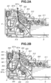
- FIG. 2A is a cross-sectional view of the drive roller 321 and a vicinity thereof, and illustrates a sheet conveyance path P of the sheet S fed from the sheet storage unit 300.
- Fig. 2B is a cross-sectional view of the drive roller 321 and the vicinity thereof, and illustrates the sheet conveyance path P of the sheet S in the case of image formation on both sides of the sheet S.
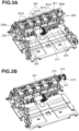
- Fig. 3A is a perspective view illustrating a configuration of the drive roller 321.
- Fig. 3B is a perspective view illustrating the configuration of the drive roller 321 in a state where a drive gear 372 and other components of a drive unit 373 (see Fig. 6A ) are attached.
- Fig. 4 is a perspective view illustrating a configuration of a duplex driven roller unit 350.
- the drive roller 321 includes a drive shaft 321a and rubber rollers 321b, and is configured to be rotated only in one direction (a counterclockwise direction in Fig. 2A ) by a driving force from a drive source 388 (refer to Fig. 1 ) included in the image forming apparatus 1.
- a drive source 388 (refer to Fig. 1 ) included in the image forming apparatus 1.
- the configuration for rotating the drive roller 321 only in one direction will be described below.
- the conveyance driven rollers 322 each serving as a first rotation member are configured to be rotated by the drive roller 321.
- the conveyance driven rollers 322 are pressed by conveyance pressing members 324 via a conveyance driven roller holder 323, and are rotated together with the drive roller 321 (are driven to rotate by the drive roller 321) while being in contact with the drive roller 321.
- the conveyance driven rollers 322 and the drive roller 321 form the first nip portion for nipping and conveying the sheet S.
- the conveyance driven rollers 322 are arranged so as to move a leading edge of the sheet S in a direction approaching the image forming portion when the leading edge of the sheet S passes through the first nip portion.
- each of the conveyance pressing members 324 is formed of a metal compression spring.
- An end portion of the metal compression spring has a shape in which a wire material is extended and in contact with a stay member 451 (refer to Fig. 10 ) formed of a sheet metal.
- the conveyance pressing members 324 are suppressed from being electrically charged due to member-to-member friction.
- Figs. 3A and 3B are perspective views each illustrating the configuration of the drive roller 321.
- the drive roller 321 includes the plurality of rubber rollers 321b provided around the drive shaft 321a, and the conveyance driven rollers 322 are respectively in contact with the corresponding rubber rollers 321b to form the first nip portion.
- the five conveyance driven rollers 322 and the five rubber rollers 321b form the first nip portion.
- a drive mechanism of the drive roller 321 will be described below.
- a conveyance direction of the sheet S before image formation on the first side is indicated by an arrow in Fig. 2A .
- the uppermost sheet S of the sheets S stacked in the sheet storage unit 300 is conveyed to the first nip portion by the pick roller 311 and the feed roller 312.
- the sheet S is conveyed from the first nip portion in a substantially vertical upward direction, and the image formation on the first side is performed at the image forming portion.
- Fig. 4 is a perspective view illustrating a configuration of the duplex driven roller unit 350.
- the duplex driven roller unit 350 is attached to a drive roller guide 325 (refer to Fig. 2B ) using a stay 351.
- Duplex driven rollers 352 each serving as a second rotation member are configured to be pressed by a duplex pressing member 354 via a driven roller shaft 353.
- the configuration including the two duplex driven rollers 352 is described, and the two duplex driven rollers 352 are arranged at positions facing two of the five rubber rollers 321b of the drive roller 321.
- the duplex driven rollers 352 each serving as the second rotation member are in contact with the drive roller 321 at positions different from those of the conveyance driven rollers 322 each serving as the first rotation member in a rotation direction of the drive roller 321.
- the conveyance driven rollers 322 are larger in diameter than the duplex driven rollers 352.
- the sheet S can be conveyed more stably without being affected by the angle at which the sheet S enters the first nip portion. For this reason, in order to convey the sheet S stably, in the present embodiment, the conveyance driven rollers 322 are larger in diameter than the duplex driven rollers 352.
- the duplex driven rollers 352 are in contact with the drive roller 321, and are configured to be rotated by the rotation of the drive roller 321 (are configured to be driven to rotate by the drive roller 321).
- the duplex driven rollers 352 and the drive roller 321 form the second nip portion for nipping and conveying the sheet S. More specifically, two of the five rubber rollers 321b, which are in contact with the duplex driven rollers 352, are each in contact with two rotation members (one conveyance driven roller 322 as the first rotation member and one duplex driven roller 352 as the second rotation member) and form two nip portions (the first nip portion and the second nip portion).
- the duplex driven rollers 352 are arranged so as to move the leading edge of the sheet S in a direction apart from the image forming portion when the leading edge of the sheet S passes through the second nip portion.
- the drive roller 321, the conveyance driven rollers 322, and the duplex driven rollers 352 are disposed below the image forming portion in a vertical direction.
- the leading edge of the sheet S passes through the second nip portion formed between the duplex driven rollers 352 and the drive roller 321, the leading edge of the sheet S moves downward in the vertical direction.
- the leading edge of the sheet S passes through the first nip portion formed between the conveyance driven rollers 322 and the drive roller 321, the leading edge of the sheet S moves upward in the vertical direction.
- the first nip portion is disposed in the sheet conveyance path P through which the sheet S passes before an image is formed on one side of the sheet S.
- the first nip portion is disposed between the sheet storage unit 300 and the image forming portion in the conveyance direction of the sheet S.
- the second nip portion is disposed in the sheet conveyance path P through which the sheet S passes during duplex printing for forming images on both sides of the sheet S. More specifically, the second nip portion is disposed in the sheet conveyance path P for conveying the sheet S with an image formed on one side thereof to the image forming portion again.
- the drive roller 321 receives pressing forces from the conveyance driven rollers 322 and the duplex driven rollers 352. However, the respective pressing forces act in directions to cancel each other, and bearings 326a and 326b (refer to Fig. 3A ) receive small forces from the drive roller 321. As a result, wear of the bearings 326a and 326b due to sliding motion with the drive roller 321 is reduced.
- the conveyance direction of the sheet S in the case of image formation on the second side is indicated by an arrow.
- the sheet S conveyed to the duplex conveyance path by the discharging/reversing roller 403 after the image formation on the first side is conveyed to the second nip portion.
- a length of the sheet conveyance path P from the second nip portion to the first nip portion is shorter than a length of the sheet S supported in duplex printing by the image forming apparatus 1.
- the drive roller 321, the conveyance driven rollers 322, the duplex driven rollers 352 can convey the sheet S in a state where the sheet S is present at the first nip portion and the second nip portion at the same time.
- a guide member 335 is provided between the second nip portion and the first nip portion in the sheet conveyance path P to guide the conveyance direction of the sheet S. Because the conveyance direction of the sheet S is largely different between the first nip portion and the second nip portion, the guide member 335 is configured to largely curve the sheet conveyance path P of the sheet S. More specifically, the guide member 335 guides the sheet S so that a moving direction of the leading edge of the sheet S changes from the direction apart from (away from) the image forming portion to the direction approaching the image forming portion. In other words, the guide member 335 guides the sheet S from a downward direction to an upward direction with respect to the vertical direction.
- An inner side conveyance guide 355 and the drive roller guide 325 form a curved guide shape of the inner side of the guide member 335.
- an outer side guide rib 361a integrally formed with a door 361 (described below), and an outer side conveyance guide 356 provided in a main body of the image forming apparatus 1 form a curved guide shape of the outer side of the guide member 335.
- the sheet S is conveyed from the second nip portion to the downward direction with respect to the vertical direction along the inner side conveyance guide 355, the sheet S is bent by the outer side guide rib 361a and the outer side conveyance guide 356, and conveyed to the first nip portion while the conveyance direction is changed to the upward direction with respect to the vertical direction.
- the sheet S in the sheet conveyance path P, while the sheet S is present at the second nip portion and first nip portion at the same time, the sheet S is conveyed in substantially opposite directions at the second nip portion and first nip portion. The sheet S is then conveyed to the image forming portion to form an image on the second side of the sheet S.
- Curvature of the curve of the sheet conveyance path P in the guide member 335 is determined by the inner side guide shape and the outer side guide shape.
- the sheet conveyance path P in the guide member 335 is formed by an outer periphery of the drive roller 321 and the outer side guide shape. Accordingly, curvature of the guide member 335 is determined by an outer diameter of the drive roller 321.
- the curvature of the curved portion of the sheet conveyance path P is to be made larger to reduce conveyance resistance of the sheet S with particularly strong stiffness.
- increasing the outer diameter of the drive roller 321 leads to an adverse effect such as a cost increase.
- the configuration according to the present embodiment achieves stable sheet conveyance by providing guide shapes on the inner side and the outer side of the guide member 335 while the outer diameter of the drive roller 321 is kept small.
- a conveyance speed of the sheet S at each of the first nip portion and the second nip portion depends on a peripheral speed of the drive roller 321.
- the drive roller 321 In a conventional configuration in which at least two drive rollers are provided, in order to eliminate manufacturing variation (dimensional tolerance) between outer diameters of the two drive rollers, accurate machining is performed and this leads to a cost increase.
- the difference in sheet conveyance speed between the two nip portions is unlikely to occur even if wear occurs in the drive roller 321 due to the manufacturing variation of the drive roller 321 or the use of the image forming apparatus 1. This makes it possible to suppress the sheet S from being excessively slack or pulled, thereby preventing image defects.
- Fig. 5 is a cross-sectional view illustrating the drive roller 321 and the vicinity thereof in a state where the door 361 is opened.
- the image forming apparatus 1 includes the door 361 and a main body frame 301 (refer to Fig. 1 ) that accommodates the image forming portion, as a housing of the image forming apparatus 1.
- the door 361 is provided to be openable and closable between an open state and a closed state, around a door rotation shaft 361b (refer to Fig. 5 ) with respect to the main body frame 301.
- a door rotation shaft 361b (refer to Fig. 5 ) with respect to the main body frame 301.
- the duplex driven roller unit 350 is held by the drive roller guide 325, and thus the duplex driven rollers 352 and the drive roller 321 form the second nip portion even when the door 361 is in the open state.
- a press-contact force at the second nip portion is applied to the main body of the image forming apparatus 1 and is not applied to the door 361.
- the press-contact forces of the duplex driven rollers 352 are applied to the door 361
- the shape and the holding mechanism thereof can be simplified, which contributes to cost reduction.
- the user can open the door 361 to perform a jam clearance operation as indicated by a dotted line in Fig. 5 .
- a large force is to be applied to pull out the sheet S nipped by the drive roller 321.
- the transmission of a driving force from the drive source 388 to the drive roller 321 is released to improve the jam clearance operability of the user. Because of the release of transmission of a driving force from the drive source 388 to the drive roller 321, in a case where the user tries to pull out the jammed sheet S toward an upstream conveyance direction (a direction indicated by an arrow in Fig. 5 ), the drive roller 321 can be easily rotated by the movement of the jammed sheet S. Thus, it is possible to perform the jam clearance operation with a small force. Also in a case where the user tries to pull out the jammed sheet S toward a downstream conveyance direction, the drive roller 321 can be easily rotated. Thus, it is possible to perform the jam clearance operation with a small force.
- FIGS. 6A and 6B are perspective views each illustrating a configuration of a drive release mechanism.
- FIGs. 7A and 7B are cross-sectional views each illustrating the configuration of the drive release mechanism.
- a driving force is transmitted from the drive source 388 to the drive roller 321
- a driving force is not transmitted from the drive source 388 to the drive roller 321.
- the drive source 388 transmits a driving force to a drive gear 372, and the driving force is transmitted to the drive roller 321 via a drive transmission member 380 and a driven transmission member 381.
- the drive gear 372, the drive transmission member 380, the driven transmission member 381, the drive roller 321, and the drive shaft 321a are provided on the same rotation shaft.
- the driven transmission member 381 and the drive roller 321 are rotated together with the drive shaft 321a.
- the drive unit 373 is held to be slidable with respect to the drive shaft 321a in a rotation axis direction.
- the drive unit 373 includes the drive gear 372 and receives a driving force from the drive source 388.
- the drive unit 373 is urged by a second urging member 387 in a direction approaching the drive roller 321 with respect to the rotation axis direction, with an urging force F2 (a second urging force) smaller than an urging force F1.
- a spring is used for the second urging member 387.
- the drive transmission member 380 and the driven transmission member 381 have a ratchet shape.
- the drive transmission member 380 transmits a driving force for rotating the sheet S in the conveyance direction to the driven transmission member 381, but does not transmit a driving force for rotating the sheet S in the opposite direction.
- the drive transmission member 380 of the drive unit 373 and the driven transmission member 381 of the drive shaft 321a are engaged with each other.
- the drive unit 373 includes the drive transmission member 380 that transmits the driving force received from the drive source 388 to the drive shaft 321a.
- the drive shaft 321a includes the driven transmission member 381 that receives the driving force from the drive transmission member 380.
- Gear teeth formed on a downstream transmission gear 371 are configured to transmit the driving force to the further downstream side, and do not contribute to the driving force transmission to the drive roller 321.
- Fig. 8 is a perspective view illustrating a drive release member 374
- Fig. 9 is a perspective view illustrating the door 361.
- an opening 383 and a pressing surface 385 are formed in the drive release member 374.
- a receiving surface 384 is formed on a side surface of the opening 383.
- a pressure receiving portion 361c is formed on the door 361. The transmission of the driving force to the drive roller 321 is released by the drive release member 374 and the pressure receiving portion 361c of the door 361. The drive release member 374 releases the transmission of the driving force by releasing the engagement of the drive transmission member 380 and the driven transmission member 381.
- An end portion of the drive release member 374 is urged by a first urging member 375 with the urging force F1 (the first urging force).
- the direction of the urging force F1 is a direction from the drive roller 321 toward the drive gear 372 with respect to the rotation axis direction of the drive roller 321.
- the image forming apparatus 1 urges the drive release member 374 with the first urging force in a direction apart from the drive roller 321 with respect to the rotation axis direction.
- a spring is used for the first urging member 375.
- the pressure receiving portion 361c provided on the door 361 and the receiving surface 384 of the drive release member 374 are in contact with each other.
- the urging force F1 applied to the drive release member 374 is received by the pressure receiving portion 361c to regulate the sliding movement of the drive release member 374.
- the drive unit 373 receives the urging force F2 in a direction approaching the drive roller 321 with respect to the rotation axis direction, and the drive transmission member 380 and the driven transmission member 381 are engaged with each other.
- the drive release member 374 is urged with the urging force F1 in a direction from the drive roller 321 toward the drive gear 372 with respect to the rotation axis direction.
- the drive release member 374 is also urged with the urging force F2 in a leftward direction in Figs. 7A and 7B .
- the relationship between the urging forces F1 and F2 is as follows: F1 > F2
- the drive release member 374 slides in the direction from the drive roller 321 toward the drive gear 372 with respect to the rotation axis direction.
- the engagement of the drive transmission member 380 and the driven transmission member 381 is released, so that a driving force is not transmitted from the drive source 388 to the drive shaft 321a and the drive roller 321.
- the driving force received by the drive gear 372 is not transmitted to the drive shaft 321a and the drive roller 321.
- Fig. 9 is a perspective view of the door 361.
- Fig. 10 is a perspective view of the image forming apparatus 1 seen from the back side thereof.
- the door 361 is provided with a detection rib 361e.
- a slope portion 361d sloped with respect to the urging force F1 is formed on the pressure receiving portion 361c.
- the image forming apparatus 1 is provided with a sensor member 386 capable of detecting the closed state of the door 361. When the door 361 is in the closed state, the closed state of the door 361 is detected by the sensor member 386 detecting the detection rib 361e provided on the door 361.
- the image forming apparatus 1 permits printing when the door 361 is in the closed state. However, if the sensor member 386 erroneously detects the closed state of the door 361 even though the door 361 is not actually in the closed state, the image forming apparatus 1 may start printing. Since the door 361 forms a part of the duplex conveyance path, if the image forming apparatus 1 starts printing when the door 361 is not in the closed state, jamming may occur during duplex printing because the duplex conveyance path is not formed in a normal manner. Thus, in one embodiment, the erroneous detection of the open state or the closed state of the door 361 can be prevented.
- the door 361 is slightly open with respect to the closed state, and the sensor member 386 detects the detection rib 361e but the guide member of the door 361 does not function sufficiently as the guide for the sheet S.
- the door 361 which is in a state between the open state and the closed state, is pushed back in a direction toward the open state by the slope portion 361d receiving the urging force F1.
- the sensor member 386 does not detect the detection rib 361e, thereby making it possible to prevent the erroneous detection of the closed state of the door 361.
- the sensor member 386 detects the detection rib 361e but the pressure receiving portion 361c does not press the drive release member 374 due to the deformation (the distortion, or the bending) of the door 361. In this state, even in a situation where the drive source 388 is to transmit a driving force to the drive roller 321, the transmission of a driving force is not possible.
- the pressure receiving portion 361c and the detection rib 361e of the door 361 are disposed on the same side with respect to a sheet conveyance region in a sheet width direction.
- the image forming apparatus 1 reduces the possibility of erroneously detecting the open state or the closed state of the door 361 due to the deformation of the door 361.
- the pressure receiving portion 361c and the detection rib 361e of the door 361 are disposed outside the sheet conveyance region in the sheet width direction.
- the duplex driven rollers 352 and the conveyance driven rollers 322 are brought into contact with the drive roller 321 to form the two nip portions. Therefore, the number of drive rollers that receive a driving force from the drive source 388 can be reduced. In addition, the size reduction and cost reduction of the main body of the image forming apparatus 1 are achieved by the space saving.
- the sheet S is conveyed at the two nip portions by the same drive roller 321, the difference in the conveyance speed of the sheet S between the two nip portions is unlikely to occur. This makes it possible to suppress the sheet S, which is being conveyed between the two nip portions, from being excessively slack or pulled, thereby preventing image defects.
- the erroneous detection of the state of the door 361 can be prevented by the drive release mechanism for the drive roller 321.
- a mechanism for correcting an inclination of the sheet S in the conveyance direction (hereinafter referred to as a skew of the sheet S).
- a regulation member 331 is provided on a downstream side of the pick roller 311 and an upstream side of the image forming portion in the conveyance direction of the sheet S in order to regulate the leading edge of the sheet S to correct the skew of the sheet S, with reference to Figs 11A and 11B .
- An overall configuration of the image forming apparatus 1 according to the present embodiment is similar to that according to the first embodiment, and thus the description thereof will be omitted.
- the image forming apparatus 1 according to the present embodiment will be described with reference to Figs. 11A and 11B .
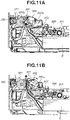
- Figs. 11A and 11B are cross-sectional views each illustrating the regulation member 331 and a vicinity thereof.
- a configuration for forming the first nip portion and the second nip portion is similar to that according to the first embodiment, and thus the description thereof will be omitted.
- the regulation member 331 for regulating the leading edge of the sheet S in the conveyance direction of the sheet S is provided on an upstream side of the first nip portion in the conveyance direction.
- the regulation member 331 is held to be rotatable around a shaft 331a and urged by an urging member 332 in a counterclockwise direction in Figs. 11A and 11B .
- a plurality of correction surfaces 331b is located on the upstream side of the first nip portion in the conveyance direction, and arranged to be bilaterally symmetrical in the width direction of the sheet S.
- the uppermost sheet S of the sheets S stacked in the sheet storage unit 300 is conveyed to the first nip portion by the pick roller 311 and the feed roller 312.
- Two different places at the leading edge of the sheet S make contact with the correction surfaces 331b of the regulation member 331 in the conveyance direction, and a position of the leading edge of the sheet S is regulated by the two places in the conveyance direction, so that the skew of the sheet S is corrected.
- the regulation member 331 is rotated in a clockwise direction in Fig. 11B by being pressed by the sheet S, so that the sheet S is conveyed to the first nip portion.
- Behavior of the sheet S in a period from the image formation on the first side to the image formation on the second side is similar to that according to the first embodiment.
- the regulation member 331 is provided on the downstream side of the pick roller 311 and the upstream side of the image forming portion in the conveyance direction of the sheet S in order to regulate the leading edge of the sheet S in the conveyance direction of the sheet S, in addition to the configuration according to the first embodiment. This makes it possible to correct the skew of the sheet S to be conveyed to the image forming portion and thereby accurately form an image on the sheet S.
- the size of an image forming apparatus can be reduced by bringing a plurality of driven rollers into contact with one drive roller so as to convey a sheet in different conveyance directions. Cost reduction can also be achieved.
Landscapes
- Physics & Mathematics (AREA)
- General Physics & Mathematics (AREA)
- Delivering By Means Of Belts And Rollers (AREA)
- Electrophotography Configuration And Component (AREA)
- Feeding Of Articles By Means Other Than Belts Or Rollers (AREA)
Abstract
Description
- The present invention relates to an image forming apparatus that forms an image on a sheet.
- There are image forming apparatuses that have an automatic duplex printing function. In such an image forming apparatus, in order to form images on both sides of a sheet, the sheet is conveyed from a sheet storage unit to an image forming portion, an image is formed on one side of the sheet, and then the sheet is reversed and conveyed to the image forming portion again. As discussed in
Japanese Patent Application Laid-open No. 2016-99430 - In this case, however, an image forming apparatus including the plurality of conveyance roller pairs needs to provide space for arranging the plurality of drive rollers each configured to receive a driving force from the image forming apparatus and the plurality of driven rollers each configured to be rotated by a corresponding one of the drive rollers. In addition, there is an issue where the cost of the image forming apparatus increases.
- According to a first aspect of the present invention, there is provided an image forming apparatus as specified in
claims 1 to 13. - Further features of the present invention will become apparent from the following description of embodiments with reference to the attached drawings.
-
-
Fig. 1 is a schematic cross-sectional view illustrating an image forming apparatus. -
Figs. 2A and 2B are cross-sectional views each illustrating a drive roller and a vicinity thereof in a state where a door is closed. -
Figs. 3A and 3B are perspective views each illustrating a configuration of the drive roller. -
Fig. 4 is a perspective view illustrating a configuration of a duplex driven roller unit. -
Fig. 5 is a cross-sectional view illustrating the drive roller and the vicinity thereof in a state where the door is open. -
Figs. 6A and 6B are perspective views each illustrating a configuration of a drive release mechanism. -
Figs. 7A and 7B are cross-sectional views each illustrating the drive release mechanism. -
Fig. 8 is a perspective view illustrating a drive release member. -
Fig. 9 is perspective view illustrating the door. -
Fig. 10 is a perspective view illustrating a back side of the image forming apparatus. -
Figs. 11A and 11B are cross-sectional views each illustrating a regulation member and a vicinity thereof. - An
image forming apparatus 1 according to a first embodiment of the present invention will be described with reference toFigs. 1 to 10 . In the present embodiment, a laser beam printer that forms an image on a sheet at an image forming portion using an electrophotographic method is described as an example of theimage forming apparatus 1. - An overall configuration of the
image forming apparatus 1 will be described with reference toFig. 1. Fig. 1 is a schematic cross-sectional view of theimage forming apparatus 1. - Sheets S stacked and stored in a
sheet storage unit 300 are fed by apick roller 311. The sheets S are separated one by one by afeed roller 312 and aseparation roller 313, and the separated sheet S is conveyed to a first nip portion formed by adrive roller 321 and conveyance drivenrollers 322. The sheet S is then conveyed to an image forming portion that is a contact portion at which aphotosensitive drum 111 included in aprocess cartridge 110 and atransfer roller 201 are in contact with each other. - In the present embodiment, the image forming portion refers to a portion at which toner serving as developer is transferred onto the sheet S.
- In the present embodiment, the contact portion of the
photosensitive drum 111 and thetransfer roller 201 is the image forming portion. In the case of a configuration using an intermediate transfer belt, a portion at which developer is transferred from the intermediate transfer belt to the sheet S is the image forming portion. - In a case where an image is to be formed on the sheet S, first, a
laser scanner unit 500 emits a laser beam to form an electrostatic latent image on thephotosensitive drum 111 serving as an image bearing member. The electrostatic latent image is developed by a developing unit (not illustrated) to form a toner image on thephotosensitive drum 111. The toner image is then transferred onto the sheet S conveyed to the image forming portion formed by thephotosensitive drum 111 and thetransfer roller 201. - The sheet S to which the toner image is transferred is conveyed to a fixing portion including a
fixing film 401 and apressure roller 402 that is brought into pressure contact with thefixing film 401. At the fixing portion, the sheet S to which the toner image is transferred is heated and pressured to fix the toner image on the sheet S. - In the case of printing on one side (a first side) of the sheet S, the sheet S on which the toner image is fixed is discharged by a discharging/reversing
roller 403 and a discharging/reversing drivenroller 404. In the case of printing on both sides of the sheet S, after a trailing edge of the sheet S passes through the fixing portion, the sheet S is conveyed to a duplex conveyance path by switching of a rotation direction of the discharging/reversingroller 403. The sheet S conveyed through the duplex conveyance path is conveyed to the image forming portion again by thedrive roller 321, and a toner image is transferred onto a second side of the sheet S. The toner image is then fixed on the sheet S at the fixing portion, and the sheet S is discharged by the discharging/reversingroller 403. - A configuration of the
drive roller 321 will be described with reference toFigs. 2A to 4 .Fig. 2A is a cross-sectional view of thedrive roller 321 and a vicinity thereof, and illustrates a sheet conveyance path P of the sheet S fed from thesheet storage unit 300.Fig. 2B is a cross-sectional view of thedrive roller 321 and the vicinity thereof, and illustrates the sheet conveyance path P of the sheet S in the case of image formation on both sides of the sheet S.Fig. 3A is a perspective view illustrating a configuration of thedrive roller 321.Fig. 3B is a perspective view illustrating the configuration of thedrive roller 321 in a state where adrive gear 372 and other components of a drive unit 373 (seeFig. 6A ) are attached.Fig. 4 is a perspective view illustrating a configuration of a duplex drivenroller unit 350. - As illustrated in
Fig. 2A , thedrive roller 321 includes adrive shaft 321a andrubber rollers 321b, and is configured to be rotated only in one direction (a counterclockwise direction inFig. 2A ) by a driving force from a drive source 388 (refer toFig. 1 ) included in theimage forming apparatus 1. The configuration for rotating thedrive roller 321 only in one direction will be described below. - The conveyance driven
rollers 322 each serving as a first rotation member are configured to be rotated by thedrive roller 321. The conveyance drivenrollers 322 are pressed byconveyance pressing members 324 via a conveyance drivenroller holder 323, and are rotated together with the drive roller 321 (are driven to rotate by the drive roller 321) while being in contact with thedrive roller 321. The conveyance drivenrollers 322 and thedrive roller 321 form the first nip portion for nipping and conveying the sheet S. The conveyance drivenrollers 322 are arranged so as to move a leading edge of the sheet S in a direction approaching the image forming portion when the leading edge of the sheet S passes through the first nip portion. - In the present embodiment, each of the
conveyance pressing members 324 is formed of a metal compression spring. An end portion of the metal compression spring has a shape in which a wire material is extended and in contact with a stay member 451 (refer toFig. 10 ) formed of a sheet metal. Thus, theconveyance pressing members 324 are suppressed from being electrically charged due to member-to-member friction. -
Figs. 3A and 3B are perspective views each illustrating the configuration of thedrive roller 321. As illustrated in inFig. 3A , thedrive roller 321 includes the plurality ofrubber rollers 321b provided around thedrive shaft 321a, and the conveyance drivenrollers 322 are respectively in contact with the correspondingrubber rollers 321b to form the first nip portion. In the present embodiment, the five conveyance drivenrollers 322 and the fiverubber rollers 321b form the first nip portion. A drive mechanism of thedrive roller 321 will be described below. - A conveyance direction of the sheet S before image formation on the first side is indicated by an arrow in
Fig. 2A . The uppermost sheet S of the sheets S stacked in thesheet storage unit 300 is conveyed to the first nip portion by thepick roller 311 and thefeed roller 312. The sheet S is conveyed from the first nip portion in a substantially vertical upward direction, and the image formation on the first side is performed at the image forming portion. -
Fig. 4 is a perspective view illustrating a configuration of the duplex drivenroller unit 350. The duplex drivenroller unit 350 is attached to a drive roller guide 325 (refer toFig. 2B ) using astay 351. Duplex drivenrollers 352 each serving as a second rotation member are configured to be pressed by aduplex pressing member 354 via a drivenroller shaft 353. - In the present embodiment, the configuration including the two duplex driven
rollers 352 is described, and the two duplex drivenrollers 352 are arranged at positions facing two of the fiverubber rollers 321b of thedrive roller 321. The duplex drivenrollers 352 each serving as the second rotation member are in contact with thedrive roller 321 at positions different from those of the conveyance drivenrollers 322 each serving as the first rotation member in a rotation direction of thedrive roller 321. - In the present embodiment, the conveyance driven
rollers 322 are larger in diameter than the duplex drivenrollers 352. There are two cases where the sheet S is conveyed to the first nip portion formed by thedrive roller 321 and the conveyance drivenrollers 322. More specifically, there is a case where the sheet S is conveyed to the first nip portion from thesheet storage unit 300, and there is a case where the sheet S is conveyed to the first nip portion from a second nip portion (described below). An angle at which the sheet S enters the first nip portion is different between the two cases. As each of the two types of rollers forming the first nip portion has a larger diameter, the sheet S can be conveyed more stably without being affected by the angle at which the sheet S enters the first nip portion. For this reason, in order to convey the sheet S stably, in the present embodiment, the conveyance drivenrollers 322 are larger in diameter than the duplex drivenrollers 352. - As illustrated in
Fig. 2B , the duplex drivenrollers 352 are in contact with thedrive roller 321, and are configured to be rotated by the rotation of the drive roller 321 (are configured to be driven to rotate by the drive roller 321). The duplex drivenrollers 352 and thedrive roller 321 form the second nip portion for nipping and conveying the sheet S. More specifically, two of the fiverubber rollers 321b, which are in contact with the duplex drivenrollers 352, are each in contact with two rotation members (one conveyance drivenroller 322 as the first rotation member and one duplex drivenroller 352 as the second rotation member) and form two nip portions (the first nip portion and the second nip portion). The duplex drivenrollers 352 are arranged so as to move the leading edge of the sheet S in a direction apart from the image forming portion when the leading edge of the sheet S passes through the second nip portion. - In the present embodiment, the
drive roller 321, the conveyance drivenrollers 322, and the duplex drivenrollers 352 are disposed below the image forming portion in a vertical direction. When the leading edge of the sheet S passes through the second nip portion formed between the duplex drivenrollers 352 and thedrive roller 321, the leading edge of the sheet S moves downward in the vertical direction. When the leading edge of the sheet S passes through the first nip portion formed between the conveyance drivenrollers 322 and thedrive roller 321, the leading edge of the sheet S moves upward in the vertical direction. - The first nip portion is disposed in the sheet conveyance path P through which the sheet S passes before an image is formed on one side of the sheet S. The first nip portion is disposed between the
sheet storage unit 300 and the image forming portion in the conveyance direction of the sheet S. The second nip portion is disposed in the sheet conveyance path P through which the sheet S passes during duplex printing for forming images on both sides of the sheet S. More specifically, the second nip portion is disposed in the sheet conveyance path P for conveying the sheet S with an image formed on one side thereof to the image forming portion again. - The
drive roller 321 receives pressing forces from the conveyance drivenrollers 322 and the duplex drivenrollers 352. However, the respective pressing forces act in directions to cancel each other, andbearings Fig. 3A ) receive small forces from thedrive roller 321. As a result, wear of thebearings drive roller 321 is reduced. - In
Fig. 2B , the conveyance direction of the sheet S in the case of image formation on the second side is indicated by an arrow. In duplex printing, the sheet S conveyed to the duplex conveyance path by the discharging/reversingroller 403 after the image formation on the first side is conveyed to the second nip portion. A length of the sheet conveyance path P from the second nip portion to the first nip portion is shorter than a length of the sheet S supported in duplex printing by theimage forming apparatus 1. Thus, thedrive roller 321, the conveyance drivenrollers 322, the duplex drivenrollers 352 can convey the sheet S in a state where the sheet S is present at the first nip portion and the second nip portion at the same time. - A
guide member 335 is provided between the second nip portion and the first nip portion in the sheet conveyance path P to guide the conveyance direction of the sheet S. Because the conveyance direction of the sheet S is largely different between the first nip portion and the second nip portion, theguide member 335 is configured to largely curve the sheet conveyance path P of the sheet S. More specifically, theguide member 335 guides the sheet S so that a moving direction of the leading edge of the sheet S changes from the direction apart from (away from) the image forming portion to the direction approaching the image forming portion. In other words, theguide member 335 guides the sheet S from a downward direction to an upward direction with respect to the vertical direction. - An inner
side conveyance guide 355 and thedrive roller guide 325 form a curved guide shape of the inner side of theguide member 335. In addition, an outerside guide rib 361a integrally formed with a door 361 (described below), and an outerside conveyance guide 356 provided in a main body of theimage forming apparatus 1 form a curved guide shape of the outer side of theguide member 335. - After the sheet S is conveyed from the second nip portion to the downward direction with respect to the vertical direction along the inner
side conveyance guide 355, the sheet S is bent by the outerside guide rib 361a and the outerside conveyance guide 356, and conveyed to the first nip portion while the conveyance direction is changed to the upward direction with respect to the vertical direction. - In this case, in the sheet conveyance path P, while the sheet S is present at the second nip portion and first nip portion at the same time, the sheet S is conveyed in substantially opposite directions at the second nip portion and first nip portion. The sheet S is then conveyed to the image forming portion to form an image on the second side of the sheet S.
- Curvature of the curve of the sheet conveyance path P in the
guide member 335 is determined by the inner side guide shape and the outer side guide shape. In the case of a configuration in which no inner side guide is provided in theguide member 335, the sheet conveyance path P in theguide member 335 is formed by an outer periphery of thedrive roller 321 and the outer side guide shape. Accordingly, curvature of theguide member 335 is determined by an outer diameter of thedrive roller 321. To achieve stable sheet conveyance, the curvature of the curved portion of the sheet conveyance path P is to be made larger to reduce conveyance resistance of the sheet S with particularly strong stiffness. On the other hand, increasing the outer diameter of thedrive roller 321 leads to an adverse effect such as a cost increase. The configuration according to the present embodiment achieves stable sheet conveyance by providing guide shapes on the inner side and the outer side of theguide member 335 while the outer diameter of thedrive roller 321 is kept small. - A conveyance speed of the sheet S at each of the first nip portion and the second nip portion depends on a peripheral speed of the
drive roller 321. In a conventional configuration in which at least two drive rollers are provided, in order to eliminate manufacturing variation (dimensional tolerance) between outer diameters of the two drive rollers, accurate machining is performed and this leads to a cost increase. - It is also conceivable that wear occurs in the drive rollers due to the conveyance of the sheet S, and wear amounts of the two drive rollers differ. For this reason, there is a possibility that a difference in peripheral speed between the two drive rollers may increase through the use of the image forming apparatus. If there is a difference in peripheral speed between the two drive rollers, i.e., a difference in sheet conveyance speed between the two nip portions, there is a possibility that the sheet S may be slack or pulled and an image defect may occur due to the sheet S being rubbed strongly against the guide member.
- On the other hand, in the configuration according to the present embodiment, since the two nip portions are formed using the
single drive roller 321, the difference in sheet conveyance speed between the two nip portions is unlikely to occur even if wear occurs in thedrive roller 321 due to the manufacturing variation of thedrive roller 321 or the use of theimage forming apparatus 1. This makes it possible to suppress the sheet S from being excessively slack or pulled, thereby preventing image defects. - Jam clearance operability of the
image forming apparatus 1 according to the present embodiment will be described with reference toFig. 5. Fig. 5 is a cross-sectional view illustrating thedrive roller 321 and the vicinity thereof in a state where thedoor 361 is opened. - The
image forming apparatus 1 includes thedoor 361 and a main body frame 301 (refer toFig. 1 ) that accommodates the image forming portion, as a housing of theimage forming apparatus 1. Thedoor 361 is provided to be openable and closable between an open state and a closed state, around adoor rotation shaft 361b (refer toFig. 5 ) with respect to themain body frame 301. When thedoor 361 is in the open state, the sheet conveyance path P is exposed, so that the user can remove the jammed sheet S. - The duplex driven
roller unit 350 is held by thedrive roller guide 325, and thus the duplex drivenrollers 352 and thedrive roller 321 form the second nip portion even when thedoor 361 is in the open state. In the configuration according to the present embodiment, a press-contact force at the second nip portion is applied to the main body of theimage forming apparatus 1 and is not applied to thedoor 361. Thus, compared with a case where the press-contact forces of the duplex drivenrollers 352 are applied to thedoor 361, it is possible to reduce the stiffness of thedoor 361 and a holding force for holding the closed state of thedoor 361. Thus, the shape and the holding mechanism thereof can be simplified, which contributes to cost reduction. - In the present embodiment, if a jam occurs, the user can open the
door 361 to perform a jam clearance operation as indicated by a dotted line inFig. 5 . However, in a state where a driving force is transmitted from thedrive source 388 to thedrive roller 321, a large force is to be applied to pull out the sheet S nipped by thedrive roller 321. - To address the issue, in the configuration according to the present embodiment, when the
door 361 is in the open state, the transmission of a driving force from thedrive source 388 to thedrive roller 321 is released to improve the jam clearance operability of the user. Because of the release of transmission of a driving force from thedrive source 388 to thedrive roller 321, in a case where the user tries to pull out the jammed sheet S toward an upstream conveyance direction (a direction indicated by an arrow inFig. 5 ), thedrive roller 321 can be easily rotated by the movement of the jammed sheet S. Thus, it is possible to perform the jam clearance operation with a small force. Also in a case where the user tries to pull out the jammed sheet S toward a downstream conveyance direction, thedrive roller 321 can be easily rotated. Thus, it is possible to perform the jam clearance operation with a small force. - A method for transmitting a driving force to the
drive roller 321 will be described with reference toFigs. 6A and 6B andFigs. 7A and 7B .Figs. 6A and 6B are perspective views each illustrating a configuration of a drive release mechanism.Figs. 7A and 7B are cross-sectional views each illustrating the configuration of the drive release mechanism. In the configuration according to the present embodiment, when thedoor 361 is in the closed state as illustrated inFigs. 6A and7A , a driving force is transmitted from thedrive source 388 to thedrive roller 321, and when thedoor 361 is in the open state as illustrated inFigs. 6B and7B , a driving force is not transmitted from thedrive source 388 to thedrive roller 321. - As illustrated in
Figs. 7A and 7B , thedrive source 388 transmits a driving force to adrive gear 372, and the driving force is transmitted to thedrive roller 321 via adrive transmission member 380 and a driventransmission member 381. Thedrive gear 372, thedrive transmission member 380, the driventransmission member 381, thedrive roller 321, and thedrive shaft 321a are provided on the same rotation shaft. The driventransmission member 381 and thedrive roller 321 are rotated together with thedrive shaft 321a. - The
drive unit 373 is held to be slidable with respect to thedrive shaft 321a in a rotation axis direction. Thedrive unit 373 includes thedrive gear 372 and receives a driving force from thedrive source 388. Thedrive unit 373 is urged by asecond urging member 387 in a direction approaching thedrive roller 321 with respect to the rotation axis direction, with an urging force F2 (a second urging force) smaller than an urging force F1. In the present embodiment, a spring is used for thesecond urging member 387. - The
drive transmission member 380 and the driventransmission member 381 have a ratchet shape. Thus, thedrive transmission member 380 transmits a driving force for rotating the sheet S in the conveyance direction to the driventransmission member 381, but does not transmit a driving force for rotating the sheet S in the opposite direction. - In the state illustrated in
Figs. 6A and7A where thedoor 361 is in the closed state, thedrive transmission member 380 of thedrive unit 373 and the driventransmission member 381 of thedrive shaft 321a are engaged with each other. Thus, when thedrive source 388 transmits a driving force to thedrive gear 372, thedrive transmission member 380 transmits the driving force to the driventransmission member 381 to rotate thedrive shaft 321a. In other words, thedrive unit 373 includes thedrive transmission member 380 that transmits the driving force received from thedrive source 388 to thedrive shaft 321a. Thedrive shaft 321a includes the driventransmission member 381 that receives the driving force from thedrive transmission member 380. - On the other hand, in the state illustrated in
Figs. 6B and7B where thedoor 361 is in the open state, since thedrive transmission member 380 and the driventransmission member 381 are not engaged with each other, the driving force received by thedrive gear 372 from thedrive source 388 is not transmitted to the driventransmission member 381. Accordingly, thedrive shaft 321a does not rotate, and thus thedrive roller 321 does not rotate either. - Gear teeth formed on a
downstream transmission gear 371 are configured to transmit the driving force to the further downstream side, and do not contribute to the driving force transmission to thedrive roller 321. - As described above, whether to transmit the driving force from the
drive gear 372 to thedrive roller 321 is determined based on whether thedoor 361 is in the open state or the closed state, i.e., whether thedrive transmission member 380 and the driventransmission member 381 are engaged with each other. Next, a description will be given of how thedrive transmission member 380 and the driventransmission member 381 are engaged and the engagement thereof is released in each of the open state and the closed state of thedoor 361.Fig. 8 is a perspective view illustrating adrive release member 374, andFig. 9 is a perspective view illustrating thedoor 361. - As illustrated in
Fig. 8 , anopening 383 and apressing surface 385 are formed in thedrive release member 374. A receivingsurface 384 is formed on a side surface of theopening 383. As illustrated inFig. 9 , apressure receiving portion 361c is formed on thedoor 361. The transmission of the driving force to thedrive roller 321 is released by thedrive release member 374 and thepressure receiving portion 361c of thedoor 361. Thedrive release member 374 releases the transmission of the driving force by releasing the engagement of thedrive transmission member 380 and the driventransmission member 381. - First, an operation performed when the
door 361 is in the closed state will be described with reference toFigs. 6A and7A . When thedoor 361 is in the closed state, a driving force is transmitted from thedrive source 388 to thedrive roller 321. Thedrive release member 374 is held to be slidable in the rotation axis direction of thedrive roller 321. - An end portion of the
drive release member 374 is urged by a first urgingmember 375 with the urging force F1 (the first urging force). The direction of the urging force F1 is a direction from thedrive roller 321 toward thedrive gear 372 with respect to the rotation axis direction of thedrive roller 321. In other words, theimage forming apparatus 1 urges thedrive release member 374 with the first urging force in a direction apart from thedrive roller 321 with respect to the rotation axis direction. In the present embodiment, a spring is used for the first urgingmember 375. - When the
door 361 is in the closed state, thepressure receiving portion 361c provided on thedoor 361 and the receivingsurface 384 of thedrive release member 374 are in contact with each other. Thus, the urging force F1 applied to thedrive release member 374 is received by thepressure receiving portion 361c to regulate the sliding movement of thedrive release member 374. Thus, thedrive unit 373 receives the urging force F2 in a direction approaching thedrive roller 321 with respect to the rotation axis direction, and thedrive transmission member 380 and the driventransmission member 381 are engaged with each other. - In this way, when the
door 361 is in the closed state, the driving force received by thedrive gear 372 is transmitted to thedrive shaft 321a and thedrive roller 321. In this state, there is a space between thepressing surface 385 and thedrive unit 373. On the other hand, when thedoor 361 is in the open state, thedrive release member 374 urges thedrive unit 373 in the direction apart from thedrive roller 321 with respect to the rotation axis direction. - Next, driving force transmission in case where the
door 361 is in the open state will be described with reference toFigs. 6B and7B . When thedoor 361 is in the open state, a driving force is not transmitted from thedrive source 388 to thedrive roller 321. When thedoor 361 is in the open state, thepressure receiving portion 361c is retracted from theopening 383 of thedrive release member 374. - Accordingly, the
drive release member 374 is urged with the urging force F1 in a direction from thedrive roller 321 toward thedrive gear 372 with respect to the rotation axis direction. Thedrive release member 374 is also urged with the urging force F2 in a leftward direction inFigs. 7A and 7B . The relationship between the urging forces F1 and F2 is as follows:
F1 > F2 - Thus, the
drive release member 374 slides in the direction from thedrive roller 321 toward thedrive gear 372 with respect to the rotation axis direction. This causes thedrive unit 373 to slide in the direction from thedrive roller 321 toward thedrive gear 372 with respect to the rotation axis direction. Accordingly, the engagement of thedrive transmission member 380 and the driventransmission member 381 is released, so that a driving force is not transmitted from thedrive source 388 to thedrive shaft 321a and thedrive roller 321. In this way, when thedoor 361 is in the open state, the driving force received by thedrive gear 372 is not transmitted to thedrive shaft 321a and thedrive roller 321. - A description will be given of a function of preventing erroneous detection of the open state or the closed state of the
door 361 in the configuration according to the present embodiment, with reference toFigs. 9 and10 .Fig. 9 is a perspective view of thedoor 361.Fig. 10 is a perspective view of theimage forming apparatus 1 seen from the back side thereof. - As illustrated in
Fig. 9 , thedoor 361 is provided with adetection rib 361e. Aslope portion 361d sloped with respect to the urging force F1 is formed on thepressure receiving portion 361c. As illustrated inFig. 10 , theimage forming apparatus 1 is provided with asensor member 386 capable of detecting the closed state of thedoor 361. When thedoor 361 is in the closed state, the closed state of thedoor 361 is detected by thesensor member 386 detecting thedetection rib 361e provided on thedoor 361. - Normally, the
image forming apparatus 1 permits printing when thedoor 361 is in the closed state. However, if thesensor member 386 erroneously detects the closed state of thedoor 361 even though thedoor 361 is not actually in the closed state, theimage forming apparatus 1 may start printing. Since thedoor 361 forms a part of the duplex conveyance path, if theimage forming apparatus 1 starts printing when thedoor 361 is not in the closed state, jamming may occur during duplex printing because the duplex conveyance path is not formed in a normal manner. Thus, in one embodiment, the erroneous detection of the open state or the closed state of thedoor 361 can be prevented. - As an example of the erroneous detection of the state of the
door 361, the following state is conceivable. Thedoor 361 is slightly open with respect to the closed state, and thesensor member 386 detects thedetection rib 361e but the guide member of thedoor 361 does not function sufficiently as the guide for the sheet S. - With the configuration according to the present embodiment, such erroneous detection can be prevented. When the user performs an operation for changing the
door 361 from the open state to the closed state (hereinafter referred to as a closing operation), thedrive release member 374 moves in a direction against the urging force F1 with respect to the rotation axis direction while the receivingsurface 384 is in contact with theslope portion 361d of thedoor 361. - At this time, if the user stops the closing operation in the middle or the
door 361 is not completely closed, thedoor 361, which is in a state between the open state and the closed state, is pushed back in a direction toward the open state by theslope portion 361d receiving the urging force F1. Thus, thesensor member 386 does not detect thedetection rib 361e, thereby making it possible to prevent the erroneous detection of the closed state of thedoor 361. - As another example of the erroneous detection, a case is conceivable where the
sensor member 386 detects thedetection rib 361e but thepressure receiving portion 361c does not press thedrive release member 374 due to the deformation (the distortion, or the bending) of thedoor 361. In this state, even in a situation where thedrive source 388 is to transmit a driving force to thedrive roller 321, the transmission of a driving force is not possible. - To prevent the situation, as illustrated in
Fig. 10 , thepressure receiving portion 361c and thedetection rib 361e of thedoor 361 are disposed on the same side with respect to a sheet conveyance region in a sheet width direction. With this configuration, theimage forming apparatus 1 reduces the possibility of erroneously detecting the open state or the closed state of thedoor 361 due to the deformation of thedoor 361. Thepressure receiving portion 361c and thedetection rib 361e of thedoor 361 are disposed outside the sheet conveyance region in the sheet width direction. - As described above, according to the present embodiment, the duplex driven
rollers 352 and the conveyance drivenrollers 322 are brought into contact with thedrive roller 321 to form the two nip portions. Therefore, the number of drive rollers that receive a driving force from thedrive source 388 can be reduced. In addition, the size reduction and cost reduction of the main body of theimage forming apparatus 1 are achieved by the space saving. - Furthermore, since the sheet S is conveyed at the two nip portions by the
same drive roller 321, the difference in the conveyance speed of the sheet S between the two nip portions is unlikely to occur. This makes it possible to suppress the sheet S, which is being conveyed between the two nip portions, from being excessively slack or pulled, thereby preventing image defects. - Moreover, even in a state where the closing operation of the
door 361 is not completely performed, the erroneous detection of the state of thedoor 361 can be prevented by the drive release mechanism for thedrive roller 321. - In the configuration according to the first embodiment where the duplex driven
rollers 352 and the conveyance drivenrollers 322 are brought into contact with thedrive roller 321 to form the two nip portions, it is also possible to provide a mechanism for correcting an inclination of the sheet S in the conveyance direction (hereinafter referred to as a skew of the sheet S). In a second embodiment, a description will be given of a configuration in which aregulation member 331 is provided on a downstream side of thepick roller 311 and an upstream side of the image forming portion in the conveyance direction of the sheet S in order to regulate the leading edge of the sheet S to correct the skew of the sheet S, with reference toFigs 11A and 11B . An overall configuration of theimage forming apparatus 1 according to the present embodiment is similar to that according to the first embodiment, and thus the description thereof will be omitted. Theimage forming apparatus 1 according to the present embodiment will be described with reference toFigs. 11A and 11B . -
Figs. 11A and 11B are cross-sectional views each illustrating theregulation member 331 and a vicinity thereof. A configuration for forming the first nip portion and the second nip portion is similar to that according to the first embodiment, and thus the description thereof will be omitted. Theregulation member 331 for regulating the leading edge of the sheet S in the conveyance direction of the sheet S is provided on an upstream side of the first nip portion in the conveyance direction. Theregulation member 331 is held to be rotatable around ashaft 331a and urged by an urgingmember 332 in a counterclockwise direction inFigs. 11A and 11B . A plurality ofcorrection surfaces 331b is located on the upstream side of the first nip portion in the conveyance direction, and arranged to be bilaterally symmetrical in the width direction of the sheet S. - As illustrated in
Fig. 11A , the uppermost sheet S of the sheets S stacked in thesheet storage unit 300 is conveyed to the first nip portion by thepick roller 311 and thefeed roller 312. Two different places at the leading edge of the sheet S make contact with the correction surfaces 331b of theregulation member 331 in the conveyance direction, and a position of the leading edge of the sheet S is regulated by the two places in the conveyance direction, so that the skew of the sheet S is corrected. Then, as illustrated inFig. 11B , theregulation member 331 is rotated in a clockwise direction inFig. 11B by being pressed by the sheet S, so that the sheet S is conveyed to the first nip portion. - Behavior of the sheet S in a period from the image formation on the first side to the image formation on the second side is similar to that according to the first embodiment.
- As described above, according to the present embodiment, the
regulation member 331 is provided on the downstream side of thepick roller 311 and the upstream side of the image forming portion in the conveyance direction of the sheet S in order to regulate the leading edge of the sheet S in the conveyance direction of the sheet S, in addition to the configuration according to the first embodiment. This makes it possible to correct the skew of the sheet S to be conveyed to the image forming portion and thereby accurately form an image on the sheet S. - According to the embodiments of the present invention, the size of an image forming apparatus can be reduced by bringing a plurality of driven rollers into contact with one drive roller so as to convey a sheet in different conveyance directions. Cost reduction can also be achieved.
- While the present invention has been described with reference to embodiments, it is to be understood that the invention is not limited to the disclosed embodiments but is defined by the scope of the following claims.
Claims (13)
- An image forming apparatus (1) comprising:an image forming portion at which developer is transferred onto a sheet;a drive roller (321) configured to be rotated by a drive source (388);a first rotation member (322) disposed in contact with the drive roller and configured to be driven to rotate by the drive roller, the first rotation member and the drive roller forming a first nip portion for nipping the sheet; anda second rotation member (352) disposed in contact with the drive roller at a position different from a position of the first rotation member in a rotation direction of the drive roller, and configured to be driven to rotate by the drive roller, the second rotation member and the drive roller forming a second nip portion for nipping the sheet,wherein the drive roller (321), the first rotation member (322), and the second rotation member (352) are arranged so as to move a leading edge of the sheet in a direction approaching the image forming portion in a case where the leading edge passes through the first nip portion, and so as to move the leading edge in a direction apart from the image forming portion in a case where the leading edge passes through the second nip portion, andwherein the drive roller (321), the first rotation member (322), and the second rotation member (352) are configured to convey the sheet in a state where the sheet is present at the first nip portion and the second nip portion at a same time.
- The image forming apparatus according to claim 1, wherein the first and second rotation members (322, 352) are arranged such that pressing forces from the first and second rotation members on the drive roller (321) act in opposite directions.
- The image forming apparatus according to any one of the preceding claims, wherein the drive roller (321) is rotated in one direction by a driving force from the drive source (388).
- The image forming apparatus according to any one of the preceding claims, further comprising a guide member (335) configured to guide the sheet so as to change a moving direction of the leading edge from the direction apart from the image forming portion to the direction approaching the image forming portion and guide the sheet from the second nip portion to the first nip portion.
- The image forming apparatus according to any one of the preceding claims, further comprising:sheet storage means (300) for stacking and storing the sheet;a pick roller (311) configured to feed the sheet stacked and stored in the sheet storage means; anda regulation member (331) disposed on a downstream side of the pick roller and an upstream side of the image forming portion in a conveyance direction of the sheet, and configured to regulate the leading edge of the sheet to correct a skew of the sheet.
- The image forming apparatus according to any one of the preceding claims, wherein the first rotation member (322) is larger in diameter than the second rotation member (352).
- The image forming apparatus according to any one of the preceding claims, further comprising:a main body frame (301) configured to accommodate the image forming portion; anda door (361) configured to be openable and closable with respect to the main body frame,wherein, in a case where the door is in a closed state, a driving force is transmitted from the drive source (388) to the drive roller (321), andwherein, in a case where the door is in an open state, the driving force is not transmitted from the drive source to the drive roller.
- The image forming apparatus according to claim 7, wherein, in the case where the door (361) is in the open state, the second rotation member (352) and the drive roller (321) form the second nip portion.
- The image forming apparatus according to claim 7 or 8, further comprising drive means configured to receive the driving force from the drive source (388),wherein the drive roller (321) is rotated together with a drive shaft (321a),wherein the drive means includes a drive transmission member (380) configured to transmit the driving force received from the drive source (388) to the drive shaft (321a), andwherein the drive shaft (321a) includes a driven transmission member (381) configured to receive the driving force from the drive transmission member (380).
- The image forming apparatus according to claim 9, wherein movement of the drive means toward the drive roller (321) in a rotation axis direction of the drive shaft (321a) causes engagement of the drive transmission member (380) and the driven transmission member (381).
- The image forming apparatus according to claim 10, further comprising a drive release member (374) configured to release the engagement of the drive transmission member (380) and the driven transmission member (381),
wherein the drive release member (374) is configured to urge the drive means in a direction apart from the drive roller (321) with respect to the rotation axis direction, in a case where the door (361) becomes the open state. - The image forming apparatus according to claim 11,wherein the drive release member (374) is urged with a first urging force in the direction apart from the drive roller (321) with respect to the rotation axis direction,wherein the drive means is urged with a second urging force smaller than the first urging force in a direction approaching the drive roller (321) with respect to the rotation axis direction,wherein the door (361) includes a pressure receiving portion (361c),wherein the drive release member (374) has an opening, andwherein, in the case where the door is in the closed state, the pressure receiving portion is brought into contact with the drive release member and receives the first urging force to enable the drive means to move toward the drive roller in the rotation axis direction.
- The image forming apparatus according to claim 12,wherein the pressure receiving portion (361c) includes a slope portion sloped toward a direction urged by the first urging force, andwherein the slope portion is configured to receive the first urging force to cause the door to open, in a case where the door (361) is in a state between the open state and the closed state.
Applications Claiming Priority (1)
| Application Number | Priority Date | Filing Date | Title |
|---|---|---|---|
| JP2021122287A JP2023018277A (en) | 2021-07-27 | 2021-07-27 | image forming device |
Publications (2)
| Publication Number | Publication Date |
|---|---|
| EP4124914A1 true EP4124914A1 (en) | 2023-02-01 |
| EP4124914B1 EP4124914B1 (en) | 2024-10-09 |
Family
ID=82656595
Family Applications (1)
| Application Number | Title | Priority Date | Filing Date |
|---|---|---|---|
| EP22185799.8A Active EP4124914B1 (en) | 2021-07-27 | 2022-07-19 | Image forming apparatus |
Country Status (4)
| Country | Link |
|---|---|
| US (1) | US12025946B2 (en) |
| EP (1) | EP4124914B1 (en) |
| JP (1) | JP2023018277A (en) |
| CN (1) | CN115685708A (en) |
Citations (5)
| Publication number | Priority date | Publication date | Assignee | Title |
|---|---|---|---|---|
| JP2000026002A (en) * | 1998-07-14 | 2000-01-25 | Matsushita Electric Ind Co Ltd | Image forming apparatus with double-sided printing mechanism |
| US20010031155A1 (en) * | 2000-02-25 | 2001-10-18 | Yasushi Hashimoto | Image forming apparatus |
| JP4072892B2 (en) * | 2002-05-21 | 2008-04-09 | 京セラミタ株式会社 | Automatic document feeder and image forming apparatus |
| JP2016099430A (en) | 2014-11-19 | 2016-05-30 | キヤノン株式会社 | Image forming apparatus |
| US20170255138A1 (en) * | 2016-03-01 | 2017-09-07 | Kyocera Document Solutions Inc. | Image forming apparatus |
Family Cites Families (18)
| Publication number | Priority date | Publication date | Assignee | Title |
|---|---|---|---|---|
| JP2840734B2 (en) * | 1989-03-29 | 1998-12-24 | キヤノン株式会社 | Image forming device |
| JPH10178508A (en) * | 1996-12-19 | 1998-06-30 | Murata Mach Ltd | Original reader and communication device |
| US6078765A (en) * | 1997-10-28 | 2000-06-20 | Canon Kabushiki Kaisha | Image forming apparatus |
| JP3520850B2 (en) * | 2000-11-20 | 2004-04-19 | 村田機械株式会社 | Image forming device |
| JP2002365862A (en) * | 2001-06-04 | 2002-12-18 | Ricoh Co Ltd | Image forming device |
| JP5213529B2 (en) * | 2008-06-09 | 2013-06-19 | キヤノン株式会社 | Image processing device |
| JP2010241519A (en) * | 2009-04-01 | 2010-10-28 | Kyocera Mita Corp | Paper reversing device and image forming apparatus |
| JP5633187B2 (en) * | 2010-05-20 | 2014-12-03 | 株式会社リコー | Sheet feeding device and automatic document feeder |
| JP5454500B2 (en) * | 2011-03-18 | 2014-03-26 | コニカミノルタ株式会社 | Paper transport device, image forming apparatus, paper transport device control method, and paper transport device control program |
| US9388005B2 (en) * | 2012-02-08 | 2016-07-12 | Canon Kabushiki Kaisha | Sheet conveying apparatus and image forming apparatus |
| JP6411138B2 (en) * | 2014-09-01 | 2018-10-24 | シャープ株式会社 | Paper transport device, document feeder, and image forming apparatus |
| JP5970520B2 (en) * | 2014-10-16 | 2016-08-17 | 京セラドキュメントソリューションズ株式会社 | Sheet conveying apparatus and image forming apparatus provided with the same |
| US9791814B2 (en) * | 2015-04-09 | 2017-10-17 | Canon Kabushiki Kaisha | Image forming apparatus |
| JP6800773B2 (en) * | 2016-03-28 | 2020-12-16 | キヤノン株式会社 | Sheet transfer device, image forming device, and image reading device |
| JP2018177517A (en) * | 2017-04-21 | 2018-11-15 | キヤノン株式会社 | Sheet conveying apparatus, image forming apparatus, and image reading apparatus |
| JP7131128B2 (en) * | 2018-06-28 | 2022-09-06 | セイコーエプソン株式会社 | recording device |
| JP2021079601A (en) * | 2019-11-18 | 2021-05-27 | セイコーエプソン株式会社 | Medium conveying device and processing device |
| JP7455571B2 (en) * | 2019-12-23 | 2024-03-26 | キヤノン株式会社 | Sheet feeding device and image forming device |
-
2021
- 2021-07-27 JP JP2021122287A patent/JP2023018277A/en active Pending
-
2022
- 2022-07-18 CN CN202210841293.0A patent/CN115685708A/en active Pending
- 2022-07-19 EP EP22185799.8A patent/EP4124914B1/en active Active
- 2022-07-20 US US17/869,686 patent/US12025946B2/en active Active
Patent Citations (5)
| Publication number | Priority date | Publication date | Assignee | Title |
|---|---|---|---|---|
| JP2000026002A (en) * | 1998-07-14 | 2000-01-25 | Matsushita Electric Ind Co Ltd | Image forming apparatus with double-sided printing mechanism |
| US20010031155A1 (en) * | 2000-02-25 | 2001-10-18 | Yasushi Hashimoto | Image forming apparatus |
| JP4072892B2 (en) * | 2002-05-21 | 2008-04-09 | 京セラミタ株式会社 | Automatic document feeder and image forming apparatus |
| JP2016099430A (en) | 2014-11-19 | 2016-05-30 | キヤノン株式会社 | Image forming apparatus |
| US20170255138A1 (en) * | 2016-03-01 | 2017-09-07 | Kyocera Document Solutions Inc. | Image forming apparatus |
Also Published As
| Publication number | Publication date |
|---|---|
| JP2023018277A (en) | 2023-02-08 |
| US20230031782A1 (en) | 2023-02-02 |
| CN115685708A (en) | 2023-02-03 |
| EP4124914B1 (en) | 2024-10-09 |
| US12025946B2 (en) | 2024-07-02 |
Similar Documents
| Publication | Publication Date | Title |
|---|---|---|
| US6260840B1 (en) | Sheet feeding apparatus, image forming apparatus having the same and image reading apparatus having the same | |
| US11655113B2 (en) | Sheet conveyance apparatus, image reading apparatus and image forming apparatus | |
| US7690639B2 (en) | Sheet conveying device, and image forming apparatus including same | |
| US11713204B2 (en) | Sheet conveying apparatus, image reading apparatus, and image forming apparatus | |
| US20160101956A1 (en) | Sheet detecting apparatus, sheet conveying apparatus, and image forming apparatus | |
| US10538411B2 (en) | Sheet conveying device | |
| US12037216B2 (en) | Conveyance device and image forming apparatus | |
| US20090028619A1 (en) | Image forming apparatus | |
| US20110236096A1 (en) | Image Forming Apparatus | |
| US10988334B2 (en) | Sheet conveyance apparatus and image forming apparatus | |
| CN113219801A (en) | Document conveying apparatus, image reading apparatus, and image forming apparatus | |
| US10435260B2 (en) | Sheet conveying apparatus, image forming apparatus, and image reading apparatus to change the sheet conveying direction by moving a rotating member that conveys the sheet | |
| EP4124914B1 (en) | Image forming apparatus | |
| US9885988B2 (en) | Sheet conveying apparatus and image forming apparatus including same | |
| US11619902B2 (en) | Conveyance control for image forming apparatus | |
| US10556762B2 (en) | Sheet conveying apparatus, image forming apparatus, and image reading apparatus | |
| JP2010155681A (en) | Sheet ejecting device and image forming device | |
| JP2008170787A (en) | Image forming apparatus | |
| US12459769B2 (en) | Sheet conveying apparatus and image forming apparatus | |
| JP7750675B2 (en) | Sheet processing apparatus and image forming system | |
| US12358742B2 (en) | Conveyance apparatus and image forming apparatus | |
| US10310436B2 (en) | Sheet discharge device | |
| JP5029410B2 (en) | Image forming apparatus and paper feeding mechanism | |
| JP2009007087A (en) | Image forming apparatus | |
| JP6218472B2 (en) | Image forming apparatus |
Legal Events
| Date | Code | Title | Description |
|---|---|---|---|
| PUAI | Public reference made under article 153(3) epc to a published international application that has entered the european phase |
Free format text: ORIGINAL CODE: 0009012 |
|
| STAA | Information on the status of an ep patent application or granted ep patent |
Free format text: STATUS: THE APPLICATION HAS BEEN PUBLISHED |
|
| AK | Designated contracting states |
Kind code of ref document: A1 Designated state(s): AL AT BE BG CH CY CZ DE DK EE ES FI FR GB GR HR HU IE IS IT LI LT LU LV MC MK MT NL NO PL PT RO RS SE SI SK SM TR |
|
| STAA | Information on the status of an ep patent application or granted ep patent |
Free format text: STATUS: REQUEST FOR EXAMINATION WAS MADE |
|
| 17P | Request for examination filed |
Effective date: 20230801 |
|
| RBV | Designated contracting states (corrected) |
Designated state(s): AL AT BE BG CH CY CZ DE DK EE ES FI FR GB GR HR HU IE IS IT LI LT LU LV MC MK MT NL NO PL PT RO RS SE SI SK SM TR |
|
| GRAP | Despatch of communication of intention to grant a patent |
Free format text: ORIGINAL CODE: EPIDOSNIGR1 |
|
| STAA | Information on the status of an ep patent application or granted ep patent |
Free format text: STATUS: GRANT OF PATENT IS INTENDED |
|
| RIC1 | Information provided on ipc code assigned before grant |
Ipc: G03G 21/16 20060101ALI20231121BHEP Ipc: G03G 15/00 20060101ALI20231121BHEP Ipc: G03G 15/23 20060101AFI20231121BHEP |
|
| INTG | Intention to grant announced |
Effective date: 20231212 |
|
| GRAJ | Information related to disapproval of communication of intention to grant by the applicant or resumption of examination proceedings by the epo deleted |
Free format text: ORIGINAL CODE: EPIDOSDIGR1 |
|
| STAA | Information on the status of an ep patent application or granted ep patent |
Free format text: STATUS: REQUEST FOR EXAMINATION WAS MADE |
|
| INTC | Intention to grant announced (deleted) | ||
| GRAP | Despatch of communication of intention to grant a patent |
Free format text: ORIGINAL CODE: EPIDOSNIGR1 |
|
| STAA | Information on the status of an ep patent application or granted ep patent |
Free format text: STATUS: GRANT OF PATENT IS INTENDED |
|
| INTG | Intention to grant announced |
Effective date: 20240510 |
|
| GRAS | Grant fee paid |
Free format text: ORIGINAL CODE: EPIDOSNIGR3 |
|
| GRAA | (expected) grant |
Free format text: ORIGINAL CODE: 0009210 |
|
| STAA | Information on the status of an ep patent application or granted ep patent |
Free format text: STATUS: THE PATENT HAS BEEN GRANTED |
|
| AK | Designated contracting states |
Kind code of ref document: B1 Designated state(s): AL AT BE BG CH CY CZ DE DK EE ES FI FR GB GR HR HU IE IS IT LI LT LU LV MC MK MT NL NO PL PT RO RS SE SI SK SM TR |
|
| REG | Reference to a national code |
Ref country code: CH Ref legal event code: EP |
|
| REG | Reference to a national code |
Ref country code: DE Ref legal event code: R096 Ref document number: 602022006638 Country of ref document: DE |
|
| REG | Reference to a national code |
Ref country code: IE Ref legal event code: FG4D |
|
| REG | Reference to a national code |
Ref country code: LT Ref legal event code: MG9D |
|
| REG | Reference to a national code |
Ref country code: NL Ref legal event code: MP Effective date: 20241009 |
|
| REG | Reference to a national code |
Ref country code: AT Ref legal event code: MK05 Ref document number: 1731237 Country of ref document: AT Kind code of ref document: T Effective date: 20241009 |
|
| PG25 | Lapsed in a contracting state [announced via postgrant information from national office to epo] |
Ref country code: NL Free format text: LAPSE BECAUSE OF FAILURE TO SUBMIT A TRANSLATION OF THE DESCRIPTION OR TO PAY THE FEE WITHIN THE PRESCRIBED TIME-LIMIT Effective date: 20241009 |
|
| PG25 | Lapsed in a contracting state [announced via postgrant information from national office to epo] |
Ref country code: NL Free format text: LAPSE BECAUSE OF FAILURE TO SUBMIT A TRANSLATION OF THE DESCRIPTION OR TO PAY THE FEE WITHIN THE PRESCRIBED TIME-LIMIT Effective date: 20241009 |
|
| PG25 | Lapsed in a contracting state [announced via postgrant information from national office to epo] |
Ref country code: HR Free format text: LAPSE BECAUSE OF FAILURE TO SUBMIT A TRANSLATION OF THE DESCRIPTION OR TO PAY THE FEE WITHIN THE PRESCRIBED TIME-LIMIT Effective date: 20241009 Ref country code: IS Free format text: LAPSE BECAUSE OF FAILURE TO SUBMIT A TRANSLATION OF THE DESCRIPTION OR TO PAY THE FEE WITHIN THE PRESCRIBED TIME-LIMIT Effective date: 20250209 Ref country code: PT Free format text: LAPSE BECAUSE OF FAILURE TO SUBMIT A TRANSLATION OF THE DESCRIPTION OR TO PAY THE FEE WITHIN THE PRESCRIBED TIME-LIMIT Effective date: 20250210 |
|
| PG25 | Lapsed in a contracting state [announced via postgrant information from national office to epo] |
Ref country code: FI Free format text: LAPSE BECAUSE OF FAILURE TO SUBMIT A TRANSLATION OF THE DESCRIPTION OR TO PAY THE FEE WITHIN THE PRESCRIBED TIME-LIMIT Effective date: 20241009 |
|
| PG25 | Lapsed in a contracting state [announced via postgrant information from national office to epo] |
Ref country code: BG Free format text: LAPSE BECAUSE OF FAILURE TO SUBMIT A TRANSLATION OF THE DESCRIPTION OR TO PAY THE FEE WITHIN THE PRESCRIBED TIME-LIMIT Effective date: 20241009 |
|
| PG25 | Lapsed in a contracting state [announced via postgrant information from national office to epo] |
Ref country code: ES Free format text: LAPSE BECAUSE OF FAILURE TO SUBMIT A TRANSLATION OF THE DESCRIPTION OR TO PAY THE FEE WITHIN THE PRESCRIBED TIME-LIMIT Effective date: 20241009 |
|
| PG25 | Lapsed in a contracting state [announced via postgrant information from national office to epo] |
Ref country code: NO Free format text: LAPSE BECAUSE OF FAILURE TO SUBMIT A TRANSLATION OF THE DESCRIPTION OR TO PAY THE FEE WITHIN THE PRESCRIBED TIME-LIMIT Effective date: 20250109 |
|
| PG25 | Lapsed in a contracting state [announced via postgrant information from national office to epo] |
Ref country code: LV Free format text: LAPSE BECAUSE OF FAILURE TO SUBMIT A TRANSLATION OF THE DESCRIPTION OR TO PAY THE FEE WITHIN THE PRESCRIBED TIME-LIMIT Effective date: 20241009 Ref country code: GR Free format text: LAPSE BECAUSE OF FAILURE TO SUBMIT A TRANSLATION OF THE DESCRIPTION OR TO PAY THE FEE WITHIN THE PRESCRIBED TIME-LIMIT Effective date: 20250110 Ref country code: AT Free format text: LAPSE BECAUSE OF FAILURE TO SUBMIT A TRANSLATION OF THE DESCRIPTION OR TO PAY THE FEE WITHIN THE PRESCRIBED TIME-LIMIT Effective date: 20241009 |
|
| PG25 | Lapsed in a contracting state [announced via postgrant information from national office to epo] |
Ref country code: PL Free format text: LAPSE BECAUSE OF FAILURE TO SUBMIT A TRANSLATION OF THE DESCRIPTION OR TO PAY THE FEE WITHIN THE PRESCRIBED TIME-LIMIT Effective date: 20241009 |
|
| PG25 | Lapsed in a contracting state [announced via postgrant information from national office to epo] |
Ref country code: RS Free format text: LAPSE BECAUSE OF FAILURE TO SUBMIT A TRANSLATION OF THE DESCRIPTION OR TO PAY THE FEE WITHIN THE PRESCRIBED TIME-LIMIT Effective date: 20250109 |
|
| PG25 | Lapsed in a contracting state [announced via postgrant information from national office to epo] |
Ref country code: SM Free format text: LAPSE BECAUSE OF FAILURE TO SUBMIT A TRANSLATION OF THE DESCRIPTION OR TO PAY THE FEE WITHIN THE PRESCRIBED TIME-LIMIT Effective date: 20241009 |
|
| PG25 | Lapsed in a contracting state [announced via postgrant information from national office to epo] |
Ref country code: DK Free format text: LAPSE BECAUSE OF FAILURE TO SUBMIT A TRANSLATION OF THE DESCRIPTION OR TO PAY THE FEE WITHIN THE PRESCRIBED TIME-LIMIT Effective date: 20241009 |
|
| REG | Reference to a national code |
Ref country code: DE Ref legal event code: R097 Ref document number: 602022006638 Country of ref document: DE |
|
| PG25 | Lapsed in a contracting state [announced via postgrant information from national office to epo] |
Ref country code: EE Free format text: LAPSE BECAUSE OF FAILURE TO SUBMIT A TRANSLATION OF THE DESCRIPTION OR TO PAY THE FEE WITHIN THE PRESCRIBED TIME-LIMIT Effective date: 20241009 |
|
| PG25 | Lapsed in a contracting state [announced via postgrant information from national office to epo] |
Ref country code: RO Free format text: LAPSE BECAUSE OF FAILURE TO SUBMIT A TRANSLATION OF THE DESCRIPTION OR TO PAY THE FEE WITHIN THE PRESCRIBED TIME-LIMIT Effective date: 20241009 |
|
| PG25 | Lapsed in a contracting state [announced via postgrant information from national office to epo] |
Ref country code: SK Free format text: LAPSE BECAUSE OF FAILURE TO SUBMIT A TRANSLATION OF THE DESCRIPTION OR TO PAY THE FEE WITHIN THE PRESCRIBED TIME-LIMIT Effective date: 20241009 |
|
| PG25 | Lapsed in a contracting state [announced via postgrant information from national office to epo] |
Ref country code: CZ Free format text: LAPSE BECAUSE OF FAILURE TO SUBMIT A TRANSLATION OF THE DESCRIPTION OR TO PAY THE FEE WITHIN THE PRESCRIBED TIME-LIMIT Effective date: 20241009 |
|
| PG25 | Lapsed in a contracting state [announced via postgrant information from national office to epo] |
Ref country code: IT Free format text: LAPSE BECAUSE OF FAILURE TO SUBMIT A TRANSLATION OF THE DESCRIPTION OR TO PAY THE FEE WITHIN THE PRESCRIBED TIME-LIMIT Effective date: 20241009 |
|
| PLBE | No opposition filed within time limit |
Free format text: ORIGINAL CODE: 0009261 |
|
| STAA | Information on the status of an ep patent application or granted ep patent |
Free format text: STATUS: NO OPPOSITION FILED WITHIN TIME LIMIT |
|
| PG25 | Lapsed in a contracting state [announced via postgrant information from national office to epo] |
Ref country code: SE Free format text: LAPSE BECAUSE OF FAILURE TO SUBMIT A TRANSLATION OF THE DESCRIPTION OR TO PAY THE FEE WITHIN THE PRESCRIBED TIME-LIMIT Effective date: 20241009 |
|
| 26N | No opposition filed |
Effective date: 20250710 |
|
| PGFP | Annual fee paid to national office [announced via postgrant information from national office to epo] |
Ref country code: DE Payment date: 20250620 Year of fee payment: 4 |
|
| REG | Reference to a national code |
Ref country code: CH Ref legal event code: H13 Free format text: ST27 STATUS EVENT CODE: U-0-0-H10-H13 (AS PROVIDED BY THE NATIONAL OFFICE) Effective date: 20260224 |
|
| PG25 | Lapsed in a contracting state [announced via postgrant information from national office to epo] |
Ref country code: LU Free format text: LAPSE BECAUSE OF NON-PAYMENT OF DUE FEES Effective date: 20250719 |
|
| REG | Reference to a national code |
Ref country code: BE Ref legal event code: MM Effective date: 20250731 |
|
| PG25 | Lapsed in a contracting state [announced via postgrant information from national office to epo] |
Ref country code: BE Free format text: LAPSE BECAUSE OF NON-PAYMENT OF DUE FEES Effective date: 20250731 |
|
| PG25 | Lapsed in a contracting state [announced via postgrant information from national office to epo] |
Ref country code: FR Free format text: LAPSE BECAUSE OF NON-PAYMENT OF DUE FEES Effective date: 20250731 |
|
| PG25 | Lapsed in a contracting state [announced via postgrant information from national office to epo] |
Ref country code: CH Free format text: LAPSE BECAUSE OF NON-PAYMENT OF DUE FEES Effective date: 20250731 |