EP4124808B1 - Heizgerät mit einer bypassleitung sowie einrichtung für ein heizgerät - Google Patents
Heizgerät mit einer bypassleitung sowie einrichtung für ein heizgerät Download PDFInfo
- Publication number
- EP4124808B1 EP4124808B1 EP22183069.8A EP22183069A EP4124808B1 EP 4124808 B1 EP4124808 B1 EP 4124808B1 EP 22183069 A EP22183069 A EP 22183069A EP 4124808 B1 EP4124808 B1 EP 4124808B1
- Authority
- EP
- European Patent Office
- Prior art keywords
- valve
- line
- heating
- sliding sleeve
- bypass line
- Prior art date
- Legal status (The legal status is an assumption and is not a legal conclusion. Google has not performed a legal analysis and makes no representation as to the accuracy of the status listed.)
- Active
Links
Images


Classifications
-
- F—MECHANICAL ENGINEERING; LIGHTING; HEATING; WEAPONS; BLASTING
- F24—HEATING; RANGES; VENTILATING
- F24H—FLUID HEATERS, e.g. WATER OR AIR HEATERS, HAVING HEAT-GENERATING MEANS, e.g. HEAT PUMPS, IN GENERAL
- F24H1/00—Water heaters, e.g. boilers, continuous-flow heaters or water-storage heaters
- F24H1/48—Water heaters for central heating incorporating heaters for domestic water
- F24H1/52—Water heaters for central heating incorporating heaters for domestic water incorporating heat exchangers for domestic water
-
- F—MECHANICAL ENGINEERING; LIGHTING; HEATING; WEAPONS; BLASTING
- F24—HEATING; RANGES; VENTILATING
- F24H—FLUID HEATERS, e.g. WATER OR AIR HEATERS, HAVING HEAT-GENERATING MEANS, e.g. HEAT PUMPS, IN GENERAL
- F24H9/00—Details
- F24H9/14—Arrangements for connecting different sections, e.g. in water heaters
- F24H9/142—Connecting hydraulic components
Definitions
- the invention relates to a heating device with a heat generator for heating a heating fluid, with a flow line for delivering the heating fluid and with a return line for receiving the heating fluid as well as with a bypass line which connects the return line to the flow line and with a valve in the bypass line.
- heating devices that are connected to a heating system with their flow line and their return line should be equipped with a bypass line between the flow line and the return line. This can prevent unwanted pressure from building up in the flow line when all passages in the heating system are closed or at least severely throttled.
- a heating device with a heat generator for heating a heating fluid, a flow line for delivering the heating fluid and a return line for receiving the heating fluid, with a bypass line that connects the return line to the flow line and with a valve in the bypass line is characterized by a device by means of which the valve can be covered by a sliding sleeve and secured by means of the sliding sleeve. This ensures that the valve is easy to replace. With an appropriate design of the sliding sleeve, the valve can also be removed without tools. replaceable. If a separate bypass line is used, an internal circuit can be quickly and reliably set up in the event of a blockage of the heating fluid when all passages in the heating system are throttled, which prevents the heat generator from overheating.
- the sliding sleeve can be brought into at least one closed position and at least one open position and the valve can be replaced in the open position.
- bypass line has an interruption that can accommodate the valve and that can be covered by the sliding sleeve.
- the bypass line is thus effectively split in two.
- the valve can be easily and securely inserted if the bypass line has a radial stop in the area of the interruption.
- This radial stop is preferably fitted on one side.
- the bypass line may have seals in areas adjacent to the break.
- a secure position of the valve is achieved if the valve has a housing that widens on one side.
- the valve is a check valve. This allows heating fluid to flow in the bypass line from the flow line to the return line, but the way back is blocked.
- the opening pressure of the check valve can be used to define the pressure difference at which the check valve opens and relieves the heating system.
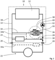
- FIG. 1 a schematic representation of a heating system with a heater and the Figures 2 to 4 the device according to the invention in different steps for removing a valve.
- a heating device 10 is shown schematically, which has a heat generator 12 for heating a heating fluid.
- a heating device 10 is intended to heat and provide a heating fluid or domestic water or both.
- the heating fluid or the domestic water can be heated in the flow and/or fed to a storage tank.
- a heat generator 12 is a device with which heat energy can be transferred to the heating fluid or the domestic water. Gas or oil burners, for example, or heat exchangers that are part of a district heating system, a solar heating system, a heat pump or the like are suitable for this purpose.
- the heating device 10 has a supply line 14 for delivering the heating fluid and a return line 16 for receiving the heating fluid.
- the supply line 14 and the return line 16 are led to the edge of a housing 18 enclosing the heating device 10 and have connections 20 there, via which they can be connected to a heating system 22.
- the heating system 22 is only shown schematically here and can be made up of various radiators, underfloor heating, storage tanks and the like. As a rule, these components each have control units via which their filling and flow can be adjusted.
- an additional heat exchanger 24 is housed in the heating device 10, via which, for example, domestic water can be heated.
- the heat exchanger 24 is connected to the flow line 14 with its inlet 26. Its outlet 28 is connected to the return line 16 via a three-way valve 30.
- the three-way valve 30 can be used to set the heating fluid to flow via the supply line 14 into the heating system 22 and from there back to the heater 10 via the return line 16, or to direct the heating fluid through the heat exchanger 24.
- mixed forms are also possible.
- a pump 32 is provided to drive the heating fluid.
- the pump 32 is located in the return line 16 within the housing 18 of the heater 10. In other designs, it is also possible to arrange the pump 32 in the feed line 14. It is also conceivable to install the pump 32 outside the housing 18.
- a bypass line 34 is arranged between the flow line 14 and the return line 16.
- the bypass 34 connects the flow line 14 to the return line 16 so that under certain conditions heating fluid can flow from the flow line 14 to the return line 16.
- a valve 36 is provided to influence the flow of the heating fluid.
- bypass line 34 is arranged inside the heater 10.
- bypass line 34a can also be arranged outside the housing 18 (dashed line in Figure 1 ).
- bypass line 34b is connected to the line of the outlet 28 and thus indirectly to the flow line 14 (dashed line in Figure 1 ).
- the valve is accommodated by a device 38.
- the device 38 has a sliding sleeve 40 which covers the valve 36 and secures it in its position.
- a sliding sleeve 40 is understood to be a sliding cover part or a housing part that can be moved in its position relative to other housing parts. It can be made of plastic or metal. In the exemplary embodiment, the sliding sleeve 40 has a wooden cylindrical shape.
- the sliding sleeve 40 can be moved to at least one closed position 42 ( Figure 2 ) and into an open position 44 ( Figures 3 and 4 ). In the open position 44, the valve 36 can be removed. It can then be checked, cleaned or replaced.
- FIG 3 the open position 44 is shown.
- the valve 36 is located in a recess 48 of the device 38. To remove it from this recess 48, it is moved analogously to the direction for opening the sliding sleeve 44 in the Figure 3 to the left. In the embodiment, this is an axial movement. Then it can be removed radially from the device 38. This is indicated with the arrow 50 and shown in the Figure 4 .
- bypass line has an interruption 52.
- This interruption 52 can accommodate the valve 36, which can then be covered and secured via the sliding sleeve 40.
- valve 36 is reinserted into the interruption 52 in reverse order and covered and secured with the sliding sleeve 40 after its axial displacement to the right.
- the device 38 has a radial stop 54 in the area of the recess 48.
- the valve is inserted radially into the interruption 52 until it hits the radial stop 54 and is then pushed axially into the recess 48. It is then secured and covered by axial displacement, to the right in the figures.
- the device 38 has seals 55 in the areas next to the interruption 52.
- these are O-ring seals.
- more complex seals with an H-cross section or seals with soft lips can also be used. It is advantageous if the seals 55 are inserted in such a way that they are directly assigned to the device 38 and are part of the device 38.
- the seals seal the entire receiving area in a fluid-tight manner when the sliding sleeve 40 is in the closed position 44.
- the sliding sleeve 40 has an expanding area 56. This allows it to be moved along the bypass line 34, with sufficient space being provided to accommodate the valve 36 by the expanded area 56.
- the expanding area is shown as a step in the exemplary embodiment. However, it can also be provided with bevels 57 (dashed in Figure 2 ) can be realized.
- the valve 36 has a housing 58 that widens on one side.
- the extension 60 of the housing 58 is dimensioned such that the valve 36 can only be inserted into the recess 48 with the side opposite the extension 60. This ensures that the valve 36 is always inserted in the correct position.
- the extension 60 can be implemented by a correspondingly shaped, flared housing 58. It is also possible to provide separate additional rings or structures.
- the extensions can be designed so that they rest against an inner area of the sliding sleeve 40, for example on the bevels 57, and be centered via the sliding sleeve 40. The sliding sleeve 40 can also press the valve 36 into the recess 48 in such a configuration.
- the valve 36 is a check valve 62. It is arranged in such a way that pressure equalization can take place from the supply line 14 to the return line 16.
- the check valve 62 blocks in the opposite direction.
- the check valve 62 has a fault-loaded valve member 64 which is pressed onto a valve seat 66 in its closed position.
- the pressure difference at which the check valve 62 opens is defined by the force with which a spring 68 presses the valve member 64 onto the valve seat 66.
- the check valve 62 can be designed in such a way that this force and thus the pressure difference at which the check valve 62 opens can be adjusted.
Landscapes
- Engineering & Computer Science (AREA)
- Physics & Mathematics (AREA)
- Thermal Sciences (AREA)
- Chemical & Material Sciences (AREA)
- Combustion & Propulsion (AREA)
- Mechanical Engineering (AREA)
- General Engineering & Computer Science (AREA)
- Check Valves (AREA)
Description
- Die Erfindung betrifft ein Heizgerät mit einem Wärmeerzeuger zum Erwärmen eines Heizfluid, mit einer Vorlaufleitung zum Abgeben des Heizfluids und mit einer Rücklaufleitung zum Aufnehmen des Heizfluids sowie mit einer Bypassleitung, die die Rücklaufleitung mit der Vorlaufleitung verbindet und mit einem Ventil in der Bypassleitung.
- Es ist bekannt (
WO 2017/093229 A1 ), Heizgeräte, die mit ihrer Vorlaufleitung und mit ihrer Rücklaufleitung an ein Heizungssystem angeschlossen werden, mit einer Bypassleitung zwischen der Vorlaufleitung und der Rücklaufleitung auszustatten. Damit kann verhindert werden, dass sich ungewollt ein Druck in der Vorlaufleitung aufbaut, wenn alle Durchgänge im Heizungssystem geschlossen oder zumindest stark gedrosselt sind. - Ein erfindungsgemäßes Heizgerät mit einem Wärmeerzeuger zum Erwärmen eines Heizfluids, einer Vorlaufleitung zum Abgeben des Heizfluids und einer Rücklaufleitung zum Aufnehmen des Heizfluids, mit einer Bypassleitung, die die Rücklaufleitung mit der Vorlaufleitung verbindet und mit einem Ventil in der Bypassleitung ist gekennzeichnet durch eine Einrichtung mittels der das Ventil von einer Schiebemuffe abdeckbar und mittels der Schiebemuffe sicherbar ist. Dadurch ist erreicht, dass das Ventil einfach austauschbar ist. Bei entsprechender Ausgestaltung der Schiebemuffe ist das Ventil auch werkzeuglos austauschbar. Wird eine separate Bypassleitung genutzt, kann, im Falle eines Stauens der Heizfluids, wenn im Heizsystem sämtliche Durchgänge gedrosselt sind, schnell und zuverlässig ein innerer Kreislauf aufgebaut werden, was einer Überhitzung des Wärmeerzeugers entgegenwirkt.
- Durch die in den Unteransprüchen aufgeführten Merkmale sind vorteilhafte Weiterbildungen des erfindungsgemäßen Heizgeräts möglich. So ist es besonders günstig, wenn die Schiebemuffe in mindestens eine geschlossene Stellung und mindestens eine geöffnete Stellung bringbar ist und in der geöffneten Stellung das Ventil austauschbar ist.
- In besonders einfacher Ausgestaltung weist die Bypassleitung eine Unterbrechung auf, die das Ventil aufzunehmen vermag und die durch die Schiebemuffe abdeckbar ist. Die Bypassleitung ist somit faktisch zweigeteilt.
- Ein einfaches und lagesicheres Einsetzen des Ventils wird erreicht, wenn die Bypassleitung im Bereich der Unterbrechung einen radialen Anschlag aufweist. Dieser radiale Anschlag ist im bevorzugten Fall einseitig angebracht.
- Um zu verhindern, dass das Heizfluid austritt, kann die Bypassleitung in Bereichen neben der Unterbrechung Dichtungen aufweisen.
- Eine einfache Ausführungsform ist gegeben, wenn die Schiebemuffe einen sich erweiternden Bereich aufweist.
- Ein lagesicheres Einsetzen des Ventils wird erreicht, wenn das Ventil ein sich einseitig erweiterndes Gehäuse aufweist.
- In einer vorteilhaften Ausgestaltung ist das Ventil ein Rückschlagventil. Damit kann ermöglicht werden, dass Heizfluid in der Bypassleitung von der Vorlaufleitung zur Rücklaufleitung fließen kann, der Weg zurück jedoch versperrt ist. Über den Öffnungsdruck des Rückschlagventils kann definiert werden, ab welcher Druckdifferenz das Rückschlagventil öffnet und das Heizungssystem entlastet.
- In der Zeichnung ist ein erfindungsgemäßes Heizgerät sowie eine erfindungsgemäße Einrichtung dargestellt und in der nachfolgenden Beschreibung näher erläutert. Es zeigen die
Figur 1 eine schematische Darstellung eines Heizungssystems mit einem Heizgerät und dieFiguren 2 bis 4 die erfindungsgemäße Einrichtung in unterschiedlichen Schritten zum Entnehmen eines Ventils. - In
Figur 1 ist schematisch ein Heizgerät 10 dargestellt, das einen Wärmeerzeuger 12 zum Erwärmen eines Heizfluids aufweist. Ein solches Heizgerät 10 ist dazu vorgesehen, ein Heizfluid oder Brauchwasser oder auch beides zu erwärmen und bereitzustellen. Dazu kann das Heizfluid oder das Brauchwasser im Durchlauf erhitzt und/oder einem Speicher zugeführt werden. Ein Wärmeerzeuger 12 ist dabei eine Vorrichtung, mit der Wärmeenergie auf das Heizfluid oder das Brauchwasser übertragen werden kann. Hierzu eignen sich beispielsweise Gas- oder Ölbrenner oder auch Wärmeübertrager, die Teil einer Fernwärmeheizung, einer Solarheizung, einer Wärmepumpe oder dergleichen sind. - Das Heizgerät 10 weist eine Vorlaufleitung 14 zum Abgeben des Heizfluids sowie eine Rücklaufleitung 16 zum Aufnehmen des Heizfluids auf. Die Vorlaufleitung 14 sowie die Rücklaufleitung 16 sind bis an den Rand eines das Heizgerät 10 einschließenden Gehäuses 18 geführt und weisen dort Anschlüsse 20 auf, über die sie mit einem Heizungssystem 22 verbindbar sind. Das Heizungssystem 22 ist hier nur schematisch dargestellt und kann aus verschiedenen Radiatoren, Fußbodenheizungen, Speicher und dergleichen aufgebaut sein. In der Regel weisen diese Komponenten jeweils Regeleinheiten auf, über die deren Befüllung und Durchlauf eingestellt werden kann.
- Im Ausführungsbeispiel ist im Heizgerät 10 ein zusätzlicher Wärmetauscher 24 untergebracht, über den beispielsweise Brauchwasser erwärmt werden kann. Der Wärmetauscher 24 ist mit seinem Eingang 26 an die Vorlaufleitung 14 angeschlossen. Sein Ausgang 28 ist über ein Dreiwegeventile 30 mit dem Rücklauf 16 verbunden.
- Über das Dreiwegeventile 30 kann eingestellt werden, dass das Heizfluid über die Vorlaufleitung 14 in das Heizungssystem 22 und von dort über die Rücklaufleitung 16 wieder zum Heizgerät 10 fließt oder dass das Heizfluid durch den Wärmetauscher 24 geleitet wird. Je nach Ausgestaltung des Dreiwegeventils 30 sind auch Mischformen möglich.
- Um das Heizfluid anzutreiben ist eine Pumpe 32 vorgesehen. Im Ausführungsbeispiel sitzt die Pumpe 32 in der Rücklaufleitung 16 innerhalb des Gehäuses 18 des Heizgeräts 10. Bei anderen Aufbauten ist es auch möglich, die Pumpe 32 in der Vorlaufleitung 14 anzuordnen. Es ist ferner denkbar, die Pumpe 32 außerhalb des Gehäuses 18 zu verbauen.
- Zwischen der Vorlaufleitung 14 und der Rücklaufleitung 16 ist eine Bypassleitung 34 angeordnet. Der Bypass 34 verbindet die Vorlaufleitung 14 mit der Rücklaufleitung 16 so, dass unter bestimmten Bedingungen Heizfluid von der Vorlaufleitung 14 zu der Rücklaufleitung 16 fließen kann. Um den Fluss des Heizfluids zu beeinflussen ist ein Ventil 36 vorgesehen.
- Im Ausführungsbeispiel ist die Bypassleitung 34 innerhalb des Heizgeräts 10 angeordnet. In einer alternativen Ausführungsform kann die Bypassleitung 34a auch außerhalb des Gehäuses 18 angeordnet sein (gestrichelte Linie in
Figur 1 ). Ferner ist in einer weiteren Ausführungsform die Bypassleitung 34b an die Leitung des Ausgangs 28 und damit indirekt an die Vorlaufleitung 14 angeschlossen (gestrichelte Linie inFigur 1 ). - Erfindungsgemäß ist das Ventil von einer Einrichtung 38 aufgenommen. Die Einrichtung 38 weist eine Schiebemuffe 40 auf, die das Ventil 36 abdeckt und in seiner Lage sichert.
- Unter einer Schiebemuffe 40 ist ein verschiebbares Abdeckteil oder ein Gehäuseteil zu verstehen, das in seiner Lage gegenüber weiteren Gehäuseteilen verschiebbar ist. Sie kann aus Kunststoff bestehen oder aus Metall gefertigt sein. Im Ausführungsbeispiel ist die Schiebemuffe 40 von holzylindrischer Form.
- Die Schiebemuffe 40 lässt sich zumindest in eine geschlossene Stellung 42 (
Figur 2 ) und in eine offene Stellung 44 (Figuren 3 und4 ) verschieben. In der offenen Stellung 44 kann das Ventil 36 entnommen werden. Es kann dann kontrolliert, gereinigt oder auch ausgetauscht werden. - In den
Figuren 2 bis 4 ist eine solche Entnahme in drei Schritten dargestellt. Gleiche Teile sind mit gleichen Bezugszeichen belegt. InFigur 2 ist die Schiebemuffe 40 in geschlossener Stellung 42 dargestellt. Mit dem Doppelpfeil 44 ist gezeigt, wie sich die Schiebemuffe 40 verschieben lässt. Von der geschlossenen Stellung 42, in der das Ventil 36 gesichert ist, wird zum Austausch des Ventils 36 die Schiebemuffe 40 entsprechend dem Doppelpfeil 44 in derFigur 2 nach links verschoben. Damit öffnet sich die Einrichtung 38. - In
Figur 3 ist die geöffnete Stellung 44 dargestellt. Das Ventil 36 sitzt in einer Vertiefung 48 der Einrichtung 38. Um es aus dieser Vertiefung 48 herauszunehmen wird es analog der Richtung zum Öffnen der Schiebemuffe 44 in derFigur 3 nach links bewegt. Im Ausführungsbeispiel ist das eine axiale Bewegung. Dann kann es radial aus der Einrichtung 38 entnommen werden. Dies ist angedeutet mit dem Pfeil 50 und dargestellt in derFigur 4 . - In der
Figur 4 ist zu erkennen, dass die Bypassleitung eine Unterbrechung 52 aufweist. Diese Unterbrechung 52 kann das Ventil 36 aufnehmen, das dann über die Schiebemuffe 40 abgedeckt und gesichert werden kann. - Das Ventil 36 wird in umgekehrter Reihenfolge wieder in die Unterbrechung 52 eingesetzt und mit der Schiebemuffe 40 nach deren axialem Verschieben nach rechts abgedeckt und gesichert.
- Um das Einsetzen des Ventils 36 zu vereinfachen, weist die Einrichtung 38 im Bereich der Vertiefung 48 einen radialen Anschlag 54 auf. Beim Einsetzen des Ventils 36 wird das Ventil in die Unterbrechung 52 radial eingesetzt, bis dieses am radialen Anschlag 54 anschlägt und wird dann axial in die Vertiefung 48 geschoben. Danach wird durch axiales Verschieben, in den Figuren nach rechts, gesichert und abgedeckt.
- Die Einrichtung 38 weist in den Bereichen neben der Unterbrechung 52 Dichtungen 55 auf. Im Ausführungsbeispiel sind das O-Ringdichtungen. Es können aber auch aufwendigere Dichtungen mit einem H-Querschnitt oder Dichtungen mit weichen Lippen eingesetzt sein. Von Vorteil ist es, wenn die Dichtungen 55 so eingebracht sind, dass sie der Einrichtung 38 direkt zugeordnet sind und Teil der Einrichtung 38 sind. Die Dichtungen verschließen den gesamten Aufnahmebereich, wenn die Schiebemuffe 40 in der geschlossenen Stellung 44 ist, fluiddicht.
- Um die Unterbrechung 52 und damit das Ventil 36 optimal aufnehmen und abdecken zu können, weist die Schiebemuffe 40 einen sich erweiternden Bereich 56 auf. Damit kann ein Verschieben entlang der Bypassleitung 34 erfolgen, wobei genügend Platz zur Aufnahme des Ventils 36 durch den erweiterten Bereich 56 bereitgestellt ist. Der sich erweiternde Bereich ist im Ausführungsbeispiel als Stufe dargestellt. Er kann aber ebenso mit Schrägen 57 (gestrichelt in
Figur 2 ) realisiert werden. - Das Ventil 36 weist ein sich einseitig erweiterndes Gehäuse 58 auf. Die Erweiterung 60 des Gehäuses 58 ist so bemessen, dass das Ventil 36 nur mit der der Erweiterung 60 gegenüberliegenden Seite in die Vertiefung 48 eingeschoben werden kann. Damit ist sichergestellt, dass das Ventil 36 immer lagerichtig eingesetzt wird. Die Erweiterung 60 kann zum einen durch ein entsprechend geformtes, ausgestelltes Gehäuse 58 realisiert sein. Es ist auch möglich separate zusätzliche Ringe oder Aufbauten vorzusehen. Die Erweiterungen können so ausgeführt sein, dass sie sich an einen inneren Bereich der Schiebemuffe 40 anlehnen, beispielsweise an den Schrägen 57, und über die Schiebemuffe 40 zentriert werden. Die Schiebemuffe 40 kann das Ventil 36 in einer solchen Konstellation auch in die Vertiefung 48 einpressen.
- Im Ausführungsbeispiel ist das Ventil 36 ein Rückschlagventil 62. Es ist so angeordnet, dass ein Druckausgleich von der Vorlaufleitung 14 zur Rücklaufleitung 16 stattfinden kann. In der entgegengesetzten Richtung sperrt das Rückschlagventil 62. Im Ausführungsbeispiel weist das Rückschlagventil 62 ein fehlerbelastetes Ventilglied 64 auf, das in seiner geschlossenen Position auf einen Ventilsitz 66 gedrückt ist. Über die Kraft mit der eine Feder 68 das Ventilglied 64 auf den Ventilsitz 66 drückt, ist die Druckdifferenz definiert, bei der das Rückschlagventil 62 öffnet. In anderen Ausführungsformen kann das Rückschlagventil 62 so ausgeführt sein, dass diese Kraft und damit die Druckdifferenz, bei der das Rückschlagventil 62 öffnet, einstellbar ist.
Claims (8)
- Heizgerät (10) mit einem Wärmeerzeuger (12) zum Erwärmen eines Heizfluids, einer Vorlaufleitung (14) zum Abgeben des Heizfluids und einer Rücklaufleitung (16) zum Aufnehmen des Heizfluids, mit einer Bypassleitung (34, 34a, 34b), die die Rücklaufleitung (16) mit der Vorlaufleitung (14) verbindet und mit einem Ventil (36) in der Bypassleitung (34), gekennzeichnet durch eine Einrichtung (38) mittels der das Ventil (36) von einer Schiebemuffe (40) abdeckbar und mittels der Schiebmuffe (40) sicherbar ist.
- Heizgerät (10) nach Anspruch 1, dadurch gekennzeichnet, dass die Schiebemuffe (40) in mindestens eine geschlossene Stellung (42) und mindestens eine geöffnete Stellung (44) bringbar ist und dass in der geöffneten Stellung (42) das Ventil (36) austauschbar ist.
- Heizgerät (10) nach einem der vorhergehenden Ansprüche, dadurch gekennzeichnet, dass die Bypassleitung (34) eine Unterbrechung (52) aufweist, die das Ventil (36) aufzunehmen vermag und die durch die Schiebmuffe (40) abdeckbar ist.
- Heizgerät (10) nach einem der vorhergehenden Ansprüche, dadurch gekennzeichnet, dass die Bypassleitung (34) im Bereich der Unterbrechung (52) einen insbesondere einseitigen radialen Anschlag (54) aufweist.
- Heizgerät (10) nach einem der vorhergehenden Ansprüche, dadurch gekennzeichnet, dass die Bypassleitung (34) in Bereichen neben der Unterbrechung (52) Dichtungen (55) aufweist.
- Heizgerät (10) nach einem der vorhergehenden Ansprüche, dadurch gekennzeichnet, dass die Schiebemuffe (40) einen sich erweiternden Bereich (56) aufweist.
- Heizgerät (10) nach einem der vorhergehenden Ansprüche, dadurch gekennzeichnet, dass das Ventil (36) ein sich einseitig erweiterndes Gehäuse (58) aufweist.
- Heizgerät (10) nach einem der vorhergehenden Ansprüche, dadurch gekennzeichnet, dass das Ventil (36) ein Rückschlagventil (62) ist.
Applications Claiming Priority (1)
| Application Number | Priority Date | Filing Date | Title |
|---|---|---|---|
| DE102021208121.5A DE102021208121A1 (de) | 2021-07-28 | 2021-07-28 | Heizgerät mit einer Bypassleitung sowie Einrichtung für ein Heizgerät |
Publications (2)
| Publication Number | Publication Date |
|---|---|
| EP4124808A1 EP4124808A1 (de) | 2023-02-01 |
| EP4124808B1 true EP4124808B1 (de) | 2024-09-11 |
Family
ID=82547083
Family Applications (1)
| Application Number | Title | Priority Date | Filing Date |
|---|---|---|---|
| EP22183069.8A Active EP4124808B1 (de) | 2021-07-28 | 2022-07-05 | Heizgerät mit einer bypassleitung sowie einrichtung für ein heizgerät |
Country Status (3)
| Country | Link |
|---|---|
| EP (1) | EP4124808B1 (de) |
| CN (1) | CN115682431A (de) |
| DE (1) | DE102021208121A1 (de) |
Families Citing this family (1)
| Publication number | Priority date | Publication date | Assignee | Title |
|---|---|---|---|---|
| US20260020497A1 (en) * | 2022-07-13 | 2026-01-15 | National Thermovoltaics Inc. | Thermoelectric generator apparatuses and systems |
Family Cites Families (7)
| Publication number | Priority date | Publication date | Assignee | Title |
|---|---|---|---|---|
| DE3320623A1 (de) * | 1983-06-08 | 1984-12-13 | Günter 4722 Ennigerloh Battert | Filtereinrichtung zur dachentwaesserung |
| DE4407371A1 (de) | 1994-03-05 | 1995-09-07 | Bosch Gmbh Robert | Heizgerät für Raumheizung und Brauchwassererwärmung |
| DE59802135D1 (de) * | 1997-07-04 | 2001-12-20 | Bayerische Motoren Werke Ag | Ventilvorrichtung für einen im nebenstrom angeordneten wärmetauscher in einem kühlkreislauf, insbesondere einer brennkraftmaschine |
| ITMI20040314A1 (it) * | 2004-02-24 | 2004-05-24 | Gv Stamperie S P A | Dispositivo per la gestione di flussi in gruppi di riscaldamento combinato di acqua sanitaria e di ambienti domestici e gruppo caldaia per il riscaldamento combinato di acqua sanitaria e di ambienti domestici |
| PL1884720T3 (pl) * | 2006-07-28 | 2016-08-31 | Grundfos Management As | Jednostka konstrukcyjna dla kompaktowej instalacji grzewczej |
| AT509211B1 (de) * | 2010-03-09 | 2011-07-15 | Florian Dr Pickl | Platzsparende entlüftung von geschlossenen, in überdruck gegen die atmosphäre stehenden rohrsystemen mit zentraler, ortsunabhängiger entlüftungsstelle |
| PT109011A (pt) * | 2015-12-03 | 2017-06-05 | Bosch Termotecnologia Sa | Dispositivo para a produção de água quente |
-
2021
- 2021-07-28 DE DE102021208121.5A patent/DE102021208121A1/de not_active Withdrawn
-
2022
- 2022-07-05 EP EP22183069.8A patent/EP4124808B1/de active Active
- 2022-07-28 CN CN202210897288.1A patent/CN115682431A/zh active Pending
Also Published As
| Publication number | Publication date |
|---|---|
| EP4124808A1 (de) | 2023-02-01 |
| DE102021208121A1 (de) | 2023-02-02 |
| CN115682431A (zh) | 2023-02-03 |
Similar Documents
| Publication | Publication Date | Title |
|---|---|---|
| DE60313363T2 (de) | Steuerventil mit verbesserter dichtigkeit für einen flüssigkeitsströmungskreis | |
| DE2914473A1 (de) | Filter | |
| DE2061821A1 (de) | Vorrichtung zum Anschluß hydraulischer Gerate | |
| EP1198682A1 (de) | Schnellkupplung für das öffnen eines ventils | |
| EP2054132A1 (de) | Ölfilteranordnung und filterelement hierfür | |
| DE69707237T2 (de) | Heizkörperventil | |
| DE102011003991A1 (de) | Nockenwellenversteller mit einem Druckspeicher | |
| EP4382814A1 (de) | Strömungseinrichtung zum nachrüsten einer heizungsanlage und eine heizungsanlage | |
| EP4124808A1 (de) | Heizgerät mit einer bypassleitung sowie einrichtung für ein heizgerät | |
| EP2881635B1 (de) | Ventileinheit für einen Heizkreisverteiler und Heizkreisverteiler | |
| EP2626526B1 (de) | Ventileinrichtung | |
| DE4418737C2 (de) | Anordnung zur Warmwasserbereitung mit Satelitenspeicher und Rückschlagventil | |
| WO2008052782A1 (de) | Rückschlagventil | |
| DE102014115903A1 (de) | Hydraulikventil und Schwenkmotorversteller | |
| EP1741936A1 (de) | Fördermengenregelventil für liquide Medien | |
| DE102005044845A1 (de) | Trinkwassererwärmungsanlage | |
| EP3511634B1 (de) | Anschluss-set | |
| DE102012208808A1 (de) | Steuerventil zur Steuerung von Druckmittelströmen eines Nockenwellenverstellers | |
| DE102011081018B3 (de) | Filterstopfen für Schlauchleitungen | |
| DE102011111771A1 (de) | Fluidverteiler | |
| DE102021101145A1 (de) | Verteilerventil für eine Kaffeemaschine, Kaffeemaschine mit einem solchen Verteilerventil, und Verfahren zum Verteilen von Medien auf Verbrauchsfunktionalitäten einer Kaffeemaschine | |
| DE102013224244A1 (de) | Hydraulikkreislauf | |
| DE29812384U1 (de) | Als Schwerkraftbremse ausgebildetes Rohrleitungsventil | |
| WO2009077408A2 (de) | Zerstäubungsvorrichtung für einen brenner zur verbrennung von vorzuwärmenden brennstoffen | |
| EP2868985B1 (de) | Trinkwassererwärmungsanlage und Verfahren zum Betreiben einer Trinkwassererwärmungsanlage |
Legal Events
| Date | Code | Title | Description |
|---|---|---|---|
| PUAI | Public reference made under article 153(3) epc to a published international application that has entered the european phase |
Free format text: ORIGINAL CODE: 0009012 |
|
| STAA | Information on the status of an ep patent application or granted ep patent |
Free format text: STATUS: THE APPLICATION HAS BEEN PUBLISHED |
|
| AK | Designated contracting states |
Kind code of ref document: A1 Designated state(s): AL AT BE BG CH CY CZ DE DK EE ES FI FR GB GR HR HU IE IS IT LI LT LU LV MC MK MT NL NO PL PT RO RS SE SI SK SM TR |
|
| STAA | Information on the status of an ep patent application or granted ep patent |
Free format text: STATUS: REQUEST FOR EXAMINATION WAS MADE |
|
| 17P | Request for examination filed |
Effective date: 20230801 |
|
| RBV | Designated contracting states (corrected) |
Designated state(s): AL AT BE BG CH CY CZ DE DK EE ES FI FR GB GR HR HU IE IS IT LI LT LU LV MC MK MT NL NO PL PT RO RS SE SI SK SM TR |
|
| GRAP | Despatch of communication of intention to grant a patent |
Free format text: ORIGINAL CODE: EPIDOSNIGR1 |
|
| STAA | Information on the status of an ep patent application or granted ep patent |
Free format text: STATUS: GRANT OF PATENT IS INTENDED |
|
| INTG | Intention to grant announced |
Effective date: 20240416 |
|
| GRAS | Grant fee paid |
Free format text: ORIGINAL CODE: EPIDOSNIGR3 |
|
| GRAA | (expected) grant |
Free format text: ORIGINAL CODE: 0009210 |
|
| STAA | Information on the status of an ep patent application or granted ep patent |
Free format text: STATUS: THE PATENT HAS BEEN GRANTED |
|
| AK | Designated contracting states |
Kind code of ref document: B1 Designated state(s): AL AT BE BG CH CY CZ DE DK EE ES FI FR GB GR HR HU IE IS IT LI LT LU LV MC MK MT NL NO PL PT RO RS SE SI SK SM TR |
|
| REG | Reference to a national code |
Ref country code: GB Ref legal event code: FG4D Free format text: NOT ENGLISH |
|
| REG | Reference to a national code |
Ref country code: CH Ref legal event code: EP |
|
| REG | Reference to a national code |
Ref country code: DE Ref legal event code: R096 Ref document number: 502022001647 Country of ref document: DE |
|
| REG | Reference to a national code |
Ref country code: IE Ref legal event code: FG4D Free format text: LANGUAGE OF EP DOCUMENT: GERMAN |
|
| REG | Reference to a national code |
Ref country code: LT Ref legal event code: MG9D |
|
| PG25 | Lapsed in a contracting state [announced via postgrant information from national office to epo] |
Ref country code: NO Free format text: LAPSE BECAUSE OF FAILURE TO SUBMIT A TRANSLATION OF THE DESCRIPTION OR TO PAY THE FEE WITHIN THE PRESCRIBED TIME-LIMIT Effective date: 20241211 |
|
| REG | Reference to a national code |
Ref country code: NL Ref legal event code: MP Effective date: 20240911 |
|
| PG25 | Lapsed in a contracting state [announced via postgrant information from national office to epo] |
Ref country code: GR Free format text: LAPSE BECAUSE OF FAILURE TO SUBMIT A TRANSLATION OF THE DESCRIPTION OR TO PAY THE FEE WITHIN THE PRESCRIBED TIME-LIMIT Effective date: 20241212 Ref country code: FI Free format text: LAPSE BECAUSE OF FAILURE TO SUBMIT A TRANSLATION OF THE DESCRIPTION OR TO PAY THE FEE WITHIN THE PRESCRIBED TIME-LIMIT Effective date: 20240911 |
|
| PG25 | Lapsed in a contracting state [announced via postgrant information from national office to epo] |
Ref country code: BG Free format text: LAPSE BECAUSE OF FAILURE TO SUBMIT A TRANSLATION OF THE DESCRIPTION OR TO PAY THE FEE WITHIN THE PRESCRIBED TIME-LIMIT Effective date: 20240911 |
|
| PG25 | Lapsed in a contracting state [announced via postgrant information from national office to epo] |
Ref country code: LV Free format text: LAPSE BECAUSE OF FAILURE TO SUBMIT A TRANSLATION OF THE DESCRIPTION OR TO PAY THE FEE WITHIN THE PRESCRIBED TIME-LIMIT Effective date: 20240911 |
|
| PG25 | Lapsed in a contracting state [announced via postgrant information from national office to epo] |
Ref country code: HR Free format text: LAPSE BECAUSE OF FAILURE TO SUBMIT A TRANSLATION OF THE DESCRIPTION OR TO PAY THE FEE WITHIN THE PRESCRIBED TIME-LIMIT Effective date: 20240911 |
|
| PG25 | Lapsed in a contracting state [announced via postgrant information from national office to epo] |
Ref country code: ES Free format text: LAPSE BECAUSE OF FAILURE TO SUBMIT A TRANSLATION OF THE DESCRIPTION OR TO PAY THE FEE WITHIN THE PRESCRIBED TIME-LIMIT Effective date: 20240911 Ref country code: RS Free format text: LAPSE BECAUSE OF FAILURE TO SUBMIT A TRANSLATION OF THE DESCRIPTION OR TO PAY THE FEE WITHIN THE PRESCRIBED TIME-LIMIT Effective date: 20241211 |
|
| PG25 | Lapsed in a contracting state [announced via postgrant information from national office to epo] |
Ref country code: RS Free format text: LAPSE BECAUSE OF FAILURE TO SUBMIT A TRANSLATION OF THE DESCRIPTION OR TO PAY THE FEE WITHIN THE PRESCRIBED TIME-LIMIT Effective date: 20241211 Ref country code: NO Free format text: LAPSE BECAUSE OF FAILURE TO SUBMIT A TRANSLATION OF THE DESCRIPTION OR TO PAY THE FEE WITHIN THE PRESCRIBED TIME-LIMIT Effective date: 20241211 Ref country code: LV Free format text: LAPSE BECAUSE OF FAILURE TO SUBMIT A TRANSLATION OF THE DESCRIPTION OR TO PAY THE FEE WITHIN THE PRESCRIBED TIME-LIMIT Effective date: 20240911 Ref country code: HR Free format text: LAPSE BECAUSE OF FAILURE TO SUBMIT A TRANSLATION OF THE DESCRIPTION OR TO PAY THE FEE WITHIN THE PRESCRIBED TIME-LIMIT Effective date: 20240911 Ref country code: GR Free format text: LAPSE BECAUSE OF FAILURE TO SUBMIT A TRANSLATION OF THE DESCRIPTION OR TO PAY THE FEE WITHIN THE PRESCRIBED TIME-LIMIT Effective date: 20241212 Ref country code: FI Free format text: LAPSE BECAUSE OF FAILURE TO SUBMIT A TRANSLATION OF THE DESCRIPTION OR TO PAY THE FEE WITHIN THE PRESCRIBED TIME-LIMIT Effective date: 20240911 Ref country code: ES Free format text: LAPSE BECAUSE OF FAILURE TO SUBMIT A TRANSLATION OF THE DESCRIPTION OR TO PAY THE FEE WITHIN THE PRESCRIBED TIME-LIMIT Effective date: 20240911 Ref country code: BG Free format text: LAPSE BECAUSE OF FAILURE TO SUBMIT A TRANSLATION OF THE DESCRIPTION OR TO PAY THE FEE WITHIN THE PRESCRIBED TIME-LIMIT Effective date: 20240911 |
|
| PG25 | Lapsed in a contracting state [announced via postgrant information from national office to epo] |
Ref country code: NL Free format text: LAPSE BECAUSE OF FAILURE TO SUBMIT A TRANSLATION OF THE DESCRIPTION OR TO PAY THE FEE WITHIN THE PRESCRIBED TIME-LIMIT Effective date: 20240911 |
|
| PG25 | Lapsed in a contracting state [announced via postgrant information from national office to epo] |
Ref country code: IS Free format text: LAPSE BECAUSE OF FAILURE TO SUBMIT A TRANSLATION OF THE DESCRIPTION OR TO PAY THE FEE WITHIN THE PRESCRIBED TIME-LIMIT Effective date: 20250111 Ref country code: PT Free format text: LAPSE BECAUSE OF FAILURE TO SUBMIT A TRANSLATION OF THE DESCRIPTION OR TO PAY THE FEE WITHIN THE PRESCRIBED TIME-LIMIT Effective date: 20250113 |
|
| PG25 | Lapsed in a contracting state [announced via postgrant information from national office to epo] |
Ref country code: SM Free format text: LAPSE BECAUSE OF FAILURE TO SUBMIT A TRANSLATION OF THE DESCRIPTION OR TO PAY THE FEE WITHIN THE PRESCRIBED TIME-LIMIT Effective date: 20240911 Ref country code: RO Free format text: LAPSE BECAUSE OF FAILURE TO SUBMIT A TRANSLATION OF THE DESCRIPTION OR TO PAY THE FEE WITHIN THE PRESCRIBED TIME-LIMIT Effective date: 20240911 |
|
| PG25 | Lapsed in a contracting state [announced via postgrant information from national office to epo] |
Ref country code: EE Free format text: LAPSE BECAUSE OF FAILURE TO SUBMIT A TRANSLATION OF THE DESCRIPTION OR TO PAY THE FEE WITHIN THE PRESCRIBED TIME-LIMIT Effective date: 20240911 |
|
| PG25 | Lapsed in a contracting state [announced via postgrant information from national office to epo] |
Ref country code: CZ Free format text: LAPSE BECAUSE OF FAILURE TO SUBMIT A TRANSLATION OF THE DESCRIPTION OR TO PAY THE FEE WITHIN THE PRESCRIBED TIME-LIMIT Effective date: 20240911 Ref country code: PL Free format text: LAPSE BECAUSE OF FAILURE TO SUBMIT A TRANSLATION OF THE DESCRIPTION OR TO PAY THE FEE WITHIN THE PRESCRIBED TIME-LIMIT Effective date: 20240911 |
|
| PG25 | Lapsed in a contracting state [announced via postgrant information from national office to epo] |
Ref country code: SK Free format text: LAPSE BECAUSE OF FAILURE TO SUBMIT A TRANSLATION OF THE DESCRIPTION OR TO PAY THE FEE WITHIN THE PRESCRIBED TIME-LIMIT Effective date: 20240911 Ref country code: IT Free format text: LAPSE BECAUSE OF FAILURE TO SUBMIT A TRANSLATION OF THE DESCRIPTION OR TO PAY THE FEE WITHIN THE PRESCRIBED TIME-LIMIT Effective date: 20240911 |
|
| REG | Reference to a national code |
Ref country code: DE Ref legal event code: R097 Ref document number: 502022001647 Country of ref document: DE |
|
| PG25 | Lapsed in a contracting state [announced via postgrant information from national office to epo] |
Ref country code: DK Free format text: LAPSE BECAUSE OF FAILURE TO SUBMIT A TRANSLATION OF THE DESCRIPTION OR TO PAY THE FEE WITHIN THE PRESCRIBED TIME-LIMIT Effective date: 20240911 |
|
| PLBE | No opposition filed within time limit |
Free format text: ORIGINAL CODE: 0009261 |
|
| STAA | Information on the status of an ep patent application or granted ep patent |
Free format text: STATUS: NO OPPOSITION FILED WITHIN TIME LIMIT |
|
| 26N | No opposition filed |
Effective date: 20250612 |
|
| PG25 | Lapsed in a contracting state [announced via postgrant information from national office to epo] |
Ref country code: SE Free format text: LAPSE BECAUSE OF FAILURE TO SUBMIT A TRANSLATION OF THE DESCRIPTION OR TO PAY THE FEE WITHIN THE PRESCRIBED TIME-LIMIT Effective date: 20240911 |
|
| PGFP | Annual fee paid to national office [announced via postgrant information from national office to epo] |
Ref country code: DE Payment date: 20250924 Year of fee payment: 4 |
|
| PGFP | Annual fee paid to national office [announced via postgrant information from national office to epo] |
Ref country code: FR Payment date: 20250723 Year of fee payment: 4 Ref country code: AT Payment date: 20251020 Year of fee payment: 4 |
|
| REG | Reference to a national code |
Ref country code: CH Ref legal event code: H13 Free format text: ST27 STATUS EVENT CODE: U-0-0-H10-H13 (AS PROVIDED BY THE NATIONAL OFFICE) Effective date: 20260224 |
|
| PG25 | Lapsed in a contracting state [announced via postgrant information from national office to epo] |
Ref country code: LU Free format text: LAPSE BECAUSE OF NON-PAYMENT OF DUE FEES Effective date: 20250705 |
|
| REG | Reference to a national code |
Ref country code: BE Ref legal event code: MM Effective date: 20250731 |
|
| PG25 | Lapsed in a contracting state [announced via postgrant information from national office to epo] |
Ref country code: BE Free format text: LAPSE BECAUSE OF NON-PAYMENT OF DUE FEES Effective date: 20250731 |
|
| PG25 | Lapsed in a contracting state [announced via postgrant information from national office to epo] |
Ref country code: CH Free format text: LAPSE BECAUSE OF NON-PAYMENT OF DUE FEES Effective date: 20250731 |