EP4124517B1 - A windshield wiper cowl assembly with a flush-mounted inset hose connector - Google Patents
A windshield wiper cowl assembly with a flush-mounted inset hose connector Download PDFInfo
- Publication number
- EP4124517B1 EP4124517B1 EP21188874.8A EP21188874A EP4124517B1 EP 4124517 B1 EP4124517 B1 EP 4124517B1 EP 21188874 A EP21188874 A EP 21188874A EP 4124517 B1 EP4124517 B1 EP 4124517B1
- Authority
- EP
- European Patent Office
- Prior art keywords
- hose connector
- cowl
- assembly
- electrical
- cowl assembly
- Prior art date
- Legal status (The legal status is an assumption and is not a legal conclusion. Google has not performed a legal analysis and makes no representation as to the accuracy of the status listed.)
- Active
Links
Images


Classifications
-
- B—PERFORMING OPERATIONS; TRANSPORTING
- B60—VEHICLES IN GENERAL
- B60S—SERVICING, CLEANING, REPAIRING, SUPPORTING, LIFTING, OR MANOEUVRING OF VEHICLES, NOT OTHERWISE PROVIDED FOR
- B60S1/00—Cleaning of vehicles
- B60S1/02—Cleaning windscreens, windows or optical devices
- B60S1/04—Wipers or the like, e.g. scrapers
- B60S1/32—Wipers or the like, e.g. scrapers characterised by constructional features of wiper blade arms or blades
- B60S1/34—Wiper arms; Mountings therefor
- B60S1/3488—Means for mounting wiper arms onto the vehicle
- B60S1/349—Means for mounting the wiper bearing to the vehicle body
-
- B—PERFORMING OPERATIONS; TRANSPORTING
- B62—LAND VEHICLES FOR TRAVELLING OTHERWISE THAN ON RAILS
- B62D—MOTOR VEHICLES; TRAILERS
- B62D25/00—Superstructure or monocoque structure sub-units; Parts or details thereof not otherwise provided for
- B62D25/08—Front or rear portions
- B62D25/081—Cowls
-
- B—PERFORMING OPERATIONS; TRANSPORTING
- B60—VEHICLES IN GENERAL
- B60S—SERVICING, CLEANING, REPAIRING, SUPPORTING, LIFTING, OR MANOEUVRING OF VEHICLES, NOT OTHERWISE PROVIDED FOR
- B60S1/00—Cleaning of vehicles
- B60S1/02—Cleaning windscreens, windows or optical devices
- B60S1/04—Wipers or the like, e.g. scrapers
- B60S1/0475—Cleaning of wiper blades
- B60S1/0477—Arrangement for deicing or for removing debris from wiper blades
-
- B—PERFORMING OPERATIONS; TRANSPORTING
- B60—VEHICLES IN GENERAL
- B60S—SERVICING, CLEANING, REPAIRING, SUPPORTING, LIFTING, OR MANOEUVRING OF VEHICLES, NOT OTHERWISE PROVIDED FOR
- B60S1/00—Cleaning of vehicles
- B60S1/02—Cleaning windscreens, windows or optical devices
- B60S1/46—Cleaning windscreens, windows or optical devices using liquid; Windscreen washers
- B60S1/48—Liquid supply therefor
-
- B—PERFORMING OPERATIONS; TRANSPORTING
- B60—VEHICLES IN GENERAL
- B60S—SERVICING, CLEANING, REPAIRING, SUPPORTING, LIFTING, OR MANOEUVRING OF VEHICLES, NOT OTHERWISE PROVIDED FOR
- B60S1/00—Cleaning of vehicles
- B60S1/02—Cleaning windscreens, windows or optical devices
- B60S1/04—Wipers or the like, e.g. scrapers
- B60S1/0452—Position of the wipers relative to the vehicle
- B60S1/0458—Arrangement wherein the windscreen frame cooperates with the wipers
- B60S1/0463—Arrangement of the cowl
-
- B—PERFORMING OPERATIONS; TRANSPORTING
- B60—VEHICLES IN GENERAL
- B60S—SERVICING, CLEANING, REPAIRING, SUPPORTING, LIFTING, OR MANOEUVRING OF VEHICLES, NOT OTHERWISE PROVIDED FOR
- B60S1/00—Cleaning of vehicles
- B60S1/02—Cleaning windscreens, windows or optical devices
- B60S1/04—Wipers or the like, e.g. scrapers
- B60S1/32—Wipers or the like, e.g. scrapers characterised by constructional features of wiper blade arms or blades
- B60S1/38—Wiper blades
- B60S1/3803—Wiper blades heated wiper blades
- B60S1/3805—Wiper blades heated wiper blades electrically
Definitions
- a vehicle windshield wiper cowl assembly comprising a protective cowl panel adapted to be mounted on the bodywork of a vehicle at the lower end of the vehicle's windshield, the cowl panel having a shaft opening for the pivot shaft of a windshield wiper, the shaft opening having a circumferential border area with a front side and a back side, wherein the border area front side defines a circumferential bordering surface, and a hose connector having a back face and a front face, wherein the hose connector is set into the cowl panel's shaft opening so that the hose connector is bordered by the shaft opening's circumferential border area.
- Such a vehicle windshield wiper cowl assembly is known from document JP2010-012815A , cf. its Figs. 1 and 2 .
- This known cowl assembly comprises an outer cowl panel 17, an inner cowl panel 16 and an oval rubber grommet 40, which acts as a hose connector for two washer fluid hoses 35 and 38.
- the grommet 40 is set into a through-hole 16a of the inner cowl panel 16 and provides a watertight seal, which prevents water from entering the car body.
- the front face 41 b of the grommet 40 has a cup shape with a protruding circumferential sealing lip 47.
- the sealing lip 47 is in pressure contact with an inner surface 17b of the outer cowl panel 17, cf. Fig. 2 .
- the document EP 3 381 754 A1 discloses a further configuration for a vehicle windshield wiper cowl assembly as known in the art.
- this object is achieved with a vehicle windshield wiper cowl assembly according to claim 1.
- an assembly-line worker can easily and quickly connect a first washer fluid hose from below the cowl assembly, and a second washer fluid hose from above the cowl assembly.
- the present disclosure also relates to a motor vehicle comprising a cowl assembly as defined above.
- the present disclosure is concerned with improvements to windshield wiper cowl assemblies, which are used as parts of vehicles, such as motor vehicles.
- the main component of such cowl assemblies is a cowl panel.
- a cowl panel is mounted on the bodywork of a vehicle at the lower end of the vehicle's windshield. Its main purpose is to cover and protect the driving linkage of the one or more windshield wipers from dirt, rainwater, debris or the like.
- cowl panels have at least one shaft opening for the pivot shaft of a windshield wiper.
- cowl assemblies that are especially suited for use with nozzle windshield wipers, i.e. windshield wipers having integrated nozzles for the spraying of washer fluid.
- These particular cowl assemblies comprise means allowing the washer fluid, which is supplied from a reservoir in the vehicle's body, to cross the cowl panel to reach the nozzle windshield wiper.
- This type of cowl assembly may be referred to as a cowl assembly with washer fluid transit.
- the figures show three different variants of cowl assemblies with washer fluid transit, wherein the first two variants are embodiments of the present disclosure, and the third variant is for further illustration.
- front and back are understood to have the following meaning:
- front indicates that the corresponding element faces towards the outside of the vehicle when it is in an operational state and part of the vehicle.
- back indicates that the corresponding element faces towards the inside of the vehicle when it is in an operational state and part of the vehicle.
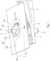
- a first embodiment 100 of a cowl assembly according to the present disclosure.
- Figs. 1 and 2 show the cowl assembly 100 together with a pivot shaft 2, a shaft supporting member 4, a washer fluid hose 6 and a hose clip 8.
- the pivot shaft 2 is made for pivoting a windshield wiper in a reciprocating manner. To that end, the head of a windshield wiper arm may be attached to the top end 10 of the pivot shaft 2. The base 12 of the pivot shaft 2 is received in the shaft supporting member 4.
- the washer fluid hose 6 is secured to the shaft supporting member 4 via the hose clip 8.
- the cowl assembly 100 comprises a protective cowl panel 102 and a hose connector 104.
- the protective cowl panel 102 is adapted to be mounted on the bodywork of a vehicle at the lower end of the vehicle's windshield.
- the cowl panel 102 has a shaft opening 106.
- the pivot shaft 2 extends through the shaft opening 106.
- the shaft opening 106 has a circumferential border area 108.
- a front side 110 of the border area 108 is visible in Fig.1
- a back side 112 of the border area 108 is visible in Fig. 2 .
- the front side 110 of the border are 108 defines a circumferential bordering surface 114.
- the back side 112 of the border area 108 comprises a circumferential collar 115.
- the hose connector 104 is set into the shaft opening 106 of the cowl panel 102. Accordingly, the hose connector 104 is bordered by the circumferential border area 108 of the shaft opening 106.
- a front face 116 of the hose connector 104 is flush with the circumferential bordering surface 114 defined by the front side 110 of the border area 108.
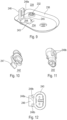
- the hose connector 104 is shown on its own in Figs. 3 and 4 . It may be made of a rigid material, such as rigid plastic.
- the front face 116 of the hose connector 104 is visible in Fig. 3
- a back face 118 of the hose connector 104 is visible in Fig. 4 .
- the hose connector 104 has a through-hole 120 for receiving the pivot shaft 2.
- the outer circumference 122 of the hose connector 104 may be fitted with a watertight seal. This seal may be made of rubber.
- the hose connector 104 has a fluid inlet port 124 on its back face 118 and a fluid outlet port 126 on its front face 116.
- the washer fluid hose 6 is connected to the fluid inlet port 124.
- another washer fluid hose which is secured to a windshield wiper to be attached to the pivot shaft 2, may be connected to the fluid outlet port 126.
- a check-valve may be arranged in the fluid inlet port 124. The purpose of such a check-valve is to prevent a backward flow of washer fluid from the fluid outlet port 126 to the fluid inlet port 124.
- the hose connector 104 consists of a plate-shaped main body 128 and an integral fluid tube 130 fastened to the main body 128.
- the fluid inlet port 124 and the fluid outlet port 126 are both part of the fluid tube 130.
- the fluid tube 130 traverses the front face 116 and the back face 118 of the hose connector 104.
- the fluid tube 130 is removably fastened in a fastening hole 132, which is formed in the main body 128.
- the main body 128 has a base plate 134 and an outer circumferential skirt 136 surrounding the base plate 134.
- the base plate 134 has a front surface 134a and a back surface 134b.
- the front surface 134a of the base plate 134 delimits the extent of the front face 116 of the hose connector 104.
- the base plate 134 is drop-shaped.
- the circumferential collar 115 of the cowl panel's opening 106 surrounds the outer circumferential skirt 136 of the hose connector 104.
- the hose connector 204 doubles as an electrical connector.
- This embodiment is dedicated to heated nozzle windshield wipers, i.e. nozzle windshield wipers, which have an integrated electrical heating device.
- the heating device improves the cleaning action of the nozzle windshield wiper during winter times.
- the hose connector 204 has an electrical interface 238.
- the electrical interface 238 allows to connect the electrical wiring of the heating device of a heated windshield wiper to an electrical power source behind the cowl panel 202.
- the electrical interface is a plug-and-socket assembly 238 with an electrical socket 240 and an electrical plug 242 received in the electrical socket 240.
- an aperture 244 having an edge 243 is formed in the main body 228 of the hose connector 204.
- the plug-and-socket assembly 238 is mounted in this aperture 244.
- the aperture 244 and the fastening hole 232 are preferably arranged side by side.
- the plug-and-socket assembly 238 does not take up the whole space defined by the aperture 244. Rather, there is a residual clearance 245 between the electrical plug 242 and the edge 243 of the aperture 244. This clearance 245 gives access to a latching clip 247 of the electrical plug 242 (cf. Fig. 10 ). Thanks to the clearance 245, the clip 247 can be unlatched from the electrical socket 240 and the plug 242 unplugged.
- the main body 228 also has a mounting lug 246, which is located next to the aperture 244, and which protrudes from the base plate 234.
- the electrical socket 240 is mounted on the mounting lug 246.
- the corresponding mounting joint may consist of a mounting rail 248a and a pair of mounting brackets 248b clasping the mounting rail 248a, cf. Fig. 12 .
- the mounting brackets 248b are part of the electrical socket 240, and the mounting rail 248a is arranged on the mounting lug 246. This could of course be interchanged.
- Cowl assembly with washer fluid transit - illustrative example
- Figs. 13 and 14 show a cowl assembly 300 with a cowl panel 302 and a hose connector 304.
- the hose connector 304 is surrounded by a circumferential ridge 350 formed in the cowl panel 302. This creates a depression 352, the bottom of which is taken up by the hose connector 304.
- a scupper 354 in the hose connector 304 ensures that rainwater is evacuated from the depression 352 so that it cannot accumulate therein.
- the hose connector 304 also has a mounting stud 356, which is inserted in a corresponding holding fixture 358 formed in the shaft supporting member 4.
- the cowl assemblies of the present disclosure simplify the assembly of the windshield wiper system.
- washer fluid hoses, and, if applicable, electrical wires can be connected with ease.
- the cowl assemblies also have a slim design, which is particularly suited for passenger cars.
- cowl assemblies also have good rainwater deflection properties.
Landscapes
- Engineering & Computer Science (AREA)
- Mechanical Engineering (AREA)
- Water Supply & Treatment (AREA)
- Chemical & Material Sciences (AREA)
- Combustion & Propulsion (AREA)
- Transportation (AREA)
- Body Structure For Vehicles (AREA)
Description
- This disclosure pertains to a vehicle windshield wiper cowl assembly comprising a protective cowl panel adapted to be mounted on the bodywork of a vehicle at the lower end of the vehicle's windshield, the cowl panel having a shaft opening for the pivot shaft of a windshield wiper, the shaft opening having a circumferential border area with a front side and a back side, wherein the border area front side defines a circumferential bordering surface, and a hose connector having a back face and a front face, wherein the hose connector is set into the cowl panel's shaft opening so that the hose connector is bordered by the shaft opening's circumferential border area.
- Such a vehicle windshield wiper cowl assembly is known from document
JP2010-012815A Figs. 1 and2 . This known cowl assembly comprises an outer cowl panel 17, an inner cowl panel 16 and an oval rubber grommet 40, which acts as a hose connector for two washer fluid hoses 35 and 38. The grommet 40 is set into a through-hole 16a of the inner cowl panel 16 and provides a watertight seal, which prevents water from entering the car body. As best seen inFig. 3 , the front face 41 b of the grommet 40 has a cup shape with a protruding circumferential sealing lip 47. The sealing lip 47 is in pressure contact with an inner surface 17b of the outer cowl panel 17, cf.Fig. 2 . - In this known configuration, rainwater may collect in the recess defined by the grommet's front face 41b. This is undesirable since the rainwater pool in the recess may degrade the outer cowl panel 17.
- The document
EP 3 381 754 A1 discloses a further configuration for a vehicle windshield wiper cowl assembly as known in the art. - In view of the above, it is an object of the present disclosure to provide a windshield wiper cowl assembly, which allows for the connection of washer fluid hoses therethrough, and which deflects rainwater effectively.
- According to the present disclosure, this object is achieved with a vehicle windshield wiper cowl assembly according to claim 1.
- Thanks to the inset hose connector, an assembly-line worker can easily and quickly connect a first washer fluid hose from below the cowl assembly, and a second washer fluid hose from above the cowl assembly.
- Furthermore, since the front face of the hose connector is on the same level as the surrounding cowl panel surface, rainwater hitting the cowl assembly on or close to the hose connector quickly drains off. Accordingly, there is very little accumulation of rainwater on the cowl assembly.
- The following features can be optionally implemented, separately or in combination:
- the hose connector has a through-hole for receiving the pivot shaft of a windshield wiper;
- the outer circumference of the hose connector is fitted with a watertight seal, which, preferably, is made of rubber;
- the hose connector is made of a rigid material, such as rigid plastic;
- the hose connector has a fluid inlet port on its back face and a fluid outlet port on its front face, both ports being adapted for connecting a washer fluid hose thereto;
- a check-valve is arranged in the fluid inlet port, the check-valve preventing a backward flow of washer fluid from the fluid outlet port to the fluid inlet port;
- the fluid inlet port and the fluid outlet port are both part of an integral fluid tube, which traverses the front and back face of the hose connector, wherein, preferably, the hose connector comprises a fastening hole and the fluid tube is removably fastened in the fastening hole;
- the hose connector has a base plate whose front surface is flush with the circumferential bordering surface defined by the border area front side and delimits the extent of the hose connector's front face;
- the hose connector's back face has an outer circumferential skirt surrounding the base plate;
- the border area back side of the cowl panel's shaft opening comprises a circumferential collar, which surrounds the outer circumferential skirt of the hose connector;
- the hose connector is also an electrical connector, which has an electrical interface allowing to connect the electrical wiring of an electrical heating device of a heated windshield wiper to an electrical power source behind the cowl panel;
- the electrical interface is a plug-and-socket assembly with an electrical socket and an electrical plug received in the electrical socket
- the plug-and-socket assembly is mounted in an aperture formed in the hose connector;
- the hose connector has a mounting lug, and the electrical socket is mounted on the mounting lug, preferably via a joint made of a mounting rail and a pair of mounting brackets clasping the mounting rail.
- The present disclosure also relates to a motor vehicle comprising a cowl assembly as defined above.
- Preferred embodiments of the present disclosure will now be described in detail with reference to the appended drawings, in which:
-
Fig. 1
[Fig. 1 ] is a front perspective view of a cowl assembly according to a first embodiment of the present disclosure. -
Fig. 2
[Fig. 2 ] is a back perspective view of the cowl assembly ofFig. 1 . -
Fig. 3
[Fig. 3 ] is a front perspective view of the hose connector of the cowl assembly ofFigs. 1 and2 . -
Fig. 4
[Fig. 4 ] is a back perspective view of the hose connector ofFig. 3 . -
Fig. 5
[Fig. 5 ] is a front perspective view of a cowl assembly according to a second embodiment of the present disclosure. -
Fig. 6
[Fig. 6 ] is a back perspective view of the cowl assembly ofFig. 5 . -
Fig. 7
[Fig. 7 ] is a front perspective view of the hose connector of the cowl assembly ofFigs. 5 and6 . -
Fig. 8
[Fig. 8 ] is a back perspective view of the hose connector ofFig. 7 . -
Fig. 9
[Fig. 9 ] is a back perspective view of the main body of the hose connector ofFigs. 7 and 8 . -
Fig. 10
[Fig. 10 ] is a perspective view of the electrical plug of the hose connector ofFigs. 7 and 8 . -
Fig. 11
[Fig. 11 ] is a perspective view of the electrical socket of the hose connector ofFigs. 7 and 8 . -
Fig. 12
[Fig. 12 ] is a cross-sectional view taken along line XII-XII inFig. 8 . -
Fig. 13
[Fig. 13 ] is a front perspective view of an exemplary cowl assembly with a different configuration than the embodiments of the present disclosure and not fallling under claim 1. -
Fig. 14
[Fig. 14 ] is a back perspective view of the cowl assembly ofFig. 13 . - The present disclosure is concerned with improvements to windshield wiper cowl assemblies, which are used as parts of vehicles, such as motor vehicles. The main component of such cowl assemblies is a cowl panel. Such a cowl panel is mounted on the bodywork of a vehicle at the lower end of the vehicle's windshield. Its main purpose is to cover and protect the driving linkage of the one or more windshield wipers from dirt, rainwater, debris or the like. Typically, such cowl panels have at least one shaft opening for the pivot shaft of a windshield wiper.
- In the present disclosure, the focus is on cowl assemblies that are especially suited for use with nozzle windshield wipers, i.e. windshield wipers having integrated nozzles for the spraying of washer fluid. These particular cowl assemblies comprise means allowing the washer fluid, which is supplied from a reservoir in the vehicle's body, to cross the cowl panel to reach the nozzle windshield wiper. This type of cowl assembly may be referred to as a cowl assembly with washer fluid transit.
- The figures show three different variants of cowl assemblies with washer fluid transit, wherein the first two variants are embodiments of the present disclosure, and the third variant is for further illustration.
- In the present context, the terms "front" and "back" are understood to have the following meaning:
The term "front" indicates that the corresponding element faces towards the outside of the vehicle when it is in an operational state and part of the vehicle. - The term "back" indicates that the corresponding element faces towards the inside of the vehicle when it is in an operational state and part of the vehicle.
- Referring to
Figs. 1 to 4 , we will now describe afirst embodiment 100 of a cowl assembly according to the present disclosure. -
Figs. 1 and2 show thecowl assembly 100 together with apivot shaft 2, ashaft supporting member 4, awasher fluid hose 6 and ahose clip 8. - The
pivot shaft 2 is made for pivoting a windshield wiper in a reciprocating manner. To that end, the head of a windshield wiper arm may be attached to thetop end 10 of thepivot shaft 2. Thebase 12 of thepivot shaft 2 is received in theshaft supporting member 4. - The
washer fluid hose 6 is secured to theshaft supporting member 4 via thehose clip 8. - The
cowl assembly 100 comprises aprotective cowl panel 102 and ahose connector 104. - The
protective cowl panel 102 is adapted to be mounted on the bodywork of a vehicle at the lower end of the vehicle's windshield. Thecowl panel 102 has ashaft opening 106. Thepivot shaft 2 extends through theshaft opening 106. Theshaft opening 106 has acircumferential border area 108. Afront side 110 of theborder area 108 is visible inFig.1 , and aback side 112 of theborder area 108 is visible inFig. 2 . Thefront side 110 of the border are 108 defines acircumferential bordering surface 114. - Here, the
back side 112 of theborder area 108 comprises acircumferential collar 115. - The
hose connector 104 is set into theshaft opening 106 of thecowl panel 102. Accordingly, thehose connector 104 is bordered by thecircumferential border area 108 of theshaft opening 106. - According to the present disclosure, a
front face 116 of thehose connector 104 is flush with thecircumferential bordering surface 114 defined by thefront side 110 of theborder area 108. - The
hose connector 104 is shown on its own inFigs. 3 and 4 . It may be made of a rigid material, such as rigid plastic. - The
front face 116 of thehose connector 104 is visible inFig. 3 , and aback face 118 of thehose connector 104 is visible inFig. 4 . - The
hose connector 104 has a through-hole 120 for receiving thepivot shaft 2. - The
outer circumference 122 of thehose connector 104 may be fitted with a watertight seal. This seal may be made of rubber. - The
hose connector 104 has afluid inlet port 124 on itsback face 118 and afluid outlet port 126 on itsfront face 116. InFigs. 1 and2 , thewasher fluid hose 6 is connected to thefluid inlet port 124. Likewise, another washer fluid hose, which is secured to a windshield wiper to be attached to thepivot shaft 2, may be connected to thefluid outlet port 126. - A check-valve may be arranged in the
fluid inlet port 124. The purpose of such a check-valve is to prevent a backward flow of washer fluid from thefluid outlet port 126 to thefluid inlet port 124. - In the present embodiment, the
hose connector 104 consists of a plate-shapedmain body 128 and anintegral fluid tube 130 fastened to themain body 128. In this case, thefluid inlet port 124 and thefluid outlet port 126 are both part of thefluid tube 130. - The
fluid tube 130 traverses thefront face 116 and theback face 118 of thehose connector 104. Preferably, thefluid tube 130 is removably fastened in afastening hole 132, which is formed in themain body 128. - The
main body 128 has abase plate 134 and an outercircumferential skirt 136 surrounding thebase plate 134. Thebase plate 134 has afront surface 134a and aback surface 134b. Thefront surface 134a of thebase plate 134 delimits the extent of thefront face 116 of thehose connector 104. - In the present example, the
base plate 134 is drop-shaped. - Turning back to
Fig. 1 , one can see that thefront surface 134a of thebase plate 134 is flush with thecircumferential bordering surface 114. - With reference to
Fig. 2 , thecircumferential collar 115 of the cowl panel'sopening 106 surrounds the outercircumferential skirt 136 of thehose connector 104. - With reference to
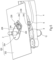
Figs. 5 to 12 , we will now describe asecond embodiment 200 of a cowl assembly according to the present disclosure. - In the following, only the differences with respect to the
first embodiment 100 will be detailed. For similar elements, reference is made to the description above. - In this second embodiment, the
hose connector 204 doubles as an electrical connector. This embodiment is dedicated to heated nozzle windshield wipers, i.e. nozzle windshield wipers, which have an integrated electrical heating device. The heating device improves the cleaning action of the nozzle windshield wiper during winter times. - To this end, the
hose connector 204 has anelectrical interface 238. Theelectrical interface 238 allows to connect the electrical wiring of the heating device of a heated windshield wiper to an electrical power source behind thecowl panel 202. - Here, the electrical interface is a plug-and-
socket assembly 238 with anelectrical socket 240 and anelectrical plug 242 received in theelectrical socket 240. - As can be seen in
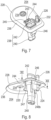
Fig. 9 , anaperture 244 having anedge 243 is formed in themain body 228 of thehose connector 204. The plug-and-socket assembly 238 is mounted in thisaperture 244. Theaperture 244 and thefastening hole 232 are preferably arranged side by side. - As best apparent from
Fig. 7 , the plug-and-socket assembly 238 does not take up the whole space defined by theaperture 244. Rather, there is aresidual clearance 245 between theelectrical plug 242 and theedge 243 of theaperture 244. Thisclearance 245 gives access to alatching clip 247 of the electrical plug 242 (cf.Fig. 10 ). Thanks to theclearance 245, theclip 247 can be unlatched from theelectrical socket 240 and theplug 242 unplugged. - The
main body 228 also has a mountinglug 246, which is located next to theaperture 244, and which protrudes from thebase plate 234. Theelectrical socket 240 is mounted on the mountinglug 246. The corresponding mounting joint may consist of a mountingrail 248a and a pair of mountingbrackets 248b clasping the mountingrail 248a, cf.Fig. 12 . - Here, the mounting
brackets 248b are part of theelectrical socket 240, and the mountingrail 248a is arranged on the mountinglug 246. This could of course be interchanged. -
Figs. 13 and14 show acowl assembly 300 with acowl panel 302 and ahose connector 304. In this unclaimed example, thehose connector 304 is surrounded by acircumferential ridge 350 formed in thecowl panel 302. This creates adepression 352, the bottom of which is taken up by thehose connector 304. - A
scupper 354 in thehose connector 304 ensures that rainwater is evacuated from thedepression 352 so that it cannot accumulate therein. - The
hose connector 304 also has a mountingstud 356, which is inserted in acorresponding holding fixture 358 formed in theshaft supporting member 4. - As part of a complete windshield wiper system, the cowl assemblies of the present disclosure simplify the assembly of the windshield wiper system. In particular, washer fluid hoses, and, if applicable, electrical wires, can be connected with ease.
- The cowl assemblies also have a slim design, which is particularly suited for passenger cars.
- Furthermore, the cowl assemblies also have good rainwater deflection properties.
Claims (12)
- A vehicle windshield wiper cowl assembly (100) comprising:a. a protective cowl panel (102) adapted to be mounted on the bodywork of a vehicle at the lower end of the vehicle's windshield, the cowl panel (102) having a shaft opening (106) for the pivot shaft (2) of a windshield wiper, the shaft opening (106) having a circumferential border area (108) with a front side (110) and a back side (112), wherein the border area front side (110) defines a circumferential bordering surface (114); andb. a hose connector (104) having a front face (116), and a base plate (134), a front surface (134a) of the base plate being flush with the circumferential bordering surface (114) defined by the border area front side (110) and delimiting the extent of the hose connector front face (116), and a back face (118) having an outer circumferential skirt (136) surrounding the base plate (134), wherein the hose connector is set into the cowl panel's shaft opening (106) so that the hose connector (104) is bordered by the shaft opening's circumferential border area (108);wherein the front face (116) of the hose connector (104) is flush with the circumferential bordering surface (114) defined by the border area front side (110), characterised in that the border area back side (112) of the cowl panel shaft opening (106) comprising a circumferential collar (115) surrounding the outer circumferential skirt (136) of the hose connector.
- The cowl assembly (100) of claim 1, wherein the hose connector (104) has a through-hole (120) for receiving the pivot shaft (2) of a windshield wiper.
- The cowl assembly (100) of any one of the previous claims, wherein the outer circumference (122) of the hose connector (104) is fitted with a watertight seal, which, preferably, is made of rubber.
- The cowl assembly (100) of any one of the previous claims, wherein the hose connector (104) is made of a rigid material, such as rigid plastic.
- The cowl assembly (100) of any one of the previous claims, wherein the hose connector (104) has a fluid inlet port (124) on its back face (118) and a fluid outlet port (126) on its front face (116), both ports being adapted for connecting a washer fluid hose (6) thereto.
- The cowl assembly (100) of claim 5, wherein a check-valve is arranged in the fluid inlet port (124), the check-valve preventing a backward flow of washer fluid from the fluid outlet port to the fluid inlet port.
- The cowl assembly (100) of claim 5 or 6, wherein the fluid inlet port (124) and the fluid outlet port (126) are both part of an integral fluid tube (130), which traverses the front and back face of the hose connector (104), wherein, preferably, the hose connector comprises a fastening hole (132) and the fluid tube (130) is removably fastened in the fastening hole.
- The cowl assembly (200) of any one of the previous claims, wherein the hose connector (204) is also an electrical connector, which has an electrical interface (238) allowing to connect the electrical wiring of an electrical heating device of a heated windshield wiper to an electrical power source behind the cowl panel (202).
- The cowl assembly (200) of claim 8, wherein the electrical interface is a plug-and-socket assembly (238) with an electrical socket (240) and an electrical plug (242) received in the electrical socket (240).
- The cowl assembly (200) of claim 9, wherein the plug-and-socket assembly is mounted in an aperture (244) formed in the hose connector.
- The cowl assembly (200) of claim 9 or 10, wherein the hose connector (204) has a mounting lug (246), and the electrical socket (240) is mounted on the mounting lug, preferably via a joint made of a mounting rail (248a) and a pair of mounting brackets (248b) clasping the mounting rail.
- A motor vehicle comprising the cowl assembly (100, 200) of any one of the previous claims.
Priority Applications (4)
| Application Number | Priority Date | Filing Date | Title |
|---|---|---|---|
| EP21188874.8A EP4124517B1 (en) | 2021-07-30 | 2021-07-30 | A windshield wiper cowl assembly with a flush-mounted inset hose connector |
| US18/291,322 US20250115303A1 (en) | 2021-07-30 | 2022-07-26 | Windshield wiper cowl assembly with a flush-mounted inset hose connector |
| CN202280053320.6A CN117769508A (en) | 2021-07-30 | 2022-07-26 | Windshield wiper shroud assembly with flush-mounted recessed hose connections |
| PCT/EP2022/070933 WO2023006740A1 (en) | 2021-07-30 | 2022-07-26 | A windshield wiper cowl assembly with a flush-mounted inset hose connector |
Applications Claiming Priority (1)
| Application Number | Priority Date | Filing Date | Title |
|---|---|---|---|
| EP21188874.8A EP4124517B1 (en) | 2021-07-30 | 2021-07-30 | A windshield wiper cowl assembly with a flush-mounted inset hose connector |
Publications (2)
| Publication Number | Publication Date |
|---|---|
| EP4124517A1 EP4124517A1 (en) | 2023-02-01 |
| EP4124517B1 true EP4124517B1 (en) | 2024-11-20 |
Family
ID=77167988
Family Applications (1)
| Application Number | Title | Priority Date | Filing Date |
|---|---|---|---|
| EP21188874.8A Active EP4124517B1 (en) | 2021-07-30 | 2021-07-30 | A windshield wiper cowl assembly with a flush-mounted inset hose connector |
Country Status (4)
| Country | Link |
|---|---|
| US (1) | US20250115303A1 (en) |
| EP (1) | EP4124517B1 (en) |
| CN (1) | CN117769508A (en) |
| WO (1) | WO2023006740A1 (en) |
Family Cites Families (21)
| Publication number | Priority date | Publication date | Assignee | Title |
|---|---|---|---|---|
| US2627011A (en) * | 1949-04-05 | 1953-01-27 | William C Eaves | Heating device for window cleaners |
| US2869166A (en) * | 1956-04-12 | 1959-01-20 | William C Eaves | Heating or deicing unit for glazed windows |
| US3910652A (en) * | 1974-03-29 | 1975-10-07 | Trico Products Corp | Self-dimensioning bearing assembly |
| JPH0544217Y2 (en) * | 1987-07-08 | 1993-11-09 | ||
| FI85356C (en) * | 1989-12-13 | 1992-04-10 | Keijo Vornanen | TORK- OCH TVAETTANORDNING FOER VINDRUTAN I ETT FORDON. |
| US5203049A (en) * | 1991-05-20 | 1993-04-20 | Jidosha Denki Kogyo Kabushiki Kaisha | Wiper apparatus with mechanism for switching spraying direction of washing fluid |
| DE19501210A1 (en) * | 1995-01-17 | 1996-07-18 | Teves Gmbh Alfred | Module for a motor vehicle |
| FR2733473B1 (en) * | 1995-04-28 | 1997-06-06 | Valeo Systemes Dessuyage | WINDSCREEN WIPER MECHANISM COMPRISING IMPROVED SEALING MEANS |
| JP3634303B2 (en) * | 2001-12-12 | 2005-03-30 | 本田技研工業株式会社 | Energy absorption wiper structure for vehicles |
| US6742827B1 (en) * | 2002-11-27 | 2004-06-01 | Valeo Electrical Systems, Inc. | Plug-n-play module with integral motor connector |
| US6981737B2 (en) * | 2003-11-26 | 2006-01-03 | Denso International America, Inc. | Double plate heater pipe seal to dash |
| JP5347313B2 (en) * | 2008-04-18 | 2013-11-20 | スズキ株式会社 | Vehicle cowl structure |
| JP2010012815A (en) | 2008-07-01 | 2010-01-21 | Mitsuba Corp | Wiper device |
| DE102008063112A1 (en) * | 2008-12-24 | 2009-09-03 | Daimler Ag | Wiper arrangement for panel, particularly wind protection panel of vehicle, has wiper shaft that penetrates through covering in area of nozzle, and wiper shaft actuates disk wiper |
| US8840173B2 (en) * | 2011-07-11 | 2014-09-23 | Nissan North America, Inc. | Water shield for a wiper drive assembly |
| US8641130B2 (en) * | 2011-09-23 | 2014-02-04 | Nissan North America, Inc. | Vehicle cowl cover |
| CN102935836B (en) * | 2012-11-20 | 2015-06-10 | 奇瑞汽车股份有限公司 | Device for cleaning rear windshield of car and the car |
| DE102012222044B4 (en) * | 2012-12-03 | 2025-02-13 | Continental Automotive Technologies GmbH | Hydraulic cleaning system |
| CN103600725B (en) * | 2013-11-14 | 2016-03-16 | 奇瑞汽车股份有限公司 | A kind of back vehicle windshield glass washing device and vehicle |
| FR3064232B1 (en) * | 2017-03-27 | 2021-06-04 | Valeo Systemes Dessuyage | WIPER BLADE CAP AND ARM FOR MOTOR VEHICLES |
| CN209667032U (en) * | 2019-04-03 | 2019-11-22 | 周凡石 | A kind of windshield wiper for preventing windshield from scratching |
-
2021
- 2021-07-30 EP EP21188874.8A patent/EP4124517B1/en active Active
-
2022
- 2022-07-26 US US18/291,322 patent/US20250115303A1/en active Pending
- 2022-07-26 WO PCT/EP2022/070933 patent/WO2023006740A1/en not_active Ceased
- 2022-07-26 CN CN202280053320.6A patent/CN117769508A/en active Pending
Also Published As
| Publication number | Publication date |
|---|---|
| WO2023006740A1 (en) | 2023-02-02 |
| US20250115303A1 (en) | 2025-04-10 |
| CN117769508A (en) | 2024-03-26 |
| EP4124517A1 (en) | 2023-02-01 |
Similar Documents
| Publication | Publication Date | Title |
|---|---|---|
| US7895703B2 (en) | Backdoor apparatus | |
| US6113006A (en) | Snap together window washer nozzle | |
| US7988224B2 (en) | Cowl cover assembly for a motor vehicle | |
| CN104428178B (en) | Wiper blades with hydraulic connectors | |
| US20220212632A1 (en) | Wind deflector for a windscreen wiper system of a motor vehicle | |
| US7316447B2 (en) | Integrated motor vehicle cowl vent and seal | |
| EP4124517B1 (en) | A windshield wiper cowl assembly with a flush-mounted inset hose connector | |
| US8840173B2 (en) | Water shield for a wiper drive assembly | |
| CN101362457B (en) | Washer nozzle | |
| JP2004501826A (en) | Link for windshield wiper | |
| CN201321019Y (en) | Nozzle and scrubber with said nozzle | |
| US11858474B2 (en) | Wind deflector for a window wiper system of a motor vehicle | |
| JP3866351B2 (en) | Automobile hood seal mounting structure | |
| US20230356695A1 (en) | Wind deflector for a windscreen wiper system of a motor vehicle | |
| JPS5942293Y2 (en) | Cleaning liquid injection device for rear window glass | |
| JP7649473B2 (en) | Vehicle front structure | |
| JPH0531000Y2 (en) | ||
| JP3678055B2 (en) | Front body structure of the vehicle | |
| KR0126085B1 (en) | Mounting structure of vehicle cowl | |
| JP7688133B2 (en) | Wiper arm, wiper and vehicle | |
| US20250360968A1 (en) | Vehicle fluid management assembly | |
| JPS5943340B2 (en) | Mounting structure of vehicle wash nozzle | |
| CN210139853U (en) | Cleaning device and automobile | |
| KR100297409B1 (en) | Structure for installing cowl grille with washing nozzle | |
| KR19980023084A (en) | Washer Integral Car Wiper Assembly Structure |
Legal Events
| Date | Code | Title | Description |
|---|---|---|---|
| PUAI | Public reference made under article 153(3) epc to a published international application that has entered the european phase |
Free format text: ORIGINAL CODE: 0009012 |
|
| STAA | Information on the status of an ep patent application or granted ep patent |
Free format text: STATUS: THE APPLICATION HAS BEEN PUBLISHED |
|
| AK | Designated contracting states |
Kind code of ref document: A1 Designated state(s): AL AT BE BG CH CY CZ DE DK EE ES FI FR GB GR HR HU IE IS IT LI LT LU LV MC MK MT NL NO PL PT RO RS SE SI SK SM TR |
|
| STAA | Information on the status of an ep patent application or granted ep patent |
Free format text: STATUS: REQUEST FOR EXAMINATION WAS MADE |
|
| 17P | Request for examination filed |
Effective date: 20230731 |
|
| RBV | Designated contracting states (corrected) |
Designated state(s): AL AT BE BG CH CY CZ DE DK EE ES FI FR GB GR HR HU IE IS IT LI LT LU LV MC MK MT NL NO PL PT RO RS SE SI SK SM TR |
|
| GRAP | Despatch of communication of intention to grant a patent |
Free format text: ORIGINAL CODE: EPIDOSNIGR1 |
|
| STAA | Information on the status of an ep patent application or granted ep patent |
Free format text: STATUS: GRANT OF PATENT IS INTENDED |
|
| RIC1 | Information provided on ipc code assigned before grant |
Ipc: B62D 25/08 20060101ALI20240507BHEP Ipc: B60S 1/48 20060101ALI20240507BHEP Ipc: B60S 1/34 20060101AFI20240507BHEP |
|
| INTG | Intention to grant announced |
Effective date: 20240610 |
|
| GRAS | Grant fee paid |
Free format text: ORIGINAL CODE: EPIDOSNIGR3 |
|
| GRAA | (expected) grant |
Free format text: ORIGINAL CODE: 0009210 |
|
| STAA | Information on the status of an ep patent application or granted ep patent |
Free format text: STATUS: THE PATENT HAS BEEN GRANTED |
|
| AK | Designated contracting states |
Kind code of ref document: B1 Designated state(s): AL AT BE BG CH CY CZ DE DK EE ES FI FR GB GR HR HU IE IS IT LI LT LU LV MC MK MT NL NO PL PT RO RS SE SI SK SM TR |
|
| REG | Reference to a national code |
Ref country code: GB Ref legal event code: FG4D |
|
| REG | Reference to a national code |
Ref country code: CH Ref legal event code: EP |
|
| REG | Reference to a national code |
Ref country code: DE Ref legal event code: R096 Ref document number: 602021021997 Country of ref document: DE |
|
| REG | Reference to a national code |
Ref country code: IE Ref legal event code: FG4D |
|
| REG | Reference to a national code |
Ref country code: LT Ref legal event code: MG9D |
|
| REG | Reference to a national code |
Ref country code: NL Ref legal event code: MP Effective date: 20241120 |
|
| PG25 | Lapsed in a contracting state [announced via postgrant information from national office to epo] |
Ref country code: HR Free format text: LAPSE BECAUSE OF FAILURE TO SUBMIT A TRANSLATION OF THE DESCRIPTION OR TO PAY THE FEE WITHIN THE PRESCRIBED TIME-LIMIT Effective date: 20241120 Ref country code: IS Free format text: LAPSE BECAUSE OF FAILURE TO SUBMIT A TRANSLATION OF THE DESCRIPTION OR TO PAY THE FEE WITHIN THE PRESCRIBED TIME-LIMIT Effective date: 20250320 Ref country code: PT Free format text: LAPSE BECAUSE OF FAILURE TO SUBMIT A TRANSLATION OF THE DESCRIPTION OR TO PAY THE FEE WITHIN THE PRESCRIBED TIME-LIMIT Effective date: 20250320 |
|
| PG25 | Lapsed in a contracting state [announced via postgrant information from national office to epo] |
Ref country code: FI Free format text: LAPSE BECAUSE OF FAILURE TO SUBMIT A TRANSLATION OF THE DESCRIPTION OR TO PAY THE FEE WITHIN THE PRESCRIBED TIME-LIMIT Effective date: 20241120 Ref country code: NL Free format text: LAPSE BECAUSE OF FAILURE TO SUBMIT A TRANSLATION OF THE DESCRIPTION OR TO PAY THE FEE WITHIN THE PRESCRIBED TIME-LIMIT Effective date: 20241120 |
|
| REG | Reference to a national code |
Ref country code: AT Ref legal event code: MK05 Ref document number: 1743317 Country of ref document: AT Kind code of ref document: T Effective date: 20241120 |
|
| PG25 | Lapsed in a contracting state [announced via postgrant information from national office to epo] |
Ref country code: BG Free format text: LAPSE BECAUSE OF FAILURE TO SUBMIT A TRANSLATION OF THE DESCRIPTION OR TO PAY THE FEE WITHIN THE PRESCRIBED TIME-LIMIT Effective date: 20241120 |
|
| PG25 | Lapsed in a contracting state [announced via postgrant information from national office to epo] |
Ref country code: ES Free format text: LAPSE BECAUSE OF FAILURE TO SUBMIT A TRANSLATION OF THE DESCRIPTION OR TO PAY THE FEE WITHIN THE PRESCRIBED TIME-LIMIT Effective date: 20241120 |
|
| PG25 | Lapsed in a contracting state [announced via postgrant information from national office to epo] |
Ref country code: NO Free format text: LAPSE BECAUSE OF FAILURE TO SUBMIT A TRANSLATION OF THE DESCRIPTION OR TO PAY THE FEE WITHIN THE PRESCRIBED TIME-LIMIT Effective date: 20250220 |
|
| PG25 | Lapsed in a contracting state [announced via postgrant information from national office to epo] |
Ref country code: LV Free format text: LAPSE BECAUSE OF FAILURE TO SUBMIT A TRANSLATION OF THE DESCRIPTION OR TO PAY THE FEE WITHIN THE PRESCRIBED TIME-LIMIT Effective date: 20241120 Ref country code: AT Free format text: LAPSE BECAUSE OF FAILURE TO SUBMIT A TRANSLATION OF THE DESCRIPTION OR TO PAY THE FEE WITHIN THE PRESCRIBED TIME-LIMIT Effective date: 20241120 Ref country code: GR Free format text: LAPSE BECAUSE OF FAILURE TO SUBMIT A TRANSLATION OF THE DESCRIPTION OR TO PAY THE FEE WITHIN THE PRESCRIBED TIME-LIMIT Effective date: 20250221 |
|
| PG25 | Lapsed in a contracting state [announced via postgrant information from national office to epo] |
Ref country code: PL Free format text: LAPSE BECAUSE OF FAILURE TO SUBMIT A TRANSLATION OF THE DESCRIPTION OR TO PAY THE FEE WITHIN THE PRESCRIBED TIME-LIMIT Effective date: 20241120 |
|
| PG25 | Lapsed in a contracting state [announced via postgrant information from national office to epo] |
Ref country code: RS Free format text: LAPSE BECAUSE OF FAILURE TO SUBMIT A TRANSLATION OF THE DESCRIPTION OR TO PAY THE FEE WITHIN THE PRESCRIBED TIME-LIMIT Effective date: 20250220 |
|
| PG25 | Lapsed in a contracting state [announced via postgrant information from national office to epo] |
Ref country code: SM Free format text: LAPSE BECAUSE OF FAILURE TO SUBMIT A TRANSLATION OF THE DESCRIPTION OR TO PAY THE FEE WITHIN THE PRESCRIBED TIME-LIMIT Effective date: 20241120 |
|
| PG25 | Lapsed in a contracting state [announced via postgrant information from national office to epo] |
Ref country code: DK Free format text: LAPSE BECAUSE OF FAILURE TO SUBMIT A TRANSLATION OF THE DESCRIPTION OR TO PAY THE FEE WITHIN THE PRESCRIBED TIME-LIMIT Effective date: 20241120 |
|
| PG25 | Lapsed in a contracting state [announced via postgrant information from national office to epo] |
Ref country code: EE Free format text: LAPSE BECAUSE OF FAILURE TO SUBMIT A TRANSLATION OF THE DESCRIPTION OR TO PAY THE FEE WITHIN THE PRESCRIBED TIME-LIMIT Effective date: 20241120 |
|
| PG25 | Lapsed in a contracting state [announced via postgrant information from national office to epo] |
Ref country code: RO Free format text: LAPSE BECAUSE OF FAILURE TO SUBMIT A TRANSLATION OF THE DESCRIPTION OR TO PAY THE FEE WITHIN THE PRESCRIBED TIME-LIMIT Effective date: 20241120 |
|
| PG25 | Lapsed in a contracting state [announced via postgrant information from national office to epo] |
Ref country code: SK Free format text: LAPSE BECAUSE OF FAILURE TO SUBMIT A TRANSLATION OF THE DESCRIPTION OR TO PAY THE FEE WITHIN THE PRESCRIBED TIME-LIMIT Effective date: 20241120 |
|
| PG25 | Lapsed in a contracting state [announced via postgrant information from national office to epo] |
Ref country code: CZ Free format text: LAPSE BECAUSE OF FAILURE TO SUBMIT A TRANSLATION OF THE DESCRIPTION OR TO PAY THE FEE WITHIN THE PRESCRIBED TIME-LIMIT Effective date: 20241120 |
|
| PG25 | Lapsed in a contracting state [announced via postgrant information from national office to epo] |
Ref country code: IT Free format text: LAPSE BECAUSE OF FAILURE TO SUBMIT A TRANSLATION OF THE DESCRIPTION OR TO PAY THE FEE WITHIN THE PRESCRIBED TIME-LIMIT Effective date: 20241120 |
|
| REG | Reference to a national code |
Ref country code: DE Ref legal event code: R097 Ref document number: 602021021997 Country of ref document: DE |
|
| PG25 | Lapsed in a contracting state [announced via postgrant information from national office to epo] |
Ref country code: SE Free format text: LAPSE BECAUSE OF FAILURE TO SUBMIT A TRANSLATION OF THE DESCRIPTION OR TO PAY THE FEE WITHIN THE PRESCRIBED TIME-LIMIT Effective date: 20241120 |
|
| PLBE | No opposition filed within time limit |
Free format text: ORIGINAL CODE: 0009261 |
|
| STAA | Information on the status of an ep patent application or granted ep patent |
Free format text: STATUS: NO OPPOSITION FILED WITHIN TIME LIMIT |
|
| PGFP | Annual fee paid to national office [announced via postgrant information from national office to epo] |
Ref country code: DE Payment date: 20250711 Year of fee payment: 5 |
|
| PGFP | Annual fee paid to national office [announced via postgrant information from national office to epo] |
Ref country code: FR Payment date: 20250730 Year of fee payment: 5 |
|
| 26N | No opposition filed |
Effective date: 20250821 |
|
| REG | Reference to a national code |
Ref country code: CH Ref legal event code: H13 Free format text: ST27 STATUS EVENT CODE: U-0-0-H10-H13 (AS PROVIDED BY THE NATIONAL OFFICE) Effective date: 20260224 |
|
| PG25 | Lapsed in a contracting state [announced via postgrant information from national office to epo] |
Ref country code: LU Free format text: LAPSE BECAUSE OF NON-PAYMENT OF DUE FEES Effective date: 20250730 |
|
| GBPC | Gb: european patent ceased through non-payment of renewal fee |
Effective date: 20250730 |
|
| REG | Reference to a national code |
Ref country code: BE Ref legal event code: MM Effective date: 20250731 |
|
| PG25 | Lapsed in a contracting state [announced via postgrant information from national office to epo] |
Ref country code: GB Free format text: LAPSE BECAUSE OF NON-PAYMENT OF DUE FEES Effective date: 20250730 |
|
| PG25 | Lapsed in a contracting state [announced via postgrant information from national office to epo] |
Ref country code: BE Free format text: LAPSE BECAUSE OF NON-PAYMENT OF DUE FEES Effective date: 20250731 |
|
| PG25 | Lapsed in a contracting state [announced via postgrant information from national office to epo] |
Ref country code: CH Free format text: LAPSE BECAUSE OF NON-PAYMENT OF DUE FEES Effective date: 20250731 |