EP4124500B1 - Ladesteuerungsverfahren, ladesystem und entsprechende vorrichtung - Google Patents
Ladesteuerungsverfahren, ladesystem und entsprechende vorrichtung Download PDFInfo
- Publication number
- EP4124500B1 EP4124500B1 EP22187968.7A EP22187968A EP4124500B1 EP 4124500 B1 EP4124500 B1 EP 4124500B1 EP 22187968 A EP22187968 A EP 22187968A EP 4124500 B1 EP4124500 B1 EP 4124500B1
- Authority
- EP
- European Patent Office
- Prior art keywords
- charging
- load
- charger
- electricity consumption
- campus
- Prior art date
- Legal status (The legal status is an assumption and is not a legal conclusion. Google has not performed a legal analysis and makes no representation as to the accuracy of the status listed.)
- Active
Links
Images


Classifications
-
- B—PERFORMING OPERATIONS; TRANSPORTING
- B60—VEHICLES IN GENERAL
- B60L—PROPULSION OF ELECTRICALLY-PROPELLED VEHICLES; SUPPLYING ELECTRIC POWER FOR AUXILIARY EQUIPMENT OF ELECTRICALLY-PROPELLED VEHICLES; ELECTRODYNAMIC BRAKE SYSTEMS FOR VEHICLES IN GENERAL; MAGNETIC SUSPENSION OR LEVITATION FOR VEHICLES; MONITORING OPERATING VARIABLES OF ELECTRICALLY-PROPELLED VEHICLES; ELECTRIC SAFETY DEVICES FOR ELECTRICALLY-PROPELLED VEHICLES
- B60L53/00—Methods of charging batteries, specially adapted for electric vehicles; Charging stations or on-board charging equipment therefor; Exchange of energy storage elements in electric vehicles
- B60L53/60—Monitoring or controlling charging stations
- B60L53/62—Monitoring or controlling charging stations in response to charging parameters, e.g. current, voltage or electrical charge
-
- B—PERFORMING OPERATIONS; TRANSPORTING
- B60—VEHICLES IN GENERAL
- B60L—PROPULSION OF ELECTRICALLY-PROPELLED VEHICLES; SUPPLYING ELECTRIC POWER FOR AUXILIARY EQUIPMENT OF ELECTRICALLY-PROPELLED VEHICLES; ELECTRODYNAMIC BRAKE SYSTEMS FOR VEHICLES IN GENERAL; MAGNETIC SUSPENSION OR LEVITATION FOR VEHICLES; MONITORING OPERATING VARIABLES OF ELECTRICALLY-PROPELLED VEHICLES; ELECTRIC SAFETY DEVICES FOR ELECTRICALLY-PROPELLED VEHICLES
- B60L53/00—Methods of charging batteries, specially adapted for electric vehicles; Charging stations or on-board charging equipment therefor; Exchange of energy storage elements in electric vehicles
- B60L53/50—Charging stations characterised by energy-storage or power-generation means
- B60L53/53—Batteries
-
- B—PERFORMING OPERATIONS; TRANSPORTING
- B60—VEHICLES IN GENERAL
- B60L—PROPULSION OF ELECTRICALLY-PROPELLED VEHICLES; SUPPLYING ELECTRIC POWER FOR AUXILIARY EQUIPMENT OF ELECTRICALLY-PROPELLED VEHICLES; ELECTRODYNAMIC BRAKE SYSTEMS FOR VEHICLES IN GENERAL; MAGNETIC SUSPENSION OR LEVITATION FOR VEHICLES; MONITORING OPERATING VARIABLES OF ELECTRICALLY-PROPELLED VEHICLES; ELECTRIC SAFETY DEVICES FOR ELECTRICALLY-PROPELLED VEHICLES
- B60L53/00—Methods of charging batteries, specially adapted for electric vehicles; Charging stations or on-board charging equipment therefor; Exchange of energy storage elements in electric vehicles
- B60L53/60—Monitoring or controlling charging stations
- B60L53/63—Monitoring or controlling charging stations in response to network capacity
-
- B—PERFORMING OPERATIONS; TRANSPORTING
- B60—VEHICLES IN GENERAL
- B60L—PROPULSION OF ELECTRICALLY-PROPELLED VEHICLES; SUPPLYING ELECTRIC POWER FOR AUXILIARY EQUIPMENT OF ELECTRICALLY-PROPELLED VEHICLES; ELECTRODYNAMIC BRAKE SYSTEMS FOR VEHICLES IN GENERAL; MAGNETIC SUSPENSION OR LEVITATION FOR VEHICLES; MONITORING OPERATING VARIABLES OF ELECTRICALLY-PROPELLED VEHICLES; ELECTRIC SAFETY DEVICES FOR ELECTRICALLY-PROPELLED VEHICLES
- B60L53/00—Methods of charging batteries, specially adapted for electric vehicles; Charging stations or on-board charging equipment therefor; Exchange of energy storage elements in electric vehicles
- B60L53/60—Monitoring or controlling charging stations
- B60L53/65—Monitoring or controlling charging stations involving identification of vehicles or their battery types
-
- B—PERFORMING OPERATIONS; TRANSPORTING
- B60—VEHICLES IN GENERAL
- B60L—PROPULSION OF ELECTRICALLY-PROPELLED VEHICLES; SUPPLYING ELECTRIC POWER FOR AUXILIARY EQUIPMENT OF ELECTRICALLY-PROPELLED VEHICLES; ELECTRODYNAMIC BRAKE SYSTEMS FOR VEHICLES IN GENERAL; MAGNETIC SUSPENSION OR LEVITATION FOR VEHICLES; MONITORING OPERATING VARIABLES OF ELECTRICALLY-PROPELLED VEHICLES; ELECTRIC SAFETY DEVICES FOR ELECTRICALLY-PROPELLED VEHICLES
- B60L53/00—Methods of charging batteries, specially adapted for electric vehicles; Charging stations or on-board charging equipment therefor; Exchange of energy storage elements in electric vehicles
- B60L53/60—Monitoring or controlling charging stations
- B60L53/66—Data transfer between charging stations and vehicles
- B60L53/665—Methods related to measuring, billing or payment
-
- B—PERFORMING OPERATIONS; TRANSPORTING
- B60—VEHICLES IN GENERAL
- B60L—PROPULSION OF ELECTRICALLY-PROPELLED VEHICLES; SUPPLYING ELECTRIC POWER FOR AUXILIARY EQUIPMENT OF ELECTRICALLY-PROPELLED VEHICLES; ELECTRODYNAMIC BRAKE SYSTEMS FOR VEHICLES IN GENERAL; MAGNETIC SUSPENSION OR LEVITATION FOR VEHICLES; MONITORING OPERATING VARIABLES OF ELECTRICALLY-PROPELLED VEHICLES; ELECTRIC SAFETY DEVICES FOR ELECTRICALLY-PROPELLED VEHICLES
- B60L53/00—Methods of charging batteries, specially adapted for electric vehicles; Charging stations or on-board charging equipment therefor; Exchange of energy storage elements in electric vehicles
- B60L53/60—Monitoring or controlling charging stations
- B60L53/67—Controlling two or more charging stations
-
- B—PERFORMING OPERATIONS; TRANSPORTING
- B60—VEHICLES IN GENERAL
- B60L—PROPULSION OF ELECTRICALLY-PROPELLED VEHICLES; SUPPLYING ELECTRIC POWER FOR AUXILIARY EQUIPMENT OF ELECTRICALLY-PROPELLED VEHICLES; ELECTRODYNAMIC BRAKE SYSTEMS FOR VEHICLES IN GENERAL; MAGNETIC SUSPENSION OR LEVITATION FOR VEHICLES; MONITORING OPERATING VARIABLES OF ELECTRICALLY-PROPELLED VEHICLES; ELECTRIC SAFETY DEVICES FOR ELECTRICALLY-PROPELLED VEHICLES
- B60L53/00—Methods of charging batteries, specially adapted for electric vehicles; Charging stations or on-board charging equipment therefor; Exchange of energy storage elements in electric vehicles
- B60L53/60—Monitoring or controlling charging stations
- B60L53/68—Off-site monitoring or control, e.g. remote control
-
- H—ELECTRICITY
- H02—GENERATION; CONVERSION OR DISTRIBUTION OF ELECTRIC POWER
- H02J—ELECTRIC POWER NETWORKS; CIRCUIT ARRANGEMENTS OR SYSTEMS FOR SUPPLYING OR DISTRIBUTING ELECTRIC POWER; SYSTEMS FOR STORING ELECTRIC ENERGY
- H02J1/00—Circuit arrangements for DC mains or DC distribution networks
- H02J1/10—Parallel operation of DC sources
- H02J1/106—Parallel operation of DC sources for load balancing, symmetrisation, or sharing
-
- H—ELECTRICITY
- H02—GENERATION; CONVERSION OR DISTRIBUTION OF ELECTRIC POWER
- H02J—ELECTRIC POWER NETWORKS; CIRCUIT ARRANGEMENTS OR SYSTEMS FOR SUPPLYING OR DISTRIBUTING ELECTRIC POWER; SYSTEMS FOR STORING ELECTRIC ENERGY
- H02J7/00—Circuit arrangements for charging or discharging batteries or for supplying loads from batteries
- H02J7/02—Circuit arrangements for charging or discharging batteries or for supplying loads from batteries for charging batteries from AC mains by converters
-
- H—ELECTRICITY
- H02—GENERATION; CONVERSION OR DISTRIBUTION OF ELECTRIC POWER
- H02J—ELECTRIC POWER NETWORKS; CIRCUIT ARRANGEMENTS OR SYSTEMS FOR SUPPLYING OR DISTRIBUTING ELECTRIC POWER; SYSTEMS FOR STORING ELECTRIC ENERGY
- H02J7/00—Circuit arrangements for charging or discharging batteries or for supplying loads from batteries
- H02J7/50—Circuit arrangements for charging or discharging batteries or for supplying loads from batteries acting upon multiple batteries simultaneously or sequentially
-
- H—ELECTRICITY
- H02—GENERATION; CONVERSION OR DISTRIBUTION OF ELECTRIC POWER
- H02J—ELECTRIC POWER NETWORKS; CIRCUIT ARRANGEMENTS OR SYSTEMS FOR SUPPLYING OR DISTRIBUTING ELECTRIC POWER; SYSTEMS FOR STORING ELECTRIC ENERGY
- H02J2105/00—Networks for supplying or distributing electric power characterised by their spatial reach or by the load
- H02J2105/30—Networks for supplying or distributing electric power characterised by their spatial reach or by the load the load networks being external to vehicles, i.e. exchanging power with vehicles
- H02J2105/33—Networks for supplying or distributing electric power characterised by their spatial reach or by the load the load networks being external to vehicles, i.e. exchanging power with vehicles exchanging power with road vehicles
- H02J2105/37—Networks for supplying or distributing electric power characterised by their spatial reach or by the load the load networks being external to vehicles, i.e. exchanging power with vehicles exchanging power with road vehicles exchanging power with electric vehicles [EV] or with hybrid electric vehicles [HEV]
-
- Y—GENERAL TAGGING OF NEW TECHNOLOGICAL DEVELOPMENTS; GENERAL TAGGING OF CROSS-SECTIONAL TECHNOLOGIES SPANNING OVER SEVERAL SECTIONS OF THE IPC; TECHNICAL SUBJECTS COVERED BY FORMER USPC CROSS-REFERENCE ART COLLECTIONS [XRACs] AND DIGESTS
- Y02—TECHNOLOGIES OR APPLICATIONS FOR MITIGATION OR ADAPTATION AGAINST CLIMATE CHANGE
- Y02T—CLIMATE CHANGE MITIGATION TECHNOLOGIES RELATED TO TRANSPORTATION
- Y02T10/00—Road transport of goods or passengers
- Y02T10/60—Other road transportation technologies with climate change mitigation effect
- Y02T10/70—Energy storage systems for electromobility, e.g. batteries
-
- Y—GENERAL TAGGING OF NEW TECHNOLOGICAL DEVELOPMENTS; GENERAL TAGGING OF CROSS-SECTIONAL TECHNOLOGIES SPANNING OVER SEVERAL SECTIONS OF THE IPC; TECHNICAL SUBJECTS COVERED BY FORMER USPC CROSS-REFERENCE ART COLLECTIONS [XRACs] AND DIGESTS
- Y02—TECHNOLOGIES OR APPLICATIONS FOR MITIGATION OR ADAPTATION AGAINST CLIMATE CHANGE
- Y02T—CLIMATE CHANGE MITIGATION TECHNOLOGIES RELATED TO TRANSPORTATION
- Y02T10/00—Road transport of goods or passengers
- Y02T10/60—Other road transportation technologies with climate change mitigation effect
- Y02T10/7072—Electromobility specific charging systems or methods for batteries, ultracapacitors, supercapacitors or double-layer capacitors
-
- Y—GENERAL TAGGING OF NEW TECHNOLOGICAL DEVELOPMENTS; GENERAL TAGGING OF CROSS-SECTIONAL TECHNOLOGIES SPANNING OVER SEVERAL SECTIONS OF THE IPC; TECHNICAL SUBJECTS COVERED BY FORMER USPC CROSS-REFERENCE ART COLLECTIONS [XRACs] AND DIGESTS
- Y02—TECHNOLOGIES OR APPLICATIONS FOR MITIGATION OR ADAPTATION AGAINST CLIMATE CHANGE
- Y02T—CLIMATE CHANGE MITIGATION TECHNOLOGIES RELATED TO TRANSPORTATION
- Y02T10/00—Road transport of goods or passengers
- Y02T10/60—Other road transportation technologies with climate change mitigation effect
- Y02T10/72—Electric energy management in electromobility
-
- Y—GENERAL TAGGING OF NEW TECHNOLOGICAL DEVELOPMENTS; GENERAL TAGGING OF CROSS-SECTIONAL TECHNOLOGIES SPANNING OVER SEVERAL SECTIONS OF THE IPC; TECHNICAL SUBJECTS COVERED BY FORMER USPC CROSS-REFERENCE ART COLLECTIONS [XRACs] AND DIGESTS
- Y02—TECHNOLOGIES OR APPLICATIONS FOR MITIGATION OR ADAPTATION AGAINST CLIMATE CHANGE
- Y02T—CLIMATE CHANGE MITIGATION TECHNOLOGIES RELATED TO TRANSPORTATION
- Y02T90/00—Enabling technologies or technologies with a potential or indirect contribution to GHG emissions mitigation
- Y02T90/10—Technologies relating to charging of electric vehicles
- Y02T90/12—Electric charging stations
-
- Y—GENERAL TAGGING OF NEW TECHNOLOGICAL DEVELOPMENTS; GENERAL TAGGING OF CROSS-SECTIONAL TECHNOLOGIES SPANNING OVER SEVERAL SECTIONS OF THE IPC; TECHNICAL SUBJECTS COVERED BY FORMER USPC CROSS-REFERENCE ART COLLECTIONS [XRACs] AND DIGESTS
- Y02—TECHNOLOGIES OR APPLICATIONS FOR MITIGATION OR ADAPTATION AGAINST CLIMATE CHANGE
- Y02T—CLIMATE CHANGE MITIGATION TECHNOLOGIES RELATED TO TRANSPORTATION
- Y02T90/00—Enabling technologies or technologies with a potential or indirect contribution to GHG emissions mitigation
- Y02T90/10—Technologies relating to charging of electric vehicles
- Y02T90/16—Information or communication technologies improving the operation of electric vehicles
Definitions
- This application relates to the field of electric vehicle technologies, and in particular, to a charging control method, a charging system, and a related device.
- An aggregate charging behavior of electric vehicles causes stress to power load of a local region, and a charging behavior of an electric vehicle during peak hours of power load increases a burden of a power grid. Therefore, a charging system is required to reduce impact of charging of the electric vehicle on the power grid and relieve the burden of the power grid.
- the charging system includes a transformer deployed in a campus, and an ordered charging management unit, a charging pile power control unit, and a plurality of charging piles that are related to charging of an electric vehicle.
- the transformer is configured to provide electricity for residential electricity consumption in the campus and electricity consumption of the plurality of charging piles.
- the ordered charging management unit detects current power load of the residential electricity consumption, and compares the current power load with a pre-stored threshold (the threshold may be power load, during peak hours of electricity consumption, that is calculated based on electricity consumption habits of residents within a period of time).
- the ordered charging management unit sends, to the charging pile power control unit, an instruction for turning off the charging pile or reducing an output power of the charging pile.
- the charging pile power control unit turns off the charging pile or reduces the output power of the charging pile.
- the charging pile power control unit preferentially ensures residential electricity consumption by turning off the charging pile or reducing the output power of the charging pile.
- a quantity of times of turning on and turning off the charging pile is increased, and a service life of the charging pile is shortened; and in the manner of reducing the output power of the charging pile, a charging time is prolonged, and user experience is degraded.
- US 2011/204720 A1 relates to energy demand and supply for buildings, vehicles, and equipment, and describes that energy may be stored in one or more battery packs for use in buildings, appliances, and equipment typically relying on energy from a power grid.
- the energy is stored during periods of low demand and/or low cost of energy.
- the stored energy is used to reduce demand on the power utility during periods of high demand and/or provide energy back to the power utility to meet demands.
- Kisuk Kim et al "Power demand and power quality analysis of EV charging station using BESS in Microgrid” describes a Battery Energy Storage System (BESS) which stores electric energy during low peak power and charges EV and during peak hours.
- Mahmud Khizir et al “Peak-Load Management in Commercial Systems with Electric Vehicles " describes an algorithm for peak load management wherein power from EVs batteries is used during peak load hours.
- CN110601334 belongs to the technical field of integrated energy micro-grids, and particularly relates to a charging station and a method for energy scheduling management thereof.
- This application provides a charging control method, a charging system, and a related device, to reduce impact of charging of an electric vehicle on a power grid during peak hours of load, and improve charging experience of a user.
- the following technical solutions are used in embodiments of this application.
- the present invention is defined by the features disclosed in the independent claims and as described in the second and fourth aspects mentioned below. Additional embodiments are defined in the dependent claims.
- a charging control method is provided, and is applied to a rectification device.
- the method includes: The rectification device receives first information from a charger, where the first information is used to indicate that a first charging pile is to charge a first vehicle.
- the rectification device obtains electricity consumption load of a campus, where the electricity consumption load of the campus is electricity consumption load of a residential electrical device in the campus, and the electricity consumption load of the campus is electricity consumption load of a campus in which the rectification device and the charger are located. If the electricity consumption load of the campus is greater than a first load threshold, the rectification device sends second information to the charger, where the second information is used to indicate that an energy storage device is to supply power to the charger.
- the rectification device sends the second information to the charger, where the second information is used to indicate that the energy storage device is to supply power to the charger.
- the second information is used to indicate that the energy storage device is to supply power to the charger.
- the rectification device sends third information to the charger, where the third information is used to indicate that the rectification device is to supply power to the charger, and the second load threshold is less than the first load threshold.
- the electricity consumption load of the campus is less than the second load threshold, in other words, the electricity consumption load of the campus is at a load trough, and the rectification device supplies power to the charger, to meet a charging requirement of an electric vehicle.
- the rectification device is connected to the energy storage device, and if the electricity consumption load of the campus is less than the second load threshold, the rectification device charges the energy storage device.
- the rectification device charges the energy storage device, so that the energy storage device stores electric energy at the load trough, and supplies power to the charger when the electricity consumption load of the campus is at a load peak. In this process, an electricity price at the load trough is lower than that at the load peak in the campus, thereby reducing electricity consumption costs.
- the rectification device sends fourth information to the charger, where the fourth information is used to indicate that the rectification device and/or the energy storage device are/is to supply power to the motor.
- the rectification device and/or the energy storage device supply/supplies power to the motor, thereby meeting a charging requirement of an electric vehicle, and also fully utilizing electric energy provided by the power grid.
- the rectification device is connected to a power distribution apparatus, and that the rectification device obtains electricity consumption load of a campus includes: The rectification device receives indication information from the power distribution apparatus, where the indication information is used to indicate the electricity consumption load of the campus.
- the rectification device obtains the electricity consumption load of the campus, and obtains a peak electricity consumption value and a trough electricity consumption value of the campus based on the electricity consumption load of the campus, to ensure electricity consumption of other devices in the campus.
- the rectification device receives service information sent by the charger, where the service information includes user information and vehicle information of the first vehicle.
- the rectification device determines charging indication information based on the service information, where the charging indication information is used to indicate a charging power used by the first charging pile to charge the first vehicle.
- the rectification device sends the charging indication information to the charger.
- the charging indication information is determined based on the service information, to ensure the charging power used by the first charging pile to charge the first vehicle.
- the vehicle information is used to indicate at least one type of information about the first vehicle: a vehicle model, a remaining electricity quantity, and a battery charging curve; and the user information is used to indicate at least one of the following information: a user level and specified charging duration.
- the charging power used by the first charging pile to charge the first vehicle is ensured by using the service information.
- the method when the user information includes the user level, after the rectification device receives the first information from the charger, the method further includes: If the user level is a specified user level, the rectification device sends fifth information to the charger, where the fifth information is used to indicate that the rectification device is to supply power to the charger.
- the rectification device if the user level is a specified user level, the rectification device supplies power to the charger, thereby meeting a charging requirement of an electric vehicle, and also improving charging experience of a user.
- a rectification device includes: a second receiving unit, configured to receive first information from a charger, where the first information is used to indicate that a first charging pile is to charge a first vehicle; a second obtaining unit, configured to obtain electricity consumption load of the campus, where the electricity consumption load of the campus is electricity consumption load of a campus in which the rectification device and the charger are located; a comparison unit, configured to compare the electricity consumption load of the campus with a first load threshold; and a second sending unit, configured to send second information to the charger if the electricity consumption load of the campus is greater than the first load threshold, where the second information is used to indicate that an energy storage device is to supply power to the charger.
- the comparison unit is further configured to compare the electricity consumption load of the campus with a second load threshold. If the electricity consumption load of the campus is less than the second load threshold, the second sending unit is further configured to send third information to the charger, where the third information is used to indicate that the rectification device is to supply power to the charger, and the second load threshold is less than the first load threshold.
- the rectification device is connected to the energy storage device, and the rectification device further includes a charging unit. If the electricity consumption load of the campus is less than the second load threshold, the charging unit is configured to charge the energy storage device.
- the second sending unit is further configured to send fourth information to the charger, where the fourth information is used to indicate that the rectification device and/or the energy storage device are/is to supply power to the charger.
- the rectification device is connected to a power distribution apparatus, and the second receiving unit is further configured to receive indication information from the power distribution apparatus, where the indication information is used to indicate the electricity consumption load of the campus.
- the rectification device further includes a second determining unit.
- the second receiving unit is further configured to receive service information sent by the charger, where the service information includes user information and vehicle information of the first vehicle.
- the second determining unit is configured to determine charging indication information based on the service information, where the charging indication information is used to indicate a charging power used by the first charging pile to charge the first vehicle.
- the second sending unit is further configured to send the charging indication information to the charger.
- the vehicle information is used to indicate at least one type of information about the first vehicle: a vehicle model, a remaining electricity quantity, and a battery charging curve; and the user information is used to indicate at least one of the following information: a user level and specified charging duration.
- the second sending unit is further configured to send fifth information to the charger, where the fifth information is used to indicate that the rectification device is to supply power to the charger.
- a charging system includes a rectification device, an energy storage device, a charging device, and a charger.
- the rectification device, the energy storage device, and the charging device are connected to each other.
- the rectification device is the rectification device provided in any one of the fourth aspect or the possible implementations of the fourth aspect.
- a charging device includes a charger.
- the charger includes a processor and a memory that are coupled to each other.
- the memory includes a program instruction.
- the processor performs the charging control method provided in any one of the first aspect or the possible implementations of the first aspect.
- a rectification device includes a processor and a memory that are coupled to each other.
- the memory includes a program instruction.
- the processor performs the charging control method provided in any one of the second aspect or the possible implementations of the second aspect.
- a computer-readable storage medium includes computer instructions. When the computer instructions are run, the charging control method provided in any one of the first aspect or the possible implementations of the first aspect is performed.
- a computer-readable storage medium includes computer instructions.
- the charging control method provided in any one of the second aspect or the possible implementations of the second aspect is performed.
- any one of the apparatuses provided in the foregoing descriptions may be configured to perform a corresponding method provided in the foregoing descriptions. Therefore, for a beneficial effect that can be achieved by the apparatus, refer to a beneficial effect of the corresponding method provided in the foregoing descriptions. Details are not described herein again.
- At least one means one or more, and a plurality of means two or more. And/or describes an association relationship between associated objects, and represents that three relationships may exist.
- a and/or B may represent the following cases: Only A exists, both A and B exist, and only B exists, where A and B may be singular or plural.
- the character "/" generally indicates an "or" relationship between the associated objects.
- At least one of the following items (pieces) or a similar expression thereof indicates any combination of these items, including a single item (piece) or any combination of a plurality of items (pieces).
- a, b, or c may indicate: a, b, c, a-b, a-c, b-c, or a-b-c, where a, b, and c may be singular or plural.
- terms such as “first” and “second” are used to distinguish between same items or similar items that have a basically same function and effect.
- a first threshold and a second threshold are merely intended to distinguish between different thresholds, but not to limit a sequence of the thresholds.
- the terms such as “first” and “second” are not intended to limit a quantity or an execution sequence.
- an electric vehicle population is continuously increasing. Therefore, a charging system is required to meet a charging requirement of an electric vehicle.
- an electric vehicle is usually charged by using a charging system shown in FIG. 2 .
- FIG. 2 is a schematic diagram of a structure of a conventional charging system.
- the charging system includes a transformer, a plurality of charging modules, and a plurality of charging piles (the charging pile may also be referred to as a charging terminal) that are deployed in a campus.
- the transformer is connected to the plurality of charging modules, and is configured to convert an alternating-current voltage with a large value into an alternating-current voltage with a small value, and supply power to the plurality of charging modules.
- the transformer may be configured to convert a 10 kV alternating-current voltage into a 400 V alternating-current voltage.
- the plurality of charging modules are respectively connected to the plurality of charging piles.
- Each of the plurality of charging modules may be configured to implement conversion between an alternating-current voltage and a direct-current voltage, for example, configured to convert a 400 V alternating-current voltage into a 380 V direct-current voltage.
- Each charging module is further configured to control a charging pile connected to the charging module to be turned on or turned off, to charge an electric vehicle connected to the charging pile. Specifically, for each of the plurality of charging modules, when the charging module detects that an electric vehicle is connected to a charging pile connected to the charging module, the charging module converts a received alternating-current voltage into a direct-current voltage, and controls the charging pile connected to the charging module to charge the corresponding electric vehicle by using the direct-current voltage.
- the conventional charging system directly charges an electric vehicle by using the transformer in the campus during peak hours of residential electricity consumption. This increases a peak value of power load of the campus, and therefore increases a burden of a power grid.
- a charging pile power control unit turns off a charging pile or reduces an output power of the charging pile, to reduce a burden of a power grid and preferentially ensure residential electricity consumption.
- inventions of this application provide a charging system and a charging control method based on the charging system.
- the charging system includes an energy storage device.
- the energy storage device supplies power to a charging device, to charge an electric vehicle. This can reduce a burden of a power grid, and also ensure a service life of a charging pile and user experience.
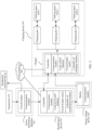
- FIG. 3 is a schematic diagram of a structure of a charging system according to an embodiment of this application.
- the charging system may be used in a campus.
- the charging system includes a transformer 301, a power distribution apparatus 302, a rectification device 303, an energy storage device 304, and a charging device 305 that are deployed in the campus.
- the transformer 301 is connected to the power distribution apparatus 302.
- the power distribution apparatus 302 is connected to the rectification device 303.
- the rectification device 303 is connected to the energy storage device 304 and the charging device 305.
- the transformer 301 may be configured to supply power to the power distribution apparatus 302.
- the transformer is connected to a power grid, and is configured to receive an alternating-current voltage provided by the power grid, and perform buck conversion on the alternating-current voltage.
- a voltage obtained through buck conversion may be used to supply power to the power distribution apparatus 302.
- the transformer is connected to a 10 kV power grid, and is configured to convert a 10 kV alternating-current voltage into a 400 V alternating-current voltage.
- the 400 V alternating-current voltage may be used to supply power to the power distribution apparatus 302.
- the power distribution apparatus 302 may be configured to supply power to a load, obtain information about the load, and so on.
- the load may include a residential electrical device and the rectification device 303.
- the power distribution apparatus 301 may include a circuit breaker and a communication module.
- the circuit breaker is configured to receive an alternating-current voltage provided by the transformer 301, and supply power to the residential electrical device and/or the rectification device 303 based on the alternating-current voltage.
- the circuit breaker may be further configured to obtain electricity consumption load information of the residential electrical device.
- the communication module may be configured to support the power distribution apparatus 302 in communication, for example, support the power distribution apparatus 302 in communicating with the rectification device 303 through Ethernet, a controller area network (controller area network, CAN), or a 4G network.
- the rectification device 303 may be configured to convert an alternating-current voltage into a direct-current voltage, control the energy storage device 304 and the charging device 305, detect a power of the energy storage device 304, communicate with the power distribution apparatus 302 and the charging device 305, and so on.
- the rectification device 303 may include a plurality of rectification modules, a circuit breaker matrix, a local power grid database, a communication module, and a controller. Each of the plurality of rectification modules may be configured to implement the conversion from an alternating-current voltage into a direct-current voltage.
- the circuit breaker matrix includes a plurality of circuit breakers, and each circuit breaker may be configured to turn on or turn off one or more of the plurality of rectification modules.
- the communication module may be configured to support the rectification device 303 in communicating with a cloud platform, the power distribution apparatus 302, and the charging device 305.
- the communication module may be configured to support the rectification device 303 in receiving the electricity consumption load information of the residential electrical device that is sent by the power distribution apparatus 302.
- the local power grid database may be configured to store the electricity consumption load information.
- the controller may be configured to control one or more circuit breakers in the circuit breaker matrix to be switched on or switched off, control the energy storage device 304 to start or stop, detect a power of the energy storage device 304, and so on.
- the energy storage device 304 may be configured to receive a direct-current voltage provided by the rectification device 303, and store energy based on the direct-current voltage.
- the energy storage device 304 may be further configured to supply power to the charging device 305.
- the energy storage device 304 may include a battery and a communication module.
- the battery may be configured to store the energy.
- the communication module may be configured to support the energy storage device 304 in communicating with the rectification device 303.
- the charging device 305 may include a charger and a plurality of charging piles.
- the charger may be configured to implement buck conversion of a direct-current voltage, control the plurality of charging piles to be turned off or turned on, adjust output powers of the plurality of charging piles, and so on.
- the charger includes a plurality of charging modules, a circuit breaker matrix, a local vehicle database, a controller, and a communication module.
- Each of the plurality of charging modules may be configured to implement the buck conversion function.
- the circuit breaker matrix includes a plurality of circuit breakers, and each circuit breaker may be configured to turn on or turn off one or more of the plurality of charging modules.
- the communication module may be configured to support the charger in communicating with the rectification device 303.
- the controller may be configured to control one or more circuit breakers in the circuit breaker matrix to be switched on or switched off, control the plurality of charging piles to be turned off or turned on, and adjust output powers of the plurality of charging piles.
- the local vehicle database may be configured to store battery charging curves corresponding to different vehicle models, and the battery charging curves may be used to indicate optimal charging powers corresponding to different battery levels.
- the charging device 305 may further include a plurality of parking space locks.
- Each of the parking space locks corresponds to one charging pile, and the charging pile may be configured to control the corresponding parking space lock to be enabled or disabled, and so on.
- the charging pile may enable a corresponding parking space lock; or when a charging pile is idle, the charging pile may disable a corresponding parking space lock.
- the charging system may further include a cloud platform 306.
- the cloud platform 306 may be configured to receive related electricity consumption information sent by the rectification device 303 and the charging device 305, and perform analysis, statistics collection, storage, and the like based on the related information.
- the related electricity consumption information may include electricity consumption load of a residential electrical device in the campus in different time periods, and battery charging curves corresponding to different vehicle models.
- FIG. 4 is a schematic flowchart of a charging control method according to an embodiment of this application. As shown in FIG. 4 , the charging control method includes the following steps.
- a charger detects that a first vehicle is connected to a first charging pile, and sends first information to a rectification device, where the first information is used to indicate that the first charging pile is to charge the first vehicle.
- the charger is connected to a plurality of charging piles, and the first charging pile may be any one of the plurality of charging piles.
- the plurality of charging piles may include 10 charging piles and may be denoted as C1 to C10.
- the first charging pile may be any one of the 10 charging piles, and the first charging pile may be C1 or C4.
- the first information may include vehicle information of the first vehicle, charging information of the charger, information about the first charging pile, and the like.
- vehicle information may include a vehicle model, a remaining electricity quantity, a battery charging curve, and the like of the first vehicle;
- the charging information of the charger may include a remaining charging power of the charger, and the like;
- the information about the first charging pile may include an identifier of the first charging pile.
- the charger may further obtain service information of the first vehicle, and send the service information to the rectification device.
- the service information may include the vehicle information of the first vehicle.
- the service information may further include user information.
- the user information may include an identifier of a user who needs to charge the first vehicle, and payment information bound to the user identifier.
- the charger may separately send the first information and the service information to the rectification device through two times of sending, or may send the first information and the service information to the rectification device through one time of sending. This is not specifically limited in this embodiment of this application.
- the rectification device receives the first information from the charger, where the first information is used to indicate that the first charging pile is to charge the first vehicle.
- the rectification device may further receive the service information.
- the rectification device obtains electricity consumption load of a campus, where the electricity consumption load of the campus is electricity consumption load of a campus in which the rectification device and the charger are located.
- the electricity consumption load of the campus may also be referred to as an electricity consumption power of the campus.
- Electricity consumption of the campus may include electricity consumption of the rectification device and electricity consumption of a residential electrical device in the campus.
- the electricity consumption of the residential electrical device in the campus may include electricity consumption of a device other than the rectification device in the campus.
- the electricity consumption load of the campus is electricity consumption load of the residential electrical device in the campus.
- the rectification device receives indication information from a power distribution apparatus, where the indication information is used to indicate the electricity consumption load of the campus, so that the rectification device may determine the electricity consumption load of the campus according to the indication information.
- the power distribution apparatus may be configured to obtain electricity consumption load information of an electrical device in the campus at different moments, and send the electricity consumption load information to the rectification device. For example, the power distribution apparatus may periodically obtain the electricity consumption load information, and send the electricity consumption load information to the rectification device after obtaining the electricity consumption load information each time.
- the rectification device may obtain, through comparison, a magnitude relationship between the electricity consumption load of the campus and at least one load threshold, where the at least one load threshold may include one or more preset load thresholds.
- the at least one load threshold includes a first load threshold and a second load threshold and the first load threshold is greater than the second load threshold is used for description below.
- S404a If the electricity consumption load of the campus is greater than the first load threshold, the rectification device sends second information to the charger, where the second information is used to indicate that an energy storage device is to supply power to the charger.
- the first load threshold is a load value when electricity consumption of the electrical device in the campus is at a load peak, namely, a power value when an electricity consumption power of the electrical device in the campus reaches a maximum value.
- the first load threshold may also be referred to as a peak load value.
- the first load threshold may be stored on the rectification device.
- the first load threshold may be stored in a local power grid database on the rectification device.
- the first load threshold may be a value calculated by the rectification device based on a power of a transformer and a peak-hour electricity consumption coefficient (to be specific, an electricity consumption coefficient during peak hours of electricity consumption load) of the electrical device in the campus.
- the peak-hour electricity consumption coefficient is a peak value of annual electricity consumption load of the electrical device in the campus, and may be specifically calculated based on daily electricity consumption load of the electrical device in the campus. For example, a peak value of daily electricity consumption load is calculated based on the daily electricity consumption load of the electrical device in the campus, and then the peak value of annual electricity consumption load of the electrical device in the campus is calculated based on peak values of daily electricity consumption load within a year.
- the rectification device compares the electricity consumption load of the campus with the first load threshold. If the electricity consumption load of the campus is greater than the first load threshold, it indicates that the electricity consumption load of the campus is at a load peak. Therefore, the rectification device may send the second information to the charger, where the second information is used to indicate that the energy storage device is to supply power to the charger. Further, the rectification device may further control the energy storage device to start, so that the energy storage device supplies power to the charger.
- the rectification device may further send charging indication information to the charger, where the charging indication information is used to indicate a charging power used by the first charging pile to charge the first vehicle.
- the rectification device may determine the charging indication information based on the service information and the first information, for example, determine the charging indication information based on information such as the battery charging curve of the first vehicle, the remaining charging power of the charger, and the remaining electricity quantity of the first vehicle.
- the charger receives the second information from the rectification device, where the second information is used to indicate that the energy storage device is to supply power to the charger.
- the charger may further receive the charging indication information from the rectification device, where the charging indication information is used to indicate the charging power used by the first charging pile to charge the first vehicle.
- the charger receives electric energy provided by the energy storage device, and controls the first charging pile to charge the first vehicle.
- the charger when the charger receives the electric energy provided by the energy storage device, the charger may control or adjust a charging power of the first charging pile based on the remaining electricity quantity of the first vehicle, the battery charging curve of the first vehicle, and the remaining charging power of the charger, to charge the first vehicle, where the charging power of the first charging pile is an optimal charging power that adapts to the first vehicle.
- the battery charging curve of the first vehicle indicates optimal charging powers of a battery at different battery levels.
- the charger may locally obtain the battery charging curve of the first vehicle.
- the battery charging curve is pre-stored in a local vehicle database of the charger, the local vehicle database may include battery charging curves corresponding to different vehicle models, and the charger may obtain the battery charging curve from the local vehicle database of the charger based on the vehicle model of the first vehicle.
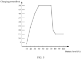
- FIG. 5 is a schematic diagram of the battery charging curve corresponding to the vehicle model of the first vehicle.
- the charging power of the first vehicle when a battery level of the first vehicle is 10%, the charging power of the first vehicle is 3 kW; when a battery level of the first vehicle is 20%, the charging power of the first vehicle is 23 kW; when a battery level of the first vehicle is 30%, the charging power of the first vehicle is 40 kW; when a battery level of the first vehicle is 40% to 70%, the charging power of the first vehicle is 50 kW; when a battery level of the first vehicle is 75%, the charging power of the first vehicle is 20 kW; or when a battery level of the first vehicle is 80% to 100%, the charging power of the first vehicle is 15 kW.
- the charging power corresponding to the battery charging curve of the first vehicle is 40 kW.
- the charger receives the electric energy provided by the energy storage device, and charges the first vehicle at a power of 30 kW; or if the remaining power of the charger is 50 kW, the charger receives the electric energy provided by the energy storage device, and charges the first vehicle at a power of 40 kW.
- the charger when the charger further receives the charging indication information from the rectification device, when receiving the electric energy provided by the energy storage device, the charger may control or adjust a charging power of the first charging pile directly based on the charging indication information, to charge the first vehicle, where the charging power of the first charging pile is an optimal charging power that adapts to the first vehicle.
- FIG. 4 shows a case in which the electricity consumption load of the campus is greater than the first load threshold.
- FIG. 6 shows that the electricity consumption load of the campus is less than the second load threshold.
- the method further includes the following steps.
- the rectification device If the electricity consumption load of the campus is less than the second load threshold, the rectification device sends third information to the charger, where the third information is used to indicate that the rectification device is to supply power to the charger.
- the second load threshold is a load value when electricity consumption of the electrical device in the campus is at a load trough, namely, a power value when an electricity consumption power of the electrical device in the campus reaches a minimum value.
- the second load threshold may also be referred to as a trough load value.
- the second load threshold may be stored on the rectification device.
- the second load threshold may be stored in a local power grid database on the rectification device.
- the second load threshold may be a value calculated by the rectification device based on a power of a transformer and an off-peak-hour electricity consumption coefficient (to be specific, an electricity consumption coefficient during off-peak hours of electricity consumption load) of the electrical device in the campus.
- the off-peak-hour electricity consumption coefficient is a trough value of annual electricity consumption load of the electrical device in the campus, and may be specifically calculated based on daily electricity consumption load of the electrical device in the campus. For example, a trough value of daily electricity consumption load is calculated based on the daily electricity consumption load of the electrical device in the campus, and then the trough value of annual electricity consumption load of the electrical device in the campus is calculated based on trough values of daily electricity consumption load within a year.
- the second load threshold is less than the first load threshold. For example, if the second load threshold is A and the first load threshold is B, A is less than B.
- the rectification device compares the electricity consumption load of the campus with the second load threshold. If the electricity consumption load of the campus is less than the second load threshold, it indicates that the electricity consumption load of the campus is at a load trough. Therefore, the rectification device may send the third information to the charger, where the third information is used to indicate that the rectification device is to supply power to the charger.
- the rectification device charges the energy storage device.
- the rectification device may control the energy storage device to start, and the energy storage device receives electric energy provided by the rectification device, and stores the electric energy.
- the rectification device may further obtain electricity quantity information of the energy storage device.
- the electricity quantity information may be used to indicate a battery level of the energy storage device.
- the rectification device may determine, based on the electricity quantity information, whether to continue to charge the energy storage device. For example, if the battery level of the energy storage device is less than a rated electricity quantity of the energy storage device, the rectification device continues to charge the energy storage device; or if the battery level of the energy storage device is equal to the rated electricity quantity of the energy storage device, the rectification device no longer charges the energy storage device.
- S405b The charger receives the third information from the rectification device, where the third information is used to indicate that the rectification device is to supply power to the charger.
- the charger receives electric energy provided by the rectification device, and controls the first charging pile to supply power to charge the first vehicle.
- a process of controlling, by the charger, the first charging pile to supply power to charge the first vehicle is the same as the charging process in S406a. For details, refer to the charging process in S406. Details are not described herein again.
- FIG. 6 shows a case in which the electricity consumption load of the campus is less than the second load threshold.
- FIG. 7 shows that the electricity consumption load of the campus is less than or equal to the first load threshold and is greater than or equal to the second load threshold.
- the method further includes the following steps.
- the rectification device sends fourth information to the charger, where the fourth information is used to indicate that the rectification device and/or the energy storage device are/is to supply power to the charger.
- the electricity consumption load of the campus is compared with the first load threshold and the second load threshold. If the electricity consumption load of the campus is less than or equal to the first load threshold and is greater than or equal to the second load threshold, it indicates that the electricity consumption load of the campus is greater than a load trough and is less than a load peak, in other words, the electricity consumption load of the campus is in a middle stage of load.
- the rectification device may send the fourth information to the charger, where the fourth information is used to indicate that the rectification device is to supply power to the charger.
- the rectification device may send the fourth information to the charger, where the fourth information is used to indicate that the rectification device and the energy storage device are to supply power to the charger. Further, the rectification device may further control the energy storage device to start, so that the energy storage device supplies power to the charger.
- the charger receives the fourth information from the rectification device, where the fourth information is used to indicate that the rectification device and/or the energy storage device are/is to supply power to the charger.
- the charger receives electric energy provided by the rectification device and/or the energy storage device, and controls the first charging pile to charge the first vehicle.
- a process of controlling, by the charger, the first charging pile to supply power to charge the first vehicle is the same as the charging process in S406a. For details, refer to the charging process in S406a. Details are not described herein again.
- the user information sent by the charger to the rectification device further includes at least one of the following: a user level and specified charging duration.
- the rectification device may directly send fifth information to the charger, where the fifth information is used to indicate that the rectification device is to supply power to the charger.
- the charger may receive the fifth information sent by the rectification device, and after receiving the fifth information, receive electric energy provided by the energy storage device, and control the first charging pile to charge the first vehicle.
- the charger receives the electric energy provided by the energy storage device, and controls the first charging pile to charge the first vehicle. In this process, a charging requirement of an electric vehicle is met, and charging experience of an electric vehicle user is also improved.
- the rectification device may further determine the charging indication information comprehensively based on the specified charging duration and other information in the service information sent by the charger. For example, if duration of the specified charging duration is less than preset duration, the rectification device may increase a charging power indicated in the charging indication information; or if duration of the specified charging duration is greater than preset duration, the rectification device may reduce a charging power indicated in the charging indication information. In this process, a charging requirement of an electric vehicle is met, and a requirement of an electric vehicle user is also met, thereby improving charging experience of the electric vehicle user.
- the electricity consumption load of the campus is at a load peak, and the rectification device controls the energy storage device to supply power to the charger.
- This can meet a charging requirement of an electric vehicle, and also reduce impact of charging of the electric vehicle on a power grid during peak hours of load, thereby relieving a burden of the power grid.
- this improves charging experience of an electric vehicle user compared with the manner in FIG. 1 in which the charging pile power control unit turns off the charging pile or reduces the output power of the charging pile.
- the electricity consumption load of the campus is at a load trough, and the rectification device supplies power to the charger, and charges the energy storage device.
- This meets a charging requirement of an electric vehicle, and also stores electric energy at the load trough, to supply power to the charger when the electricity consumption load of the campus is at a load peak.
- an electricity price at the load trough is lower than that at the load peak in the campus, thereby reducing electricity consumption costs.
- the electricity consumption load of the campus is greater than a load trough and is less than a load peak, the rectification device and/or the energy storage device supply/supplies power to the charger. This meets a charging requirement of an electric vehicle, and also fully utilizes a power distribution capacity of the campus, thereby reducing an unnecessary increase in the power distribution capacity of the campus.
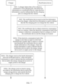
- the method includes: S1: A charger obtains information about an available charging power of the charger. S2: The charger determines whether a first vehicle is connected to a first charging pile. If no first vehicle is connected to the first charging pile (namely, N), S2 is performed again; or if a first vehicle is connected to the first charging pile (namely, Y), S3 is performed. S3: The charger obtains service information of the first vehicle. S4: The charger determines whether a user level of the first vehicle is a specified user level.
- a rectification device supplies power to the charger; or if the user level is not the specified user level (namely, N), the charger sends first information to the rectification device.
- S5 When the rectification device receives the first information, the rectification device obtains electricity consumption load of a campus.
- S7 The rectification device determines whether the electricity consumption load of the campus is less than a second load threshold. If the electricity consumption load of the campus is less than the second load threshold (namely, Y), the rectification device supplies power to the charger and performs S8.
- S8 The rectification device charges the energy storage device.
- S9 The rectification device determines whether a battery of the energy storage device is fully charged. If the battery of the energy storage device is not fully charged (namely, N), the rectification device continues to perform S7; or if the battery of the energy storage device is fully charged (namely, Y), S10 is performed.
- S10 The rectification device indicates the energy storage device to wait for power supply.
- S11 If the electricity consumption load of the campus is greater than the second load threshold (namely, N) in S7, S11 is performed.
- S11 If the electricity consumption load of the campus is greater than or equal to the second threshold and is less than or equal to the first threshold, the rectification device and/or the energy storage device supply/supplies power to the charger. In S4, S6, S7, and S11, after receiving electric energy, the charger charges the first vehicle at an optimal power that adapts to a battery charging curve.
- the charger and the rectification device include corresponding hardware structures and/or software modules for performing the functions.
- a person of ordinary skill in the art should easily be aware that, in combination with algorithms and steps in the examples described in embodiments disclosed in this specification, this application can be implemented by hardware or a combination of hardware and computer software. Whether a function is performed by hardware or hardware driven by computer software depends on particular applications and design constraints of the technical solutions. A person skilled in the art may use different methods to implement the described functions for each particular application, but it should not be considered that the implementation goes beyond the scope of this application.
- functional modules of the charger and the rectification device may be obtained through division based on the foregoing method examples.
- the functional modules may be obtained through division based on the corresponding functions, or at least two functions may be integrated in one processing module.
- the integrated module may be implemented in a form of hardware, or may be implemented in a form of a software functional module. It should be noted that, in this embodiment of this application, module division is exemplary, and is merely a logical function division. In actual implementation, another division manner may be used.
- FIG. 9 is a schematic diagram of a possible structure of the charger in the foregoing embodiments.
- the charger includes a detection unit 901, a first sending unit 902, a first receiving unit 903, and a control unit 904.
- the detection unit 901 and the first sending unit 902 are configured to support the charger in performing S401 in the foregoing method embodiments.
- the first receiving unit 903 is configured to support the charger in performing one or more steps of S405a, S405b, S405c, S406a, S406b, and S406c in the foregoing method embodiments.
- the control unit 904 is configured to support the charger in performing one or more steps of S406a, S406b, and S406c in the foregoing method embodiments.
- the charger further includes a first obtaining unit 905.
- the first obtaining unit 905 is configured to obtain service information, where the service information includes user information and vehicle information of the first vehicle.
- FIG. 10 is a schematic diagram of a possible structure of the rectification device in the foregoing embodiments.
- the rectification device includes a second receiving unit 101, a second obtaining unit 102, a comparison unit 103, and a second sending unit 104.
- the second receiving unit 101 is configured to support the rectification device in performing S402 in the foregoing method embodiments.
- the second obtaining unit 102 is configured to support the rectification device in performing S403 in the foregoing method embodiments.
- the comparison unit 103 and the second sending unit 104 are configured to support the rectification device in performing S404a, S404b, and S404c in the foregoing method embodiments.
- the rectification device further includes a charging unit 105, and the charging unit 105 is configured to charge the energy storage device.
- FIG. 11 is a schematic diagram of another possible structure of the charger in the foregoing embodiments according to an embodiment of this application.
- the charger includes a processor 01 and a memory 02, and the memory 02 is configured to store code and data of the charger.
- the processor 01 is configured to control and manage an action of the charger.
- the processor 01 is configured to support the charger in performing S401, S405a, S405b, S405c, S406a, S406b, and S406c in the foregoing method embodiments, and/or is used for other processes of the technology described in this specification.
- the processor 01 may be a central processing unit, a general-purpose processor, a digital signal processor, an application-specific integrated circuit, a field programmable gate array or another programmable logical device, a transistor logical device, a hardware component, or any combination thereof.
- the processor 01 may implement or execute various example logical blocks, modules, and circuits described with reference to content disclosed in this application.
- the processor 01 may be a combination of processors implementing a computing function, for example, a combination of one or more microprocessors, or a combination of the digital signal processor and a microprocessor.
- FIG. 12 is a schematic diagram of another possible structure of the rectification device in the foregoing embodiments according to an embodiment of this application.
- the charger includes a processor 03 and a memory 04, and the memory 04 is configured to store code and data of the charger.
- the processor 03 is configured to control and manage an action of the charger.
- the processor 03 is configured to support the charger in performing S402, S403, S404a, S404b, and S404c in the foregoing method embodiments, and/or is used for other processes of the technology described in this specification.
- the processor 03 may be a central processing unit, a general-purpose processor, a digital signal processor, an application-specific integrated circuit, a field programmable gate array or another programmable logical device, a transistor logical device, a hardware component, or any combination thereof.
- the processor 03 may implement or execute various example logical blocks, modules, and circuits described with reference to content disclosed in this application.
- the processor 03 may be a combination of processors implementing a computing function, for example, a combination of one or more microprocessors, or a combination of the digital signal processor and a microprocessor.
- an embodiment of this application further provides a charging system.
- the charging system includes a rectification device, an energy storage device, a charger, and a plurality of charging piles.
- the rectification device is connected to the charger and the energy storage device.
- the charger is connected to the energy storage device and the plurality of charging piles.
- the charger includes the charger provided in FIG. 9 .
- the rectification device includes the rectification device provided in FIG. 10 .
- the disclosed device and method may be implemented in other manners.
- the described device embodiment is merely an example.
- the module and division into the units is merely logical function division and may be other division in actual implementation.
- a plurality of units or components may be combined or integrated into another system, or some features may be ignored or not performed.
- functional units in embodiments of this application may be integrated into one processing unit, or each of the units may exist alone physically, or two or more units are integrated into one unit.
- the integrated unit may be implemented in a form of hardware, or may be implemented in a form of a software functional unit.
- the integrated unit When the integrated unit is implemented in the form of a software functional unit and sold or used as an independent product, the integrated unit may be stored in a readable storage medium.
- the technical solutions in embodiments of this application essentially, or the part contributing to the conventional technology, or all or some of the technical solutions may be implemented in a form of a software product.
- the software product is stored in a storage medium and includes several instructions for enabling an apparatus to perform all or some of the steps of the methods described in embodiments of this application.
- the foregoing storage medium includes any medium that can store program code, such as a USB flash drive, a removable hard disk, a ROM, a RAM, a magnetic disk, or an optical disc.
Landscapes
- Engineering & Computer Science (AREA)
- Power Engineering (AREA)
- Transportation (AREA)
- Mechanical Engineering (AREA)
- Charge And Discharge Circuits For Batteries Or The Like (AREA)
Claims (6)
- Ladesteuerverfahren, das auf eine Gleichrichtungsvorrichtung (303) angewandt wird, wobei das Verfahren Folgendes umfasst:Empfangen von ersten Informationen von einem Ladegerät durch die Gleichrichtungsvorrichtung (303), wobei die ersten Informationen verwendet werden, um anzugeben, dass eine erste Ladesäule ein erstes Fahrzeug aufladen soll, und wobei eine Ladevorrichtung (305) das Ladegerät umfasst und wobei die Gleichrichtungsvorrichtung (303) mit der Ladevorrichtung (305) verbunden ist;Erhalten von Elektrizitätsverbrauchslast eines Geländes durch die Gleichrichtungsvorrichtung (303), wobei die Elektrizitätsverbrauchslast des Geländes die Elektrizitätsverbrauchslast eines Geländes ist, in dem sich die Gleichrichtungsvorrichtung (303) und das Ladegerät befinden;wenn die Elektrizitätsverbrauchslast des Geländes größer als eine erste Lastschwelle ist, Senden von zweiten Informationen zu dem Ladegerät durch die Gleichrichtungsvorrichtung (303), wobei die zweiten Informationen verwendet werden, um anzugeben, dass eine Energiespeichervorrichtung (304) dem Ladegerät Strom liefern soll;Steuern der Energiespeichervorrichtung (304) zum Starten durch die Gleichrichtungsvorrichtung (303), sodass die Energiespeichervorrichtung (304) dem Ladegerät Strom liefert;wenn die Elektrizitätsverbrauchslast des Geländes kleiner oder gleich der ersten Lastschwelle ist und größer oder gleich einer zweiten Lastschwelle ist, und wenn die Leistung der Gleichrichtungsvorrichtung (303) kleiner als die zum Laden des ersten Fahrzeugs erforderliche Leistung ist, sendet die Gleichrichtungsvorrichtung (303) vierte Informationen zu dem Ladegerät, wobei die vierten Informationen verwendet werden, um anzugeben, dass die Gleichrichtungsvorrichtung (303) und die Energiespeichervorrichtung (305) dem Ladegerät Strom liefern sollen,wobei, dass die Elektrizitätsverbrauchslast des Geländes kleiner oder gleich der ersten Lastschwelle ist und größer oder gleich der zweiten Lastschwelle ist, angibt, dass die Elektrizitätsverbrauchslast des Geländes größer als eine Lastmulde und kleiner als eine Lastspitze ist, undwobei die Gleichrichtungsvorrichtung (303) ausgelegt ist zum Umwandeln einer Wechselspannung in eine Gleichspannung, Steuern der Energiespeichervorrichtung (304) und der Ladevorrichtung (305), Erkennen einer Leistung der Energiespeichervorrichtung (304) und Kommunizieren mit einer Stromverteilungsvorrichtung (302) und der Ladevorrichtung (305).
- Verfahren nach Anspruch 1, wobei das Verfahren ferner Folgendes umfasst:
wenn die Elektrizitätsverbrauchslast des Geländes kleiner als eine zweite Lastschwelle ist, Senden von dritten Informationen zu dem Ladegerät durch die Gleichrichtungsvorrichtung (303), wobei die dritten Informationen verwendet werden, um anzugeben, dass die Gleichrichtungsvorrichtung (303) dem Ladegerät Strom liefern soll, und die zweite Lastschwelle kleiner als die erste Lastschwelle ist. - Verfahren nach Anspruch 1 oder 2, wobei die Gleichrichtungsvorrichtung (303) mit der Energiespeichervorrichtung (304) verbunden ist und das Verfahren ferner Folgendes umfasst:
wenn die Elektrizitätsverbrauchslast des Geländes kleiner als die zweite Lastschwelle ist, Laden der Energiespeichervorrichtung (304) durch die Gleichrichtungsvorrichtung (303). - Gleichrichtungsvorrichtung, wobei die Gleichrichtungsvorrichtung Folgendes umfasst:eine zweite Empfangseinheit (101), ausgelegt zum Empfangen von ersten Informationen von einem Ladegerät, wobei die ersten Informationen verwendet werden, um anzugeben, dass eine erste Ladesäule ein erstes Fahrzeug aufladen soll,eine zweite Erhalteeinheit (102), ausgelegt zum Erhalten von Elektrizitätsverbrauchslast des Geländes, wobei die Elektrizitätsverbrauchslast des Geländes die Elektrizitätsverbrauchslast eines Geländes ist, in dem sich die Gleichrichtungsvorrichtung (303) und das Ladegerät befinden;eine Vergleichseinheit (103), ausgelegt zum Vergleichen der Elektrizitätsverbrauchslast des Geländes mit einer ersten Lastschwelle; undeine zweite Sendeeinheit (104), ausgelegt zum Senden von zweiten Informationen zu dem Ladegerät, wenn die Elektrizitätsverbrauchslast des Geländes größer als die erste Lastschwelle ist, wobei die zweiten Informationen verwendet werden, um anzugeben, dass eine Energiespeichervorrichtung (304) dem Ladegerät Strom liefern soll,wobei die Vergleichseinheit (103) ferner ausgelegt ist zumVergleichen der Elektrizitätsverbrauchslast des Geländes mit einer zweiten Lastschwelle,wenn die Elektrizitätsverbrauchslast des Geländes kleiner oder gleich der ersten Lastschwelle ist und größer oder gleich einer zweiten Lastschwelle ist, und wenn die Leistung der Gleichrichtungsvorrichtung kleiner als die zum Laden des ersten Fahrzeugs erforderliche Leistung ist, ist die zweite Sendeeinheit (104) ferner ausgelegt zum Senden von vierten Informationen zu dem Ladegerät, wobei die vierten Informationen verwendet werden, um anzugeben, dass die Gleichrichtungsvorrichtung (303) und die Energiespeichervorrichtung (305) dem Ladegerät Strom liefern sollen, und wobei, dass die Elektrizitätsverbrauchslast des Geländes kleiner oder gleich der ersten Lastschwelle ist und größer oder gleich der zweiten Lastschwelle ist, angibt, dass die Elektrizitätsverbrauchslast des Geländes größer als eine Lastmulde und kleiner als eine Lastspitze ist.
- Gleichrichtungsvorrichtung nach Anspruch 4, wobei die Vergleichseinheit (103) ferner ausgelegt ist zumVergleichen der Elektrizitätsverbrauchslast des Geländes mit der zweiten Lastschwelle,wenn die Elektrizitätsverbrauchslast des Geländes kleiner als die zweite Lastschwelle ist, ist die zweite Sendeeinheit (104) ferner ausgelegt zum Senden von dritten Informationen zu dem Ladegerät, wobei die dritten Informationen verwendet werden, um anzugeben, dass die Gleichrichtungsvorrichtung (303) dem Ladegerät Strom liefern soll, und die zweite Lastschwelle kleiner als die erste Lastschwelle ist.
- Ladesystem, wobei das Ladesystem eine Gleichrichtungsvorrichtung (303), eine Energiespeichervorrichtung (304), eine Ladevorrichtung (305) und ein Ladegerät umfasst; die Gleichrichtungsvorrichtung (303), die Energiespeichervorrichtung (305) und die Ladevorrichtung (305) miteinander verbunden sind; und die Gleichrichtungsvorrichtung (303) die Gleichrichtungsvorrichtung (303) nach einem der Ansprüche 4 oder 5 umfasst.
Priority Applications (1)
| Application Number | Priority Date | Filing Date | Title |
|---|---|---|---|
| EP24192466.1A EP4492603A3 (de) | 2021-07-31 | 2022-07-29 | Ladesteuerungsverfahren, ladesystem und entsprechende vorrichtung |
Applications Claiming Priority (1)
| Application Number | Priority Date | Filing Date | Title |
|---|---|---|---|
| CN202110877365.2A CN114290936B (zh) | 2021-07-31 | 2021-07-31 | 一种充电控制方法、充电系统及相关设备 |
Related Child Applications (1)
| Application Number | Title | Priority Date | Filing Date |
|---|---|---|---|
| EP24192466.1A Division EP4492603A3 (de) | 2021-07-31 | 2022-07-29 | Ladesteuerungsverfahren, ladesystem und entsprechende vorrichtung |
Publications (2)
| Publication Number | Publication Date |
|---|---|
| EP4124500A1 EP4124500A1 (de) | 2023-02-01 |
| EP4124500B1 true EP4124500B1 (de) | 2024-08-28 |
Family
ID=80964082
Family Applications (2)
| Application Number | Title | Priority Date | Filing Date |
|---|---|---|---|
| EP22187968.7A Active EP4124500B1 (de) | 2021-07-31 | 2022-07-29 | Ladesteuerungsverfahren, ladesystem und entsprechende vorrichtung |
| EP24192466.1A Pending EP4492603A3 (de) | 2021-07-31 | 2022-07-29 | Ladesteuerungsverfahren, ladesystem und entsprechende vorrichtung |
Family Applications After (1)
| Application Number | Title | Priority Date | Filing Date |
|---|---|---|---|
| EP24192466.1A Pending EP4492603A3 (de) | 2021-07-31 | 2022-07-29 | Ladesteuerungsverfahren, ladesystem und entsprechende vorrichtung |
Country Status (2)
| Country | Link |
|---|---|
| EP (2) | EP4124500B1 (de) |
| CN (2) | CN114290936B (de) |
Families Citing this family (5)
| Publication number | Priority date | Publication date | Assignee | Title |
|---|---|---|---|---|
| CN116311683B (zh) * | 2023-04-04 | 2025-02-18 | 广东力盾新能源科技有限公司 | 共享充电桩计费方法、装置、电子设备及存储介质 |
| CN116766984A (zh) * | 2023-06-21 | 2023-09-19 | 重庆赛迪奇智人工智能科技有限公司 | 一种车辆充电装置、方法、系统及车辆 |
| CN116923162B (zh) * | 2023-09-18 | 2023-12-12 | 杭州格创新能源有限公司 | 基于区块链定制化数据同步电动汽车有序充电方法及设备 |
| CN117681717A (zh) * | 2023-11-15 | 2024-03-12 | 华为数字能源技术有限公司 | 充电设备和功率分配装置 |
| CN117799483B (zh) * | 2024-03-01 | 2024-06-21 | 杭州仓信电力科技有限公司 | 利用类型解析的智能充电桩电量调配系统 |
Citations (1)
| Publication number | Priority date | Publication date | Assignee | Title |
|---|---|---|---|---|
| CN110601334A (zh) * | 2019-08-07 | 2019-12-20 | 许继电源有限公司 | 一种充电站及其能量调度管理方法 |
Family Cites Families (9)
| Publication number | Priority date | Publication date | Assignee | Title |
|---|---|---|---|---|
| US8872379B2 (en) * | 2007-11-30 | 2014-10-28 | Johnson Controls Technology Company | Efficient usage, storage, and sharing of energy in buildings, vehicles, and equipment |
| US8294420B2 (en) * | 2009-09-29 | 2012-10-23 | Schneider Electric USA, Inc. | Kiosk vehicle charging and selecting systems |
| CN105576809A (zh) * | 2016-03-08 | 2016-05-11 | 中国矿业大学 | 一种基于风光柴储微网的双向充电桩系统 |
| CN106828170B (zh) * | 2017-03-07 | 2019-11-08 | 广州灿明都科技有限责任公司 | 防逆流控制系统及方法 |
| CN206781555U (zh) * | 2017-04-26 | 2017-12-22 | 天津市三源电力设备制造有限公司 | 一种功率可调控的交流充电桩系统 |
| CN107719164B (zh) * | 2017-10-11 | 2020-02-18 | 华北电力大学 | 基于topsis排序的居民区电动汽车有序充电方法 |
| CN110682823A (zh) * | 2018-07-05 | 2020-01-14 | 邬超慧 | 一种电动汽车充电控制方法及系统 |
| CN112757952B (zh) * | 2018-08-09 | 2023-01-17 | 西安艾润物联网技术服务有限责任公司 | 一种车辆充电方法、装置及系统 |
| CN111347915A (zh) * | 2020-03-20 | 2020-06-30 | 重庆工业职业技术学院 | 基于社区配电网变压器负载的纯电动汽车充电方法与装置 |
-
2021
- 2021-07-31 CN CN202110877365.2A patent/CN114290936B/zh active Active
- 2021-07-31 CN CN202410246889.5A patent/CN118082590A/zh active Pending
-
2022
- 2022-07-29 EP EP22187968.7A patent/EP4124500B1/de active Active
- 2022-07-29 EP EP24192466.1A patent/EP4492603A3/de active Pending
Patent Citations (1)
| Publication number | Priority date | Publication date | Assignee | Title |
|---|---|---|---|---|
| CN110601334A (zh) * | 2019-08-07 | 2019-12-20 | 许继电源有限公司 | 一种充电站及其能量调度管理方法 |
Also Published As
| Publication number | Publication date |
|---|---|
| CN118082590A (zh) | 2024-05-28 |
| CN114290936B (zh) | 2024-03-26 |
| EP4124500A1 (de) | 2023-02-01 |
| CN114290936A (zh) | 2022-04-08 |
| EP4492603A2 (de) | 2025-01-15 |
| EP4492603A3 (de) | 2025-03-05 |
Similar Documents
| Publication | Publication Date | Title |
|---|---|---|
| EP4124500B1 (de) | Ladesteuerungsverfahren, ladesystem und entsprechende vorrichtung | |
| US10663932B2 (en) | Grid regulation services for energy storage devices based on grid frequency | |
| CN108964007B (zh) | 一种直流配电方法、装置及系统 | |
| CN110661278B (zh) | 储能空调系统及其控制方法和控制装置 | |
| EP2842792A1 (de) | Verfahren zum Aufladen eines Akkumulators eines elektrischen Fahrzeugs | |
| CN108604820B (zh) | 管理装置和控制方法 | |
| EP3024115A1 (de) | Schnelles ladeverfahren für speicherzellen, schnelles ladesystem und programm | |
| US10369895B2 (en) | Power supply controller | |
| CN106026151B (zh) | 一种电动车储换电站的调度方法及装置 | |
| JP5165042B2 (ja) | 系統電力安定化システム、系統電力安定化方法、及び充放電器 | |
| CN111301219A (zh) | 一种电动车电池控制方法、系统、设备及可读存储介质 | |
| US20250004059A1 (en) | Battery capacity estimation device, charging plan generation device, discharging plan generation device, and battery capacity estimation method | |
| CN117955140B (zh) | 功率分配方法、装置、储能电站及存储介质 | |
| CN114475289B (zh) | 一种在线充电控制方法 | |
| CN210430931U (zh) | 储能空调系统 | |
| JP2021164303A (ja) | 電力供給システム | |
| CN110890760B (zh) | 用于操作电能存储装置的方法和控制设备 | |
| JP7438826B2 (ja) | 電力供給システム | |
| Hamidi et al. | A distributed control system for enhancing smart-grid resiliency using electric vehicles | |
| CN119283701B (zh) | 车辆与充电桩的无线通信方法、装置、设备及介质 | |
| CN115395620B (zh) | 一种储能控制方法、装置及储能系统 | |
| CN116544920B (zh) | 一种居民台区电动汽车夜间充电优化控制方法、设备及存储介质 | |
| CN110190657B (zh) | 充电控制系统 | |
| EP4552915A1 (de) | Verfahren und system zum laden eines elektrofahrzeugs an einer elektrofahrzeugladestation | |
| CN117353291A (zh) | 一种光储充备的共享电池供电方法及系统 |
Legal Events
| Date | Code | Title | Description |
|---|---|---|---|
| PUAI | Public reference made under article 153(3) epc to a published international application that has entered the european phase |
Free format text: ORIGINAL CODE: 0009012 |
|
| STAA | Information on the status of an ep patent application or granted ep patent |
Free format text: STATUS: THE APPLICATION HAS BEEN PUBLISHED |
|
| AK | Designated contracting states |
Kind code of ref document: A1 Designated state(s): AL AT BE BG CH CY CZ DE DK EE ES FI FR GB GR HR HU IE IS IT LI LT LU LV MC MK MT NL NO PL PT RO RS SE SI SK SM TR |
|
| STAA | Information on the status of an ep patent application or granted ep patent |
Free format text: STATUS: REQUEST FOR EXAMINATION WAS MADE |
|
| 17P | Request for examination filed |
Effective date: 20230630 |
|
| RBV | Designated contracting states (corrected) |
Designated state(s): AL AT BE BG CH CY CZ DE DK EE ES FI FR GB GR HR HU IE IS IT LI LT LU LV MC MK MT NL NO PL PT RO RS SE SI SK SM TR |
|
| STAA | Information on the status of an ep patent application or granted ep patent |
Free format text: STATUS: EXAMINATION IS IN PROGRESS |
|
| 17Q | First examination report despatched |
Effective date: 20230921 |
|
| REG | Reference to a national code |
Ref country code: DE Free format text: PREVIOUS MAIN CLASS: B60L0053530000 Ref country code: DE Ref legal event code: R079 Ref document number: 602022005644 Country of ref document: DE Free format text: PREVIOUS MAIN CLASS: B60L0053530000 Ipc: H02J0001100000 |
|
| GRAP | Despatch of communication of intention to grant a patent |
Free format text: ORIGINAL CODE: EPIDOSNIGR1 |
|
| STAA | Information on the status of an ep patent application or granted ep patent |
Free format text: STATUS: GRANT OF PATENT IS INTENDED |
|
| RIC1 | Information provided on ipc code assigned before grant |
Ipc: H02J 1/10 20060101AFI20240308BHEP |
|
| INTG | Intention to grant announced |
Effective date: 20240410 |
|
| GRAS | Grant fee paid |
Free format text: ORIGINAL CODE: EPIDOSNIGR3 |
|
| GRAA | (expected) grant |
Free format text: ORIGINAL CODE: 0009210 |
|
| STAA | Information on the status of an ep patent application or granted ep patent |
Free format text: STATUS: THE PATENT HAS BEEN GRANTED |
|
| P01 | Opt-out of the competence of the unified patent court (upc) registered |
Free format text: CASE NUMBER: APP_36981/2024 Effective date: 20240620 |
|
| AK | Designated contracting states |
Kind code of ref document: B1 Designated state(s): AL AT BE BG CH CY CZ DE DK EE ES FI FR GB GR HR HU IE IS IT LI LT LU LV MC MK MT NL NO PL PT RO RS SE SI SK SM TR |
|
| REG | Reference to a national code |
Ref country code: CH Ref legal event code: EP |
|
| REG | Reference to a national code |
Ref country code: DE Ref legal event code: R096 Ref document number: 602022005644 Country of ref document: DE |
|
| REG | Reference to a national code |
Ref country code: IE Ref legal event code: FG4D |
|
| REG | Reference to a national code |
Ref country code: LT Ref legal event code: MG9D |
|
| PG25 | Lapsed in a contracting state [announced via postgrant information from national office to epo] |
Ref country code: NO Free format text: LAPSE BECAUSE OF FAILURE TO SUBMIT A TRANSLATION OF THE DESCRIPTION OR TO PAY THE FEE WITHIN THE PRESCRIBED TIME-LIMIT Effective date: 20241128 |
|
| REG | Reference to a national code |
Ref country code: AT Ref legal event code: MK05 Ref document number: 1719048 Country of ref document: AT Kind code of ref document: T Effective date: 20240828 |
|
| PG25 | Lapsed in a contracting state [announced via postgrant information from national office to epo] |
Ref country code: FI Free format text: LAPSE BECAUSE OF FAILURE TO SUBMIT A TRANSLATION OF THE DESCRIPTION OR TO PAY THE FEE WITHIN THE PRESCRIBED TIME-LIMIT Effective date: 20240828 Ref country code: NL Free format text: LAPSE BECAUSE OF FAILURE TO SUBMIT A TRANSLATION OF THE DESCRIPTION OR TO PAY THE FEE WITHIN THE PRESCRIBED TIME-LIMIT Effective date: 20240828 Ref country code: PL Free format text: LAPSE BECAUSE OF FAILURE TO SUBMIT A TRANSLATION OF THE DESCRIPTION OR TO PAY THE FEE WITHIN THE PRESCRIBED TIME-LIMIT Effective date: 20240828 Ref country code: GR Free format text: LAPSE BECAUSE OF FAILURE TO SUBMIT A TRANSLATION OF THE DESCRIPTION OR TO PAY THE FEE WITHIN THE PRESCRIBED TIME-LIMIT Effective date: 20241129 Ref country code: PT Free format text: LAPSE BECAUSE OF FAILURE TO SUBMIT A TRANSLATION OF THE DESCRIPTION OR TO PAY THE FEE WITHIN THE PRESCRIBED TIME-LIMIT Effective date: 20241230 |
|
| PG25 | Lapsed in a contracting state [announced via postgrant information from national office to epo] |
Ref country code: BG Free format text: LAPSE BECAUSE OF FAILURE TO SUBMIT A TRANSLATION OF THE DESCRIPTION OR TO PAY THE FEE WITHIN THE PRESCRIBED TIME-LIMIT Effective date: 20240828 |
|
| PG25 | Lapsed in a contracting state [announced via postgrant information from national office to epo] |
Ref country code: LV Free format text: LAPSE BECAUSE OF FAILURE TO SUBMIT A TRANSLATION OF THE DESCRIPTION OR TO PAY THE FEE WITHIN THE PRESCRIBED TIME-LIMIT Effective date: 20240828 |
|
| REG | Reference to a national code |
Ref country code: NL Ref legal event code: MP Effective date: 20240828 |
|
| PG25 | Lapsed in a contracting state [announced via postgrant information from national office to epo] |
Ref country code: IS Free format text: LAPSE BECAUSE OF FAILURE TO SUBMIT A TRANSLATION OF THE DESCRIPTION OR TO PAY THE FEE WITHIN THE PRESCRIBED TIME-LIMIT Effective date: 20241228 Ref country code: AT Free format text: LAPSE BECAUSE OF FAILURE TO SUBMIT A TRANSLATION OF THE DESCRIPTION OR TO PAY THE FEE WITHIN THE PRESCRIBED TIME-LIMIT Effective date: 20240828 |
|
| PG25 | Lapsed in a contracting state [announced via postgrant information from national office to epo] |
Ref country code: HR Free format text: LAPSE BECAUSE OF FAILURE TO SUBMIT A TRANSLATION OF THE DESCRIPTION OR TO PAY THE FEE WITHIN THE PRESCRIBED TIME-LIMIT Effective date: 20240828 |
|
| PG25 | Lapsed in a contracting state [announced via postgrant information from national office to epo] |
Ref country code: RS Free format text: LAPSE BECAUSE OF FAILURE TO SUBMIT A TRANSLATION OF THE DESCRIPTION OR TO PAY THE FEE WITHIN THE PRESCRIBED TIME-LIMIT Effective date: 20241128 Ref country code: ES Free format text: LAPSE BECAUSE OF FAILURE TO SUBMIT A TRANSLATION OF THE DESCRIPTION OR TO PAY THE FEE WITHIN THE PRESCRIBED TIME-LIMIT Effective date: 20240828 |
|
| PG25 | Lapsed in a contracting state [announced via postgrant information from national office to epo] |
Ref country code: RS Free format text: LAPSE BECAUSE OF FAILURE TO SUBMIT A TRANSLATION OF THE DESCRIPTION OR TO PAY THE FEE WITHIN THE PRESCRIBED TIME-LIMIT Effective date: 20241128 Ref country code: PT Free format text: LAPSE BECAUSE OF FAILURE TO SUBMIT A TRANSLATION OF THE DESCRIPTION OR TO PAY THE FEE WITHIN THE PRESCRIBED TIME-LIMIT Effective date: 20241230 Ref country code: PL Free format text: LAPSE BECAUSE OF FAILURE TO SUBMIT A TRANSLATION OF THE DESCRIPTION OR TO PAY THE FEE WITHIN THE PRESCRIBED TIME-LIMIT Effective date: 20240828 Ref country code: NO Free format text: LAPSE BECAUSE OF FAILURE TO SUBMIT A TRANSLATION OF THE DESCRIPTION OR TO PAY THE FEE WITHIN THE PRESCRIBED TIME-LIMIT Effective date: 20241128 Ref country code: NL Free format text: LAPSE BECAUSE OF FAILURE TO SUBMIT A TRANSLATION OF THE DESCRIPTION OR TO PAY THE FEE WITHIN THE PRESCRIBED TIME-LIMIT Effective date: 20240828 Ref country code: LV Free format text: LAPSE BECAUSE OF FAILURE TO SUBMIT A TRANSLATION OF THE DESCRIPTION OR TO PAY THE FEE WITHIN THE PRESCRIBED TIME-LIMIT Effective date: 20240828 Ref country code: IS Free format text: LAPSE BECAUSE OF FAILURE TO SUBMIT A TRANSLATION OF THE DESCRIPTION OR TO PAY THE FEE WITHIN THE PRESCRIBED TIME-LIMIT Effective date: 20241228 Ref country code: HR Free format text: LAPSE BECAUSE OF FAILURE TO SUBMIT A TRANSLATION OF THE DESCRIPTION OR TO PAY THE FEE WITHIN THE PRESCRIBED TIME-LIMIT Effective date: 20240828 Ref country code: GR Free format text: LAPSE BECAUSE OF FAILURE TO SUBMIT A TRANSLATION OF THE DESCRIPTION OR TO PAY THE FEE WITHIN THE PRESCRIBED TIME-LIMIT Effective date: 20241129 Ref country code: FI Free format text: LAPSE BECAUSE OF FAILURE TO SUBMIT A TRANSLATION OF THE DESCRIPTION OR TO PAY THE FEE WITHIN THE PRESCRIBED TIME-LIMIT Effective date: 20240828 Ref country code: ES Free format text: LAPSE BECAUSE OF FAILURE TO SUBMIT A TRANSLATION OF THE DESCRIPTION OR TO PAY THE FEE WITHIN THE PRESCRIBED TIME-LIMIT Effective date: 20240828 Ref country code: BG Free format text: LAPSE BECAUSE OF FAILURE TO SUBMIT A TRANSLATION OF THE DESCRIPTION OR TO PAY THE FEE WITHIN THE PRESCRIBED TIME-LIMIT Effective date: 20240828 Ref country code: AT Free format text: LAPSE BECAUSE OF FAILURE TO SUBMIT A TRANSLATION OF THE DESCRIPTION OR TO PAY THE FEE WITHIN THE PRESCRIBED TIME-LIMIT Effective date: 20240828 |
|
| PG25 | Lapsed in a contracting state [announced via postgrant information from national office to epo] |
Ref country code: DK Free format text: LAPSE BECAUSE OF FAILURE TO SUBMIT A TRANSLATION OF THE DESCRIPTION OR TO PAY THE FEE WITHIN THE PRESCRIBED TIME-LIMIT Effective date: 20240828 Ref country code: RO Free format text: LAPSE BECAUSE OF FAILURE TO SUBMIT A TRANSLATION OF THE DESCRIPTION OR TO PAY THE FEE WITHIN THE PRESCRIBED TIME-LIMIT Effective date: 20240828 Ref country code: SM Free format text: LAPSE BECAUSE OF FAILURE TO SUBMIT A TRANSLATION OF THE DESCRIPTION OR TO PAY THE FEE WITHIN THE PRESCRIBED TIME-LIMIT Effective date: 20240828 |
|
| PG25 | Lapsed in a contracting state [announced via postgrant information from national office to epo] |
Ref country code: EE Free format text: LAPSE BECAUSE OF FAILURE TO SUBMIT A TRANSLATION OF THE DESCRIPTION OR TO PAY THE FEE WITHIN THE PRESCRIBED TIME-LIMIT Effective date: 20240828 |
|
| PG25 | Lapsed in a contracting state [announced via postgrant information from national office to epo] |
Ref country code: CZ Free format text: LAPSE BECAUSE OF FAILURE TO SUBMIT A TRANSLATION OF THE DESCRIPTION OR TO PAY THE FEE WITHIN THE PRESCRIBED TIME-LIMIT Effective date: 20240828 |
|
| PG25 | Lapsed in a contracting state [announced via postgrant information from national office to epo] |
Ref country code: IT Free format text: LAPSE BECAUSE OF FAILURE TO SUBMIT A TRANSLATION OF THE DESCRIPTION OR TO PAY THE FEE WITHIN THE PRESCRIBED TIME-LIMIT Effective date: 20240828 Ref country code: SK Free format text: LAPSE BECAUSE OF FAILURE TO SUBMIT A TRANSLATION OF THE DESCRIPTION OR TO PAY THE FEE WITHIN THE PRESCRIBED TIME-LIMIT Effective date: 20240828 |
|
| REG | Reference to a national code |
Ref country code: DE Ref legal event code: R097 Ref document number: 602022005644 Country of ref document: DE |
|
| PLBE | No opposition filed within time limit |
Free format text: ORIGINAL CODE: 0009261 |
|
| STAA | Information on the status of an ep patent application or granted ep patent |
Free format text: STATUS: NO OPPOSITION FILED WITHIN TIME LIMIT |
|
| 26N | No opposition filed |
Effective date: 20250530 |
|
| PG25 | Lapsed in a contracting state [announced via postgrant information from national office to epo] |
Ref country code: SE Free format text: LAPSE BECAUSE OF FAILURE TO SUBMIT A TRANSLATION OF THE DESCRIPTION OR TO PAY THE FEE WITHIN THE PRESCRIBED TIME-LIMIT Effective date: 20240828 |
|
| PGFP | Annual fee paid to national office [announced via postgrant information from national office to epo] |
Ref country code: DE Payment date: 20250604 Year of fee payment: 4 |
|
| REG | Reference to a national code |
Ref country code: CH Ref legal event code: H13 Free format text: ST27 STATUS EVENT CODE: U-0-0-H10-H13 (AS PROVIDED BY THE NATIONAL OFFICE) Effective date: 20260224 |
|
| PG25 | Lapsed in a contracting state [announced via postgrant information from national office to epo] |
Ref country code: LU Free format text: LAPSE BECAUSE OF NON-PAYMENT OF DUE FEES Effective date: 20250729 |
|
| REG | Reference to a national code |
Ref country code: BE Ref legal event code: MM Effective date: 20250731 |
|
| PG25 | Lapsed in a contracting state [announced via postgrant information from national office to epo] |
Ref country code: BE Free format text: LAPSE BECAUSE OF NON-PAYMENT OF DUE FEES Effective date: 20250731 |
|
| PG25 | Lapsed in a contracting state [announced via postgrant information from national office to epo] |
Ref country code: FR Free format text: LAPSE BECAUSE OF NON-PAYMENT OF DUE FEES Effective date: 20250731 |
|
| PG25 | Lapsed in a contracting state [announced via postgrant information from national office to epo] |
Ref country code: CH Free format text: LAPSE BECAUSE OF NON-PAYMENT OF DUE FEES Effective date: 20250731 |