EP4124447A1 - Manufacturing method of tire having sensor container and tire manufactured by the same - Google Patents
Manufacturing method of tire having sensor container and tire manufactured by the same Download PDFInfo
- Publication number
- EP4124447A1 EP4124447A1 EP22187584.2A EP22187584A EP4124447A1 EP 4124447 A1 EP4124447 A1 EP 4124447A1 EP 22187584 A EP22187584 A EP 22187584A EP 4124447 A1 EP4124447 A1 EP 4124447A1
- Authority
- EP
- European Patent Office
- Prior art keywords
- tire
- sensor
- container
- container unit
- dummy
- Prior art date
- Legal status (The legal status is an assumption and is not a legal conclusion. Google has not performed a legal analysis and makes no representation as to the accuracy of the status listed.)
- Granted
Links
Images


Classifications
-
- B—PERFORMING OPERATIONS; TRANSPORTING
- B29—WORKING OF PLASTICS; WORKING OF SUBSTANCES IN A PLASTIC STATE IN GENERAL
- B29D—PRODUCING PARTICULAR ARTICLES FROM PLASTICS OR FROM SUBSTANCES IN A PLASTIC STATE
- B29D30/00—Producing pneumatic or solid tyres or parts thereof
- B29D30/0061—Accessories, details or auxiliary operations not otherwise provided for
-
- B—PERFORMING OPERATIONS; TRANSPORTING
- B29—WORKING OF PLASTICS; WORKING OF SUBSTANCES IN A PLASTIC STATE IN GENERAL
- B29D—PRODUCING PARTICULAR ARTICLES FROM PLASTICS OR FROM SUBSTANCES IN A PLASTIC STATE
- B29D30/00—Producing pneumatic or solid tyres or parts thereof
- B29D30/06—Pneumatic tyres or parts thereof (e.g. produced by casting, moulding, compression moulding, injection moulding, centrifugal casting)
- B29D30/08—Building tyres
-
- B—PERFORMING OPERATIONS; TRANSPORTING
- B29—WORKING OF PLASTICS; WORKING OF SUBSTANCES IN A PLASTIC STATE IN GENERAL
- B29D—PRODUCING PARTICULAR ARTICLES FROM PLASTICS OR FROM SUBSTANCES IN A PLASTIC STATE
- B29D30/00—Producing pneumatic or solid tyres or parts thereof
- B29D30/06—Pneumatic tyres or parts thereof (e.g. produced by casting, moulding, compression moulding, injection moulding, centrifugal casting)
- B29D30/0601—Vulcanising tyres; Vulcanising presses for tyres
-
- B—PERFORMING OPERATIONS; TRANSPORTING
- B29—WORKING OF PLASTICS; WORKING OF SUBSTANCES IN A PLASTIC STATE IN GENERAL
- B29D—PRODUCING PARTICULAR ARTICLES FROM PLASTICS OR FROM SUBSTANCES IN A PLASTIC STATE
- B29D30/00—Producing pneumatic or solid tyres or parts thereof
- B29D30/06—Pneumatic tyres or parts thereof (e.g. produced by casting, moulding, compression moulding, injection moulding, centrifugal casting)
- B29D30/0601—Vulcanising tyres; Vulcanising presses for tyres
- B29D30/0662—Accessories, details or auxiliary operations
-
- B—PERFORMING OPERATIONS; TRANSPORTING
- B60—VEHICLES IN GENERAL
- B60C—VEHICLE TYRES; TYRE INFLATION; TYRE CHANGING; CONNECTING VALVES TO INFLATABLE ELASTIC BODIES IN GENERAL; DEVICES OR ARRANGEMENTS RELATED TO TYRES
- B60C19/00—Tyre parts or constructions not otherwise provided for
-
- B—PERFORMING OPERATIONS; TRANSPORTING
- B60—VEHICLES IN GENERAL
- B60C—VEHICLE TYRES; TYRE INFLATION; TYRE CHANGING; CONNECTING VALVES TO INFLATABLE ELASTIC BODIES IN GENERAL; DEVICES OR ARRANGEMENTS RELATED TO TYRES
- B60C23/00—Devices for measuring, signalling, controlling, or distributing tyre pressure or temperature, specially adapted for mounting on vehicles; Arrangement of tyre inflating devices on vehicles, e.g. of pumps or of tanks; Tyre cooling arrangements
- B60C23/02—Signalling devices actuated by tyre pressure
- B60C23/04—Signalling devices actuated by tyre pressure mounted on the wheel or tyre
-
- B—PERFORMING OPERATIONS; TRANSPORTING
- B29—WORKING OF PLASTICS; WORKING OF SUBSTANCES IN A PLASTIC STATE IN GENERAL
- B29D—PRODUCING PARTICULAR ARTICLES FROM PLASTICS OR FROM SUBSTANCES IN A PLASTIC STATE
- B29D30/00—Producing pneumatic or solid tyres or parts thereof
- B29D30/0061—Accessories, details or auxiliary operations not otherwise provided for
- B29D2030/0072—Attaching fasteners to tyres, e.g. patches, in order to connect devices to tyres
-
- B—PERFORMING OPERATIONS; TRANSPORTING
- B60—VEHICLES IN GENERAL
- B60C—VEHICLE TYRES; TYRE INFLATION; TYRE CHANGING; CONNECTING VALVES TO INFLATABLE ELASTIC BODIES IN GENERAL; DEVICES OR ARRANGEMENTS RELATED TO TYRES
- B60C19/00—Tyre parts or constructions not otherwise provided for
- B60C2019/004—Tyre sensors other than for detecting tyre pressure
Definitions
- the present invention relates to a method for manufacturing a tire having a sensor container and a tire manufactured by the manufacturing method, and more particularly, to a method for manufacturing a tire having a sensor container for preventing the sensor container from falling off during high-speed driving, and a tire manufactured by the manufacturing method.
- Products sold in the actual market are released in a way that adhesives are applied to an inner liner rubber inside a cured finished tire and then a cured container having a sensor is attached.
- this method causes variations in the ambient environment such as temperature, pressure, and climatic conditions at the time of application of the adhesive, the amount of application and the magnitude of the force applied for adhesion.
- Patent Document 1 Korean Registered Patent No. 1418214
- An object of the present invention to solve the above problems is to provide a method of manufacturing a tire having a sensor container for preventing the sensor container from falling off during high-speed driving, and a tire manufactured by the manufacturing method.
- the configuration of the present invention for achieving the above object provides a method for manufacturing a tire having a sensor container, including a) curing a container unit; b) forming a dummy by filling an inside of the cured container unit with a dummy material in which urethane and a curing agent are mixed; c) attaching the container unit including the dummy formed by curing to a tire; d) curing the tire to which the container unit is attached; e) removing the dummy included in the container unit attached to the cured tire; and f) mounting a sensor at a position where the dummy is removed.
- the container unit in the step a), may be prepared to contain 0.1 to 99.5 % by weight of a filler material, 0.1 to 99.5 % by weight of oil, and 0.001 to 30 % by weight of sulfur.
- the filler material may be made of a rubber-based material formed of a polymer mixture containing natural rubber and synthetic rubber, and may be made of any one or more of carbon, silica, and organic filler.
- the oil may be a vegetable oil or a petroleum oil.
- the container unit in the step a), may be provided to be cured at a temperature of 170 °C to 190 °C for 110 seconds to 130 seconds.
- the dummy material in the step b), may be formed by mixing the urethane having a hardness of 1 to 100 and the curing agent in a ratio of 2:8 to 8:2.
- the container unit in the step c), may be provided to be attached to any point inside the tire having an inner liner.
- the curing in the step d), the curing may be performed such that the container unit has a hardness of 10 to 100 and 100% modulus of 50 kgf/cm 2 or less.
- the senor in the step f), the sensor may be provided to be inserted into the container unit without applying an adhesive.
- the removed dummy may be provided to be recycled in the step c) and the step d) by omitting the step a) and the step b).
- the configuration of the present invention for achieving the above object provides a tire manufactured by the method of manufacturing a tire having a sensor container, including the container unit cured and coupled to the tire; and the sensor inserted into the container unit.
- the container unit may include a container side wall provided such that a lower portion thereof is integrated with the tire during the curing; a sensor mounting region formed inside the container side wall and formed of an empty space having a shape corresponding to an outer shape of the sensor; a container cover formed to cover an upper portion of the container side wall; and a sensor insertion hole formed in a central portion of the container cover.
- a diameter of the sensor insertion hole may be provided to form a passage through which the sensor is inserted into the sensor mounting region and the container cover may be formed to fix the sensor inserted into the sensor mounting region not to be detached while driving.
- the effect of the present invention according to the above configuration is that the sensor can be mounted on the tire without an adhesive by integrating the container unit with the inner liner of the tire or inner side of the tire.
- the senor can be mounted on the tire without an adhesive, when driving at high speed, there is no problem that the adhesive melts due to heat and voids occur.
- the dummy since the dummy is used when curing the container unit to the tire, it is possible to prevent the container unit from being deformed and damaged by the pressure applied locally.
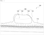
- FIGS. 1 and 2 are exemplary cross-sectional views of a tire manufactured by a method for manufacturing a tire having a sensor container according to an embodiment of the present invention.
- a tire 100 manufactured by a method for manufacturing a tire having a sensor container according to the present invention may include a tire 110, a container unit 120, and a sensor 130.
- the tire 110 may have an inner region of the tire having an inner liner to which the container unit 120 can be attached.
- the container unit 120 is cured and coupled to the tire 110, and may have a container side wall 121, a sensor mounting region 122, a container cover 123, and a sensor insertion hole 124.
- the container side wall 121 may be provided such that a lower portion thereof is integrated with the tire 110 during curing.
- the container side wall 121 has a ringshaped bottom surface that is cured and coupled to the tire 110, and may be formed to have a side wall formed to extend upward from the inner end of the bottom surface to be substantially perpendicular to the tire 110.
- the container side wall 121 may be provided in a circular shape in which the inner ring is filled.
- the bottom surface may be integrated and fixed with the tire 110.
- the sensor mounting region 122 is formed inside the container side wall 121 and may be formed of an empty space having a shape corresponding to the outer shape of the sensor 130.
- the container cover 123 is provided to extend from the upper end of the container side wall 121, and may be formed to cover a portion of the upper portion of the container side wall 121.
- the sensor insertion hole 124 is formed in the central portion of the container cover 123, and may be provided to form a passage through which the sensor 130 can be inserted.
- the diameter of the sensor insertion hole 124 is provided to form a passage through which the sensor 130 can be inserted into the sensor mounting region 122, and the container cover 123 may be formed to fix the sensor 130 inserted into the sensor mounting region 122 not to be detached while driving.
- the senor 130 may be provided to be inserted into the container unit 120 through the sensor insertion hole 124. Further, as long as the container cover 123 is not removed by forcibly spreading both sides, the sensor 130 may be fixed while being inserted into the container unit 120 even during high-speed driving.
- the sensor 130 may be provided to be inserted into the container unit 120 to measure information such as tire pressure, wear level, and acceleration.
- the container unit 120 thus provided is integrally coupled to the tire 110 without an adhesive, and the sensor 130 may also be mounted inside the container unit 120 without an adhesive.
- the sensor 130 is provided to have the same outer shape as a dummy 10, and the shapes of the sensor 130 and inner space of the container unit 120 are provided to be the same. Accordingly, when the sensor 130 is inserted into the container unit 120, the sensor 130 is provided to be in close contact with the inner surface of the container unit 120. Accordingly, the sensor 130 can be stably fixed when inserted into the inner surface of the container unit 120 without an adhesive.
- the senor 130 when the sensor 130 is inserted into the container unit 120, if necessary, the sensor 130 may be inserted and fixed after applying an adhesive such as a bond to the bottom surface.
- the container unit 120 may be provided with a protrusion formed on the inside, and an insertion groove corresponding to a portion in which the protrusion is formed may be formed on the outer surface of the sensor 130. Accordingly, when the sensor 130 is inserted into the container unit 120, the protrusion is inserted into the insertion groove, so that the fixing effect is further improved.
- the insertion groove may be formed inside the container unit 120, and the protrusion may be formed in the sensor 130.
- FIG. 3 is a flowchart of a method for manufacturing a tire having a sensor container according to an embodiment of the present invention.
- the step (S10) of curing the container unit may be performed first.
- the container unit 120 may be prepared to contain 0.1 to 99.5 % by weight of a filler material, 0.1 to 99.5 % by weight of oil, and 0.001 to 30% by weight of sulfur.
- the filler material is made of a rubber-based material formed of a polymer mixture containing natural rubber and synthetic rubber, and it may be made of any one or more of carbon, silica, and organic fillers.
- the oil may be a vegetable oil or a petroleum oil.
- the container unit 120 may be preferably provided to be cured at 180 °C for 120 seconds, but the temperature and curing time are not limited thereto. That is, in the step (S10) of curing the container unit, the container unit 120 may be provided to be cured at a temperature of 170 °C to 190 °C for 110 seconds to 130 seconds.
- the step (S20) of forming a dummy by filling an inside of the cured container unit with a dummy material in which urethane and a curing agent are mixed may be performed.
- the dummy material may be formed by mixing the urethane having a hardness of 1 to 100 and a curing agent in a ratio of 2:8 to 8:2.
- the dummy material may be poured into the sensor mounting region 122 of the container unit 120 to fill the inside of the sensor mounting region 122.
- the dummy material filled in the sensor mounting region 122 may be provided to be cured for 3 minutes.
- the step (S30) of attaching the container unit including the dummy formed by curing to a tire may be performed.
- FIG. 4 is an exemplary view showing a container unit before curing according to an embodiment of the present invention.
- the container unit 120 may be provided to be attached to any point inside the tire 110 having an inner liner.
- the tire 110 is a tire in a state in which only molding is performed without curing.
- the step (S40) of curing the tire to which the container unit is attached may be performed.
- curing may be performed such that the container unit 120 has the hardness of 10 to 100 and the 100% modulus of 50 kgf/cm 2 or less.
- FIG. 5 is an exemplary view showing a container unit after curing according to an embodiment of the present invention.
- the bottom surface of the container side wall 121 may be integrated and fixed with the tire 110.
- the step (S50) of removing the dummy included in the container unit attached to the cured tire may be performed.
- the dummy 10 included in the container unit 120 may be removed by slightly spreading the container cover 123.
- the step (S60) of mounting a sensor at a position where the dummy is removed may be performed.
- FIG. 6 is an exemplary view of a tire manufactured by a method for manufacturing a tire having a sensor container equipped with the sensor according to an embodiment of the present invention.
- the sensor 130 may be inserted into the container unit 120 without applying an adhesive.
- the sensor 130 is inserted into the sensor mounting region 122 through the sensor insertion hole 124 without an adhesive.
- FIG. 7 is an exemplary view showing a dummy according to an embodiment of the present invention.
- the removed dummy 10 may be recycled thereafter.
- the step (S10) of curing the container unit and the step (S20) of forming a dummy by filling an inside of the cured container unit with a dummy material in which urethane and a curing agent are mixed for forming the dummy 10 may be omitted, and the dummy may be recycled in the step (S30) of attaching the container unit having the dummy formed by curing to the tire and the step (S40) of curing the tire to which the container unit is attached.
- the dummy thus formed may be used for more than 200 cycles.
- the present invention thus prepared has an effect that the sensor 130 can be stably mounted on the tire without an adhesive by integrating the container unit 120 with the inner liner or inner side of the tire.
- the senor 130 can be mounted on the tire 110 without an adhesive, there is no problem in that the adhesive is melted due to heat and voids occur during high-speed driving.
- the dummy is used when the container unit 120 is cured to the tire 110, it is possible to prevent the container unit 120 from being deformed and damaged due to a locally applied pressure, etc.
- the dummy used in the container unit 120 maintained the profile shape in the container rubber without damage even at high temperature and high pressure, and the dummy did not show any deformation of the profile or change in hardness even when used for 200 cycles (times).
Landscapes
- Engineering & Computer Science (AREA)
- Mechanical Engineering (AREA)
- Tires In General (AREA)
Abstract
Description
- The present application claims priority to
Korean Patent Application No. 10-2021-0099124, filed July 28, 2021 - The present invention relates to a method for manufacturing a tire having a sensor container and a tire manufactured by the manufacturing method, and more particularly, to a method for manufacturing a tire having a sensor container for preventing the sensor container from falling off during high-speed driving, and a tire manufactured by the manufacturing method.
- Recently, various methods for attaching sensors to the inside of a tire have been devised in order to receive tire status information directly related to the safety of vehicle occupants in real time.
- Products sold in the actual market are released in a way that adhesives are applied to an inner liner rubber inside a cured finished tire and then a cured container having a sensor is attached.
- However, this method causes variations in the ambient environment such as temperature, pressure, and climatic conditions at the time of application of the adhesive, the amount of application and the magnitude of the force applied for adhesion.
- Accordingly, as the heat generated from a tread is transmitted to the inside of the tire during high-speed driving, voids are occurred in the adhesive between the inner liner portion and the sensor container. As the voids occurred in this way gradually expanded, the movement of the sensor increased, making accurate sensing difficult. Further, in severe cases, there was a problem in that the adhesive was peeled off and the sensor inside the tire was damaged, damaging the tire and endangering the safety of the occupants.
- In addition, since the use of adhesives is related to environmental pollution, it does not follow the policies of each tire manufacturer that are currently aiming for eco-friendly products.
- In addition to this, for example, a method including curing a patch on the inner liner of a tire or forming a groove in the inner liner to attach a patch and curing, and then, removing the patch to insert a sensor has been proposed. However, since these technologies are often not practically applicable due to the complicated manufacturing process, in most cases, the container having sensors is attached to the inner liner using an adhesive.
- Therefore, there is a need to develop a technology capable of permanently fixing a sensor container to a tire without using an adhesive while a manufacturing process is simple.
- (Patent Document 1)
Korean Registered Patent No. 1418214 - An object of the present invention to solve the above problems is to provide a method of manufacturing a tire having a sensor container for preventing the sensor container from falling off during high-speed driving, and a tire manufactured by the manufacturing method.
- The technical objects to be achieved by the present invention are not limited to the technical objects mentioned above, and other technical objects not mentioned can be clearly understood by those of ordinary skill in the art to which the present invention belongs from the description below.
- The configuration of the present invention for achieving the above object provides a method for manufacturing a tire having a sensor container, including a) curing a container unit; b) forming a dummy by filling an inside of the cured container unit with a dummy material in which urethane and a curing agent are mixed; c) attaching the container unit including the dummy formed by curing to a tire; d) curing the tire to which the container unit is attached; e) removing the dummy included in the container unit attached to the cured tire; and f) mounting a sensor at a position where the dummy is removed.
- In an embodiment of the present invention, in the step a), the container unit may be prepared to contain 0.1 to 99.5 % by weight of a filler material, 0.1 to 99.5 % by weight of oil, and 0.001 to 30 % by weight of sulfur.
- In an embodiment of the present invention, the filler material may be made of a rubber-based material formed of a polymer mixture containing natural rubber and synthetic rubber, and may be made of any one or more of carbon, silica, and organic filler.
- In an embodiment of the present invention, the oil may be a vegetable oil or a petroleum oil.
- In an embodiment of the present invention, in the step a), the container unit may be provided to be cured at a temperature of 170 °C to 190 °C for 110 seconds to 130 seconds.
- In an embodiment of the present invention, in the step b), the dummy material may be formed by mixing the urethane having a hardness of 1 to 100 and the curing agent in a ratio of 2:8 to 8:2.
- In an embodiment of the present invention, in the step c), the container unit may be provided to be attached to any point inside the tire having an inner liner.
- In an embodiment of the present invention, in the step d), the curing may be performed such that the container unit has a hardness of 10 to 100 and 100% modulus of 50 kgf/cm2 or less.
- In an embodiment of the present invention, in the step f), the sensor may be provided to be inserted into the container unit without applying an adhesive.
- In an embodiment of the present invention, after the step f), the removed dummy may be provided to be recycled in the step c) and the step d) by omitting the step a) and the step b).
- The configuration of the present invention for achieving the above object provides a tire manufactured by the method of manufacturing a tire having a sensor container, including the container unit cured and coupled to the tire; and the sensor inserted into the container unit.
- In an embodiment of the present invention, the container unit may include a container side wall provided such that a lower portion thereof is integrated with the tire during the curing; a sensor mounting region formed inside the container side wall and formed of an empty space having a shape corresponding to an outer shape of the sensor; a container cover formed to cover an upper portion of the container side wall; and a sensor insertion hole formed in a central portion of the container cover.
- In an embodiment of the present invention, a diameter of the sensor insertion hole may be provided to form a passage through which the sensor is inserted into the sensor mounting region and the container cover may be formed to fix the sensor inserted into the sensor mounting region not to be detached while driving.
- The effect of the present invention according to the above configuration is that the sensor can be mounted on the tire without an adhesive by integrating the container unit with the inner liner of the tire or inner side of the tire.
- Since the sensor can be mounted on the tire without an adhesive, when driving at high speed, there is no problem that the adhesive melts due to heat and voids occur.
- In addition, since the dummy is used when curing the container unit to the tire, it is possible to prevent the container unit from being deformed and damaged by the pressure applied locally.
- In addition, as the pressure of a bladder locally acts non-uniformly at the position where the container unit is formed, there is no problem affecting the tire quality.
- It should be understood that the effects of the present invention are not limited to the above-described effects, and include all effects that can be inferred from the configuration of the invention described in the detailed description or claims of the present invention.
-
-
FIGS. 1 and2 are exemplary cross-sectional views of a tire manufactured by a method for manufacturing a tire having a sensor container according to an embodiment of the present invention. -
FIG. 3 is a flowchart of a method for manufacturing a tire including a sensor container according to an embodiment of the present invention. -
FIG. 4 is an exemplary view showing a container unit before curing according to an embodiment of the present invention. -
FIG. 5 is an exemplary view showing a container unit after curing according to an embodiment of the present invention. -
FIG. 6 is an exemplary view of a tire manufactured by a method for manufacturing a tire having a sensor container equipped with a sensor according to an embodiment of the present invention. -
FIG. 7 is an exemplary view showing a dummy according to an embodiment of the present invention. - Hereinafter, the present invention will be described with reference to the accompanying drawings. However, the present invention may be embodied in several different forms, and thus is not limited to the embodiments described herein. Further, in order to clearly explain the present invention in the drawings, parts irrelevant to the description are omitted, and similar reference numerals are attached to similar parts throughout the specification.
- Throughout the specification, when it is said that a part is "connected (accessed, contacted, coupled)" with another part, this includes not only the case of "directly connected" but also the case of "indirectly connected" with another member interposed therebetween. In addition, when a part "includes" a certain component, this means that other components may be further included, rather than excluding other components, unless otherwise stated.
- The terminology used herein is used only to describe specific embodiments, and is not intended to limit the present invention. The singular expression includes the plural expression unless the context clearly dictates otherwise. In the present specification, terms such as "comprise" or "have" are intended to designate that a feature, number, step, operation, component, part, or combination thereof described in the specification exists, and should be understood that it does not preclude the possibility of addition or existence of one or more other features, numbers, steps, operations, components, parts, or combinations thereof in advance.
- Hereinafter, embodiments of the present invention will be described in detail with reference to the accompanying drawings.
-
FIGS. 1 and2 are exemplary cross-sectional views of a tire manufactured by a method for manufacturing a tire having a sensor container according to an embodiment of the present invention. - Referring to
FIGS. 1 and2 , atire 100 manufactured by a method for manufacturing a tire having a sensor container according to the present invention may include atire 110, acontainer unit 120, and asensor 130. - The
tire 110 may have an inner region of the tire having an inner liner to which thecontainer unit 120 can be attached. - The
container unit 120 is cured and coupled to thetire 110, and may have acontainer side wall 121, asensor mounting region 122, acontainer cover 123, and asensor insertion hole 124. - The
container side wall 121 may be provided such that a lower portion thereof is integrated with thetire 110 during curing. Specifically, thecontainer side wall 121 has a ringshaped bottom surface that is cured and coupled to thetire 110, and may be formed to have a side wall formed to extend upward from the inner end of the bottom surface to be substantially perpendicular to thetire 110. In this case, thecontainer side wall 121 may be provided in a circular shape in which the inner ring is filled. - When the
container side wall 121 provided in this way is cured while attached to thetire 110, the bottom surface may be integrated and fixed with thetire 110. - The
sensor mounting region 122 is formed inside thecontainer side wall 121 and may be formed of an empty space having a shape corresponding to the outer shape of thesensor 130. - The
container cover 123 is provided to extend from the upper end of thecontainer side wall 121, and may be formed to cover a portion of the upper portion of thecontainer side wall 121. - The
sensor insertion hole 124 is formed in the central portion of thecontainer cover 123, and may be provided to form a passage through which thesensor 130 can be inserted. - Here, the diameter of the
sensor insertion hole 124 is provided to form a passage through which thesensor 130 can be inserted into thesensor mounting region 122, and thecontainer cover 123 may be formed to fix thesensor 130 inserted into thesensor mounting region 122 not to be detached while driving. - That is, the
sensor 130 may be provided to be inserted into thecontainer unit 120 through thesensor insertion hole 124. Further, as long as thecontainer cover 123 is not removed by forcibly spreading both sides, thesensor 130 may be fixed while being inserted into thecontainer unit 120 even during high-speed driving. - The
sensor 130 may be provided to be inserted into thecontainer unit 120 to measure information such as tire pressure, wear level, and acceleration. - The
container unit 120 thus provided is integrally coupled to thetire 110 without an adhesive, and thesensor 130 may also be mounted inside thecontainer unit 120 without an adhesive. - The
sensor 130 is provided to have the same outer shape as adummy 10, and the shapes of thesensor 130 and inner space of thecontainer unit 120 are provided to be the same. Accordingly, when thesensor 130 is inserted into thecontainer unit 120, thesensor 130 is provided to be in close contact with the inner surface of thecontainer unit 120. Accordingly, thesensor 130 can be stably fixed when inserted into the inner surface of thecontainer unit 120 without an adhesive. - However, when the
sensor 130 is inserted into thecontainer unit 120, if necessary, thesensor 130 may be inserted and fixed after applying an adhesive such as a bond to the bottom surface. - In addition, the
container unit 120 may be provided with a protrusion formed on the inside, and an insertion groove corresponding to a portion in which the protrusion is formed may be formed on the outer surface of thesensor 130. Accordingly, when thesensor 130 is inserted into thecontainer unit 120, the protrusion is inserted into the insertion groove, so that the fixing effect is further improved. Here, the insertion groove may be formed inside thecontainer unit 120, and the protrusion may be formed in thesensor 130. - Hereinafter, a method for manufacturing a tire having a sensor container will be described.
-
FIG. 3 is a flowchart of a method for manufacturing a tire having a sensor container according to an embodiment of the present invention. - Referring to
FIG. 3 , in a method for manufacturing a tire having a sensor container, the step (S10) of curing the container unit may be performed first. - In the step (S10) of curing the container unit, the
container unit 120 may be prepared to contain 0.1 to 99.5 % by weight of a filler material, 0.1 to 99.5 % by weight of oil, and 0.001 to 30% by weight of sulfur. - Here, the filler material is made of a rubber-based material formed of a polymer mixture containing natural rubber and synthetic rubber, and it may be made of any one or more of carbon, silica, and organic fillers.
- Further, the oil may be a vegetable oil or a petroleum oil.
- In the step (S10) of curing the container unit (S10), the
container unit 120 may be preferably provided to be cured at 180 °C for 120 seconds, but the temperature and curing time are not limited thereto. That is, in the step (S10) of curing the container unit, thecontainer unit 120 may be provided to be cured at a temperature of 170 °C to 190 °C for 110 seconds to 130 seconds. - After the step (S10) of curing the container unit, the step (S20) of forming a dummy by filling an inside of the cured container unit with a dummy material in which urethane and a curing agent are mixed may be performed.
- In the step (S20) of forming a dummy by filling an inside of the cured container unit with a dummy material in which urethane and a curing agent are mixed, first, the dummy material may be formed by mixing the urethane having a hardness of 1 to 100 and a curing agent in a ratio of 2:8 to 8:2. In addition, the dummy material may be poured into the
sensor mounting region 122 of thecontainer unit 120 to fill the inside of thesensor mounting region 122. The dummy material filled in thesensor mounting region 122 may be provided to be cured for 3 minutes. - After the step (S20) of forming a dummy by filling an inside of the cured container unit with a dummy material in which urethane and a curing agent are mixed, the step (S30) of attaching the container unit including the dummy formed by curing to a tire may be performed.
-
FIG. 4 is an exemplary view showing a container unit before curing according to an embodiment of the present invention. - Further referring to
FIG. 4 , in the step (S30) of attaching the container unit including the dummy formed by curing to a tire, thecontainer unit 120 may be provided to be attached to any point inside thetire 110 having an inner liner. - Here, the
tire 110 is a tire in a state in which only molding is performed without curing. - After the step (S30) of attaching the container unit including the dummy formed by curing to a tire, the step (S40) of curing the tire to which the container unit is attached may be performed.
- In the step (S40) of curing the tire to which the container unit is attached, curing may be performed such that the
container unit 120 has the hardness of 10 to 100 and the 100% modulus of 50 kgf/cm2 or less. -
FIG. 5 is an exemplary view showing a container unit after curing according to an embodiment of the present invention. - As shown in
FIG. 5 , when the curing is performed in the step (S40) of curing the tire to which the container unit is attached, the bottom surface of thecontainer side wall 121 may be integrated and fixed with thetire 110. - After the step (S40) of curing the tire to which the container unit is attached, the step (S50) of removing the dummy included in the container unit attached to the cured tire may be performed.
- In the step (S50) of removing the dummy included in the container unit attached to the cured tire, the
dummy 10 included in thecontainer unit 120 may be removed by slightly spreading thecontainer cover 123. - After the step (S50) of removing the dummy included in the container unit attached to the cured tire, the step (S60) of mounting a sensor at a position where the dummy is removed may be performed.
-
FIG. 6 is an exemplary view of a tire manufactured by a method for manufacturing a tire having a sensor container equipped with the sensor according to an embodiment of the present invention. - Referring to
FIG. 6 , in the step (S60) of mounting the sensor at a position where the dummy is removed, thesensor 130 may be inserted into thecontainer unit 120 without applying an adhesive. - Specifically, in the step (S60) of mounting the sensor at a position where the dummy is removed, the
sensor 130 is inserted into thesensor mounting region 122 through thesensor insertion hole 124 without an adhesive. -
FIG. 7 is an exemplary view showing a dummy according to an embodiment of the present invention. - As shown in
FIG. 7 , after in the step (S60) of mounting the sensor at a position where the dummy is removed, the removeddummy 10 may be recycled thereafter. - Specifically, the step (S10) of curing the container unit and the step (S20) of forming a dummy by filling an inside of the cured container unit with a dummy material in which urethane and a curing agent are mixed for forming the
dummy 10 may be omitted, and the dummy may be recycled in the step (S30) of attaching the container unit having the dummy formed by curing to the tire and the step (S40) of curing the tire to which the container unit is attached. - The dummy thus formed may be used for more than 200 cycles.
- After attaching the
container unit 120 having thesensor 130 to the inside of the 280/680R18 F200 tire 110, a high-speed endurance driving test was performed at a camber of 4 degrees, a load of 350 kg, and 200 km/h. As a result, there was no problem of thesensor 130 detaching from thecontainer unit 120 or thetire 110, and no sensor detachment problem or sensor recognition problem occurred even during actual driving at a speed of 290 km/h for 2 hours. - The present invention thus prepared has an effect that the
sensor 130 can be stably mounted on the tire without an adhesive by integrating thecontainer unit 120 with the inner liner or inner side of the tire. - In addition, according to the present invention, since the
sensor 130 can be mounted on thetire 110 without an adhesive, there is no problem in that the adhesive is melted due to heat and voids occur during high-speed driving. - In addition, according to the present invention, since the dummy is used when the
container unit 120 is cured to thetire 110, it is possible to prevent thecontainer unit 120 from being deformed and damaged due to a locally applied pressure, etc. - As a result of checking the cross-section of the actual tire, there was no phenomenon in which the portion where a bladder did not touch between the bottom surface to which the
sensor container unit 120 was attached and the inner portion of thetire 110 was not cured. It was confirmed that there was no difference between the physical properties of the tread rubber at the position vertically lowered to the outside thetire 110 from the portion where thecontainer unit 120 is attached and the physical properties of the tread rubber positioned next to it and not affected by thecontainer unit 120. In addition, when the bladder pushed the inside of thetire 110, it was expected that there would be a deformation in the arrangement of the nylon and steel cords in the region pressed by the dummy, but as shown inFIG. 1 , it was confirmed that no deformation occurred when compared with other regions. - In addition, as a result of checking whether the bladder was damaged after curing, no deformation of the bladder was found after 200 cycles, and the change in the expansion pressure of the bladder during curing was not different from that when the
container unit 120 was not attached. - The dummy used in the
container unit 120 maintained the profile shape in the container rubber without damage even at high temperature and high pressure, and the dummy did not show any deformation of the profile or change in hardness even when used for 200 cycles (times). - The above description of the present invention is for illustrative purposes, and those of ordinary skill in the art to which the present invention pertains will be able to understand that the embodiment can be easily transform into other specific forms without changing the technical spirit or essential features of the present invention. Therefore, it should be understood that the embodiments described above are illustrative in all respects and not restrictive. For example, each component described as a single type may be implemented in a dispersed form, and likewise components described as dispersed may be implemented in a combined form.
- The scope of the present invention is indicated by the following claims, and all changes or modifications derived from the meaning and scope of the claims and their equivalents should be interpreted as being included in the scope of the present invention.
-
- 100:
- tire manufactured by a method for manufacturing a tire having a sensor container
- 110:
- tire
- 120:
- container unit
- 121:
- container side wall
- 122:
- sensor mounting region
- 123:
- container cover
- 124:
- sensor insertion hole
- 130:
- sensor
Claims (13)
- A method for manufacturing a tire comprising a sensor container, the method comprising the steps of:a) curing a container unit;b) forming a dummy by filling an inside of the cured container unit with a dummy material in which urethane and a curing agent are mixed;c) attaching the container unit including the dummy formed by curing, to a tire;d) curing the tire to which the container unit is attached;e) removing the dummy included in the container unit attached to the cured tire; andf) mounting a sensor at a position where the dummy is removed.
- The method according to claim 1, wherein in the step a), the container unit is prepared to contain 0.1 to 99.5 % by weight of a filler material, 0.1 to 99.5 % by weight of oil, and 0.001 to 30 % by weight of sulfur.
- The method according to claim 2, wherein the filler material is made of a rubber-based material formed of a polymer mixture containing natural rubber and synthetic rubber, and is made of any one or more of carbon, silica, and organic filler.
- The method according to claim 2, wherein the oil is a vegetable oil or a petroleum oil.
- The method according to claim 1, wherein in the step a), the container unit is provided to be cured at a temperature of 170 °C to 190 °C for 110 seconds to 130 seconds.
- The method according to claim 1, wherein in the step b), the dummy material is formed by mixing the urethane having a hardness of 1 to 100 and the curing agent in a ratio of 2:8 to 8:2.
- The method according to claim 1, wherein in the step c), the container unit is provided to be attached to any point inside the tire having an inner liner.
- The method according to claim 1, wherein in the step d), the curing is performed such that the container unit has a hardness of 10 to 100 and 100% modulus of 50 kgf/cm2 or less.
- The method according to claim 1, wherein in the step f), the sensor is provided to be inserted into the container unit without applying an adhesive.
- The method according to claim 1, wherein after the step f), the removed dummy is provided to be recycled in the step c) and the step d) by omitting the step a) and the step b).
- A tire manufactured by the method of manufacturing a tire comprising a sensor container according to claim 1, comprising:the container unit cured and coupled to the tire; andthe sensor inserted into the container unit.
- The tire according to claim 11, wherein the container unit includes:a container side wall provided such that a lower portion of the container side wall is integrated with the tire during the curing;a sensor mounting region formed inside the container side wall and formed of an empty space having a shape corresponding to an outer shape of the sensor;a container cover formed to cover an upper portion of the container side wall; anda sensor insertion hole formed in a central portion of the container cover.
- The tire according to claim 12, wherein a diameter of the sensor insertion hole is provided to form a passage through which the sensor is inserted into the sensor mounting region and the container cover is formed to fix the sensor inserted into the sensor mounting region not to be detached while driving.
Applications Claiming Priority (1)
| Application Number | Priority Date | Filing Date | Title |
|---|---|---|---|
| KR1020210099124A KR102521633B1 (en) | 2021-07-28 | 2021-07-28 | Manufacturing method of tire having sensor container and tire manufactured by same |
Publications (2)
| Publication Number | Publication Date |
|---|---|
| EP4124447A1 true EP4124447A1 (en) | 2023-02-01 |
| EP4124447B1 EP4124447B1 (en) | 2025-09-03 |
Family
ID=82781232
Family Applications (1)
| Application Number | Title | Priority Date | Filing Date |
|---|---|---|---|
| EP22187584.2A Active EP4124447B1 (en) | 2021-07-28 | 2022-07-28 | Manufacturing method of tire having sensor container |
Country Status (4)
| Country | Link |
|---|---|
| US (1) | US20230036044A1 (en) |
| EP (1) | EP4124447B1 (en) |
| KR (1) | KR102521633B1 (en) |
| CN (1) | CN115674747A (en) |
Families Citing this family (1)
| Publication number | Priority date | Publication date | Assignee | Title |
|---|---|---|---|---|
| EP4620661A1 (en) * | 2024-03-19 | 2025-09-24 | Continental Reifen Deutschland GmbH | Device for automatically receiving and inserting a retaining strip of a transponder unit into a raw tire and corresponding method |
Citations (7)
| Publication number | Priority date | Publication date | Assignee | Title |
|---|---|---|---|---|
| DE202005005144U1 (en) * | 2005-03-31 | 2005-06-23 | Stahlgruber Otto Gruber Gmbh & Co Kg | Holder for fixing an electronic component to a rubber article |
| DE102007014211A1 (en) * | 2007-03-24 | 2008-09-25 | Continental Aktiengesellschaft | Container for releasably securing an electronic module to the tire inner side of a motor vehicle tire |
| DE102007030231A1 (en) * | 2007-06-29 | 2009-01-08 | Continental Aktiengesellschaft | Tire module for vehicle, has electronic module held in box over circular form closure, and air cushion and lower plate, which are arranged between lower side of electronic module and inner side of tire for absorbing mechanical stresses |
| DE102008004065A1 (en) * | 2008-01-12 | 2009-07-16 | Continental Aktiengesellschaft | Tire module for vehicle tires |
| WO2010043264A1 (en) * | 2008-10-16 | 2010-04-22 | Pirelli Tyre S.P.A. | A tyre comprising an electronic unit |
| KR101418214B1 (en) | 2013-05-29 | 2014-07-09 | 금호타이어 주식회사 | Automatic Adhesion Device of Sensor for Intelligent Tire |
| EP3549754A1 (en) * | 2018-04-05 | 2019-10-09 | Continental Reifen Deutschland GmbH | Method for producing a tyre for a vehicle |
Family Cites Families (12)
| Publication number | Priority date | Publication date | Assignee | Title |
|---|---|---|---|---|
| US6030478A (en) * | 1998-02-10 | 2000-02-29 | Bridgestone/Firestone, Inc. | Method and apparatus for removably inserting an electric tire tag into a tire |
| US6355196B1 (en) * | 1998-03-16 | 2002-03-12 | Vantico Inc. | Process for producing direct tooling mold and method for using the same |
| EP1497092A1 (en) * | 2002-04-15 | 2005-01-19 | Dow Global Technologies Inc. | Improved vehicular structural members and method of making the members |
| WO2007049093A1 (en) * | 2005-10-28 | 2007-05-03 | Pirelli Tyre S.P.A. | A tyre comprising an electronic unit and a method of installing said electronic unit into said tyre |
| US20140261944A1 (en) * | 2013-03-15 | 2014-09-18 | The Goodyear Tire & Rubber Company | Encasing for releasably containing a device and tire containing such encasing or encased device |
| KR101760872B1 (en) * | 2015-08-24 | 2017-07-24 | 한국타이어 주식회사 | Pneumatic tire comprising sensor patch and method for manufacturing the same |
| KR101925774B1 (en) * | 2017-11-30 | 2018-12-10 | 한국타이어 주식회사 | Method of manufacturing tire integral type container structure |
| EP3492289B1 (en) * | 2017-11-30 | 2021-01-06 | Hankook Tire Co., Ltd. | Container structure for attaching sensors to tires and method of manufacturing tire container structure |
| DE102018215314A1 (en) * | 2018-09-10 | 2020-03-12 | Continental Reifen Deutschland Gmbh | Method for inserting sensors into a tread of a vehicle tire |
| CN113056378B (en) * | 2018-11-19 | 2023-09-05 | 米其林集团总公司 | Integrated tire monitoring sensor container |
| JP7192433B2 (en) * | 2018-11-21 | 2022-12-20 | 横浜ゴム株式会社 | pneumatic tire |
| DE102019219204A1 (en) * | 2019-12-10 | 2021-06-10 | Continental Reifen Deutschland Gmbh | Method for attaching a receiving body to a tire |
-
2021
- 2021-07-28 KR KR1020210099124A patent/KR102521633B1/en active Active
-
2022
- 2022-07-28 US US17/876,029 patent/US20230036044A1/en not_active Abandoned
- 2022-07-28 EP EP22187584.2A patent/EP4124447B1/en active Active
- 2022-07-28 CN CN202210899669.3A patent/CN115674747A/en active Pending
Patent Citations (7)
| Publication number | Priority date | Publication date | Assignee | Title |
|---|---|---|---|---|
| DE202005005144U1 (en) * | 2005-03-31 | 2005-06-23 | Stahlgruber Otto Gruber Gmbh & Co Kg | Holder for fixing an electronic component to a rubber article |
| DE102007014211A1 (en) * | 2007-03-24 | 2008-09-25 | Continental Aktiengesellschaft | Container for releasably securing an electronic module to the tire inner side of a motor vehicle tire |
| DE102007030231A1 (en) * | 2007-06-29 | 2009-01-08 | Continental Aktiengesellschaft | Tire module for vehicle, has electronic module held in box over circular form closure, and air cushion and lower plate, which are arranged between lower side of electronic module and inner side of tire for absorbing mechanical stresses |
| DE102008004065A1 (en) * | 2008-01-12 | 2009-07-16 | Continental Aktiengesellschaft | Tire module for vehicle tires |
| WO2010043264A1 (en) * | 2008-10-16 | 2010-04-22 | Pirelli Tyre S.P.A. | A tyre comprising an electronic unit |
| KR101418214B1 (en) | 2013-05-29 | 2014-07-09 | 금호타이어 주식회사 | Automatic Adhesion Device of Sensor for Intelligent Tire |
| EP3549754A1 (en) * | 2018-04-05 | 2019-10-09 | Continental Reifen Deutschland GmbH | Method for producing a tyre for a vehicle |
Also Published As
| Publication number | Publication date |
|---|---|
| KR102521633B1 (en) | 2023-04-14 |
| KR20230017952A (en) | 2023-02-07 |
| CN115674747A (en) | 2023-02-03 |
| US20230036044A1 (en) | 2023-02-02 |
| EP4124447B1 (en) | 2025-09-03 |
Similar Documents
| Publication | Publication Date | Title |
|---|---|---|
| EP4124447A1 (en) | Manufacturing method of tire having sensor container and tire manufactured by the same | |
| US12128716B2 (en) | Tyre monitoring device comprising an electronic unit and tyre comprising said device | |
| US10800585B2 (en) | Manufacturing method for metal cap | |
| EP3756909B1 (en) | Tire integrated with electronic device and manufacturing method thereof | |
| JP2020026268A (en) | Tire sensor fixed by screw method and tire using the same | |
| EP1759893A1 (en) | Balanced tire and method for manufacturing thereof | |
| US6128952A (en) | Tire balancing using glass beads | |
| US20200164696A1 (en) | Method and apparatus for utilizing preprinted labels and appliqués on a tire | |
| EP3865291A1 (en) | Manufacturing method of tire integrated electronic device, integrated electronic device obtained thereby and tire | |
| EP3364065A1 (en) | Torque rod, and method for manufacturing torque rod | |
| US6944948B2 (en) | Device for sealing a lubricant reservoir and method for lubricating the internal cavity of a tire | |
| KR102730034B1 (en) | A manufacturing method of tire including sensor container and tire including sensor container manufactured thereby | |
| WO2004050392A1 (en) | Pneumatic safety tire | |
| US12589619B2 (en) | System for measuring the internal temperature of a running tire | |
| JP2005240039A (en) | Method of using adhesive to assemble member and wheel, member and wheel assembly, member and wheel | |
| KR20210091400A (en) | A pneumatic tire | |
| KR102463536B1 (en) | A pneumatic tire type stud, pneumatic tire comprising the same and manufacturing method thereof | |
| US20240230420A9 (en) | Tire instrumentation method for measuring the internal temperature during rolling | |
| KR200489733Y1 (en) | Tire having combination for sensor | |
| KR20250009926A (en) | Noise reducing pneumatic tires and their manufacturing method | |
| KR102326906B1 (en) | Sealant member for pneumatic tire | |
| KR20230135223A (en) | Pneumatic tire with sound absorbing material and manufacturing method thereof | |
| RU2772599C2 (en) | Tire control device containing electronic unit, and tire containing specified device | |
| CN206484793U (en) | The sulfurizing mould of conical rubber pile | |
| CN121019154A (en) | A low-profile bicycle tire |
Legal Events
| Date | Code | Title | Description |
|---|---|---|---|
| PUAI | Public reference made under article 153(3) epc to a published international application that has entered the european phase |
Free format text: ORIGINAL CODE: 0009012 |
|
| STAA | Information on the status of an ep patent application or granted ep patent |
Free format text: STATUS: REQUEST FOR EXAMINATION WAS MADE |
|
| 17P | Request for examination filed |
Effective date: 20220728 |
|
| AK | Designated contracting states |
Kind code of ref document: A1 Designated state(s): AL AT BE BG CH CY CZ DE DK EE ES FI FR GB GR HR HU IE IS IT LI LT LU LV MC MK MT NL NO PL PT RO RS SE SI SK SM TR |
|
| STAA | Information on the status of an ep patent application or granted ep patent |
Free format text: STATUS: EXAMINATION IS IN PROGRESS |
|
| 17Q | First examination report despatched |
Effective date: 20240612 |
|
| 17Q | First examination report despatched |
Effective date: 20240626 |
|
| GRAP | Despatch of communication of intention to grant a patent |
Free format text: ORIGINAL CODE: EPIDOSNIGR1 |
|
| STAA | Information on the status of an ep patent application or granted ep patent |
Free format text: STATUS: GRANT OF PATENT IS INTENDED |
|
| INTG | Intention to grant announced |
Effective date: 20250422 |
|
| GRAS | Grant fee paid |
Free format text: ORIGINAL CODE: EPIDOSNIGR3 |
|
| GRAA | (expected) grant |
Free format text: ORIGINAL CODE: 0009210 |
|
| STAA | Information on the status of an ep patent application or granted ep patent |
Free format text: STATUS: THE PATENT HAS BEEN GRANTED |
|
| AK | Designated contracting states |
Kind code of ref document: B1 Designated state(s): AL AT BE BG CH CY CZ DE DK EE ES FI FR GB GR HR HU IE IS IT LI LT LU LV MC MK MT NL NO PL PT RO RS SE SI SK SM TR |
|
| REG | Reference to a national code |
Ref country code: CH Ref legal event code: EP |
|
| REG | Reference to a national code |
Ref country code: DE Ref legal event code: R096 Ref document number: 602022020620 Country of ref document: DE |
|
| REG | Reference to a national code |
Ref country code: IE Ref legal event code: FG4D |
|
| REG | Reference to a national code |
Ref country code: NL Ref legal event code: MP Effective date: 20250903 |
|
| PG25 | Lapsed in a contracting state [announced via postgrant information from national office to epo] |
Ref country code: NO Free format text: LAPSE BECAUSE OF FAILURE TO SUBMIT A TRANSLATION OF THE DESCRIPTION OR TO PAY THE FEE WITHIN THE PRESCRIBED TIME-LIMIT Effective date: 20251203 |
|
| REG | Reference to a national code |
Ref country code: LT Ref legal event code: MG9D |
|
| PG25 | Lapsed in a contracting state [announced via postgrant information from national office to epo] |
Ref country code: FI Free format text: LAPSE BECAUSE OF FAILURE TO SUBMIT A TRANSLATION OF THE DESCRIPTION OR TO PAY THE FEE WITHIN THE PRESCRIBED TIME-LIMIT Effective date: 20250903 |
|
| PG25 | Lapsed in a contracting state [announced via postgrant information from national office to epo] |
Ref country code: HR Free format text: LAPSE BECAUSE OF FAILURE TO SUBMIT A TRANSLATION OF THE DESCRIPTION OR TO PAY THE FEE WITHIN THE PRESCRIBED TIME-LIMIT Effective date: 20250903 |
|
| PG25 | Lapsed in a contracting state [announced via postgrant information from national office to epo] |
Ref country code: GR Free format text: LAPSE BECAUSE OF FAILURE TO SUBMIT A TRANSLATION OF THE DESCRIPTION OR TO PAY THE FEE WITHIN THE PRESCRIBED TIME-LIMIT Effective date: 20251204 |
|
| PG25 | Lapsed in a contracting state [announced via postgrant information from national office to epo] |
Ref country code: SE Free format text: LAPSE BECAUSE OF FAILURE TO SUBMIT A TRANSLATION OF THE DESCRIPTION OR TO PAY THE FEE WITHIN THE PRESCRIBED TIME-LIMIT Effective date: 20250903 |
|
| PG25 | Lapsed in a contracting state [announced via postgrant information from national office to epo] |
Ref country code: LV Free format text: LAPSE BECAUSE OF FAILURE TO SUBMIT A TRANSLATION OF THE DESCRIPTION OR TO PAY THE FEE WITHIN THE PRESCRIBED TIME-LIMIT Effective date: 20250903 |
|
| PG25 | Lapsed in a contracting state [announced via postgrant information from national office to epo] |
Ref country code: PL Free format text: LAPSE BECAUSE OF FAILURE TO SUBMIT A TRANSLATION OF THE DESCRIPTION OR TO PAY THE FEE WITHIN THE PRESCRIBED TIME-LIMIT Effective date: 20250903 Ref country code: BG Free format text: LAPSE BECAUSE OF FAILURE TO SUBMIT A TRANSLATION OF THE DESCRIPTION OR TO PAY THE FEE WITHIN THE PRESCRIBED TIME-LIMIT Effective date: 20250903 |
|
| PG25 | Lapsed in a contracting state [announced via postgrant information from national office to epo] |
Ref country code: RS Free format text: LAPSE BECAUSE OF FAILURE TO SUBMIT A TRANSLATION OF THE DESCRIPTION OR TO PAY THE FEE WITHIN THE PRESCRIBED TIME-LIMIT Effective date: 20251203 |
|
| PG25 | Lapsed in a contracting state [announced via postgrant information from national office to epo] |
Ref country code: ES Free format text: LAPSE BECAUSE OF FAILURE TO SUBMIT A TRANSLATION OF THE DESCRIPTION OR TO PAY THE FEE WITHIN THE PRESCRIBED TIME-LIMIT Effective date: 20250903 |
|
| REG | Reference to a national code |
Ref country code: AT Ref legal event code: MK05 Ref document number: 1832550 Country of ref document: AT Kind code of ref document: T Effective date: 20250903 |
|
| PG25 | Lapsed in a contracting state [announced via postgrant information from national office to epo] |
Ref country code: NL Free format text: LAPSE BECAUSE OF FAILURE TO SUBMIT A TRANSLATION OF THE DESCRIPTION OR TO PAY THE FEE WITHIN THE PRESCRIBED TIME-LIMIT Effective date: 20250903 |
|
| PG25 | Lapsed in a contracting state [announced via postgrant information from national office to epo] |
Ref country code: SM Free format text: LAPSE BECAUSE OF FAILURE TO SUBMIT A TRANSLATION OF THE DESCRIPTION OR TO PAY THE FEE WITHIN THE PRESCRIBED TIME-LIMIT Effective date: 20250903 |
|
| PG25 | Lapsed in a contracting state [announced via postgrant information from national office to epo] |
Ref country code: AT Free format text: LAPSE BECAUSE OF FAILURE TO SUBMIT A TRANSLATION OF THE DESCRIPTION OR TO PAY THE FEE WITHIN THE PRESCRIBED TIME-LIMIT Effective date: 20250903 |
|
| PG25 | Lapsed in a contracting state [announced via postgrant information from national office to epo] |
Ref country code: IT Free format text: LAPSE BECAUSE OF FAILURE TO SUBMIT A TRANSLATION OF THE DESCRIPTION OR TO PAY THE FEE WITHIN THE PRESCRIBED TIME-LIMIT Effective date: 20250903 |
|
| PG25 | Lapsed in a contracting state [announced via postgrant information from national office to epo] |
Ref country code: IS Free format text: LAPSE BECAUSE OF FAILURE TO SUBMIT A TRANSLATION OF THE DESCRIPTION OR TO PAY THE FEE WITHIN THE PRESCRIBED TIME-LIMIT Effective date: 20260103 |
|
| PG25 | Lapsed in a contracting state [announced via postgrant information from national office to epo] |
Ref country code: PT Free format text: LAPSE BECAUSE OF FAILURE TO SUBMIT A TRANSLATION OF THE DESCRIPTION OR TO PAY THE FEE WITHIN THE PRESCRIBED TIME-LIMIT Effective date: 20260105 Ref country code: CZ Free format text: LAPSE BECAUSE OF FAILURE TO SUBMIT A TRANSLATION OF THE DESCRIPTION OR TO PAY THE FEE WITHIN THE PRESCRIBED TIME-LIMIT Effective date: 20250903 |
|
| PG25 | Lapsed in a contracting state [announced via postgrant information from national office to epo] |
Ref country code: SK Free format text: LAPSE BECAUSE OF FAILURE TO SUBMIT A TRANSLATION OF THE DESCRIPTION OR TO PAY THE FEE WITHIN THE PRESCRIBED TIME-LIMIT Effective date: 20250903 Ref country code: EE Free format text: LAPSE BECAUSE OF FAILURE TO SUBMIT A TRANSLATION OF THE DESCRIPTION OR TO PAY THE FEE WITHIN THE PRESCRIBED TIME-LIMIT Effective date: 20250903 |