EP3865291A1 - Manufacturing method of tire integrated electronic device, integrated electronic device obtained thereby and tire - Google Patents
Manufacturing method of tire integrated electronic device, integrated electronic device obtained thereby and tire Download PDFInfo
- Publication number
- EP3865291A1 EP3865291A1 EP21157601.2A EP21157601A EP3865291A1 EP 3865291 A1 EP3865291 A1 EP 3865291A1 EP 21157601 A EP21157601 A EP 21157601A EP 3865291 A1 EP3865291 A1 EP 3865291A1
- Authority
- EP
- European Patent Office
- Prior art keywords
- electronic device
- unit
- tire
- manufacturing
- mockup
- Prior art date
- Legal status (The legal status is an assumption and is not a legal conclusion. Google has not performed a legal analysis and makes no representation as to the accuracy of the status listed.)
- Pending
Links
- 238000004519 manufacturing process Methods 0.000 title claims abstract description 26
- 229920001971 elastomer Polymers 0.000 claims abstract description 97
- 239000005060 rubber Substances 0.000 claims abstract description 97
- 238000003780 insertion Methods 0.000 claims abstract description 31
- 230000037431 insertion Effects 0.000 claims abstract description 31
- 238000000748 compression moulding Methods 0.000 claims abstract description 8
- 238000001746 injection moulding Methods 0.000 claims abstract description 8
- 238000004073 vulcanization Methods 0.000 claims description 23
- 238000004132 cross linking Methods 0.000 claims description 5
- 238000000034 method Methods 0.000 description 15
- 230000001133 acceleration Effects 0.000 description 9
- 239000000853 adhesive Substances 0.000 description 8
- 230000001070 adhesive effect Effects 0.000 description 8
- 230000000694 effects Effects 0.000 description 8
- 239000006260 foam Substances 0.000 description 3
- 238000000465 moulding Methods 0.000 description 3
- 244000043261 Hevea brasiliensis Species 0.000 description 2
- 238000011156 evaluation Methods 0.000 description 2
- 239000003292 glue Substances 0.000 description 2
- 238000009434 installation Methods 0.000 description 2
- 238000005259 measurement Methods 0.000 description 2
- 229920003052 natural elastomer Polymers 0.000 description 2
- 229920001194 natural rubber Polymers 0.000 description 2
- 230000035945 sensitivity Effects 0.000 description 2
- 229920003051 synthetic elastomer Polymers 0.000 description 2
- 239000005061 synthetic rubber Substances 0.000 description 2
- 239000004593 Epoxy Substances 0.000 description 1
- 230000005540 biological transmission Effects 0.000 description 1
- 238000009413 insulation Methods 0.000 description 1
- 239000007788 liquid Substances 0.000 description 1
- 239000000203 mixture Substances 0.000 description 1
- 238000012986 modification Methods 0.000 description 1
- 230000004048 modification Effects 0.000 description 1
- 229920000642 polymer Polymers 0.000 description 1
- 238000009958 sewing Methods 0.000 description 1
- 239000013464 silicone adhesive Substances 0.000 description 1
- 239000007787 solid Substances 0.000 description 1
Images


Classifications
-
- B—PERFORMING OPERATIONS; TRANSPORTING
- B29—WORKING OF PLASTICS; WORKING OF SUBSTANCES IN A PLASTIC STATE IN GENERAL
- B29D—PRODUCING PARTICULAR ARTICLES FROM PLASTICS OR FROM SUBSTANCES IN A PLASTIC STATE
- B29D30/00—Producing pneumatic or solid tyres or parts thereof
- B29D30/06—Pneumatic tyres or parts thereof (e.g. produced by casting, moulding, compression moulding, injection moulding, centrifugal casting)
- B29D30/0681—Parts of pneumatic tyres; accessories, auxiliary operations
-
- B—PERFORMING OPERATIONS; TRANSPORTING
- B29—WORKING OF PLASTICS; WORKING OF SUBSTANCES IN A PLASTIC STATE IN GENERAL
- B29C—SHAPING OR JOINING OF PLASTICS; SHAPING OF MATERIAL IN A PLASTIC STATE, NOT OTHERWISE PROVIDED FOR; AFTER-TREATMENT OF THE SHAPED PRODUCTS, e.g. REPAIRING
- B29C45/00—Injection moulding, i.e. forcing the required volume of moulding material through a nozzle into a closed mould; Apparatus therefor
- B29C45/14—Injection moulding, i.e. forcing the required volume of moulding material through a nozzle into a closed mould; Apparatus therefor incorporating preformed parts or layers, e.g. injection moulding around inserts or for coating articles
- B29C45/14336—Coating a portion of the article, e.g. the edge of the article
-
- B—PERFORMING OPERATIONS; TRANSPORTING
- B29—WORKING OF PLASTICS; WORKING OF SUBSTANCES IN A PLASTIC STATE IN GENERAL
- B29D—PRODUCING PARTICULAR ARTICLES FROM PLASTICS OR FROM SUBSTANCES IN A PLASTIC STATE
- B29D30/00—Producing pneumatic or solid tyres or parts thereof
- B29D30/0061—Accessories, details or auxiliary operations not otherwise provided for
-
- B—PERFORMING OPERATIONS; TRANSPORTING
- B29—WORKING OF PLASTICS; WORKING OF SUBSTANCES IN A PLASTIC STATE IN GENERAL
- B29D—PRODUCING PARTICULAR ARTICLES FROM PLASTICS OR FROM SUBSTANCES IN A PLASTIC STATE
- B29D30/00—Producing pneumatic or solid tyres or parts thereof
- B29D30/06—Pneumatic tyres or parts thereof (e.g. produced by casting, moulding, compression moulding, injection moulding, centrifugal casting)
- B29D30/0601—Vulcanising tyres; Vulcanising presses for tyres
- B29D30/0662—Accessories, details or auxiliary operations
-
- B—PERFORMING OPERATIONS; TRANSPORTING
- B29—WORKING OF PLASTICS; WORKING OF SUBSTANCES IN A PLASTIC STATE IN GENERAL
- B29D—PRODUCING PARTICULAR ARTICLES FROM PLASTICS OR FROM SUBSTANCES IN A PLASTIC STATE
- B29D30/00—Producing pneumatic or solid tyres or parts thereof
- B29D30/06—Pneumatic tyres or parts thereof (e.g. produced by casting, moulding, compression moulding, injection moulding, centrifugal casting)
- B29D30/0678—Injection moulding specially adapted for tyres or parts thereof
-
- B—PERFORMING OPERATIONS; TRANSPORTING
- B60—VEHICLES IN GENERAL
- B60C—VEHICLE TYRES; TYRE INFLATION; TYRE CHANGING; CONNECTING VALVES TO INFLATABLE ELASTIC BODIES IN GENERAL; DEVICES OR ARRANGEMENTS RELATED TO TYRES
- B60C23/00—Devices for measuring, signalling, controlling, or distributing tyre pressure or temperature, specially adapted for mounting on vehicles; Arrangement of tyre inflating devices on vehicles, e.g. of pumps or of tanks; Tyre cooling arrangements
- B60C23/02—Signalling devices actuated by tyre pressure
- B60C23/04—Signalling devices actuated by tyre pressure mounted on the wheel or tyre
- B60C23/0491—Constructional details of means for attaching the control device
- B60C23/0493—Constructional details of means for attaching the control device for attachment on the tyre
-
- B—PERFORMING OPERATIONS; TRANSPORTING
- B29—WORKING OF PLASTICS; WORKING OF SUBSTANCES IN A PLASTIC STATE IN GENERAL
- B29D—PRODUCING PARTICULAR ARTICLES FROM PLASTICS OR FROM SUBSTANCES IN A PLASTIC STATE
- B29D30/00—Producing pneumatic or solid tyres or parts thereof
- B29D30/0061—Accessories, details or auxiliary operations not otherwise provided for
- B29D2030/0072—Attaching fasteners to tyres, e.g. patches, in order to connect devices to tyres
-
- B—PERFORMING OPERATIONS; TRANSPORTING
- B29—WORKING OF PLASTICS; WORKING OF SUBSTANCES IN A PLASTIC STATE IN GENERAL
- B29D—PRODUCING PARTICULAR ARTICLES FROM PLASTICS OR FROM SUBSTANCES IN A PLASTIC STATE
- B29D30/00—Producing pneumatic or solid tyres or parts thereof
- B29D30/06—Pneumatic tyres or parts thereof (e.g. produced by casting, moulding, compression moulding, injection moulding, centrifugal casting)
- B29D30/0681—Parts of pneumatic tyres; accessories, auxiliary operations
- B29D2030/0682—Inner liners
-
- B—PERFORMING OPERATIONS; TRANSPORTING
- B29—WORKING OF PLASTICS; WORKING OF SUBSTANCES IN A PLASTIC STATE IN GENERAL
- B29L—INDEXING SCHEME ASSOCIATED WITH SUBCLASS B29C, RELATING TO PARTICULAR ARTICLES
- B29L2031/00—Other particular articles
- B29L2031/34—Electrical apparatus, e.g. sparking plugs or parts thereof
Definitions
- the present invention relates to a manufacturing method of a tire integrated electronic device, and more specifically, a manufacturing method of a tire integrated electronic device by which the electronic device is inhibited from damaging a tire by being detached from a rubber mount.
- Korean Patent Registration No. 0614520 discloses a method of directly attaching a tire attached sensor to a tire by using an epoxy-based adhesive which has viscosity at room temperature and is hardened at a temperature equal to or lower than 100°C.
- hardening of the adhesive takes at least several to 24 hours.
- the sensor is attached in an appropriate manner when a tire is released during a tire manufacturing process or attachment has to be completed in advance in a case of replacement of a tire.
- a sensor is directly exposed to the outside, and thus there is a high possibility that a sensor will be damaged when foreign matter is contained inside a tire.
- United States Patent No. 6788192 discloses a method in which a tire sensor is attached to a side wall and is vulcanized during a molding process. Since the sensor is attached under an inner liner, it is not possible to replace the sensor. In addition, in a case of measuring pressure of a tire, there is a disadvantage that the sensor is covered with the inner liner and thus it is difficult to use a sensor such as a MEMS which detects air pressure in a hole of a pressure sensor.
- United States Patent No. 8561659 discloses a method in which a foam strip is formed at a tire inner surface, that is, a surface of an inner liner, and a sensor is positioned inside the foam strip. Since the foam strip is flexible, acceleration information which is transmitted through a tire is not directly transmitted to the sensor. Hence, it is inconvenient that the acceleration information has to be compared with a value directly measured at a tire surface.
- United States Patent Application No. 2009-0071249 discloses an embodiment in which an acceleration sensor is embedded inside a tire.
- the acceleration sensor since the acceleration sensor is embedded inside the tire, there is no risk of detachment of the sensor due to movement of the tire; however, the sensor is contained in a tire structure as foreign matter and thus durability can be affected.
- United States Patent No. 9016118 discloses a pocket structure into which a tire attached sensor is inserted.
- the pocket structure is formed by steps of forming a patch for forming a pocket on an inner liner through an adhesive attaching method, a molding method, or a vulcanization method and forming a mounting structure on the patch.
- a structure in which a hole is formed at a side of the mounting structure to improve transmission and reception sensitivity of radio waves and enhance liquid flow is employed.
- an interface therebetween is vulnerable to an external force, and thus there is a high possibility that the sensor can be detached during rotation of a tire.
- United States Patent No. 9016339 discloses a method in which a fastener, to which a sensor can be coupled, is disposed and vulcanized to be fixed on a carcass at a tire inner surface, and then the sensor is coupled to the fastener.
- the sensor can be replaced by using the fastener, and adhesion is more increased by using a vulcanization method than using an adhesive.
- a fastener since a fastener has to be inserted before a vulcanization process, there is a disadvantage of adding a further manufacturing process, and there is another disadvantage that pressure can be ununiformly applied during vulcanization due to the fastener.
- United States Patent Application No. 2006-0158340 discloses a method in which a patch is attached to a vulcanized tire and a sensor is inserted into the patch.
- the attachment of a patch is performed by attaching various rubber patches to a cured tire and fixing the patches by sewing or using an adhesive so as not to be detached.
- stress is applied in an unintegrated method, and a problem arises in that there is a high possibility that a patch can be detached when a level of stress increases.
- United States Patent Application No. 2014-0144210 discloses a method in which fasteners are fitted inside a tire to couple sensors to the fasteners, and the sensors and upper and lower cases are coupled to and are fixed to the fitting structure.
- the method is advantageous in that a sensor can be strongly fixed and replacement thereof is possible; however, an inside of a tire is damaged in a process of fitting a fastener so as to fix the sensor, and thus there is a possibility that it is difficult to obtain sufficient durability suitable for long-time running.
- Patent Literature 0001 Korean Patent Registration No. 0614520
- An object of the invention to solve such problems is to provide a manufacturing method of a tire integrated electronic device by which the electronic device is inhibited from damaging a tire by being detached from a rubber mount.
- a manufacturing method of a tire integrated electronic device including: a) step of positioning an electronic device mockup portion inside a first mold unit and a second mold unit; b) step of performing injection molding or compression molding by injecting unvulcanized rubber inside the first mold unit and the second mold unit such that the unvulcanized rubber encloses the electronic device mockup portion; c) step of unmolding a rubber mount unit molded to enclose the electronic device mockup portion; d) step of inserting an electronic device unit into a lower end portion of the unmolded rubber mount unit; and e) step of attaching the electronic device unit-inserted rubber mount unit to an inner liner of a tire.
- the rubber mount unit is molded to have an insertion hole, through which the electronic device unit is to be inserted, at a lower portion of the rubber mount unit.
- the a) step may include: a1) step of preparing the first mold unit and the second mold unit; a2) step of positioning the electronic device mockup portion at an inner center of the first mold unit and the second mold unit; and a3) step of closing the first mold unit and the second mold unit.
- the electronic device mockup portion in the a2) step, may be provided to have an antenna portion located at a position corresponding to an antenna hole forming portion.
- the b) step may include: b1) step of injecting the unvulcanized rubber inside the first mold unit and inside the second mold unit; and b2) step of maintaining a preset vulcanization temperature for a preset vulcanization time so as to induce a crosslinking reaction in the injected unvulcanized rubber.
- the unvulcanized rubber in the b1) step, may fill insides of the first mold unit and the second mold unit to enclose the electronic device mockup portion, and the unvulcanized rubber may be provided to enclose the electronic device mockup portion except for the antenna hole forming portion located at an upper part of the electronic device mockup portion and a position corresponding to the insertion hole located at a lower part of the electronic device mockup portion.
- the vulcanization temperature may be set in a range of 120°C to 160°C, and the vulcanization time may be set in a range of one minute to 30 minutes.
- the electronic device mockup portion may be unmolded from the rubber mount unit.
- the electronic device unit in the d) step, may be inserted into the rubber mount unit through the insertion hole.
- the insertion hole may be formed to have a multi-step structure such that an air layer is formed between the electronic device unit and the inner liner without a surface-to-surface contact between a bottom surface of the electronic device unit and a surface of the inner liner.
- the rubber mount unit may be formed to have a bottom having a thickness of 0.5 mm to 3.0 mm.
- the insertion hole may be formed to have an area as large as 60% to 95% of a bottom area of the electronic device unit.
- an integrated electronic device that is manufactured in accordance with the manufacturing method of a tire integrated electronic device.
- a tire attached with an integrated electronic device that is manufactured in accordance with the manufacturing method of a tire integrated electronic device.
- a case where a certain part is "connected to (attached to, in contact with, or coupled to)" another part means not only a case where the parts are “directly connected” to each other, but also a case where the parts are “indirectly connected” to each other with another member interposed therebetween.
- a case where a certain part "comprises” a certain configurational element does not mean that another configurational element is excluded but means that the other configurational element can be further included, unless specifically described otherwise.
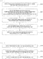
- FIG. 1 is a flowchart illustrating a manufacturing method of a tire integrated electronic device according to an embodiment of the invention.
- Step S10 of positioning an electronic device mockup portion inside a first mold unit and a second mold unit can be set to be fulfilled.
- FIG. 2 is a flowchart illustrating a step of positioning the electronic device mockup portion according to the embodiment of the invention.
- Step S10 of positioning the electronic device mockup portion inside the first mold unit and the second mold unit first, step S11 of preparing the first mold unit and the second mold unit can be fulfilled.
- the first mold unit and the second mold unit can be provided in a state of being divided into two parts in an up-down direction or in a right-left direction.
- the first mold unit includes a first mold body and a mold inlet.
- the first mold body can form a body of the first mold unit.
- the mold inlet is provided on an inner side of the first mold body and can be provided to allow unvulcanized rubber to be injected into an inside of the mold through the mold inlet.
- the second mold unit forms a lower part of the mold and includes a second mold body and a mold groove.
- the second mold body can form a body of the second mold unit and can be coupled to a lower part of the first mold body.
- the mold groove is provided on an inner side of the second mold body and can be provided to accommodate the electronic device mockup portion 110 (refer to FIG. 4 ) inside.
- the specific shape of the mold groove can be provided as a shape of a rubber mount unit 120 (refer to FIG. 4 ) which will be described.
- Step S12 of positioning the electronic device mockup portion at an inner center of the first mold unit and the second mold unit can be fulfilled.
- the electronic device mockup portion 110 can be provided to have an antenna portion located at a position corresponding to an antenna hole forming portion 130.
- a position of an antenna portion of an electronic device unit 140 can be marked on the electronic device mockup portion 110.
- the electronic device mockup portion 110 provided as described above can be provided to have the marked antenna portion located at a position corresponding to the antenna hole forming portion 130.
- the antenna hole forming portion 130 enables the position corresponding to the antenna portion not to be enclosed by the unvulcanized rubber which encloses the electronic device unit 140 such that an antenna hole 123 can be formed in the rubber mount unit 120.
- a guide portion can be attached to an upper part of the electronic device mockup portion 110, the guide portion being provided to guide so that the electronic device mockup portion 110 is temporarily located at a center of the mold groove and to conveniently install the electronic device mockup portion 110 after vulcanization.
- Step S12 of positioning the electronic device mockup portion at the inner center of the first mold unit and the second mold unit Step S13 of closing the first mold unit and the second mold unit can be fulfilled.
- Step S20 of performing injection molding or compression molding by injecting unvulcanized rubber inside the first mold unit and the second mold unit such that the unvulcanized rubber encloses the electronic device mockup portion can be fulfilled.
- FIG. 3 is a flowchart illustrating the step of performing injection molding or compression molding according to the embodiment of the invention.
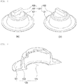
- FIG. 4 is a perspective view illustrating the tire integrated electronic device in a state where the electronic device mockup portion according to the embodiment of the invention is mounted.
- FIG. 5 is a side view illustrating the tire integrated electronic device in the state where the electronic device mockup portion according to the embodiment of the invention is mounted
- FIG. 6 is a perspective view illustrating the tire integrated electronic device according to the embodiment of the invention.
- Step S20 of performing injection molding or compression molding by injecting the unvulcanized rubber inside the first mold unit and the second mold unit such that the unvulcanized rubber encloses the electronic device mockup portion Step S21 of injecting the unvulcanized rubber inside the first mold unit and inside the second mold unit can be fulfilled.
- Step S21 of injecting the unvulcanized rubber inside the first mold unit and inside the second mold unit the unvulcanized rubber can be injected through the mold inlet such that the unvulcanized rubber can fill an inside of the mold groove.
- the unvulcanized rubber can be made of any one of natural rubber, synthetic rubber, a mixture of natural rubber and synthetic rubber, or a polymer.
- Step S21 of injecting the unvulcanized rubber inside the first mold unit and inside the second mold unit the unvulcanized rubber can fill insides of the first mold unit and the second mold unit to enclose the electronic device mockup portion 110, but can be provided to enclose the electronic device mockup portion 110 except for the antenna hole forming portion 130 located at an upper part of the electronic device mockup portion 110 and a position corresponding to an insertion hole 124 located at a lower part of the electronic device mockup portion 110.
- the rubber mount unit 120 can be molded to have the insertion hole 124, through which the electronic device unit 140 is to be inserted, at a lower part of the rubber mount unit.
- Step S22 of maintaining a preset vulcanization temperature for a preset vulcanization time so as to induce a crosslinking reaction in the injected unvulcanized rubber can be fulfilled.
- Step S22 of maintaining the preset vulcanization temperature for the preset vulcanization time so as to induce the crosslinking reaction in the injected unvulcanized rubber the vulcanization temperature can be set in a range of 120°C to 160°C, and the vulcanization time can be set in a range of one minute to 30 minutes.
- the vulcanization time can be set until the unvulcanized rubber is completely vulcanized.
- the rubber mount unit 120 formed through vulcanization can be formed to include a bottom body 121, a side body 122, the antenna hole 123, and the insertion hole 124.
- the bottom body 121 can be formed to enclose a lower part of the electronic device unit 140 except for a portion of the insertion hole 124, and the bottom body 121 can be molded to have an area which is equal to or larger than 110% of a bottom area of the electronic device unit 140.
- the circular bottom body 121 is illustrated; however, the shape thereof is not limited thereto, and the bottom body can be formed into a polygonal shape.
- the side body 122 can be formed to be extended upward from the bottom body 121 and can be formed to enclose a side surface of the electronic device unit 140.
- the antenna hole 123 can be provided on an inner side of an upper part of the side body 122, and the antenna hole 123 enables an antenna and a pressure measuring portion of the electronic device unit 140 to be exposed to the outside such that sensing sensitivity is not degraded.
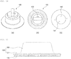
- FIG. 7 is a perspective view illustrating the rubber mount unit according to the embodiment of the invention in a state of being vertically cut.
- FIG. 8 illustrates a photograph of an actual rubber mount unit according to the embodiment of the invention in a state of being vertically cut.
- the insertion hole 124 can be formed in the bottom body 121.
- the insertion hole 124 can be formed to have a multi-step structure such that an air layer is formed between the electronic device unit 140 and the inner liner without a surface-to-surface contact between a bottom surface of the electronic device unit 140 and a surface of the inner liner.
- the electronic device unit 140 when the electronic device unit 140 is in contact with the surface of the inner liner of the tire, the electronic device unit 140 is finely moved due to inertia and vibration during running of a vehicle.
- the surface of the inner liner is damaged due to friction caused from movement of the electronic device unit 140.
- the insertion hole 124 is formed between the surface of the inner liner and the electronic device unit 140 such that the air layer is formed therebetween, it is possible to achieve an effect that an impact transmitted from a tread is reduced by additionally passing through an air layer medium in addition to a solid medium between the tread and the inner liner.
- the rubber mount unit 120 can be formed to have a bottom, that is, the bottom body 121 having a thickness of 0.5 mm to 3.0 mm.
- the electronic device unit 140 inserted into the insertion hole 124 and the surface of the inner liner can come into contact with each other due to vibration caused by running or the like, and thus the inner liner can be damaged.
- the bottom body 121 has a thickness of more than 3.0 mm or is too thick, a weight of a tire integrated electronic device 100 increases, an influence of inertia on the tire integrated electronic device increases, and thus the inner liner can be damaged.
- the thickness of the bottom body 121 it is desirable to limit the thickness of the bottom body 121 to 3.0 mm.
- the insertion hole 124 can be formed to have an area as large as 60% to 95% of the bottom area of the electronic device unit 140 such that the above-described effects can be maximized.
- the area of the bottom body 121 is to be equal to or larger than 110% of the bottom area of the electronic device unit 140, and the insertion hole 124 is to be formed to have the area as large as 60% to 95% of the bottom area such that the air layer for reducing an impact can be formed.
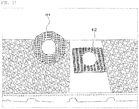
- FIG. 9 illustrates photographs of an integrated electronic device without having the insertion hole according to the embodiment of the invention, the photographs being taken before and after an evaluation is performed.
- FIG. 9 is a photograph illustrating a state where an electronic device 1 in the related art without having the insertion hole 124 is attached to an inner liner.
- the electronic device 1 in the related art does not have the insertion hole 124 formed at a lower part of the electronic device unit 140, the impact is not cushioned, and thus a problem arises in that the inner liner is damaged due to vibration.
- the insertion hole 124 is formed to form the air layer between the inner liner and the electronic device unit 140, the impact is cushioned, and thus it is possible to inhibit the inner liner from being damaged.
- the insertion hole 124 inhibits heat of the inner liner from being directly transmitted to the electronic device unit 140, and the air layer further increases a heat insulation effect, an effect of improving heat resistance of the electronic device unit 140 is achieved.
- Step S30 of unmolding the rubber mount unit molded to enclose the electronic device mockup portion can be fulfilled.
- Step S30 of unmolding the rubber mount unit molded to enclose the electronic device mockup portion the electronic device mockup portion 110 can be unmolded from the rubber mount unit 120.
- FIG. 10 is a photograph illustrating the tire integrated electronic device according to the embodiment of the invention.
- Step S40 of inserting the electronic device unit into a lower end portion of the unmolded rubber mount unit can be fulfilled.
- Step S40 of inserting the electronic device unit into the lower end portion of the unmolded rubber mount unit the electronic device unit 140 can be inserted into the rubber mount unit 120 through the insertion hole 124.
- Step S50 of attaching the electronic device unit-inserted rubber mount unit to the inner liner of the tire can be fulfilled.
- Step S50 of attaching the electronic device unit-inserted rubber mount unit to the inner liner of the tire the rubber mount unit 120 can be attached to the inner liner by an adhesive or glue.
- Examples of the adhesive can include an instant adhesive, a silicone adhesive series, or a glue which exhibit 50% attachment strength within 10 minutes after attachment.
- FIG. 11 is a side view illustrating a rubber mount unit attached with Velcro according to the embodiment of the invention.
- FIG. 12 is a photograph illustrating the Velcro according to the embodiment of the invention.
- Step S50 of attaching the electronic device unit-inserted rubber mount unit to the inner liner of the tire the rubber mount unit 120 can be attached to the inner liner by the Velcro.
- Step S50 of attaching the electronic device unit-inserted rubber mount unit to the inner liner of the tire first, first Velcro 151 can be provided to be coupled to a lower part of the rubber mount unit 120. Then, second Velcro 152 which can be attached to the first Velcro 151 of the rubber mount unit 120 can be coupled to an inner side of the inner liner.
- the rubber mount unit 120 can be attached to the inner liner by using the first Velcro 151 and the second Velcro 152.
- the rubber mount unit 120 can be fastened to the inner liner by using a hook.
- the invention provided as described above can avoid the problem of causing the inner liner to be damaged by the electronic device unit 140 since the electronic device unit 140 is attached in a state of being separated from the surface of the inner liner and the insertion hole 124 is formed such that the air layer is formed between the inner liner and the electronic device unit 140.
- the electronic device unit 140 is integrated with the rubber mount unit 120, it is possible to perform history management by tracking a tire, as long as the rubber mount unit 120 is not detached from the inner liner by artificial means after primary attachment.
- the electronic device unit 140 measures acceleration, and the acceleration has directionality, it is difficult to transmit an accurate value, when a direction of the electronic device unit 140 is incorrect.
- the electronic device unit 140 is integrated with the rubber mount unit 120, it is possible to avoid a problem of incorrect measurement of information such as acceleration due to a change in direction of the electronic device unit 140.
- the invention according to the configuration described above has the following effects. Since the electronic device unit is attached in a state of being separated from the surface of the inner liner and the insertion hole is formed such that air layer is formed between the inner liner and the electronic device unit, it is possible to avoid a problem of causing the electronic device unit to damage the inner liner.
- the electronic device unit is integrated with the rubber mount unit, it is possible to perform history management by tracking a tire, as long as the rubber mount unit is not detached by artificial means after primary attachment.
- the electronic device unit measures acceleration, and the acceleration has directionality, it is difficult to transmit an accurate value, when a direction is incorrect.
- the electronic device unit is integrated with the rubber mount unit, it is possible to avoid a problem of incorrect measurement due to a change in direction of the electronic device unit.
Landscapes
- Engineering & Computer Science (AREA)
- Mechanical Engineering (AREA)
- Manufacturing & Machinery (AREA)
- Moulds For Moulding Plastics Or The Like (AREA)
Abstract
Description
- The present invention relates to a manufacturing method of a tire integrated electronic device, and more specifically, a manufacturing method of a tire integrated electronic device by which the electronic device is inhibited from damaging a tire by being detached from a rubber mount.
- Korean Patent Registration No.
0614520 - United States Patent No.
6788192 - United States Patent No.
8561659 - United States Patent Application No.
2009-0071249 - United States Patent No.
9016118 - United States Patent No.
9016339 - United States Patent Application No.
2006-0158340 - United States Patent Application No.
2014-0144210 - Patent Literature 0001: Korean Patent Registration No.
0614520 - An object of the invention to solve such problems is to provide a manufacturing method of a tire integrated electronic device by which the electronic device is inhibited from damaging a tire by being detached from a rubber mount.
- Technical objects to be achieved by the invention are not limited to the technical object mentioned above, and the following description enables other unmentioned technical objects to be clearly understood by a person of ordinary skill in the art to which the invention belongs.
- According to a configuration of the invention to achieve the object described above, there is provided a manufacturing method of a tire integrated electronic device, including: a) step of positioning an electronic device mockup portion inside a first mold unit and a second mold unit; b) step of performing injection molding or compression molding by injecting unvulcanized rubber inside the first mold unit and the second mold unit such that the unvulcanized rubber encloses the electronic device mockup portion; c) step of unmolding a rubber mount unit molded to enclose the electronic device mockup portion; d) step of inserting an electronic device unit into a lower end portion of the unmolded rubber mount unit; and e) step of attaching the electronic device unit-inserted rubber mount unit to an inner liner of a tire. The rubber mount unit is molded to have an insertion hole, through which the electronic device unit is to be inserted, at a lower portion of the rubber mount unit.
- According to an embodiment of the invention, the a) step may include: a1) step of preparing the first mold unit and the second mold unit; a2) step of positioning the electronic device mockup portion at an inner center of the first mold unit and the second mold unit; and a3) step of closing the first mold unit and the second mold unit.
- According to the embodiment of the invention, in the a2) step, the electronic device mockup portion may be provided to have an antenna portion located at a position corresponding to an antenna hole forming portion.
- According to the embodiment of the invention, the b) step may include: b1) step of injecting the unvulcanized rubber inside the first mold unit and inside the second mold unit; and b2) step of maintaining a preset vulcanization temperature for a preset vulcanization time so as to induce a crosslinking reaction in the injected unvulcanized rubber.
- According to the embodiment of the invention, in the b1) step, the unvulcanized rubber may fill insides of the first mold unit and the second mold unit to enclose the electronic device mockup portion, and the unvulcanized rubber may be provided to enclose the electronic device mockup portion except for the antenna hole forming portion located at an upper part of the electronic device mockup portion and a position corresponding to the insertion hole located at a lower part of the electronic device mockup portion.
- According to the embodiment of the invention, in the b2) step, the vulcanization temperature may be set in a range of 120°C to 160°C, and the vulcanization time may be set in a range of one minute to 30 minutes.
- According to the embodiment of the invention, in the c) step, the electronic device mockup portion may be unmolded from the rubber mount unit.
- According to the embodiment of the invention, in the d) step, the electronic device unit may be inserted into the rubber mount unit through the insertion hole.
- According to the embodiment of the invention, the insertion hole may be formed to have a multi-step structure such that an air layer is formed between the electronic device unit and the inner liner without a surface-to-surface contact between a bottom surface of the electronic device unit and a surface of the inner liner.
- According to the embodiment of the invention, the rubber mount unit may be formed to have a bottom having a thickness of 0.5 mm to 3.0 mm.
- According to the embodiment of the invention, the insertion hole may be formed to have an area as large as 60% to 95% of a bottom area of the electronic device unit.
- According to another configuration of the invention to achieve the object described above, there is provided an integrated electronic device that is manufactured in accordance with the manufacturing method of a tire integrated electronic device.
- According to still another configuration of the invention to achieve the object described above, there is provided a tire attached with an integrated electronic device that is manufactured in accordance with the manufacturing method of a tire integrated electronic device.
-
-
FIG. 1 is a flowchart illustrating a manufacturing method of a tire integrated electronic device according to an embodiment of the invention; -
FIG. 2 is a flowchart illustrating a step of positioning an electronic device mockup portion according to the embodiment of the invention; -
FIG. 3 is a flowchart illustrating a step of performing injection molding or compression molding according to the embodiment of the invention; -
FIG. 4 is a perspective view illustrating the tire integrated electronic device in a state where the electronic device mockup portion according to the embodiment of the invention is mounted; -
FIG. 5 is a side view illustrating the tire integrated electronic device in the state where the electronic device mockup portion according to the embodiment of the invention is mounted; -
FIG. 6 is a perspective view illustrating the tire integrated electronic device according to the embodiment of the invention; -
FIG. 7 is a perspective view illustrating a state where a rubber mount unit according to the embodiment of the invention in a state of being vertically cut; -
FIG. 8 illustrates a photograph of an actual rubber mount unit according to the embodiment of the invention in a state of being vertically cut; -
FIG. 9 illustrates photographs of an integrated electronic device without having an insertion hole according to the embodiment of the invention, the photographs being taken before and after an evaluation is performed; -
FIG. 10 illustrates photographs of the tire integrated electronic device according to the embodiment of the invention; -
FIG. 11 is a side view illustrating a rubber mount unit attached with Velcro according to the embodiment of the invention; and -
FIG. 12 is a photograph illustrating the Velcro according to the embodiment of the invention. - Hereinafter, the invention is to be described with reference to the accompanying drawings. However, the invention can be realized as various different examples, and thus is not limited to embodiments described here. Besides, a part irrelevant to the description is omitted from the drawings in order to clearly describe the invention, and similar reference signs are assigned to similar parts through the entire specification.
- In the entire specification, a case where a certain part is "connected to (attached to, in contact with, or coupled to)" another part means not only a case where the parts are "directly connected" to each other, but also a case where the parts are "indirectly connected" to each other with another member interposed therebetween. In addition, a case where a certain part "comprises" a certain configurational element does not mean that another configurational element is excluded but means that the other configurational element can be further included, unless specifically described otherwise.
- Terms used in this specification are only used to describe a specific embodiment and are not intentionally used to limit the invention thereto. A singular form of a word includes a plural meaning of the word, unless obviously implied otherwise in context. In this specification, words such as "to comprise" or "to have" are understood to specify that a feature, a number, a step, an operation, a configurational element, a member, or a combination thereof described in the specification is present and not to exclude presence or a possibility of addition of one or more other features, numbers, steps, operations, configurational elements, members, or combinations thereof in advance.
- Hereinafter, embodiments of the invention will be described in detail with reference to the accompanying drawings.
-
FIG. 1 is a flowchart illustrating a manufacturing method of a tire integrated electronic device according to an embodiment of the invention. - In the manufacturing method of a tire integrated electronic device, first, Step S10 of positioning an electronic device mockup portion inside a first mold unit and a second mold unit can be set to be fulfilled.
-
FIG. 2 is a flowchart illustrating a step of positioning the electronic device mockup portion according to the embodiment of the invention. - With further reference to
FIG. 2 , in Step S10 of positioning the electronic device mockup portion inside the first mold unit and the second mold unit, first, step S11 of preparing the first mold unit and the second mold unit can be fulfilled. - The first mold unit and the second mold unit can be provided in a state of being divided into two parts in an up-down direction or in a right-left direction.
- More specifically, the first mold unit includes a first mold body and a mold inlet.
- The first mold body can form a body of the first mold unit.
- The mold inlet is provided on an inner side of the first mold body and can be provided to allow unvulcanized rubber to be injected into an inside of the mold through the mold inlet.
- The second mold unit forms a lower part of the mold and includes a second mold body and a mold groove.
- The second mold body can form a body of the second mold unit and can be coupled to a lower part of the first mold body.
- The mold groove is provided on an inner side of the second mold body and can be provided to accommodate the electronic device mockup portion 110 (refer to
FIG. 4 ) inside. - The specific shape of the mold groove can be provided as a shape of a rubber mount unit 120 (refer to
FIG. 4 ) which will be described. - After Step S11 of preparing the first mold unit and the second mold unit, Step S12 of positioning the electronic device mockup portion at an inner center of the first mold unit and the second mold unit can be fulfilled.
- In Step S12 of positioning the electronic device mockup portion at the inner center of the first mold unit and the second mold unit, the electronic
device mockup portion 110 can be provided to have an antenna portion located at a position corresponding to an antennahole forming portion 130. - Specifically, a position of an antenna portion of an
electronic device unit 140 can be marked on the electronicdevice mockup portion 110. The electronicdevice mockup portion 110 provided as described above can be provided to have the marked antenna portion located at a position corresponding to the antennahole forming portion 130. - The antenna
hole forming portion 130 enables the position corresponding to the antenna portion not to be enclosed by the unvulcanized rubber which encloses theelectronic device unit 140 such that anantenna hole 123 can be formed in therubber mount unit 120. - In addition, a guide portion can be attached to an upper part of the electronic
device mockup portion 110, the guide portion being provided to guide so that the electronicdevice mockup portion 110 is temporarily located at a center of the mold groove and to conveniently install the electronicdevice mockup portion 110 after vulcanization. - After Step S12 of positioning the electronic device mockup portion at the inner center of the first mold unit and the second mold unit, Step S13 of closing the first mold unit and the second mold unit can be fulfilled.
- After Step S10 of positioning the electronic device mockup portion inside the first mold unit and the second mold unit, Step S20 of performing injection molding or compression molding by injecting unvulcanized rubber inside the first mold unit and the second mold unit such that the unvulcanized rubber encloses the electronic device mockup portion can be fulfilled.
-
FIG. 3 is a flowchart illustrating the step of performing injection molding or compression molding according to the embodiment of the invention.FIG. 4 is a perspective view illustrating the tire integrated electronic device in a state where the electronic device mockup portion according to the embodiment of the invention is mounted. - In addition,
FIG. 5 is a side view illustrating the tire integrated electronic device in the state where the electronic device mockup portion according to the embodiment of the invention is mounted, andFIG. 6 is a perspective view illustrating the tire integrated electronic device according to the embodiment of the invention. - With further reference to
FIGS. 3 to 6 , in Step S20 of performing injection molding or compression molding by injecting the unvulcanized rubber inside the first mold unit and the second mold unit such that the unvulcanized rubber encloses the electronic device mockup portion, Step S21 of injecting the unvulcanized rubber inside the first mold unit and inside the second mold unit can be fulfilled. - In Step S21 of injecting the unvulcanized rubber inside the first mold unit and inside the second mold unit, the unvulcanized rubber can be injected through the mold inlet such that the unvulcanized rubber can fill an inside of the mold groove.
- Here, the unvulcanized rubber can be made of any one of natural rubber, synthetic rubber, a mixture of natural rubber and synthetic rubber, or a polymer.
- In Step S21 of injecting the unvulcanized rubber inside the first mold unit and inside the second mold unit, the unvulcanized rubber can fill insides of the first mold unit and the second mold unit to enclose the electronic
device mockup portion 110, but can be provided to enclose the electronicdevice mockup portion 110 except for the antennahole forming portion 130 located at an upper part of the electronicdevice mockup portion 110 and a position corresponding to aninsertion hole 124 located at a lower part of the electronicdevice mockup portion 110. - In other words, the
rubber mount unit 120 can be molded to have theinsertion hole 124, through which theelectronic device unit 140 is to be inserted, at a lower part of the rubber mount unit. - After Step S21 of injecting the unvulcanized rubber inside the first mold unit and inside the second mold unit, Step S22 of maintaining a preset vulcanization temperature for a preset vulcanization time so as to induce a crosslinking reaction in the injected unvulcanized rubber can be fulfilled.
- In Step S22 of maintaining the preset vulcanization temperature for the preset vulcanization time so as to induce the crosslinking reaction in the injected unvulcanized rubber, the vulcanization temperature can be set in a range of 120°C to 160°C, and the vulcanization time can be set in a range of one minute to 30 minutes.
- The vulcanization time can be set until the unvulcanized rubber is completely vulcanized.
- In Step S22 of maintaining the preset vulcanization temperature for the preset vulcanization time so as to induce the crosslinking reaction in the injected unvulcanized rubber, the
rubber mount unit 120 formed through vulcanization can be formed to include abottom body 121, aside body 122, theantenna hole 123, and theinsertion hole 124. - The
bottom body 121 can be formed to enclose a lower part of theelectronic device unit 140 except for a portion of theinsertion hole 124, and thebottom body 121 can be molded to have an area which is equal to or larger than 110% of a bottom area of theelectronic device unit 140. - The circular
bottom body 121 is illustrated; however, the shape thereof is not limited thereto, and the bottom body can be formed into a polygonal shape. - The
side body 122 can be formed to be extended upward from thebottom body 121 and can be formed to enclose a side surface of theelectronic device unit 140. - The
antenna hole 123 can be provided on an inner side of an upper part of theside body 122, and theantenna hole 123 enables an antenna and a pressure measuring portion of theelectronic device unit 140 to be exposed to the outside such that sensing sensitivity is not degraded. -
FIG. 7 is a perspective view illustrating the rubber mount unit according to the embodiment of the invention in a state of being vertically cut.FIG. 8 illustrates a photograph of an actual rubber mount unit according to the embodiment of the invention in a state of being vertically cut. - With further reference to
FIGS. 7 and8 , theinsertion hole 124 can be formed in thebottom body 121. - Specifically, the
insertion hole 124 can be formed to have a multi-step structure such that an air layer is formed between theelectronic device unit 140 and the inner liner without a surface-to-surface contact between a bottom surface of theelectronic device unit 140 and a surface of the inner liner. - Specifically, when the
electronic device unit 140 is in contact with the surface of the inner liner of the tire, theelectronic device unit 140 is finely moved due to inertia and vibration during running of a vehicle. Here, when long-time running is performed, the surface of the inner liner is damaged due to friction caused from movement of theelectronic device unit 140. - However, when a space is formed between the
electronic device unit 140 and the inner liner by theinsertion hole 124, the friction is not generated, and thus the surface of the inner liner is not to be damaged by theelectronic device unit 140. - In particular, when the
insertion hole 124 is formed between the surface of the inner liner and theelectronic device unit 140 such that the air layer is formed therebetween, it is possible to achieve an effect that an impact transmitted from a tread is reduced by additionally passing through an air layer medium in addition to a solid medium between the tread and the inner liner. - Besides, the
rubber mount unit 120 can be formed to have a bottom, that is, thebottom body 121 having a thickness of 0.5 mm to 3.0 mm. - When the
bottom body 121 has a thickness of less than 0.5 mm, theelectronic device unit 140 inserted into theinsertion hole 124 and the surface of the inner liner can come into contact with each other due to vibration caused by running or the like, and thus the inner liner can be damaged. - In addition, when the
bottom body 121 has a thickness of more than 3.0 mm or is too thick, a weight of a tire integratedelectronic device 100 increases, an influence of inertia on the tire integrated electronic device increases, and thus the inner liner can be damaged. - Hence, it is desirable to limit the thickness of the
bottom body 121 to 3.0 mm. - In addition, the
insertion hole 124 can be formed to have an area as large as 60% to 95% of the bottom area of theelectronic device unit 140 such that the above-described effects can be maximized. - In other words, the area of the
bottom body 121 is to be equal to or larger than 110% of the bottom area of theelectronic device unit 140, and theinsertion hole 124 is to be formed to have the area as large as 60% to 95% of the bottom area such that the air layer for reducing an impact can be formed. -
FIG. 9 illustrates photographs of an integrated electronic device without having the insertion hole according to the embodiment of the invention, the photographs being taken before and after an evaluation is performed. - (a) of
FIG. 9 is a photograph illustrating a state where anelectronic device 1 in the related art without having theinsertion hole 124 is attached to an inner liner. - As illustrated in (b) of
FIG. 9 , when theelectronic device 1 in the related art is evaluated after running, it is possible to see that one side of a rubber mount portion is pushed and swollen. - In addition, as illustrated in (c) of
FIG. 9 , when a surface of the inner liner is checked after theelectronic device 1 in the related art is removed, it is possible to see that the inner liner is damaged to the extent that a carcass cord can be seen. - As described above, since the
electronic device 1 in the related art does not have theinsertion hole 124 formed at a lower part of theelectronic device unit 140, the impact is not cushioned, and thus a problem arises in that the inner liner is damaged due to vibration. - However, according to the invention, since the
insertion hole 124 is formed to form the air layer between the inner liner and theelectronic device unit 140, the impact is cushioned, and thus it is possible to inhibit the inner liner from being damaged. - In addition, according to the invention, since the
insertion hole 124 inhibits heat of the inner liner from being directly transmitted to theelectronic device unit 140, and the air layer further increases a heat insulation effect, an effect of improving heat resistance of theelectronic device unit 140 is achieved. - After Step S20 of performing injection molding or compression molding by injecting the unvulcanized rubber inside the first mold unit and the second mold unit such that the unvulcanized rubber encloses the electronic device mockup portion, Step S30 of unmolding the rubber mount unit molded to enclose the electronic device mockup portion can be fulfilled.
- In Step S30 of unmolding the rubber mount unit molded to enclose the electronic device mockup portion, the electronic
device mockup portion 110 can be unmolded from therubber mount unit 120. -
FIG. 10 is a photograph illustrating the tire integrated electronic device according to the embodiment of the invention. - With reference to
FIG. 10 , after Step S30 of unmolding the rubber mount unit molded to enclose the electronic device mockup portion, Step S40 of inserting the electronic device unit into a lower end portion of the unmolded rubber mount unit can be fulfilled. - In Step S40 of inserting the electronic device unit into the lower end portion of the unmolded rubber mount unit, the
electronic device unit 140 can be inserted into therubber mount unit 120 through theinsertion hole 124. - After Step S40 of inserting the electronic device unit into the lower end portion of the unmolded rubber mount unit, Step S50 of attaching the electronic device unit-inserted rubber mount unit to the inner liner of the tire can be fulfilled.
- In Step S50 of attaching the electronic device unit-inserted rubber mount unit to the inner liner of the tire, the
rubber mount unit 120 can be attached to the inner liner by an adhesive or glue. - Examples of the adhesive can include an instant adhesive, a silicone adhesive series, or a glue which exhibit 50% attachment strength within 10 minutes after attachment.
-
FIG. 11 is a side view illustrating a rubber mount unit attached with Velcro according to the embodiment of the invention.FIG. 12 is a photograph illustrating the Velcro according to the embodiment of the invention. - With reference to
FIGS. 11 and12 , in Step S50 of attaching the electronic device unit-inserted rubber mount unit to the inner liner of the tire, therubber mount unit 120 can be attached to the inner liner by the Velcro. - Specifically, in Step S50 of attaching the electronic device unit-inserted rubber mount unit to the inner liner of the tire, first,
first Velcro 151 can be provided to be coupled to a lower part of therubber mount unit 120. Then,second Velcro 152 which can be attached to thefirst Velcro 151 of therubber mount unit 120 can be coupled to an inner side of the inner liner. - Next, the
rubber mount unit 120 can be attached to the inner liner by using thefirst Velcro 151 and thesecond Velcro 152. - On the other hand, the
rubber mount unit 120 can be fastened to the inner liner by using a hook. - The invention provided as described above can avoid the problem of causing the inner liner to be damaged by the
electronic device unit 140 since theelectronic device unit 140 is attached in a state of being separated from the surface of the inner liner and theinsertion hole 124 is formed such that the air layer is formed between the inner liner and theelectronic device unit 140. - In addition, it is possible to avoid a problem of causing the
electronic device unit 140 to be detached from therubber mount unit 120 and damage a tire. - In addition, since the
electronic device unit 140 is integrated with therubber mount unit 120, it is possible to perform history management by tracking a tire, as long as therubber mount unit 120 is not detached from the inner liner by artificial means after primary attachment. - In addition, it is possible to avoid a problem of detachment of the
electronic device unit 140 due to incorrect installation of theelectronic device unit 140. - In addition, since the
electronic device unit 140 measures acceleration, and the acceleration has directionality, it is difficult to transmit an accurate value, when a direction of theelectronic device unit 140 is incorrect. However, when theelectronic device unit 140 is integrated with therubber mount unit 120, it is possible to avoid a problem of incorrect measurement of information such as acceleration due to a change in direction of theelectronic device unit 140. - The invention according to the configuration described above has the following effects. Since the electronic device unit is attached in a state of being separated from the surface of the inner liner and the insertion hole is formed such that air layer is formed between the inner liner and the electronic device unit, it is possible to avoid a problem of causing the electronic device unit to damage the inner liner.
- It is possible to avoid a problem of causing the electronic device unit to be detached from the rubber mount unit and damage a tire.
- In addition, since the electronic device unit is integrated with the rubber mount unit, it is possible to perform history management by tracking a tire, as long as the rubber mount unit is not detached by artificial means after primary attachment.
- In addition, it is possible to avoid a problem of detachment of an electronic device unit due to incorrect installation of the electronic device unit.
- In addition, since the electronic device unit measures acceleration, and the acceleration has directionality, it is difficult to transmit an accurate value, when a direction is incorrect. However, when the electronic device unit is integrated with the rubber mount unit, it is possible to avoid a problem of incorrect measurement due to a change in direction of the electronic device unit.
- In addition, it is possible to perform molding regardless of a shape of an electronic device.
- Effects of the invention are construed not to be limited to the above-mentioned effects but to include every effect that can be derived from configurations of the invention described in the detailed description of the preferred embodiments and claims of the invention.
- The description of the invention described above is provided as an example, and a person of ordinary skill in the art to which the invention belongs can understand that it is possible to easily modify the invention to another embodiment without changing the technical idea or essential feature of the invention. Therefore, the embodiments described above are provided to be understood as exemplified examples in every aspect and not as examples limiting the invention. For example, the configurational elements described in singular forms can be realized in a distributed manner. Similarly, the configurational elements described in a distributed manner can be realized in a combined manner.
- The scope of the invention has to be represented by the claims to be described below, and every modification or modified embodiment derived from the meaning and scope of the claims and an equivalent concept of the claims have to be construed to be included in the scope of the invention.
Claims (13)
- A manufacturing method of a tire integrated electronic device, comprising:a) step of positioning an electronic device mockup portion inside a first mold unit and a second mold unit;b) step of performing injection molding or compression molding by injecting unvulcanized rubber inside the first mold unit and the second mold unit such that the unvulcanized rubber encloses the electronic device mockup portion;c) step of unmolding a rubber mount unit molded to enclose the electronic device mockup portion;d) step of inserting an electronic device unit into a lower end portion of the unmolded rubber mount unit; ande) step of attaching the electronic device unit-inserted rubber mount unit to an inner liner of a tire,wherein the rubber mount unit is molded to have an insertion hole, through which the electronic device unit is to be inserted, at a lower portion of the rubber mount unit.
- The manufacturing method of a tire integrated electronic device according to claim 1,
wherein a) includes:a1) step of preparing the first mold unit and the second mold unit;a2) step of positioning the electronic device mockup portion at an inner center of the first mold unit and the second mold unit; anda3) step of closing the first mold unit and the second mold unit. - The manufacturing method of a tire integrated electronic device according to claim 2,
wherein, in the a2) step, the electronic device mockup portion is provided to have an antenna portion located at a position corresponding to an antenna hole forming portion. - The manufacturing method of a tire integrated electronic device according to one of claims 1 to 3,
wherein the b) step includes:b1) step of injecting the unvulcanized rubber inside the first mold unit and inside the second mold unit; andb2) step of maintaining a preset vulcanization temperature for a preset vulcanization time so as to induce a crosslinking reaction in the injected unvulcanized rubber. - The manufacturing method of a tire integrated electronic device according to claim 4,
wherein, in the b1) step,
the unvulcanized rubber fills insides of the first mold unit and the second mold unit to enclose the electronic device mockup portion, and
the unvulcanized rubber is provided to enclose the electronic device mockup portion except for the antenna hole forming portion located at an upper part of the electronic device mockup portion and a position corresponding to the insertion hole located at a lower part of the electronic device mockup portion. - The manufacturing method of a tire integrated electronic device according to claim 4 or 5,
wherein, in the b2) step, the vulcanization temperature is set in a range of 120°C to 160°C, and the vulcanization time is set in a range of one minute to 30 minutes. - The manufacturing method of a tire integrated electronic device according to one of claims 1 to 6,
wherein, in the c) step, the electronic device mockup portion is unmolded from the rubber mount unit. - The manufacturing method of a tire integrated electronic device according to one of claims 1 to 7,
wherein, in the d) step, the electronic device unit is inserted into the rubber mount unit through the insertion hole. - The manufacturing method of a tire integrated electronic device according to one of claims 1 to 8,
wherein the insertion hole is formed to have a multi-step structure such that an air layer is formed between the electronic device unit and the inner liner without a surface-to-surface contact between a bottom surface of the electronic device unit and a surface of the inner liner. - The manufacturing method of a tire integrated electronic device according to claim 9,
wherein the rubber mount unit is formed to have a bottom having a thickness of 0.5 mm to 3.0 mm. - The manufacturing method of a tire integrated electronic device according to claim 9 or 10,
wherein the insertion hole is formed to have an area as large as 60% to 95% of a bottom area of the electronic device unit. - An integrated electronic device that is manufactured in accordance with the manufacturing method of a tire integrated electronic device according to one of claims 1 to 11.
- A tire attached with an integrated electronic device that is manufactured in accordance with the manufacturing method of a tire integrated electronic device according to one of claims 1 to 11.
Applications Claiming Priority (1)
| Application Number | Priority Date | Filing Date | Title |
|---|---|---|---|
| KR1020200019159A KR102218154B1 (en) | 2020-02-17 | 2020-02-17 | Manufacturing method of tire integrated electronic device |
Publications (1)
| Publication Number | Publication Date |
|---|---|
| EP3865291A1 true EP3865291A1 (en) | 2021-08-18 |
Family
ID=74666572
Family Applications (1)
| Application Number | Title | Priority Date | Filing Date |
|---|---|---|---|
| EP21157601.2A Pending EP3865291A1 (en) | 2020-02-17 | 2021-02-17 | Manufacturing method of tire integrated electronic device, integrated electronic device obtained thereby and tire |
Country Status (4)
| Country | Link |
|---|---|
| US (1) | US20210252816A1 (en) |
| EP (1) | EP3865291A1 (en) |
| KR (1) | KR102218154B1 (en) |
| CN (1) | CN113263679B (en) |
Families Citing this family (3)
| Publication number | Priority date | Publication date | Assignee | Title |
|---|---|---|---|---|
| USD962097S1 (en) * | 2019-09-12 | 2022-08-30 | Suzhou Sate Auto Electronic Co., Ltd. | Bandage type tire pressure monitoring sensor |
| USD974204S1 (en) * | 2019-09-12 | 2023-01-03 | Suzhou Sate Auto Electronic Co., Ltd. | Wall-mounted tire pressure monitoring sensor |
| USD947050S1 (en) * | 2020-12-15 | 2022-03-29 | The Goodyear Tire & Rubber Company | Tire sensor container |
Citations (11)
| Publication number | Priority date | Publication date | Assignee | Title |
|---|---|---|---|---|
| US20020174925A1 (en) * | 1998-02-10 | 2002-11-28 | Wilson Paul B. | Electronic monitoring device and patch assembly |
| US6788192B2 (en) | 2001-01-12 | 2004-09-07 | The Yokohama Rubber Co., Ltd. | Transponder for tire, tire with transponder and manufacturing method of tire with transponder |
| KR100614520B1 (en) | 1998-12-04 | 2006-08-22 | 브릿지스톤/화이어스톤인코포레이티드 | Method of attaching sensitive electronic equipment to the inner surface of a tire |
| DE102007030231A1 (en) * | 2007-06-29 | 2009-01-08 | Continental Aktiengesellschaft | Tire module for vehicle, has electronic module held in box over circular form closure, and air cushion and lower plate, which are arranged between lower side of electronic module and inner side of tire for absorbing mechanical stresses |
| US20090071249A1 (en) | 2004-11-19 | 2009-03-19 | The Yokohama Rubber Co., Ltd. | Acceleration sensor-attached tire |
| WO2013098712A1 (en) * | 2011-12-29 | 2013-07-04 | Pirelli Tyre S.P.A. | Monitoring device for tyres for vehicle wheels, tyre for vehicle wheels provided with said monitoring device, and method for installing an electronic unit in said tyre |
| US8561659B2 (en) | 2009-08-24 | 2013-10-22 | The Goodyear Tire & Rubber Company | Tire and electronic device assembly |
| US20140144210A1 (en) | 2011-05-23 | 2014-05-29 | The Yokohama Rubber Co., Ltd. | Pneumatic tire |
| US9016118B2 (en) | 2010-12-22 | 2015-04-28 | Caterpillar Inc. | Mounting structure |
| US9016339B2 (en) | 2010-07-27 | 2015-04-28 | The Yokohama Rubber Co., Ltd. | Pneumatic tire |
| EP3492289A2 (en) * | 2017-11-30 | 2019-06-05 | Hankook Tire Co., Ltd. | Container structure for attaching sensors to tires and method of manufacturing tire container structure |
Family Cites Families (11)
| Publication number | Priority date | Publication date | Assignee | Title |
|---|---|---|---|---|
| DE69916115T2 (en) * | 1998-08-03 | 2009-10-01 | The Goodyear Tire & Rubber Co., Akron | ASSEMBLY OF TRANSPONDERS IN AIR TIRES |
| DE102006004707A1 (en) * | 2005-02-03 | 2006-09-14 | Continental Teves Ag & Co. Ohg | Holding unit for joining pressure sensor to tire, comprising space for vibration absorbing air cushion |
| JP2006234578A (en) * | 2005-02-24 | 2006-09-07 | Bridgestone Corp | Attaching member, pneumatic tire, and manufacturing method for pneumatic tire |
| FR2919226B1 (en) * | 2007-07-24 | 2009-10-09 | Michelin Soc Tech | TIRE EQUIPPED FOR ATTACHING AN OBJECT TO ITS WALL AND METHOD OF MANUFACTURING THE SAME. |
| WO2016060851A1 (en) * | 2014-10-16 | 2016-04-21 | Bridgestone Americas Tire Operations, Llc | Tire having embedded electronic device affixed with adhesive |
| FR3029832B1 (en) * | 2014-12-15 | 2017-10-20 | Michelin & Cie | SUPPORT INSTALLATION METHOD FOR ELECTRONIC PNEUMATIC MODULE |
| KR101760872B1 (en) * | 2015-08-24 | 2017-07-24 | 한국타이어 주식회사 | Pneumatic tire comprising sensor patch and method for manufacturing the same |
| KR101781698B1 (en) * | 2015-11-13 | 2017-09-25 | 한국타이어 주식회사 | A tire sensor installing structure comprising a sensor patch and a manufacturing method thereof |
| KR101925774B1 (en) * | 2017-11-30 | 2018-12-10 | 한국타이어 주식회사 | Method of manufacturing tire integral type container structure |
| JP6909146B2 (en) * | 2017-12-15 | 2021-07-28 | 株式会社ブリヂストン | How to attach rubber members and how to manufacture tires |
| KR102080442B1 (en) * | 2019-06-28 | 2020-02-21 | 한국타이어앤테크놀로지 주식회사 | Tire integrated with electronic device and manufacturing method thereof |
-
2020
- 2020-02-17 KR KR1020200019159A patent/KR102218154B1/en active IP Right Grant
-
2021
- 2021-02-11 US US17/173,866 patent/US20210252816A1/en active Pending
- 2021-02-17 EP EP21157601.2A patent/EP3865291A1/en active Pending
- 2021-02-18 CN CN202110190138.2A patent/CN113263679B/en active Active
Patent Citations (12)
| Publication number | Priority date | Publication date | Assignee | Title |
|---|---|---|---|---|
| US20020174925A1 (en) * | 1998-02-10 | 2002-11-28 | Wilson Paul B. | Electronic monitoring device and patch assembly |
| US20060158340A1 (en) | 1998-02-10 | 2006-07-20 | Bridgestone/Firestone North America Tire, Llc | Electronic monitoring device and patch assembly |
| KR100614520B1 (en) | 1998-12-04 | 2006-08-22 | 브릿지스톤/화이어스톤인코포레이티드 | Method of attaching sensitive electronic equipment to the inner surface of a tire |
| US6788192B2 (en) | 2001-01-12 | 2004-09-07 | The Yokohama Rubber Co., Ltd. | Transponder for tire, tire with transponder and manufacturing method of tire with transponder |
| US20090071249A1 (en) | 2004-11-19 | 2009-03-19 | The Yokohama Rubber Co., Ltd. | Acceleration sensor-attached tire |
| DE102007030231A1 (en) * | 2007-06-29 | 2009-01-08 | Continental Aktiengesellschaft | Tire module for vehicle, has electronic module held in box over circular form closure, and air cushion and lower plate, which are arranged between lower side of electronic module and inner side of tire for absorbing mechanical stresses |
| US8561659B2 (en) | 2009-08-24 | 2013-10-22 | The Goodyear Tire & Rubber Company | Tire and electronic device assembly |
| US9016339B2 (en) | 2010-07-27 | 2015-04-28 | The Yokohama Rubber Co., Ltd. | Pneumatic tire |
| US9016118B2 (en) | 2010-12-22 | 2015-04-28 | Caterpillar Inc. | Mounting structure |
| US20140144210A1 (en) | 2011-05-23 | 2014-05-29 | The Yokohama Rubber Co., Ltd. | Pneumatic tire |
| WO2013098712A1 (en) * | 2011-12-29 | 2013-07-04 | Pirelli Tyre S.P.A. | Monitoring device for tyres for vehicle wheels, tyre for vehicle wheels provided with said monitoring device, and method for installing an electronic unit in said tyre |
| EP3492289A2 (en) * | 2017-11-30 | 2019-06-05 | Hankook Tire Co., Ltd. | Container structure for attaching sensors to tires and method of manufacturing tire container structure |
Also Published As
| Publication number | Publication date |
|---|---|
| CN113263679A (en) | 2021-08-17 |
| US20210252816A1 (en) | 2021-08-19 |
| KR102218154B1 (en) | 2021-02-23 |
| CN113263679B (en) | 2023-04-07 |
Similar Documents
| Publication | Publication Date | Title |
|---|---|---|
| EP3865291A1 (en) | Manufacturing method of tire integrated electronic device, integrated electronic device obtained thereby and tire | |
| AU745710B2 (en) | Method and apparatus for bonding an active tag to a patch and tire | |
| EP1321315B1 (en) | Electronic tire tag removably insertable into a tire | |
| US9242516B2 (en) | Power component and instrumented tyre | |
| CA2484779C (en) | Monitoring device and patch assembly | |
| JP4441058B2 (en) | Combination of pneumatic tire monitoring device and patch and installation method thereof | |
| US8596117B2 (en) | Attachment patch for mounting various devices | |
| CN112770922B (en) | Functional component, structure for attaching functional component to tire, and tire | |
| US9022086B2 (en) | Pneumatic tire | |
| US20030000297A1 (en) | Transmitter of tire condition monitoring apparatus and method for manufacturing transmitter of tire condition monitoring apparatus | |
| EP3756909A1 (en) | Tire integrated with electronic device and manufacturing method thereof | |
| BRPI0520146A2 (en) | vehicle wheel tire, detection device, method of mounting a detection device, and methods of mounting a device on a tire, and of manufacturing a vehicle wheel tire | |
| JP2006511393A (en) | Tire with tag | |
| US7543490B2 (en) | Tire comprising a force measuring device having a rigid stem | |
| JP2003285612A (en) | Tire equipped with measurement device | |
| EP1268225A1 (en) | Attachment patch for mounting an electronic monitoring device to the inside of a pneumatic tire | |
| WO2016099633A1 (en) | Attachment patch for mounting devices | |
| EP3390118A1 (en) | Attachment mechanism for tire-mounted sensors | |
| WO2015045459A1 (en) | Pneumatic tire, and method of manufacturing same | |
| KR102113071B1 (en) | Method for manufacturing electronic device in integral form | |
| BRPI0901765B1 (en) | pressure measuring device and unit comprising a pressure measuring device and a mold for vulcanizing a tire rubber | |
| CA3153951C (en) | Assembly for an inner tube | |
| AU2012201759B2 (en) | Tire with tire tag | |
| JP2006103486A (en) | Pneumatic tire and method for mounting transponder on pneumatic tire |
Legal Events
| Date | Code | Title | Description |
|---|---|---|---|
| PUAI | Public reference made under article 153(3) epc to a published international application that has entered the european phase |
Free format text: ORIGINAL CODE: 0009012 |
|
| STAA | Information on the status of an ep patent application or granted ep patent |
Free format text: STATUS: REQUEST FOR EXAMINATION WAS MADE |
|
| 17P | Request for examination filed |
Effective date: 20210217 |
|
| AK | Designated contracting states |
Kind code of ref document: A1 Designated state(s): AL AT BE BG CH CY CZ DE DK EE ES FI FR GB GR HR HU IE IS IT LI LT LU LV MC MK MT NL NO PL PT RO RS SE SI SK SM TR |
|
| STAA | Information on the status of an ep patent application or granted ep patent |
Free format text: STATUS: EXAMINATION IS IN PROGRESS |
|
| 17Q | First examination report despatched |
Effective date: 20230418 |
|
| GRAP | Despatch of communication of intention to grant a patent |
Free format text: ORIGINAL CODE: EPIDOSNIGR1 |
|
| STAA | Information on the status of an ep patent application or granted ep patent |
Free format text: STATUS: GRANT OF PATENT IS INTENDED |
|
| INTG | Intention to grant announced |
Effective date: 20240802 |