WO2015045459A1 - Pneumatic tire, and method of manufacturing same - Google Patents
Pneumatic tire, and method of manufacturing same Download PDFInfo
- Publication number
- WO2015045459A1 WO2015045459A1 PCT/JP2014/060735 JP2014060735W WO2015045459A1 WO 2015045459 A1 WO2015045459 A1 WO 2015045459A1 JP 2014060735 W JP2014060735 W JP 2014060735W WO 2015045459 A1 WO2015045459 A1 WO 2015045459A1
- Authority
- WO
- WIPO (PCT)
- Prior art keywords
- tire
- mechanical fastener
- pneumatic tire
- fastener member
- pneumatic
- Prior art date
Links
- 238000004519 manufacturing process Methods 0.000 title claims abstract description 24
- 238000000465 moulding Methods 0.000 claims abstract description 25
- 238000004073 vulcanization Methods 0.000 claims description 35
- 238000000034 method Methods 0.000 claims description 24
- 230000003014 reinforcing effect Effects 0.000 claims description 10
- 230000008569 process Effects 0.000 claims description 9
- 238000010276 construction Methods 0.000 claims description 6
- 230000002787 reinforcement Effects 0.000 claims description 4
- 229940123973 Oxygen scavenger Drugs 0.000 claims description 3
- 239000002274 desiccant Substances 0.000 claims description 3
- 238000000825 ultraviolet detection Methods 0.000 claims description 2
- 230000002093 peripheral effect Effects 0.000 abstract description 11
- 230000000694 effects Effects 0.000 description 14
- 238000010586 diagram Methods 0.000 description 9
- 239000000463 material Substances 0.000 description 8
- 239000012779 reinforcing material Substances 0.000 description 7
- 238000012360 testing method Methods 0.000 description 7
- 238000009864 tensile test Methods 0.000 description 6
- 238000003860 storage Methods 0.000 description 4
- 239000011358 absorbing material Substances 0.000 description 3
- 230000009471 action Effects 0.000 description 3
- 239000011324 bead Substances 0.000 description 3
- 239000000470 constituent Substances 0.000 description 3
- 238000009826 distribution Methods 0.000 description 3
- 238000000691 measurement method Methods 0.000 description 3
- 238000005096 rolling process Methods 0.000 description 3
- AFCARXCZXQIEQB-UHFFFAOYSA-N N-[3-oxo-3-(2,4,6,7-tetrahydrotriazolo[4,5-c]pyridin-5-yl)propyl]-2-[[3-(trifluoromethoxy)phenyl]methylamino]pyrimidine-5-carboxamide Chemical compound O=C(CCNC(=O)C=1C=NC(=NC=1)NCC1=CC(=CC=C1)OC(F)(F)F)N1CC2=C(CC1)NN=N2 AFCARXCZXQIEQB-UHFFFAOYSA-N 0.000 description 2
- 239000004809 Teflon Substances 0.000 description 2
- 229920006362 Teflon® Polymers 0.000 description 2
- 230000008901 benefit Effects 0.000 description 2
- 230000015572 biosynthetic process Effects 0.000 description 2
- 230000000052 comparative effect Effects 0.000 description 2
- 230000006835 compression Effects 0.000 description 2
- 238000007906 compression Methods 0.000 description 2
- 230000007423 decrease Effects 0.000 description 2
- 230000006866 deterioration Effects 0.000 description 2
- 238000005304 joining Methods 0.000 description 2
- 239000002184 metal Substances 0.000 description 2
- 230000000149 penetrating effect Effects 0.000 description 2
- 229920005989 resin Polymers 0.000 description 2
- 239000011347 resin Substances 0.000 description 2
- 229920003002 synthetic resin Polymers 0.000 description 2
- 239000000057 synthetic resin Substances 0.000 description 2
- 229920001875 Ebonite Polymers 0.000 description 1
- NIPNSKYNPDTRPC-UHFFFAOYSA-N N-[2-oxo-2-(2,4,6,7-tetrahydrotriazolo[4,5-c]pyridin-5-yl)ethyl]-2-[[3-(trifluoromethoxy)phenyl]methylamino]pyrimidine-5-carboxamide Chemical compound O=C(CNC(=O)C=1C=NC(=NC=1)NCC1=CC(=CC=C1)OC(F)(F)F)N1CC2=C(CC1)NN=N2 NIPNSKYNPDTRPC-UHFFFAOYSA-N 0.000 description 1
- 230000000903 blocking effect Effects 0.000 description 1
- 230000008859 change Effects 0.000 description 1
- 238000007796 conventional method Methods 0.000 description 1
- 230000008878 coupling Effects 0.000 description 1
- 238000010168 coupling process Methods 0.000 description 1
- 238000005859 coupling reaction Methods 0.000 description 1
- 230000003247 decreasing effect Effects 0.000 description 1
- 238000001514 detection method Methods 0.000 description 1
- 230000001747 exhibiting effect Effects 0.000 description 1
- 230000002452 interceptive effect Effects 0.000 description 1
- 238000011835 investigation Methods 0.000 description 1
- NJPPVKZQTLUDBO-UHFFFAOYSA-N novaluron Chemical compound C1=C(Cl)C(OC(F)(F)C(OC(F)(F)F)F)=CC=C1NC(=O)NC(=O)C1=C(F)C=CC=C1F NJPPVKZQTLUDBO-UHFFFAOYSA-N 0.000 description 1
- 230000035515 penetration Effects 0.000 description 1
- 238000012545 processing Methods 0.000 description 1
- 239000012744 reinforcing agent Substances 0.000 description 1
- 239000012783 reinforcing fiber Substances 0.000 description 1
- 238000013040 rubber vulcanization Methods 0.000 description 1
- 238000000926 separation method Methods 0.000 description 1
- 238000005728 strengthening Methods 0.000 description 1
- 238000012546 transfer Methods 0.000 description 1
Images


Classifications
-
- B—PERFORMING OPERATIONS; TRANSPORTING
- B29—WORKING OF PLASTICS; WORKING OF SUBSTANCES IN A PLASTIC STATE IN GENERAL
- B29D—PRODUCING PARTICULAR ARTICLES FROM PLASTICS OR FROM SUBSTANCES IN A PLASTIC STATE
- B29D30/00—Producing pneumatic or solid tyres or parts thereof
- B29D30/0061—Accessories, details or auxiliary operations not otherwise provided for
-
- B—PERFORMING OPERATIONS; TRANSPORTING
- B29—WORKING OF PLASTICS; WORKING OF SUBSTANCES IN A PLASTIC STATE IN GENERAL
- B29D—PRODUCING PARTICULAR ARTICLES FROM PLASTICS OR FROM SUBSTANCES IN A PLASTIC STATE
- B29D30/00—Producing pneumatic or solid tyres or parts thereof
- B29D30/02—Solid tyres ; Moulds therefor
-
- B—PERFORMING OPERATIONS; TRANSPORTING
- B29—WORKING OF PLASTICS; WORKING OF SUBSTANCES IN A PLASTIC STATE IN GENERAL
- B29D—PRODUCING PARTICULAR ARTICLES FROM PLASTICS OR FROM SUBSTANCES IN A PLASTIC STATE
- B29D30/00—Producing pneumatic or solid tyres or parts thereof
- B29D30/06—Pneumatic tyres or parts thereof (e.g. produced by casting, moulding, compression moulding, injection moulding, centrifugal casting)
- B29D30/0601—Vulcanising tyres; Vulcanising presses for tyres
- B29D30/0662—Accessories, details or auxiliary operations
-
- B—PERFORMING OPERATIONS; TRANSPORTING
- B60—VEHICLES IN GENERAL
- B60C—VEHICLE TYRES; TYRE INFLATION; TYRE CHANGING; CONNECTING VALVES TO INFLATABLE ELASTIC BODIES IN GENERAL; DEVICES OR ARRANGEMENTS RELATED TO TYRES
- B60C17/00—Tyres characterised by means enabling restricted operation in damaged or deflated condition; Accessories therefor
- B60C17/04—Tyres characterised by means enabling restricted operation in damaged or deflated condition; Accessories therefor utilising additional non-inflatable supports which become load-supporting in emergency
-
- B—PERFORMING OPERATIONS; TRANSPORTING
- B60—VEHICLES IN GENERAL
- B60C—VEHICLE TYRES; TYRE INFLATION; TYRE CHANGING; CONNECTING VALVES TO INFLATABLE ELASTIC BODIES IN GENERAL; DEVICES OR ARRANGEMENTS RELATED TO TYRES
- B60C19/00—Tyre parts or constructions not otherwise provided for
-
- B—PERFORMING OPERATIONS; TRANSPORTING
- B60—VEHICLES IN GENERAL
- B60C—VEHICLE TYRES; TYRE INFLATION; TYRE CHANGING; CONNECTING VALVES TO INFLATABLE ELASTIC BODIES IN GENERAL; DEVICES OR ARRANGEMENTS RELATED TO TYRES
- B60C19/00—Tyre parts or constructions not otherwise provided for
- B60C19/002—Noise damping elements provided in the tyre structure or attached thereto, e.g. in the tyre interior
-
- B—PERFORMING OPERATIONS; TRANSPORTING
- B60—VEHICLES IN GENERAL
- B60C—VEHICLE TYRES; TYRE INFLATION; TYRE CHANGING; CONNECTING VALVES TO INFLATABLE ELASTIC BODIES IN GENERAL; DEVICES OR ARRANGEMENTS RELATED TO TYRES
- B60C19/00—Tyre parts or constructions not otherwise provided for
- B60C19/003—Balancing means attached to the tyre
-
- B—PERFORMING OPERATIONS; TRANSPORTING
- B60—VEHICLES IN GENERAL
- B60C—VEHICLE TYRES; TYRE INFLATION; TYRE CHANGING; CONNECTING VALVES TO INFLATABLE ELASTIC BODIES IN GENERAL; DEVICES OR ARRANGEMENTS RELATED TO TYRES
- B60C23/00—Devices for measuring, signalling, controlling, or distributing tyre pressure or temperature, specially adapted for mounting on vehicles; Arrangement of tyre inflating devices on vehicles, e.g. of pumps or of tanks; Tyre cooling arrangements
- B60C23/02—Signalling devices actuated by tyre pressure
- B60C23/04—Signalling devices actuated by tyre pressure mounted on the wheel or tyre
- B60C23/0491—Constructional details of means for attaching the control device
- B60C23/0493—Constructional details of means for attaching the control device for attachment on the tyre
-
- G—PHYSICS
- G01—MEASURING; TESTING
- G01N—INVESTIGATING OR ANALYSING MATERIALS BY DETERMINING THEIR CHEMICAL OR PHYSICAL PROPERTIES
- G01N21/00—Investigating or analysing materials by the use of optical means, i.e. using sub-millimetre waves, infrared, visible or ultraviolet light
- G01N21/17—Systems in which incident light is modified in accordance with the properties of the material investigated
- G01N21/25—Colour; Spectral properties, i.e. comparison of effect of material on the light at two or more different wavelengths or wavelength bands
- G01N21/31—Investigating relative effect of material at wavelengths characteristic of specific elements or molecules, e.g. atomic absorption spectrometry
- G01N21/33—Investigating relative effect of material at wavelengths characteristic of specific elements or molecules, e.g. atomic absorption spectrometry using ultraviolet light
-
- B—PERFORMING OPERATIONS; TRANSPORTING
- B29—WORKING OF PLASTICS; WORKING OF SUBSTANCES IN A PLASTIC STATE IN GENERAL
- B29D—PRODUCING PARTICULAR ARTICLES FROM PLASTICS OR FROM SUBSTANCES IN A PLASTIC STATE
- B29D30/00—Producing pneumatic or solid tyres or parts thereof
- B29D30/0061—Accessories, details or auxiliary operations not otherwise provided for
- B29D2030/0072—Attaching fasteners to tyres, e.g. patches, in order to connect devices to tyres
-
- B—PERFORMING OPERATIONS; TRANSPORTING
- B60—VEHICLES IN GENERAL
- B60C—VEHICLE TYRES; TYRE INFLATION; TYRE CHANGING; CONNECTING VALVES TO INFLATABLE ELASTIC BODIES IN GENERAL; DEVICES OR ARRANGEMENTS RELATED TO TYRES
- B60C19/00—Tyre parts or constructions not otherwise provided for
- B60C2019/004—Tyre sensors other than for detecting tyre pressure
Definitions
- the present invention relates to a pneumatic tire and a manufacturing method thereof.
- the mechanical fastener material is bonded to the tire inner peripheral surface with a very high bonding strength.
- the present invention relates to a pneumatic tire and a method for manufacturing the pneumatic tire.
- a tire tag for example, a high-frequency identification tag
- a chip or the like is attached to a raw tire inner liner using a so-called hook-and-loop fastener such as a hook-and-loop fastener or a hook-and-hook fastener.
- An attachment method has been proposed (Patent Document 1).
- a pneumatic tire in which a surface fastener is vulcanized and bonded to a region corresponding to a tread portion on the tire inner surface, and a sound absorbing material is attached to the tire inner surface via the surface fastener (Patent Document 2). ).
- the engagement state of the individual engaging elements of the hook-and-loop fastener is not ideal because the inner peripheral surface of the pneumatic tire is an annular curved surface. Some of them floated at the center or the like, and the resulting engagement force may vary in size (positional variation within the tire, variation between tires). Therefore, the engagement force as expected may not be obtained.
- deformation and compression due to rolling at high speed under relatively high temperature conditions are repeated for a long time, so that partial physical deterioration occurs and partial physical deterioration occurs. Due to the progress, the engaging force of the entire surface fastener is deteriorated / decreased with time, and therefore it may be difficult to maintain the desired engaging force over a long period of time.
- the hook-and-loop fastener is preferable in that it can be engaged in a plane shape without causing a slight positional deviation in the mounting, but on the other hand, when the functional object to be mounted is a measuring instrument, etc. Then, the mounting position is required to be more accurate and accurate, and there are some functional objects that are not suitable for mounting with hook-and-loop fasteners.
- the inventors of the present invention have previously obtained a large engagement force and little variation (positional variation within a tire, variation between tires), and a relatively high temperature. Even under severe use conditions in which deformation and compression associated with tire rolling at low and high speeds are repeated for a long time, the engagement force is less likely to deteriorate or decrease over time, and the desired engagement force can be maintained over a long period of time.
- a so-called hook or snap called a mechanical fastener is joined to the tire inner surface, and various objects having a desired function are attached via the mechanical fastener (Patent Document 3, 4 and 5).
- Patent Document 3 typically, as described in the claims of Patent Document 3, one of a pair of mechanical fasteners that can be separated into two, such as a hook or a snap, is provided on the tire inner surface.
- a pneumatic tire having a tool has been proposed (Claims of Patent Document 3 (Claim 1)). More specifically, the one fastener is composed of at least two components, and the two components are fixed by sandwiching a tire member or a tire reinforcing material to constitute the one fastener. A pneumatic tire is proposed (Claims of Patent Document 3 (Claim 2)).
- one of the mechanical fasteners attached to the inner surface of the tire it is composed of at least two parts, and these two parts are fixed with a tire member or a tire reinforcement interposed therebetween, and the one fastener is used. If the constituents were used, the fixing was stronger, the durability was better, and they were even better.
- the object to be attached is a large object, it is necessary to attach the mechanical fastener so that it protrudes from the inner surface of the tire to some extent, and the object is a heavy object. In some cases, the bonding force between the tire inner surface and the mechanical fastener may not be sufficient.
- the height of the most protruding portion from the tire inner surface is preferably 0 mm to 3 mm (paragraph 0029 of Patent Document 3), which is higher than that. Fasteners with protruding heights are not recommended.
- the vulcanization bladder develops (expands) in the tire, but the bladder surface and the tire surface move relative to each other in the in-plane direction and rub against each other.
- the tool receives a lateral force in a specific direction and is tilted and fixed. As a result, the durability of the fastener is reduced.
- an object of the present invention is to provide a pneumatic tire provided with a mechanical fastener member for attaching an object to the inner surface of the pneumatic tire. It is in providing the pneumatic tire joined to the tire inner peripheral surface, and the manufacturing method of this pneumatic tire.
- the pneumatic tire of the present invention that achieves the above-described object has the following configuration (1).
- a mechanical fastener member that is one of the mechanical fasteners that can be separated into two members and is fixed to protrude toward the tire lumen side is provided on the inner surface of the tire.
- the pneumatic tire of the present invention preferably has any one of the following configurations (2) to (12).
- the mechanical fastener member has a bottom embedded in the tire inner surface, a protrusion height from the tire inner surface of 3 mm or more, and a maximum diameter of 8 mm or more.
- the mechanical fastener member includes two or more components, and the two or more components are fixed to each other with a tire member or a tire reinforcing material fixed to the tire interposed therebetween.
- the mechanical fastener member is composed of two or more components, and the two or more components are fixed to each other with a tire reinforcing member fixed to the tire interposed therebetween. None, and the inner surface of the tire around the mechanical fastener member forms a recess, and when the tire inner surface is viewed in plan view from the vertical direction, the entire recess is the outer edge line of the tire reinforcing member.
- the pneumatic tire as described in any one of (1) to (4) above, which is located inside.
- a pneumatic tire characterized in that a detachable collar member is loaded in a space formed between a peripheral tire inner surface. (7) The collar member is loaded before the vulcanization molding step of the pneumatic tire, and the pneumatic tire is vulcanized and molded with the collar member loaded.
- the collar member may be provided with another color member after the pneumatic tire is vulcanized and molded in the state before the pneumatic tire is vulcanized and molded.
- the pneumatic tire according to (6) wherein the pneumatic tire is a collar member reloaded in a space formed by removing the member and removing the other collar member.
- An object having another mechanical fastener that engages with the one mechanical fastener on the tire inner surface is fixed to the tire inner surface by engaging the two fasteners.
- the inner surface of the tire around the mechanical fastener member forms a recess, and when the tire inner surface is viewed in plan view from the vertical direction, the outer edge line of the object has the recess at all positions.
- the object having the other fastener is (a) an electronic circuit including a sensor, (b) a balance weight, (c) a run-flat core, (d) an oxygen scavenger, a desiccant and / or ultraviolet rays.
- the manufacturing method of the pneumatic tire of the present invention which achieves the above-mentioned object has the following configuration (13).
- (13) A pneumatic tire having a mechanical fastener member which is one of the mechanical fasteners separable into two members and which is fixed to the tire inner surface is fixed to the tire inner surface.
- the mechanical fastener member is disposed on the inner surface of the green tire before being vulcanized and protruded toward the tire lumen, and the vicinity of the protruding tip of the protruding portion of the mechanical fastener member And a color member filling the space in a space formed between the inner surface of the green tire around the mechanical fastener member and subjected to a vulcanization molding process, and after the vulcanization molding, the air
- a method for producing a pneumatic tire wherein the collar member is removed before the start of use of the tire.
- the mechanical fastener material has a very high bonding strength.
- a pneumatic tire that can be bonded to the inner peripheral surface of a tire is provided, whereby the attached object is less likely to fall, and the function of the object can be stably exhibited over a long period of time.
- the effect of the present invention obtained by the first aspect of the present invention is clearer even though the protruding height of the fastener member is high.
- the pneumatic tire of the present invention which can be exhibited as a product can be realized.
- the pneumatic tire of the present invention that can further enhance the effect of the present invention according to claim 1 can be realized.
- the mechanical fastener protruding by the detachable collar is physically protected while having the effect of the present invention according to claim 1. If the collar is loaded before being used in the vulcanization molding process of the pneumatic tire, the pressure of the bladder is reduced due to the presence of the collar. And the temperature can be effectively applied to the vicinity of the mounting base of the mechanical fastener. As a result, vulcanization molding in the vicinity of the mounting root can be performed more effectively, and in that respect, high fixing strength of the mechanical fastener can be obtained (Claims 7 and 8).
- a pneumatic tire in which a desired object is attached to a predetermined position on the tire inner surface by realizing a large fixing strength and excellent durability.
- the effect can be obtained regardless of the size of the desired object.
- the weight or volume of an object having a desired function to be attached to the tire inner surface is large to some extent, the effect is remarkable.
- a pneumatic vehicle for construction vehicles in which various objects having a desired function are attached to a predetermined position on the inner surface of the tire so as to be detachably mounted with high fixing strength and excellent durability.
- pneumatic tires for construction vehicles are large in size and weight and heavy in vehicles, it is important to always monitor and measure the air pressure in the tire lumen. Thus, the effects of the present invention can be sufficiently obtained.
- a pneumatic tire provided with a mechanical fastener member for attaching an object to the inner surface of the pneumatic tire, in particular, the inner peripheral surface of the tire with a very high bonding strength is provided.
- a method for producing a pneumatic tire joined to a tire is provided, whereby the attached object is less likely to fall, and the function of the object can be stably exhibited over a long period of time.
- a method of manufacturing a pneumatic tire is provided.
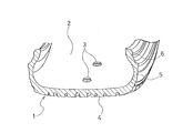
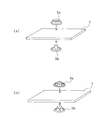
- FIG. 1 is a partial cross-sectional perspective view showing an embodiment of the pneumatic tire of the present invention.
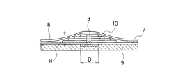
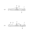
- FIG. 2 is a model diagram for explaining an example of a method for producing a pneumatic tire according to the present invention.
- the mechanical fastener is fixed around the mechanical fastener member fixed to the tire inner surface.
- a state in which vulcanization molding is performed using a bladder in a state where a collar member is filled in a space formed between a protruding tip portion of the fastener member and a tire inner surface around the mechanical fastener member It is sectional drawing which showed.
- FIG. 3 is shown for comparison with an example of the method of manufacturing the pneumatic tire of the present invention shown in FIG.
- FIG. 5 illustrates an embodiment of the pneumatic tire according to the present invention, and is an enlarged view of a main part showing the periphery of a mechanical fastener member provided on the inner surface of the tire.
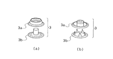
- FIGS. 6 (a) and 6 (b) are enlarged views of a main part for explaining an embodiment of the pneumatic tire of the present invention, and 2 shown in FIGS. 4 (a) and 4 (b), respectively. It is a principal part enlarged view explaining the state which fixes one component part on both sides of a tire member or a tire reinforcing material, and comprises one fastener member.
- FIG. 7 illustrates an embodiment of the pneumatic tire according to the present invention, and is an enlarged view of a main part showing the periphery of a mechanical fastener member provided on the inner surface of the tire.
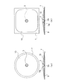
- FIGS. 8A to 8D are longitudinal sectional views showing various embodiments of the color member that can be used in the method for producing the pneumatic tire of the present invention.
- FIGS. 10 (a) and 10 (b) show various embodiments of the color member that can be used in the method for producing the pneumatic tire of the present invention.
- a plan view is shown in the upper part of the drawing, and a longitudinal sectional view is shown in the lower part.
- FIGS. 10 (a) and 10 (b) illustrate an embodiment of the pneumatic tire of the present invention, and an enlarged side view of a main part showing the periphery of a mechanical fastener member provided on the inner surface of the tire.
- FIG. 11 is a cross-sectional view schematically illustrating a preferable shape of the collar member that can be used in the method for manufacturing the pneumatic tire of the present invention.
- FIGS. 12 (a) and 12 (b) are perspective views illustrating a method for measuring the fixing strength of the mechanical fastener member employed in the present invention.
- FIGS. 13A and 13B are schematic diagrams for explaining a method for measuring the fixing strength of the mechanical fastener member employed in the present invention. A method of engaging a tool is shown.
- FIG. 14 is a schematic diagram illustrating a method for measuring the fixing strength of a mechanical fastener member employed in the present invention, and is a model example of a structure of a tensile test shaft jig engaged with the mechanical fastener. It is shown in.
- FIG. 15 shows a model of the fixing position of the mechanical fastener member employed in the example, and is a schematic diagram of a cross section in the tire meridian direction.
- the pneumatic tire 1 of the present invention is fixed to a tire inner surface 2 by being one member of mechanical fasteners that can be separated into two members and protruding toward the tire lumen.
- the mechanical fastener member 3 is provided, and the fixing strength of the mechanical fastener member 3 is 0.1 to 100 (N / mm 2 ).
- 4 is a tread portion
- 5 is a sidewall portion
- 6 is a bead portion.
- the mechanical fastener is a pair that can be separated into two fastener members and can be physically engaged again, and this engagement and separation can be repeated freely.
- the structure may be basically the same as that described in Patent Documents 3 to 5 described above.
- a typical example is a mechanical fastener called a hook or snap. That is, generally in the clothing industry and the like, more specifically, it is a generic name for snap buttons, ring snaps, ring hooks, American snaps, American hooks, eyelet hooks, spring hooks and jumper hooks.
- the engagement portion is a small area (for example, preferably about 1 to 115 mm 2, more preferably about 4 to 90 mm 2 ). This means the fastener. That is, for example, even engagement in a small area of about 1 to 115 mm 2 means that strong engagement is achieved by a mechanical male-female structure or the like, which itself has a known structure. Good.
- the material can be formed using a metal, a synthetic resin, or a hard rubber.
- examples of the attachment position of the mechanical fastener member 3 include, for example, the vicinity of the tire equator on the tire inner surface as shown in FIG. 1, but are not particularly limited.
- the bead portion 6 is less affected by such influence.
- it may be provided on the tire inner surface near the sidewall portion 5. If the fixing strength of the mechanical fastener member 3 is 0.1 to 100 (N / mm 2 ), according to the knowledge of the present inventors, it is possible to fix and fix almost all the objects to be mounted in the tire lumen. It can respond enough.
- a preferable range of the fixing strength is 0.2 to 50 (N / mm 2 ).
- a space portion X that makes the action of the bladder 8 difficult to occur is generated in the vicinity Y of the root of the mechanical fastener member 3, and the vulcanization molding is not successfully performed on the tire inner surface in the vicinity. This is considered to be a reason why high fixing strength cannot be obtained. In particular, when the protruding height H of the mechanical fastener member 3 is large, such a phenomenon is considered to be remarkable. In addition, the bladder may be damaged at the location, which may impede vulcanization molding.
- the present inventors load the collar member 10 into the space X portion described above and perform vulcanization molding as shown in FIG. It has been found that the pressure and heat of the bladder can be sufficiently transmitted to the vicinity and the formation of the mechanical fastener member 3 exhibiting high fixing strength can be realized.
- 2 and 3 7 is a tire structural member or tire reinforcing material
- 8 is a bladder
- 9 is an inner liner
- 10 is a collar member.
- the details of the collar member 10 will be described later, it is important that the collar member 10 is formed of a material that can sufficiently transmit the pressure and heat from the bladder to the green tire to be vulcanized.
- the effect of the present invention is that the bottom part of the mechanical fastener member 3 is embedded in the tire inner surface, the protruding height H from the tire inner surface is 3 mm or more, and the maximum part diameter D is 8 mm or more. If so, it will be particularly prominent. This is because when the protruding height H is 3 mm or more, the effect of using the collar member is remarkably exhibited, and when the maximum diameter D is less than 8 mm, the protruding height is high. Therefore, it is not preferable because it is in a direction that makes it difficult to obtain a high fixing strength.
- the mechanical fastener member 3 is preferably composed of two or more components 3a and 3b, as shown in FIGS.
- the two or more components 3a and 3b are fixed to each other with a tire member or a tire reinforcement 7 fixed to the tire interposed therebetween to form the mechanical fastener member 3, and the mechanical fastener member 3
- it is preferably fixed to the tire reinforcing material 7 fixed to the tire member or the tire by vulcanization adhesion. This is because the mechanical coupling force between the component parts 3a and 3b causes an increase in the fixing force to the tire member or the tire reinforcing member 7 fixed to the tire.
- These two components 3a and 3b are integrally fixed to form one fastener member 3 of the pair of mechanical fastener members 3, and on the tire inner surface 2 as shown in FIG. The member 3a is mainly exposed.
- the tire member 7 refers to a constituent member of a tire made of rubber, resin, or the like, and specifically corresponds to an inner liner, a carcass, or the like.
- a rubber layer, a rubberized reinforcing fiber layer or a resin layer used for the purpose of being sandwiched between both members 3a or 3b of the fastener, and a plurality of them are laminated.
- a reinforcing layer may be additionally provided as the reinforcing member 7, and such a configuration is generally preferable because the air blocking performance in the tire is improved.
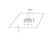
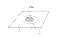
- the tire inner surface 2 has a recess 11 as shown in FIG.
- 12 indicates an outer edge line of the recess.
- the recess 11 can be formed by applying a higher pressure than the surroundings to the location using the collar member 10. Since the inner surface of the tire has a curvature, the formation of the recesses may interfere with each other when the mounting object has a flat bottom surface. It is effective to form the recess 11 around the fastener member 3.
- the degree of the dent is preferably 0.2 mm or more and 3 mm or less in the dent depth G shown in FIG. 10 (b). In order to prevent interference, it is preferable that the dent has a flat shape with no curvature. .
- the recessed portion 11 has a high fixing strength when the entire inner surface of the recessed portion 11 is located inside the outer edge line of the tire reinforcing member 7 (FIG. 6) when the tire inner surface is viewed in plan view from the vertical direction. It is preferable in maintaining.
- the color member used in the vulcanization molding process of the pneumatic tire of the present invention is removed from the tire after the vulcanization molding is completed. That is, when the tire is used, it does not become a constituent member of the tire. However, in the space formed between the protruding tip of the mechanical fastener member and the tire inner surface around the mechanical fastener member, the protruding tip of the mechanical fastener member and the mechanical fastener In order to physically protect the entire member, a detachable collar member may be loaded and used for distribution and storage of the tire.
- the color member at the time of distribution / storage may be the one used as it is in the vulcanization molding process of the pneumatic tire, or another color member that is particularly suitable for protection use at the time of distribution / storage. It may be a color member.
- an object having a specific function preferably having the other mechanical fastener member engaged with one mechanical fastener member 3 on the inner surface of the tire, is attached to the two fasteners.
- the member is fixed to the inner surface of the tire by engaging the members.
- the object is not particularly limited as long as it is determined according to the desired characteristics.
- an electronic circuit including a sensor, (b) a balance weight, (c) a run-flat core, (d) an object coated or mounted with an oxygen scavenger, a desiccant and / or an ultraviolet detection color former (e )
- the object is one of the sound absorbing materials or a combination of a plurality of them.
- the recesses on the inner surface of the tire around the mechanical fastener member described above are such that when the tire inner surface is viewed in plan from the vertical direction, the outer edge line of the object is It is preferable that it is located inside the outer edge line 12 of the dent (FIG. 10B). This is to prevent the attached object from interfering with the inner surface of the tire even if it rotates about the fastener member.
- the outer edge line of the object here refers to the outermost edge line when the object is stored and attached to a pedestal, a case, a housing or the like.
- the distance between the outermost edge line of the object and the outer edge line of the recess is preferably at least 2 mm.
- the pneumatic tire of the present invention is for a construction vehicle having a tire outer diameter of 0.8 m or more. This is because, even though an air pressure meter is often attached to monitor and check the air pressure in the tire lumen, etc., the wheel used therein has a shape that makes it difficult to attach the air pressure meter.
- the method for producing the pneumatic tire of the present invention is to use a collar member when setting a mechanical fastener member and performing vulcanization molding.
- the mechanical fastener member 3 is arranged on the inner surface of the green tire before being vulcanized and protruded toward the tire lumen, and the protruding tip portion of the protruding portion of the mechanical fastener member 3 is disposed.
- the space formed between the vicinity and the inner surface of the green tire around the mechanical fastener member is loaded with a collar member 10 that fills the space and subjected to a vulcanization molding process.
- the collar member 10 is removed after a period of time until the start of use of the pneumatic tire.
- FIGS. 8A to 8D are model diagrams in a state where the collar member 10 of the various modes is loaded.
- FIG. 8A shows an aspect in which the collar member is arranged by placing the mechanical fastener member 3 on the tire structural member or the tire reinforcing member 7.
- FIG. 8B shows a mode in which a mechanical fastener member 3 composed of two parts is formed with a tire structural member or tire reinforcing member 7 interposed therebetween and vulcanized and joined to the inner liner 9, and FIG.
- the apex portion of the mechanical fastener member 3 is covered with the collar member 10 in the manner shown in FIG.
- FIG. 8D shows a mode in which the other mechanical fastener member 13 that engages with the mechanical fastener member 3 on the inner surface side of the tire is integrated with the collar member 10.
- the thing of (c) and (d) has the advantage that a foreign material does not mix in the engagement recessed part of the mechanical fastener member 3.
- FIG. 8B shows a mode in which a mechanical fastener member 3 composed of two parts is formed with a tire structural member or tire reinforcing member 7 interposed there
- the collar member 10 has a low conical shape that draws a gentle skirt with the mechanical fastener member 3 as the center (vertex).
- the inclination angle ⁇ of the collar member 10 shown in FIG. 8A is preferably about 3 to 20 degrees, but is not particularly limited.
- the inclination angle ⁇ of the collar member 10 is an angle obtained at a position that enters the center side to some extent without including the shape processing of the tip as shown in FIG.
- the material of the color member 10 is preferably a metal, a synthetic resin, or a laminate of release papers for transmitting the pressure of the bladder to the tire side.
- the thermal conductivity is preferably 0.1 to 300 W / mK.
- the mechanical fastener member 3 preferably has a form in which the root portion is buried in the tire inner surface. This is because the fixing strength by vulcanization joining can be further increased, and the durability is remarkably improved.
- the protrusion height H from the tire inner surface of the mechanical fastener member 3 is preferably 3 mm or more and 15 mm or less, and the maximum part diameter D is 8 mm or more, which can significantly obtain the effects of the present invention. This is preferable.
- FIGS. 9 (a) and 9 (b) are diagrams illustrating various examples of the color member 10 that can be used in the method of manufacturing the pneumatic tire of the present invention, with a plan view.
- a plan view is shown in the upper part of the drawing, and a longitudinal sectional view is shown in the lower part.
- plan view (a) is a circular color member, and (b) is a rectangular color member with rounded squares.
- a regular polygonal shape or the like can be used.
- the fixing strength of the mechanical fastener member is based on the measurement method described below.
- (A) Measuring method of fixing strength of mechanical fastener member After vulcanizing the green tire on which the mechanical fastener member 3 is installed and manufacturing the tire according to the present invention, the tire around the mechanical fastener member 3 Is cut out as test sample S (FIG. 12A).
- a pair of holes 14 (FIG. 13 (a)) are opened in the mechanical fastener member 3 of the test sample, a rod-shaped penetrating jig 15 is passed through the pair of holes 14, and the tensile jig is passed through the penetrating jig 15.
- the shaft-shaped jig 16 is attached to the test sample (FIG. 13 (b)).
- the tensile test shaft-shaped jig 16 has the structure shown in the model diagram of FIG. 14, and has a pair of holes 14 near the cylindrical end.
- the fixing plate 17 is attached to the tire inner surface 2 around the mechanical fastener member 3 as shown in FIG.
- the breaking force when installing and pulling out the mechanical fastener member 3 in a direction perpendicular to the fixing plate 17 is obtained.
- the drawing speed is 500 ⁇ 50 mm / min.
- the fixing plate 17 is used with a hole having a diameter DE that is 1.30 to 1.35 times the diameter d of the protruding portion of the mechanical fastener 3.
- the fixing plate 17 is firmly fixed so as not to rise. Then, the tensile test shaft jig 16 is pulled upward, and the tensile force when the mechanical fastener 3 is detached from the tire structure is defined as the breaking force.
- the calculated value of the breaking force is a value (N / mm 2 ) divided by the maximum cross-sectional area of the mechanical fastener member 3 (3a or 3b), and is a value per unit cross-sectional area.
- a test is performed, and the average value is defined as a fixed strength (N / mm 2 ).
- the above measurement method should be said to be a specific example of the measurement method. If the method is based on the tensile test method as described above, it is more appropriate depending on the shape of the mechanical fastener. You may make some changes to the way you think.
- Example 1-3 Comparative Example 1-2
- a mechanical fastener member having the form shown in FIG. 8a or FIG. 8b is used, and one machine is provided at the equator portion of the inner peripheral surface of the tread portion of the pneumatic tire for construction vehicles shown in the model diagram of FIG.
- the target fastener member 3 was provided by vulcanization adhesion in the vulcanization molding process of the tire.
- Examples 1 to 3 were all performed using a color (made of fluororesin (“Teflon” (registered trademark))) having the form shown in FIG. 9A.
- Teflon registered trademark
- Comparative Example 1-2 no color was used, and the others were provided by vulcanization adhesion in the vulcanization molding step of the tire in the same manner as in the Examples.
- the protrusion height H (mm) and the maximum diameter D (mm) of the mechanical fastener from the inner surface of each test tire are as shown in Table 1.
- Table 1 shows the results of measuring the fixing strength of the mechanical fastener member in each of the obtained test tires.
- the fixing strength is 0.1 N / mm 2 or more, it can sufficiently cope with the mounting and fixing of almost all objects to be mounted in the tire lumen, and 0.2 N / mm If it is greater than or equal to mm 2 , it can sufficiently cope with mounting and fixing of an object to be mounted in almost the tire lumen.
- the pneumatic tire according to the present invention is excellent in having such a fixing strength.
Abstract
Description
(a)加硫中に加硫ブラダーにかかる内圧はタイヤに伝達されるが、突出高さが高いと、留め具と加硫ブラダーに隙間が生じ(図3の空間X)、その部分はタイヤに圧力が十分にかからず、ゴムの加硫が不十分となる。その結果、留め具がタイヤ内に埋没する部分のゴムまたはゴム引き補強剤の強度が低下し、留め具の耐久性が低下する。
(b)タイヤの加硫開始時に加硫ブラダーがタイヤ内で展開(膨張)するが、その際にブラダー表面とタイヤ表面が面内方向に相対移動し擦れるため、突出高さが高いと、留め具が特定の方向に横力を受け、傾いて固定されてしまう。その結果、留め具の耐久性が低下する。 Specifically, when the protrusion height is high, the following two factors are considered to occur.
(A) The internal pressure applied to the vulcanization bladder during vulcanization is transmitted to the tire. However, if the protruding height is high, a gap is generated between the fastener and the vulcanization bladder (space X in FIG. 3), and that portion is the tire. Insufficient pressure is applied to the rubber, resulting in insufficient rubber vulcanization. As a result, the strength of the rubber or rubber-strengthening reinforcing agent at the portion where the fastener is buried in the tire is lowered, and the durability of the fastener is lowered.
(B) At the start of vulcanization of the tire, the vulcanization bladder develops (expands) in the tire, but the bladder surface and the tire surface move relative to each other in the in-plane direction and rub against each other. The tool receives a lateral force in a specific direction and is tilted and fixed. As a result, the durability of the fastener is reduced.
(1)タイヤ内面に、2つの部材に分離できる機械的留め具のうちの一方の部材であってかつタイヤ内腔側に突出して固定されている機械的留め具部材を有し、該機械的留め具部材の固定強度が0.1~100(N/mm2)であることを特徴とする空気入りタイヤ。 The pneumatic tire of the present invention that achieves the above-described object has the following configuration (1).
(1) A mechanical fastener member that is one of the mechanical fasteners that can be separated into two members and is fixed to protrude toward the tire lumen side is provided on the inner surface of the tire. A pneumatic tire characterized in that the fastening strength of the fastener member is 0.1 to 100 (N / mm 2 ).
(2)前記機械的留め具部材は、その底部がタイヤ内面中に埋設されていて、タイヤ内表面からの突出高さが3mm以上、かつ最大部直径が8mm以上のものであることを特徴とする上記(1)記載の空気入りタイヤ。
(3)前記機械的留め具部材の周囲のタイヤ内表面が凹みを形成していることを特徴とする上記(1)または(2)記載の空気入りタイヤ。
(4)前記機械的留め具部材が2つ以上の構成部品からなり、該2つ以上の構成部品がタイヤ部材またはタイヤに固定されたタイヤ補強材を挟んで相互に固定されて該機械的留め具部材をなし、該機械的留め具部材は加硫接着によりタイヤ部材またはタイヤに固定されたタイヤ補強材に固定されていることを特徴とする上記(1)~(3)のいずれかに記載の空気入りタイヤ。
(5)前記機械的留め具部材が2つ以上の構成部品からなり、該2つ以上の構成部品がタイヤに固定されたタイヤ補強材を挟んで相互に固定されて該機械的留め具部材をなし、かつ、該機械的留め具部材の周囲のタイヤ内表面が凹みを形成しており、タイヤ内面をその鉛直方向から平面視した場合に、該凹みの全部が前記タイヤ補強材の外縁線の内側に位置していることを特徴とする上記(1)~(4)のいずれかに記載の空気入りタイヤ。
(6)上記(1)~(5)のいずれかに記載の空気入りタイヤの前記機械的留め具部材の周囲に、該機械的留め具部材の突出先端部と、該機械的留め具部材の周辺のタイヤ内表面との間に形成される空間に着脱自在なカラー部材が装填されてなることを特徴とする空気入りタイヤ。
(7)前記カラー部材は、前記空気入りタイヤの加硫成形工程前に装填され、そのカラー部材が装填された状態で前記空気入りタイヤが加硫成形されてなるものであることを特徴とする上記(6)に記載の空気入りタイヤ。
(8)前記カラー部材は、前記空気入りタイヤの加硫成形工程前に、別のカラー部材が前記空間に装填されその状態で前記空気入りタイヤの加硫成形がされて後、該別のカラー部材を除去し、該別のカラー部材が除去されてできた空間に対し再装填されたカラー部材であることを特徴とする上記(6)に記載の空気入りタイヤ。
(9)タイヤ内面にある前記一方の機械的留め具に係合するもう一方の機械的留め具を有する物体を、それら2つの留め具を係合させることによりタイヤ内面に固定してなることを特徴とする上記(1)~(8)のいずれかに記載の空気入りタイヤ。
(10)前記機械的留め具部材の周囲のタイヤ内表面が凹みを形成しており、タイヤ内面をその鉛直方向から平面視した場合に、前記物体の外縁線が、全ての位置において前記凹みの外縁線の内側に位置していることを特徴とする上記(9)に記載の空気入りタイヤ。
(11)前記もう一方の留め具を有する物体が、(a)センサーを含む電子回路、(b)バランスウェイト、(c)ランフラット中子、(d)脱酸素剤、乾燥剤および/または紫外線検知発色剤を塗布または搭載した物体、(e)吸音材のいずれか一つかまたはそれらの複数を組合せた物体であることを特徴とする上記(9)または(10)に記載の空気入りタイヤ。
(12)タイヤ外径が0.8m以上の建設車両用であることを特徴とする上記(1)~(11)のいずれかに記載の空気入りタイヤ。 In addition, the pneumatic tire of the present invention preferably has any one of the following configurations (2) to (12).
(2) The mechanical fastener member has a bottom embedded in the tire inner surface, a protrusion height from the tire inner surface of 3 mm or more, and a maximum diameter of 8 mm or more. The pneumatic tire according to (1) above.
(3) The pneumatic tire according to (1) or (2) above, wherein a tire inner surface around the mechanical fastener member forms a recess.
(4) The mechanical fastener member includes two or more components, and the two or more components are fixed to each other with a tire member or a tire reinforcing material fixed to the tire interposed therebetween. Any one of the above (1) to (3), wherein the mechanical fastener member is fixed to a tire member or a tire reinforcing material fixed to the tire by vulcanization adhesion. Pneumatic tires.
(5) The mechanical fastener member is composed of two or more components, and the two or more components are fixed to each other with a tire reinforcing member fixed to the tire interposed therebetween. None, and the inner surface of the tire around the mechanical fastener member forms a recess, and when the tire inner surface is viewed in plan view from the vertical direction, the entire recess is the outer edge line of the tire reinforcing member. The pneumatic tire as described in any one of (1) to (4) above, which is located inside.
(6) Around the mechanical fastener member of the pneumatic tire according to any one of (1) to (5), a protruding tip portion of the mechanical fastener member, and the mechanical fastener member A pneumatic tire characterized in that a detachable collar member is loaded in a space formed between a peripheral tire inner surface.
(7) The collar member is loaded before the vulcanization molding step of the pneumatic tire, and the pneumatic tire is vulcanized and molded with the collar member loaded. The pneumatic tire according to (6) above.
(8) The collar member may be provided with another color member after the pneumatic tire is vulcanized and molded in the state before the pneumatic tire is vulcanized and molded. The pneumatic tire according to (6), wherein the pneumatic tire is a collar member reloaded in a space formed by removing the member and removing the other collar member.
(9) An object having another mechanical fastener that engages with the one mechanical fastener on the tire inner surface is fixed to the tire inner surface by engaging the two fasteners. The pneumatic tire as described in any one of (1) to (8) above,
(10) The inner surface of the tire around the mechanical fastener member forms a recess, and when the tire inner surface is viewed in plan view from the vertical direction, the outer edge line of the object has the recess at all positions. The pneumatic tire according to (9), which is located inside the outer edge line.
(11) The object having the other fastener is (a) an electronic circuit including a sensor, (b) a balance weight, (c) a run-flat core, (d) an oxygen scavenger, a desiccant and / or ultraviolet rays. The pneumatic tire according to (9) or (10), wherein the pneumatic tire is an object on which a detection color former is applied or mounted, and (e) one of the sound absorbing materials or a combination of a plurality of them.
(12) The pneumatic tire as described in any one of (1) to (11) above, which is for a construction vehicle having a tire outer diameter of 0.8 m or more.
(13)タイヤ内面に、2つの部材に分離できる機械的留め具のうちの一方の部材であってかつタイヤ内腔側に突出して固定された機械的留め具部材を有する空気入りタイヤを製造する方法であって、加硫成形される前のグリーンタイヤの内面に、タイヤ内腔側に突出させて前記機械的留め具部材を配置し、該機械的留め具部材の突出部分の突出先端部付近と、該機械的留め具部材の周辺のグリーンタイヤ内表面との間に形成される空間に、該空間を埋めるカラー部材を装填して加硫成形工程に供し、該加硫成形後から該空気入りタイヤの使用開始前までの間で該カラー部材を除去することを特徴とする空気入りタイヤの製造方法。 The manufacturing method of the pneumatic tire of the present invention which achieves the above-mentioned object has the following configuration (13).
(13) A pneumatic tire having a mechanical fastener member which is one of the mechanical fasteners separable into two members and which is fixed to the tire inner surface is fixed to the tire inner surface. In the method, the mechanical fastener member is disposed on the inner surface of the green tire before being vulcanized and protruded toward the tire lumen, and the vicinity of the protruding tip of the protruding portion of the mechanical fastener member And a color member filling the space in a space formed between the inner surface of the green tire around the mechanical fastener member and subjected to a vulcanization molding process, and after the vulcanization molding, the air A method for producing a pneumatic tire, wherein the collar member is removed before the start of use of the tire.
(a)機械的留め具部材の固定強度の測定法
機械的留め具部材3を設置したグリーンタイヤを加硫し、本発明にかかるタイヤを製造した後、機械的留め具部材3の周辺でタイヤを切り出して試験サンプルSとする(図12(a))。試験サンプルの機械的留め具部材3に一対の穴14(図13(a))を開け、該一対の穴14に棒状の貫通冶具15を通し、該貫通治具15を介して、引張試験用軸状治具16を試験サンプルに取り付ける(図13(b))。引張試験用軸状治具16は、図14にモデル図を示した構造のものであり、円筒状の端部近くに一対の穴14を有している。 In the present invention, the fixing strength of the mechanical fastener member is based on the measurement method described below.
(A) Measuring method of fixing strength of mechanical fastener member After vulcanizing the green tire on which the
機械的留め具部材として、図8aまたは図8bに示した形態のものを用いて、図15にモデル図を示した建設車両用の空気入りタイヤのトレッド部内周面の赤道部に1個の機械的留め具部材3を該タイヤの加硫成形工程で加硫接着させて設けた。 Example 1-3, Comparative Example 1-2
A mechanical fastener member having the form shown in FIG. 8a or FIG. 8b is used, and one machine is provided at the equator portion of the inner peripheral surface of the tread portion of the pneumatic tire for construction vehicles shown in the model diagram of FIG. The

2:タイヤ内面
3:機械的留め具部材
3a:機械的留め具部材の構成部品
3b:機械的留め具部材の構成部品
4:トレッド部
5:サイドウォール部
6:ビード部
7:タイヤ構造部材またはタイヤ補強材
8:ブラダー
9:インナーライナー
10:カラー部材
11:凹み部
12:凹み部の外縁線
13:タイヤ内面側の機械的留め具部材に係合するもう一方の機械的留め具部材
14:穴
15:棒状の貫通冶具
16:引張試験用軸状治具
17:固定板
D:機械的留め具部材の最大直径
G:凹み深さ
S:試験サンプル
X:ブラダーの作用を及びにくくする空間部分
Y:機械的留め具部材の根本周辺付近
θ:カラー部材の円錐状の傾斜角 1: Pneumatic tire 2: Tire inner surface 3:
Claims (13)
- タイヤ内面に、2つの部材に分離できる機械的留め具のうちの一方の部材であってかつタイヤ内腔側に突出して固定されている機械的留め具部材を有し、該機械的留め具部材の固定強度が0.1~100(N/mm2)であることを特徴とする空気入りタイヤ。 A mechanical fastener member that is one of the mechanical fasteners that can be separated into two members and is fixed to protrude toward the tire lumen, is provided on the inner surface of the tire. A pneumatic tire characterized by having a fixed strength of 0.1 to 100 (N / mm 2 ).
- 前記機械的留め具部材は、その底部がタイヤ内面中に埋設されていて、タイヤ内表面からの突出高さが3mm以上、かつ最大部直径が8mm以上のものであることを特徴とする請求項1記載の空気入りタイヤ。 The bottom part of the mechanical fastener member is embedded in the tire inner surface, the protrusion height from the tire inner surface is 3 mm or more, and the maximum diameter is 8 mm or more. The pneumatic tire according to 1.
- 前記機械的留め具部材の周囲のタイヤ内表面が凹みを形成していることを特徴とする請求項1または2記載の空気入りタイヤ。 The pneumatic tire according to claim 1 or 2, wherein a tire inner surface around the mechanical fastener member forms a recess.
- 前記機械的留め具部材が2つ以上の構成部品からなり、該2つ以上の構成部品がタイヤ部材またはタイヤに固定されたタイヤ補強材を挟んで相互に固定されて該機械的留め具部材をなし、該機械的留め具部材は加硫接着によりタイヤ部材またはタイヤに固定されたタイヤ補強材に固定されていることを特徴とする請求項1~3のいずれかに記載の空気入りタイヤ。 The mechanical fastener member comprises two or more components, and the two or more components are fixed to each other with a tire member or a tire reinforcement fixed to the tire interposed therebetween. The pneumatic tire according to any one of claims 1 to 3, wherein the mechanical fastener member is fixed to a tire member or a tire reinforcing member fixed to the tire by vulcanization adhesion.
- 前記機械的留め具部材が2つ以上の構成部品からなり、該2つ以上の構成部品がタイヤに固定されたタイヤ補強材を挟んで相互に固定されて該機械的留め具部材をなし、かつ、該機械的留め具部材の周囲のタイヤ内表面が凹みを形成しており、タイヤ内面をその鉛直方向から平面視した場合に、該凹みの全部が前記タイヤ補強材の外縁線の内側に位置していることを特徴とする請求項1~4のいずれかに記載の空気入りタイヤ。 The mechanical fastener member is composed of two or more components, and the two or more components are fixed to each other with a tire reinforcement fixed to the tire to form the mechanical fastener member; and The inner surface of the tire around the mechanical fastener member forms a recess, and when the tire inner surface is viewed in plan view from the vertical direction, the entire recess is located inside the outer edge line of the tire reinforcing member. The pneumatic tire according to any one of claims 1 to 4, wherein the pneumatic tire is provided.
- 請求項1~請求項5のいずれかに記載の空気入りタイヤの前記機械的留め具部材の周囲に、該機械的留め具部材の突出先端部と、該機械的留め具部材の周辺のタイヤ内表面との間に形成される空間に着脱自在なカラー部材が装填されてなることを特徴とする空気入りタイヤ。 6. A protruding tip portion of the mechanical fastener member and an inner portion of the tire around the mechanical fastener member around the mechanical fastener member of the pneumatic tire according to any one of claims 1 to 5. A pneumatic tire, wherein a collar member that is detachable is loaded in a space formed between the surface and the surface.
- 前記カラー部材は、前記空気入りタイヤの加硫成形工程前に装填され、そのカラー部材が装填された状態で前記空気入りタイヤが加硫成形されてなるものであることを特徴とする請求項6に記載の空気入りタイヤ。 The said collar member is loaded before the vulcanization molding process of the pneumatic tire, and the pneumatic tire is vulcanized and molded with the collar member loaded. Pneumatic tire described in 2.
- 前記カラー部材は、前記空気入りタイヤの加硫成形工程前に、別のカラー部材が前記空間に装填されその状態で前記空気入りタイヤの加硫成形がされて後、該別のカラー部材を除去し、該別のカラー部材が除去されてできた空間に対し再装填されたカラー部材であることを特徴とする請求項6に記載の空気入りタイヤ。 Before the vulcanization molding process of the pneumatic tire, the collar member is loaded into the space, and after the pneumatic tire is vulcanized and molded in this state, the another color member is removed. The pneumatic tire according to claim 6, wherein the pneumatic tire is reloaded in a space formed by removing the other collar member.
- タイヤ内面にある前記一方の機械的留め具に係合するもう一方の機械的留め具を有する物体を、それら2つの留め具を係合させることによりタイヤ内面に固定してなることを特徴とする請求項1~8のいずれかに記載の空気入りタイヤ。 An object having another mechanical fastener that engages with the one mechanical fastener on the inner surface of the tire is fixed to the tire inner surface by engaging the two fasteners. The pneumatic tire according to any one of claims 1 to 8.
- 前記機械的留め具部材の周囲のタイヤ内表面が凹みを形成しており、タイヤ内面をその鉛直方向から平面視した場合に、前記物体の外縁線が、全ての位置において前記凹みの外縁線の内側に位置していることを特徴とする請求項9に記載の空気入りタイヤ。 The inner surface of the tire around the mechanical fastener member forms a recess, and when the tire inner surface is viewed in plan from its vertical direction, the outer edge line of the object is the outer edge line of the recess at all positions. The pneumatic tire according to claim 9, wherein the pneumatic tire is located inside.
- 前記もう一方の留め具を有する物体が、(a)センサーを含む電子回路、(b)バランスウェイト、(c)ランフラット中子、(d)脱酸素剤、乾燥剤および/または紫外線検知発色剤を塗布または搭載した物体、(e)吸音材のいずれか一つかまたはそれらの複数を組合せた物体であることを特徴とする請求項9または10に記載の空気入りタイヤ。 The object having the other fastener is (a) an electronic circuit including a sensor, (b) a balance weight, (c) a run-flat core, (d) an oxygen scavenger, a desiccant and / or an ultraviolet detection color former. The pneumatic tire according to claim 9 or 10, wherein the pneumatic tire is an object coated with or mounted thereon, or (e) an object obtained by combining any one or a plurality of them.
- タイヤ外径が0.8m以上の建設車両用であることを特徴とする請求項1~11のいずれかに記載の空気入りタイヤ。 The pneumatic tire according to any one of claims 1 to 11, wherein the pneumatic tire is for a construction vehicle having a tire outer diameter of 0.8 m or more.
- タイヤ内面に、2つの部材に分離できる機械的留め具のうちの一方の部材であってかつタイヤ内腔側に突出して固定された機械的留め具部材を有する空気入りタイヤを製造する方法であって、加硫成形される前のグリーンタイヤの内面に、タイヤ内腔側に突出させて前記機械的留め具部材を配置し、該機械的留め具部材の突出部分の突出先端部付近と、該機械的留め具部材の周辺のグリーンタイヤ内表面との間に形成される空間に、該空間を埋めるカラー部材を装填して加硫成形工程に供し、該加硫成形後から該空気入りタイヤの使用開始前までの間で該カラー部材を除去することを特徴とする空気入りタイヤの製造方法。 It is a method for manufacturing a pneumatic tire having a mechanical fastener member which is one member of mechanical fasteners separable into two members on the inner surface of the tire and is fixed to protrude toward the tire lumen side. The mechanical fastener member is disposed on the inner surface of the green tire before being vulcanized and is protruded toward the tire lumen, near the protruding tip of the protruding portion of the mechanical fastener member, A collar member that fills the space is formed in a space formed between the inner surface of the green tire around the mechanical fastener member and subjected to a vulcanization molding process. After the vulcanization molding, the pneumatic tire A method for producing a pneumatic tire, wherein the collar member is removed before use is started.
Priority Applications (3)
| Application Number | Priority Date | Filing Date | Title |
|---|---|---|---|
| EP14847704.5A EP3050722B1 (en) | 2013-09-24 | 2014-04-15 | Pneumatic tire, and method of manufacturing same |
| US15/024,781 US10272625B2 (en) | 2013-09-24 | 2014-04-15 | Pneumatic tire and method of manufacturing the same |
| CN201480051881.8A CN105555554B (en) | 2013-09-24 | 2014-04-15 | Pneumatic tire and its manufacturing method |
Applications Claiming Priority (2)
| Application Number | Priority Date | Filing Date | Title |
|---|---|---|---|
| JP2013196852A JP6318515B2 (en) | 2013-09-24 | 2013-09-24 | Pneumatic tire and manufacturing method thereof |
| JP2013-196852 | 2013-09-24 |
Publications (1)
| Publication Number | Publication Date |
|---|---|
| WO2015045459A1 true WO2015045459A1 (en) | 2015-04-02 |
Family
ID=52742619
Family Applications (1)
| Application Number | Title | Priority Date | Filing Date |
|---|---|---|---|
| PCT/JP2014/060735 WO2015045459A1 (en) | 2013-09-24 | 2014-04-15 | Pneumatic tire, and method of manufacturing same |
Country Status (5)
| Country | Link |
|---|---|
| US (1) | US10272625B2 (en) |
| EP (1) | EP3050722B1 (en) |
| JP (1) | JP6318515B2 (en) |
| CN (1) | CN105555554B (en) |
| WO (1) | WO2015045459A1 (en) |
Cited By (1)
| Publication number | Priority date | Publication date | Assignee | Title |
|---|---|---|---|---|
| US11554616B2 (en) | 2016-11-30 | 2023-01-17 | The Yokohama Rubber Co., Ltd. | Pneumatic tire with removably mounted run-flat load support bodies |
Families Citing this family (5)
| Publication number | Priority date | Publication date | Assignee | Title |
|---|---|---|---|---|
| JP6094620B2 (en) * | 2015-04-17 | 2017-03-15 | 横浜ゴム株式会社 | Pneumatic tire |
| CN107793741B (en) * | 2017-09-28 | 2021-02-12 | 东莞市雄林新材料科技股份有限公司 | TPU material for sharing bicycle pneumatic tire and preparation method thereof |
| CN111194270B (en) * | 2017-09-28 | 2022-02-01 | 米其林企业总公司 | Tyre comprising a vibration absorber |
| CN111565944B (en) * | 2017-12-29 | 2022-08-23 | 倍耐力轮胎股份公司 | Tyre for vehicle wheels comprising an anchoring element for anchoring an object to the inner surface of the tyre and method for manufacturing said tyre |
| JP7227082B2 (en) * | 2019-06-12 | 2023-02-21 | 株式会社ブリヂストン | Pneumatic tire and method for manufacturing pneumatic tire |
Citations (11)
| Publication number | Priority date | Publication date | Assignee | Title |
|---|---|---|---|---|
| JPH0430907Y2 (en) * | 1988-11-17 | 1992-07-24 | ||
| JPH11164722A (en) * | 1997-12-05 | 1999-06-22 | Eritto Kk | Cover decoration of small bags |
| JP2005517581A (en) | 2002-02-18 | 2005-06-16 | ブリヂストン/フアイヤーストーン・ノース・アメリカン・タイヤ・エルエルシー | Attaching the tire tag |
| JP2006044503A (en) | 2004-08-05 | 2006-02-16 | Yokohama Rubber Co Ltd:The | Pneumatic tire |
| JP2010264147A (en) * | 2009-05-18 | 2010-11-25 | Morito Co Ltd | Snap button |
| JP2012025319A (en) | 2010-07-27 | 2012-02-09 | Yokohama Rubber Co Ltd:The | Pneumatic tire and method of manufacturing the same |
| JP2012025318A (en) | 2010-07-27 | 2012-02-09 | Yokohama Rubber Co Ltd:The | Pneumatic tire |
| WO2012144367A1 (en) * | 2011-04-21 | 2012-10-26 | Ykk株式会社 | Snap fastener |
| JP2012240465A (en) | 2011-05-16 | 2012-12-10 | Yokohama Rubber Co Ltd:The | Pneumatic tire |
| JP2012240603A (en) * | 2011-05-23 | 2012-12-10 | Yokohama Rubber Co Ltd:The | Pneumatic tire |
| JP2013022819A (en) * | 2011-07-20 | 2013-02-04 | Yokohama Rubber Co Ltd:The | Rubber laminate |
Family Cites Families (6)
| Publication number | Priority date | Publication date | Assignee | Title |
|---|---|---|---|---|
| JPH0833812B2 (en) | 1988-09-06 | 1996-03-29 | 日本電気株式会社 | Sorting device |
| JPH0430907A (en) | 1990-05-25 | 1992-02-03 | Yuum Kogyo:Kk | Saw |
| JP4360468B2 (en) * | 2004-01-29 | 2009-11-11 | 横浜ゴム株式会社 | Tire cavity resonance suppression device and pneumatic tire |
| EP1798074B1 (en) * | 2004-10-05 | 2012-09-26 | The Yokohama Rubber Co., Ltd. | Pneumatic tire |
| FR2919226B1 (en) | 2007-07-24 | 2009-10-09 | Michelin Soc Tech | TIRE EQUIPPED FOR ATTACHING AN OBJECT TO ITS WALL AND METHOD OF MANUFACTURING THE SAME. |
| JP4989449B2 (en) | 2007-12-25 | 2012-08-01 | 横浜ゴム株式会社 | Pneumatic tire manufacturing method and pneumatic tire |
-
2013
- 2013-09-24 JP JP2013196852A patent/JP6318515B2/en active Active
-
2014
- 2014-04-15 US US15/024,781 patent/US10272625B2/en active Active
- 2014-04-15 WO PCT/JP2014/060735 patent/WO2015045459A1/en active Application Filing
- 2014-04-15 CN CN201480051881.8A patent/CN105555554B/en active Active
- 2014-04-15 EP EP14847704.5A patent/EP3050722B1/en active Active
Patent Citations (11)
| Publication number | Priority date | Publication date | Assignee | Title |
|---|---|---|---|---|
| JPH0430907Y2 (en) * | 1988-11-17 | 1992-07-24 | ||
| JPH11164722A (en) * | 1997-12-05 | 1999-06-22 | Eritto Kk | Cover decoration of small bags |
| JP2005517581A (en) | 2002-02-18 | 2005-06-16 | ブリヂストン/フアイヤーストーン・ノース・アメリカン・タイヤ・エルエルシー | Attaching the tire tag |
| JP2006044503A (en) | 2004-08-05 | 2006-02-16 | Yokohama Rubber Co Ltd:The | Pneumatic tire |
| JP2010264147A (en) * | 2009-05-18 | 2010-11-25 | Morito Co Ltd | Snap button |
| JP2012025319A (en) | 2010-07-27 | 2012-02-09 | Yokohama Rubber Co Ltd:The | Pneumatic tire and method of manufacturing the same |
| JP2012025318A (en) | 2010-07-27 | 2012-02-09 | Yokohama Rubber Co Ltd:The | Pneumatic tire |
| WO2012144367A1 (en) * | 2011-04-21 | 2012-10-26 | Ykk株式会社 | Snap fastener |
| JP2012240465A (en) | 2011-05-16 | 2012-12-10 | Yokohama Rubber Co Ltd:The | Pneumatic tire |
| JP2012240603A (en) * | 2011-05-23 | 2012-12-10 | Yokohama Rubber Co Ltd:The | Pneumatic tire |
| JP2013022819A (en) * | 2011-07-20 | 2013-02-04 | Yokohama Rubber Co Ltd:The | Rubber laminate |
Cited By (1)
| Publication number | Priority date | Publication date | Assignee | Title |
|---|---|---|---|---|
| US11554616B2 (en) | 2016-11-30 | 2023-01-17 | The Yokohama Rubber Co., Ltd. | Pneumatic tire with removably mounted run-flat load support bodies |
Also Published As
| Publication number | Publication date |
|---|---|
| EP3050722A4 (en) | 2017-05-31 |
| JP6318515B2 (en) | 2018-05-09 |
| CN105555554A (en) | 2016-05-04 |
| CN105555554B (en) | 2019-03-22 |
| EP3050722A1 (en) | 2016-08-03 |
| JP2015063170A (en) | 2015-04-09 |
| US10272625B2 (en) | 2019-04-30 |
| EP3050722B1 (en) | 2020-03-25 |
| US20160229140A1 (en) | 2016-08-11 |
Similar Documents
| Publication | Publication Date | Title |
|---|---|---|
| WO2015045459A1 (en) | Pneumatic tire, and method of manufacturing same | |
| JP4980621B2 (en) | Mounting patch structure and pneumatic tire | |
| JP3916625B2 (en) | Pneumatic tire | |
| US9022086B2 (en) | Pneumatic tire | |
| EP2138300B1 (en) | Pneumatic tire with surface fastener and method of producing the same | |
| US7954367B2 (en) | Tyre comprising a device for detecting at least a characteristic parameter of the tyre itself, and a manufacturing method thereof | |
| JP5837851B2 (en) | Electronic component mounting structure on the inner surface of a pneumatic tire | |
| US20160107490A1 (en) | Tire having embedded electronic device affixed with adhesive | |
| JP6382529B2 (en) | Functional component mounting base and tire | |
| JP7192433B2 (en) | pneumatic tire | |
| WO2015076383A1 (en) | Pneumatic tire | |
| EP2599647A1 (en) | System for attaching an item to a pneumatic tire and method of securing an item to a pneumatic tire | |
| US10272727B2 (en) | Pneumatic tire | |
| US10668776B2 (en) | Noise reduction apparatus and pneumatic tire provided with same | |
| US20180001717A1 (en) | Pneumatic Tire | |
| US11040584B2 (en) | Pneumatic tire | |
| JP5929975B2 (en) | Pneumatic tire | |
| JP6078462B2 (en) | Flap for tube tire | |
| JP5943152B2 (en) | Pneumatic tire | |
| KR20190001368U (en) | Tire having combination for sensor | |
| JP2007024723A (en) | Rubber patch for attaching electronic component, and tire with rubber patch | |
| CN109952213A (en) | Pneumatic tire |
Legal Events
| Date | Code | Title | Description |
|---|---|---|---|
| WWE | Wipo information: entry into national phase |
Ref document number: 201480051881.8 Country of ref document: CN |
|
| 121 | Ep: the epo has been informed by wipo that ep was designated in this application |
Ref document number: 14847704 Country of ref document: EP Kind code of ref document: A1 |
|
| NENP | Non-entry into the national phase |
Ref country code: DE |
|
| WWE | Wipo information: entry into national phase |
Ref document number: 15024781 Country of ref document: US |
|
| REEP | Request for entry into the european phase |
Ref document number: 2014847704 Country of ref document: EP |
|
| WWE | Wipo information: entry into national phase |
Ref document number: 2014847704 Country of ref document: EP |