EP4124265B1 - Schaukasten für die ausstellung und lagerung von gekochten lebensmitteln - Google Patents
Schaukasten für die ausstellung und lagerung von gekochten lebensmitteln Download PDFInfo
- Publication number
- EP4124265B1 EP4124265B1 EP22187974.5A EP22187974A EP4124265B1 EP 4124265 B1 EP4124265 B1 EP 4124265B1 EP 22187974 A EP22187974 A EP 22187974A EP 4124265 B1 EP4124265 B1 EP 4124265B1
- Authority
- EP
- European Patent Office
- Prior art keywords
- source
- infrared source
- infrared
- cabinet according
- supporting plane
- Prior art date
- Legal status (The legal status is an assumption and is not a legal conclusion. Google has not performed a legal analysis and makes no representation as to the accuracy of the status listed.)
- Active
Links
Images


Classifications
-
- A—HUMAN NECESSITIES
- A47—FURNITURE; DOMESTIC ARTICLES OR APPLIANCES; COFFEE MILLS; SPICE MILLS; SUCTION CLEANERS IN GENERAL
- A47F—SPECIAL FURNITURE, FITTINGS, OR ACCESSORIES FOR SHOPS, STOREHOUSES, BARS, RESTAURANTS OR THE LIKE; PAYING COUNTERS
- A47F3/00—Show cases or show cabinets
- A47F3/001—Devices for lighting, humidifying, heating, ventilation
-
- A—HUMAN NECESSITIES
- A47—FURNITURE; DOMESTIC ARTICLES OR APPLIANCES; COFFEE MILLS; SPICE MILLS; SUCTION CLEANERS IN GENERAL
- A47J—KITCHEN EQUIPMENT; COFFEE MILLS; SPICE MILLS; APPARATUS FOR MAKING BEVERAGES
- A47J36/00—Parts, details or accessories of cooking-vessels
- A47J36/24—Warming devices
- A47J36/2483—Warming devices with electrical heating means
- A47J36/2488—Warming devices with electrical heating means having infrared radiating elements
-
- A—HUMAN NECESSITIES
- A47—FURNITURE; DOMESTIC ARTICLES OR APPLIANCES; COFFEE MILLS; SPICE MILLS; SUCTION CLEANERS IN GENERAL
- A47F—SPECIAL FURNITURE, FITTINGS, OR ACCESSORIES FOR SHOPS, STOREHOUSES, BARS, RESTAURANTS OR THE LIKE; PAYING COUNTERS
- A47F3/00—Show cases or show cabinets
- A47F3/005—Show cases or show cabinets with glass panels
- A47F3/007—Cases or cabinets of the counter type
Definitions
- the present invention concerns the technical field of food counters and food display counters, and the subject of the same is a cabinet for displaying and storing cooked food products intended for sale.
- These cabinets often referred to also as “hot food counters", comprise a substantially closed compartment inside which there is a supporting plane intended to support the food products on display.
- the cabinet is also provided with heating means suited to transfer a predetermined amount of heat to the supporting plane, so that, through convection, it will be possible to cook and/or heat the food products placed on said surface.
- the heating means used in display cabinets can comprise heat sources of various types.
- said heating sources can be electrical, meaning that the heating of the supporting plane can be obtained by means of heat dissipation through the Joule effect following the passage of an electric current through a resistor.
- heated food display cabinets can comprise electromagnetic induction heating means, which are designed to promote the generation of heat directly on the supporting plane following the application of an electromagnetic field generated by one or more plates (located below the surface itself).
- the heating means are very frequently made in such a way that one or more infrared lamps is/are integrated therein.
- These lamps are typically installed above the supporting plane to promote the heating of the latter through radiation of an infrared beam.
- Infrared lamps are provided with a shaped reflector, placed above them and suited to reflect downwards (that is, towards the supporting plane) the portion of infrared radiation that, in the absence of said reflector, would interact with the upper side or the lateral sides of the cabinet.
- the components positioned in proximity to the lamps must be kept at room temperature (or at slightly higher temperatures) so as to prevent the user from being scalded or burnt during interaction with said sides when picking heated food products.
- infrared heat sources lies in that the radiation they emit is not uniformly distributed inside the compartment and this causes the supporting plane to heat up unevenly.
- the heating of said surface is obtained through the synergic effect produced by two components emitted by the same radiant source: i) the direct radiation coming from the lamp, ii) the reflected radiation coming from the screen placed above the lamp (or from any side delimiting the compartment).
- composition of these two distinct types of radiation causes the supporting plane to heat up unevenly.
- a further drawback of the above-mentioned solutions is represented by the uneven heating of the food products contained inside the cabinet; this drawback, in fact, is the sign, on the product itself, that the temperature is not distributed evenly across the surface and this, moreover, can affect the preservation and shelf life of the food product.
- an unevenly heated supporting plane requires an overall higher quantity of thermal energy to promote the cooking and/or heating of the food products.
- the present invention intends to overcome the above-mentioned technical drawbacks by providing a particularly effective and efficient cabinet for displaying and storing cooked food products.
- the main object of the present invention is to provide a cabinet for displaying and preserving cooked food products that suited to promote the uniform heating of the compartment suited to contain the food products.
- the subject of the present invention is a cabinet, the purpose of which is to display and store cooked food products suited to be consumed by a user.
- Said cabinet hereinafter indicated by the reference number 1, is configured to heat the food products P to a predetermined temperature so that they can be consumed hot by a user.
- the cabinet 1 that is the subject of the invention can be configured to cook a food product P completely or to maintain the latter at a predetermined heating temperature.
- the maximum temperature T max for heating or cooking the food product P can be set by the regulations in force in the country where the cabinet 1 will be installed, in general this temperature is below 100 °C and generally included between 65 °C and 75 °C.
- food product refers to any food and/or dishes that has already undergone prior cooking and/or pre-cooking and that is intended to be consumed by a consumer.
- food product refers to any food and/or dishes that has already undergone prior cooking and/or pre-cooking and that is intended to be consumed by a consumer.
- the term "cooking" of a food product what is meant is the heating of the food product itself in such a way as to bring it from an initial pre-cooking stage to a final stage where it is fully cooked.
- the cabinet 1, which is the subject of the present invention, is particularly suited to be installed in food outlets such as, for example, supermarkets, retail shops, restaurants and cafeterias, public premises, etc.
- the cabinet 1 comprises a supporting frame 2 defining a longitudinal axis indicated by the reference letter L in the Figures.
- the longitudinal direction L defined by the frame 2 can be substantially vertical.
- the frame 2 is also provided with a plurality of sides 3, 4 defining an internal compartment 5 intended to contain the food product P.
- the supporting frame 2 can be constituted by a plurality of parts suited to define the external body of the cabinet, however, for the purposes of the present description the part of the frame 2 that is useful for understanding the invention comprises the pair of sides 3 and the upper side 4 delimiting the compartment 5.
- one of the sides 3 can comprise a door 6 suited to be selectively opened/closed by a user (or an operator) to allow the collection/insertion of the food product P contained inside the compartment 5.
- the supporting plane 7 can have a substantially horizontal upper surface 8.
- the internal compartment 5 therefore, is delimited laterally and at the top by the sides 3 and the upper side 4 of the frame 2, and by the supporting plane 7 at the bottom. More specifically, the upper surface 8 of the compartment defines the bottom of the compartment 5, while the lower surface of the upper side 4 defines the top of the compartment 5.
- one or more insulating layers (generally made of an environmentally friendly material such as Nefalit or a similar one) interposed between the supporting plane 7 and the upper surface 8, in such a way as to reduce the heat dispersion that occurs in that area.
- the cabinet 2 will be provided with heating means 9 positioned inside the compartment 5.
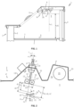
- the heating means 9 can be placed inside the compartment 5 in proximity to the upper side 4 of the frame, as better illustrated in Figure 1 and Figure 2 .
- the purpose of said means 9 is to promote the heating of the supporting plane 7 to a predetermined temperature T 1 .
- the heating means 9 are suited to transfer thermal energy (or heat) to the external surface 8 of the supporting plane 7 on which the food products P to be cooked/heated are directly placed.
- the thermal energy absorbed by the external surface 8 of the supporting plane 7 is transferred to the food products P by conduction, so as to cook/heat them.
- the heating means 9 may comprise at least one infrared source 10.
- a single infrared source 10 is used, which consists of one pair of rectilinear radiant tubes 11 mutually arranged side by side.
- These tubes 11 substantially extend along the entire length of the compartment 5.
- the configuration of the infrared source 10 is clearly visible in Figure 6 , where the radiant tubes 11 are anchored to an installation side 4' positioned in proximity to the upper side 4 by means of a plurality of shaped supports 12 arranged in a spaced manner along the extension of said tubes 11.
- the radiant tubes 11 are suited to be powered electrically (through appropriate electrical connections known per se and not illustrated in the Figures), in such a way as to generate an electromagnetic radiation in the infrared band.
- the radiant tubes may comprise a laminar parabolic element (generally made of a metallic material) positioned on their upper portion thereof so as to strongly limit infrared radiation in the area above the source 10. Furthermore, this parabolic element allows most of the infrared radiation that originally propagates upwards to be conveyed downwards and in the direction of the supporting plane 7.
- a laminar parabolic element generally made of a metallic material
- the parabolic element (not shown in the Figures) associated with the radiant tubes can be inserted inside the latter or, alternatively, it can be positioned externally and cover their upper outer surface, or both.
- the total electric power absorbed by an infrared source 10 installed in a cabinet according to this description can be included between 500W and 4000W.
- the infrared radiation emitted by the source 10 is almost completely absorbed by the upper surface 8 of the supporting plane 7, which causes the latter to heat up.
- the infrared source 10 can be anchored to the frame of the cabinet so as to follow a predetermined direction of installation, indicated by the reference letter X in the Figures.
- the infrared source is anchored to the frame of the cabinet so that it is arranged along the direction of installation X.
- the direction of installation X associated with the infrared source 10 can be tilted by a first predetermined inclination angle ⁇ with respect to the longitudinal development direction L of the frame 2.
- the first inclination angle ⁇ can be between 5° and 15° and can preferably range between 7° and 12°.
- the installation side 4' of the frame 2 can be bent and shaped in such a way as to feature three contiguous sections 13, 14, 15, each of which is flat and inclined.
- the supports 12 of the infrared source 10 can be anchored to the intermediate tilted section, indicated by the reference number 14 in the Figures.
- This intermediate section 14 is typically inclined by the first inclination angle ⁇ (generally included between 5° and 15°) with respect to the longitudinal axis L.
- the installation side 4' of the frame 2 has also one pair of flat and inclined sections 12, 15 arranged opposite and contiguous with the intermediate inclined section 14 to which the supports 12 of the infrared source 10 are anchored.
- Said inclined sections 12, 15 are arranged laterally to the source and are oriented in such a way that they converge towards a point located outside the compartment 5 (and outside the installation side 4' ).
- the first of these sections is tilted by a second predetermined inclination angle ⁇ with respect to the longitudinal axis L.
- the second angle of inclination ⁇ can be included between 40° and 60° and typically close to 50°.
- the other section of this pair is tilted by a third predetermined inclination angle ⁇ with respect to the longitudinal axis L.
- the third angle of inclination ⁇ can be included between 15° and 35° and typically close to 15°.
- Sections 13, 15 of the installation side 4 are arranged in such a way that they mutually converge towards a point K located outside the compartment 5, as clearly visible in Figure 2 .
- the cabinet 1 that is the subject of the present invention comprises a reflector element 16 positioned inside the compartment 5, under the infrared source 10.
- the reflector element 16 is inserted under the infrared source 10 in the space separating the radiant tubes 11, 11' and the upper surface 8 of supporting plane 7.
- the reflector element is installed under the infrared source 10 along a directrix J connecting the source 10 itself to a point Q of the supporting plane.
- This directrix is substantially constituted by a section of a straight line suited to directly connect the source 10 to a predetermined point Q on the upper surface 8 of the supporting plane 7.
- the reflector is arranged inside the compartment, in the space separating the infrared source 10 from the supporting plane 7, and in particular in the space visible to a hypothetical operator who looks downwards, that is, in the direction of the supporting plane 7, starting from a cross section of the cabinet made at the infrared source 10.
- the reflector element 16 is interposed in the path along which the infrared radiation would propagate between a starting point defined by the source 10 and an arrival point located in the upper surface 8 of the supporting plane 7; this radiation path, furthermore, is of the direct type, that is, it is constituted by a straight line during the propagation of which the electromagnetic radiation is not (or would not be) reflected by other objects present inside the compartment.
- the reflector element 16 therefore, is configured to at least partially reflect the infrared radiation generated by the source 10 towards the sides 3 and/or the installation side 4' of the frame 2.
- the reflector 16 is configured to reflect a part of the infrared radiation generated by the source 10 and suited to propagate inside the compartment 5 along a propagation direction that is such as to directly hit the supporting plane 7 (and the food product placed on it), that is, without being first reflected by other sides or objects located inside the compartment 5 or above the source 10.
- the reflector 16 is configured to reflect only a portion of the infrared radiation emitted by the source 10 and suited to reach the supporting plane 7 in a direct manner (that is, the radiation that hits the upper surface 8 of the supporting plane 7 without undergoing one or more reflections by the sides or objects located inside the compartment 5 ). The remaining part of the direct radiation emitted by the source 10 reaches the upper surface 8 of the supporting plane 7 (or the food product P placed on said supporting plane 7 ) without being reflected along its path.
- the width w 1 of the reflector 16 is considerably smaller than the transversal dimension w 2 of the compartment 5 just below the reflector 16 itself. In this way, therefore, a large part of the infrared radiation emitted by the source 10 will reach the plane supporting plane 7 (and the food product supported by it) directly and without interfering with the reflector 16, while a small part of the radiation emitted by the source 10 (and which would directly hit the supporting plane) is reflected by the reflector towards the sides 3 and/or the installation side 4' of the frame 2.
- the reflector element 16 will be suited to reflect most of the infrared radiation incident on it towards the installation side 4' of the frame 2.
- the shape of the reflector element 16 will be selected in such a way as to promote the reflection of most of the incident infrared radiation (generated by the source 10 ) towards the pair of inclined sections 13, 15 arranged beside the section 14 that supports the source 10 itself.
- the main function of the reflector element 16 is to "shield" a large area of the upper surface 8 of the supporting plane 7 from the direct infrared radiation generated by the source 10.
- the infrared radiation that reaches the reflector element 16 then hits the supporting plane 7 only after being reflected at least twice: i) a first time at the reflector element 16 itself, and ii) a second time at the installation side 4' of the frame 2 (or at the inclined sections 13, 15 comprising said side).
- the infrared radiation that reaches the reflector element 16 can then hit the supporting plane 7 after being further reflected following reflection i) and ii) mentioned above.
- the reflector element 16 is positioned at a relatively high distance d 3 from the supporting plane 7 and such as to prevent (or make substantially null) the transfer of thermal energy from the reflector element 16 to the food product P placed on the upper surface 8 of the supporting plane 7.
- the food product P located inside the compartment 5 can be heated exclusively through the infrared radiation emitted by the source 10 while the action of the reflector 16 in the process designed to heat/cook the food product P is almost zero.
- Figure 3 schematically shows the main paths followed by the infrared radiation that propagates from the source 10 to the supporting plane 7.
- two direct radiation beams invest the supporting plane 7 in proximity to its end portions 17.
- the expression "direct radiation beams” means the infrared radiation that is never reflected along the path connecting the source 10 to the supporting plane 7.
- the central portion 19 of the supporting plane 7, on the contrary, is hit by reflected infrared radiation; in particular, the beams that reach the central area of the supporting plane undergoes a first reflection at the reflector element 16 located under the source 10, and then are reflected a second time at the pair of inclined sections 13, 15 of the installation side 4'.
- the value of the second inclination angle ⁇ and of the third of inclination angle ⁇ respectively associated with the inclined sections 13, 15 of the upper side 4 are selected in such a way as to direct the incident infrared component (which has already been reflected at the reflector element 16 ) towards the supporting plane 7.
- the radiation beams shown in Figure 3 are to be considered as an example and are intended to indicate the two main types of radiation that hit the supporting plane 7. It should be noted, in fact, that a considerable part of the thermal energy associated with the latter is obtained through the combined effect (or overlapping) of the direct radiation coming from the source 10 and the radiation that has been reflected at the sides 3 of the frame 2 or other parts of the side 4'.
- the reflector element 16 can be constituted by a shaped metallic element extending over the full length of the infrared source 10.
- the reflector element 16 can consist of a metal section bar shaped so as to define a lowered central portion 21 and one pair of end portions 22 extending from opposite sides with respect to the central portion 21.
- this element has a substantially V-shaped cross section oriented so as to maintain the central portion 21 at a distance d 1 from the infrared source 10 greater than the distance d 2 , d 2 ' that separates the end portions 22 from the same source.
- the reflector element 16 is positioned so that the cusp (or vertex) of the "V" shape of the cross section is directed towards the supporting plane 7.
- the reflector element 16 can have a shape different from that shown in the Figures, however, the preferred shape and installation of this component require that its central position 21 be placed at a greater distance d 1 from the infrared source 10 than the distance d 2 at which the end portions 22 are placed.
- the reflector element has a substantially concave shape so as to direct the reflected radiation towards the installation side 4' of the frame 2, and in particular towards the inclined sections 13, 15 of the latter.
- the reflector element 16 is located under the infrared source 10 in a misaligned position (that is, not coaxial) with respect to the installation direction X of the latter.
- misaligned position in the preceding paragraph is intended to refer to the fact that the center plane of the reflector element, indicated by the symbol ⁇ in Figure 2 , is neither aligned with nor superimposed on the installation direction X of the infrared source 10; on the contrary, said plane ⁇ is spaced from the installation direction X by a predetermined distance d 3 .
- the center plane ⁇ of the reflector element 16 lies at its central portion 21, therefore it is evident that this portion 21 and the installation direction X are separated by the misalignment distance d 3 introduced above.
- the misalignment of the reflector element 16 with respect to the installation direction X makes it possible to vary the amount of infrared radiation emitted by the source 10 that reaches the supporting plane 7 directly, that is, without being reflected during its propagation.
- the central portion 21 of the reflector element 16 (or, alternatively, its center plane ⁇ ) is offset to the right by the misalignment distance d 3 with respect to the installation direction X of the source 10.
- the misalignment of the reflector element with respect to the installation axis of the source generates an asymmetrical reflection with respect to the infrared radiation emitted by the tubes 11', 11".
- the size of the infrared source 10 affects the size and position of the reflector element inside the compartment 5.
- the dimensional relationship between the distances/dimensions of the reflector element 16 and the width W of the infrared source can be expressed as follows:
- the values of the distances/dimensions of the reflector element 16 are as follows:
- the arrangement of a reflector element 16 in accordance with the distances/dimensions specified above makes it possible to considerably reduce the temperature gradient ⁇ T present on the external surface 8 of the supporting plane 8.
- the installation of one reflector element 16 of the type described above in the compartment 5 can promote a more uniform distribution of temperature on the upper surface 8 of the supporting plane 7; for example, the temperature gradient ⁇ T (that is, the thermal differential between two points of said surface) may be less than 10% and typically close to 5%.
- the installation side 4' of the frame 2 can have an additional shaped section 23 placed beside the infrared source 10 and suited to define a housing 24 for one or more LED lamps 25.
- the LED lamps 25 can be distributed along the transverse extension of the installation side 4'.
- LED lamps 25 are illustrated schematically in Figure 2 .
- the function of the LED lamps 25 is to illuminate the food products placed on the supporting plane 7.
- the cabinet 1 can include also a cooling system 26 suited to maintain the temperature near the infrared source 10 and the LED lamps 25 within a predetermined range of values below the maximum permissible values for said components.
- the cooling system 26 can comprise a metallic supporting element 27, illustrated in Figure 5 , intended to be positioned above the installation side 4' suited to support the infrared lamp 10 and the LED lamps 25.
- This metallic element 27 is suited to support a plurality of fans 28 preferably positioned side by side along the transverse extension direction of the support itself.
- the metallic element 27 can be provided with a plurality of openings 29 located at the fans 28.
- the installation side 4' is provided with a plurality of slits 30 arranged in such a way as to form rows (or lines) that extend over the entire transverse extension the side itself.
- the slits 30 are visible in Figure 6 .
- the presence of the slits 30 and the openings 29 makes it possible to promote the circulation of an air flow that hits the infrared source 10 and is suited to extract the heat generated by the latter and by the LED lamps 25 and distribute it inside the compartment 5.
- the activation of the fans 28 promotes the generation of a fresh air flow, the circulation of which is forced through the opening 29.
- This flow is subsequently conveyed towards the slits 30 in such a way as to generate a downward blow at the outlet of the the slits 30.
- This blowing action helps to dissipate the heat that formed in the upper area of the compartment 5 by conveying it towards the lower area of the compartment itself.
- Blowing air downwards helps to promote the heating of the food products P placed on the supporting plane 7, as well as to prevent the sides of the compartment from fogging up.
- a first set of slits 30 can be configured to generate an air flow directed downwards and suited to hit the LED lamps 25 and the infrared source 10 in order to cool them.
- a second set of slits 30 can be configured to generate the circulation of a substantially laminar air flow that skims the installation side 4' and possibly also with the upper side 4 of the compartment 5.
- This laminar air flow helps to maintain the temperature of the installation side 4' at values that are not dangerous in case of contact with a user's body.
- the circulation of air within the compartment 5 thus makes it possible to cool the infrared source 10 and the LED lamps 25 and prevent them from overheating, which could damage them or reduce their service life.
- the circulation of the air flow makes it possible to keep all the components located inside the compartment 5 at a temperature lower than a critical value, in such a way as to reduce the risk of burns for a user who comes into contact with one or more of said components.
- the heat produced by the infrared source 10 and the LED lamps 25 is also used to heat the food products P positioned on the supporting plane 7; thanks to this feature, it is possible to increase the thermal efficiency of the cabinet 1 and reduce the energy consumption associated with the latter.
- the special configuration of the cooling system 26 makes it possible to generate hot air flows oriented towards the supporting plane 7 and suited to contribute to the heating/cooking of the food products P placed inside the compartment.
- This special configuration of the cooling system 26 makes it possible to reuse for heating/cooking purposes of the food products P a good portion of the amount of heat generated by the source and the lamps; until now this heat has been considered a "side effect" associated with the operation of the radiant/luminous devices and therefore completely useless for the efficiency of the cabinet.
- the circulation of the air flow prevents condensation on the sides 3 (generally made of glass) that delimit the compartment 5, keeping them always clear and substantially clean.
- the heating means 9 can include an electromagnetic induction heat source (not shown in the Figures) suited to promote the heating of the supporting element.
- the heating of the supporting plane can be achieved through the synergetic effect obtained mainly by combining two distinct heat sources: an infrared source 10 and an electromagnetic induction source.
Landscapes
- Engineering & Computer Science (AREA)
- Food Science & Technology (AREA)
- Electric Stoves And Ranges (AREA)
- Freezers Or Refrigerated Showcases (AREA)
Claims (14)
- Schrank zum Präsentieren und Konservieren von gekochten, erhitzten
Lebensmittelprodukten (P), umfassend:- einen Tragrahmen (2), der mit einer Vielzahl von Seiten (3, 4) versehen ist, die dazu geeignet sind, ein Innenfach (5) zu definieren;- eine Tragebene (7) mit einer oberen Oberfläche (8), die innerhalb des besagten Fachs (5) positioniert ist und dazu geeignet ist, die gekochten Lebensmittelprodukte (P), die präsentiert und konserviert werden sollen, zu tragen;- Heizmittel (9), die innerhalb des besagten Fachs (5) über der besagten flachen Tragebene (7) positioniert sind, wobei die besagten Heizmittel (9) dazu geeignet sind, die besagte flache Tragebene (7) auf eine vorbestimmte Temperatur (T) zu erhitzen;wobei die besagten Heizmittel (9) mindestens eine Infrarotquelle (10) umfassen;wobei er ein Reflektorelement (16) umfasst, das innerhalb des besagten Fachs (5) positioniert und unter der besagten Infrarotquelle (10) angeordnet ist, wobei das besagte Reflektorelement (16) dazu geeignet ist, die Infrarotstrahlung, die von der besagten Infrarotquelle (10) emittiert wird, zumindest teilweise zu reflektieren;der besagte Reflektor (16) so konfiguriert ist, dass er nur einen Teil der Infrarotstrahlung, die von der besagten Quelle (10) emittiert wird, reflektiert und dazu geeignet ist, die besagte Tragebene (7) direkt zu erreichen;
derart, um einen großen Bereich der besagten oberen Oberfläche (8) der besagten Tragebene (7) vor der direkten Infrarotstrahlung, die von der besagten Quelle (10) erzeugt wird, abzuschirmen, wobei der verbleibende Teil der direkten Strahlung, die von der Quelle (10) emittiert wird, die obere Oberfläche (8) des Lebensmittelprodukts (P) erreicht, ohne auf seinem Weg reflektiert zu werden. - Schrank nach Patentanspruch 1, dadurch gekennzeichnet, dass der besagte Tragrahmen (2) eine Längsachse (L) definiert und die besagte Infrarotquelle (10) eine vorbestimmte Installationsrichtung (X) aufweist, wobei die besagte Quelle (10) an einer Installationsseite (4') verankert ist, die in der Nähe der Oberseite (4) des besagten Tragrahmens (2) platziert ist, wobei die besagte Installationsrichtung (X) in Bezug auf die besagte Längsachse (L) um einen ersten vorbestimmten Neigungswinkel (α) geneigt ist.
- Schrank nach Patentanspruch 2, dadurch gekennzeichnet, dass der besagte erste Neigungswinkel (α) zwischen 7° und 12° liegt.
- Schrank nach einem oder mehreren der vorhergehenden Patentansprüche, dadurch gekennzeichnet, dass der Querschnitt des besagten Reflektorelements (16) eine vorbestimmte Form aufweist, die einen zentralen Abschnitt (21) und ein Paar Endabschnitte (22), die sich von gegenüberliegenden Seiten in Bezug auf den besagten zentralen Abschnitt (21) erstrecken, definiert.
- Schrank nach Patentanspruch 3, dadurch gekennzeichnet, dass der besagte zentrale Abschnitt (21) in einem ersten Abstand (d1 ) von der besagten Infrarotquelle (10) positioniert ist und die besagten Endabschnitte (22) in einem zweiten Abstand (d2, d2') von der besagten Infrarotquelle (10) positioniert sind, wobei die besagten Abstände (d1 , d2, d2') entlang der Installationsrichtung (X) der besagten Infrarotquelle (10) bestimmt werden.
- Schrank nach Patentanspruch 5, dadurch gekennzeichnet, dass der besagte erste Abstand (d1 ) größer ist als der besagte zweite Abstand (d2, d2').
- Schrank nach einem oder mehreren der vorhergehenden Patentansprüche, dadurch gekennzeichnet, dass die besagte Infrarotquelle (10) und das besagte Reflektorelement (12) jeweils vorbestimmte Breiten (w, w1 ) aufweisen; die Breite (w1 ) des besagten Reflektorelements (16) in einem Bereich liegt, der durch einen Mindestwert (w1_min ), der fünf Zehnteln der Breite (w) der besagten Infrarotquelle (10) entspricht, und einen Höchstwert (w1_max ), der der Breite (w) der besagten Infrarotquelle (10) entspricht, definiert ist.
- Schrank nach Patentanspruch 7, dadurch gekennzeichnet, dass der Abstand (d1 ) des besagten zentralen Abschnitts (21) von der besagten Infrarotquelle (10) in einem Bereich liegt, der durch einen Mindestwert (d1_min ), der der Breite (w) der Infrarotquelle (10) entspricht, und einen Höchstwert (d1_max ), der dem Doppelten der Breite (w) der besagten Infrarotquelle (10) entspricht, definiert ist.
- Schrank nach einem oder mehreren der vorhergehenden Patentansprüche, dadurch gekennzeichnet, dass die Mittellinie des besagten zentralen Abschnitts (21) des besagten Reflektorelements (16) in Bezug auf die Installationsrichtung (X) der besagten Infrarotquelle (10) fehlausgerichtet ist.
- Schrank nach Patentanspruch 9, dadurch gekennzeichnet, dass der Wert der Fehlausrichtung (d3 ) des besagten zentralen Abschnitts (21) in Bezug auf die besagte Installationsrichtung (X) in einem Bereich liegt, der durch einen Mindestwert (d3_min ), der einem Zehntel der Breite (w) der besagten Infrarotquelle (10) entspricht, und einen Höchstwert (d3_max ), der fünf Zehnteln der Breite (w) der besagten Infrarotquelle (10) entspricht, definiert ist.
- Schrank nach einem oder mehreren der vorhergehenden Patentansprüche, dadurch gekennzeichnet, dass die Installationsseite (4') zwei geneigte Abschnitte (13, 15) aufweist, die seitlich zur besagten Infrarotquelle (10) angeordnet sind, wobei die besagten geneigten Abschnitte (13, 15) in Bezug auf einen Punkt (K) außerhalb des besagten Fachs (5) zueinander konvergent sind.
- Schrank nach Patentanspruch 11, dadurch gekennzeichnet, dass einer der besagten geneigten Abschnitte (13) in Bezug auf die besagte Längsachse (L) einen zweiten Neigungswinkel (β) aufweist, der zwischen 35° und 60° liegt, und der andere geneigte Abschnitt (15) in Bezug auf die besagte Längsachse (L) einen dritten Neigungswinkel (γ) aufweist, der zwischen 15° und 40° liegt.
- Schrank nach Patentanspruch 1, dadurch gekennzeichnet, dass die besagten Heizmittel (9) eine magnetische Induktionsquelle umfassen, die unter der besagten Tragebene positioniert ist.
- Schrank nach Patentanspruch 1, dadurch gekennzeichnet, dass die besagte Tragebene (7) aus einem Material besteht, das aus der Gruppe von Materialien ausgewählt ist, die dazu geeignet sind, die Infrarotstrahlung, die von der besagten Infrarotquelle (10) emittiert wird, zu absorbieren.
Applications Claiming Priority (1)
| Application Number | Priority Date | Filing Date | Title |
|---|---|---|---|
| IT102021000020666A IT202100020666A1 (it) | 2021-07-30 | 2021-07-30 | Armadio per l’esposizione e la conservazione di prodotti alimentari cotti |
Publications (3)
| Publication Number | Publication Date |
|---|---|
| EP4124265A1 EP4124265A1 (de) | 2023-02-01 |
| EP4124265B1 true EP4124265B1 (de) | 2024-10-23 |
| EP4124265C0 EP4124265C0 (de) | 2024-10-23 |
Family
ID=78463702
Family Applications (1)
| Application Number | Title | Priority Date | Filing Date |
|---|---|---|---|
| EP22187974.5A Active EP4124265B1 (de) | 2021-07-30 | 2022-07-29 | Schaukasten für die ausstellung und lagerung von gekochten lebensmitteln |
Country Status (2)
| Country | Link |
|---|---|
| EP (1) | EP4124265B1 (de) |
| IT (1) | IT202100020666A1 (de) |
Family Cites Families (4)
| Publication number | Priority date | Publication date | Assignee | Title |
|---|---|---|---|---|
| JP2951110B2 (ja) * | 1992-07-01 | 1999-09-20 | 三洋電機株式会社 | ショーケース |
| GB2349454A (en) * | 1999-03-26 | 2000-11-01 | Counterline Limited | Radiant heater for food display unit with infrared source and emitter plate |
| KR20040071016A (ko) * | 2003-02-06 | 2004-08-11 | 삼성전자주식회사 | 조리장치 |
| US8076614B2 (en) * | 2006-09-01 | 2011-12-13 | Nieco Corporation | Multi-stage cooking system using radiant, convection, and magnetic induction heating, and having a compressed air heat guide |
-
2021
- 2021-07-30 IT IT102021000020666A patent/IT202100020666A1/it unknown
-
2022
- 2022-07-29 EP EP22187974.5A patent/EP4124265B1/de active Active
Also Published As
| Publication number | Publication date |
|---|---|
| EP4124265A1 (de) | 2023-02-01 |
| IT202100020666A1 (it) | 2023-01-30 |
| EP4124265C0 (de) | 2024-10-23 |
Similar Documents
| Publication | Publication Date | Title |
|---|---|---|
| US11242998B2 (en) | Radiation grill | |
| AU2008361596B2 (en) | Smokeless barbecue | |
| US11464362B2 (en) | Radiation grill | |
| US6031208A (en) | Topless holding bin with side heat source | |
| US8522675B2 (en) | Holding cabinet for separately heating food trays | |
| US3632968A (en) | Self-service food warmer assembly | |
| EP3376116B1 (de) | Kochgerät mit einer beleuchtungsvorrichtung | |
| US12042091B2 (en) | Electric roasting machine | |
| EP4124265B1 (de) | Schaukasten für die ausstellung und lagerung von gekochten lebensmitteln | |
| US9803875B2 (en) | Electric oven with a heating element reflector | |
| ES2877225T3 (es) | Armario con cortinas de aire opuestas | |
| US7423241B2 (en) | Heating element for oven | |
| US20140265756A1 (en) | Door for a refrigerated merchandiser | |
| CN1979000A (zh) | 热风对流加热装置的微波炉 | |
| JP5595174B2 (ja) | 加熱調理器 | |
| US8487224B2 (en) | Microwave oven | |
| US3546427A (en) | Combination foodwarmer and light | |
| US7677240B2 (en) | Food oven | |
| IT202000002890A1 (it) | Espositore di cibi riscaldati. | |
| KR20010096949A (ko) | 전자렌지용 반사판의 광집중구조 | |
| NZ584623A (en) | An open faced article storage unit with multiple temperature adjustable shelves | |
| ITRE20090020A1 (it) | Modulo di riscaldamento a raggi infrarossi per apparechiature di riscaldamento, cottura e grigliatura cibi ed alimenti in genere. | |
| JPS6277585A (ja) | シヨ−ケ−ス |
Legal Events
| Date | Code | Title | Description |
|---|---|---|---|
| PUAI | Public reference made under article 153(3) epc to a published international application that has entered the european phase |
Free format text: ORIGINAL CODE: 0009012 |
|
| STAA | Information on the status of an ep patent application or granted ep patent |
Free format text: STATUS: THE APPLICATION HAS BEEN PUBLISHED |
|
| AK | Designated contracting states |
Kind code of ref document: A1 Designated state(s): AL AT BE BG CH CY CZ DE DK EE ES FI FR GB GR HR HU IE IS IT LI LT LU LV MC MK MT NL NO PL PT RO RS SE SI SK SM TR |
|
| P01 | Opt-out of the competence of the unified patent court (upc) registered |
Effective date: 20230531 |
|
| STAA | Information on the status of an ep patent application or granted ep patent |
Free format text: STATUS: REQUEST FOR EXAMINATION WAS MADE |
|
| 17P | Request for examination filed |
Effective date: 20230731 |
|
| RBV | Designated contracting states (corrected) |
Designated state(s): AL AT BE BG CH CY CZ DE DK EE ES FI FR GB GR HR HU IE IS IT LI LT LU LV MC MK MT NL NO PL PT RO RS SE SI SK SM TR |
|
| GRAP | Despatch of communication of intention to grant a patent |
Free format text: ORIGINAL CODE: EPIDOSNIGR1 |
|
| STAA | Information on the status of an ep patent application or granted ep patent |
Free format text: STATUS: GRANT OF PATENT IS INTENDED |
|
| INTG | Intention to grant announced |
Effective date: 20240531 |
|
| GRAS | Grant fee paid |
Free format text: ORIGINAL CODE: EPIDOSNIGR3 |
|
| GRAA | (expected) grant |
Free format text: ORIGINAL CODE: 0009210 |
|
| STAA | Information on the status of an ep patent application or granted ep patent |
Free format text: STATUS: THE PATENT HAS BEEN GRANTED |
|
| AK | Designated contracting states |
Kind code of ref document: B1 Designated state(s): AL AT BE BG CH CY CZ DE DK EE ES FI FR GB GR HR HU IE IS IT LI LT LU LV MC MK MT NL NO PL PT RO RS SE SI SK SM TR |
|
| REG | Reference to a national code |
Ref country code: GB Ref legal event code: FG4D |
|
| REG | Reference to a national code |
Ref country code: CH Ref legal event code: EP |
|
| REG | Reference to a national code |
Ref country code: DE Ref legal event code: R096 Ref document number: 602022007010 Country of ref document: DE |
|
| REG | Reference to a national code |
Ref country code: IE Ref legal event code: FG4D |
|
| U01 | Request for unitary effect filed |
Effective date: 20241121 |
|
| U07 | Unitary effect registered |
Designated state(s): AT BE BG DE DK EE FI FR IT LT LU LV MT NL PT RO SE SI Effective date: 20241202 |
|
| P04 | Withdrawal of opt-out of the competence of the unified patent court (upc) registered |
Free format text: CASE NUMBER: APP_63218/2024 Effective date: 20241128 |
|
| PG25 | Lapsed in a contracting state [announced via postgrant information from national office to epo] |
Ref country code: HR Free format text: LAPSE BECAUSE OF FAILURE TO SUBMIT A TRANSLATION OF THE DESCRIPTION OR TO PAY THE FEE WITHIN THE PRESCRIBED TIME-LIMIT Effective date: 20241023 Ref country code: IS Free format text: LAPSE BECAUSE OF FAILURE TO SUBMIT A TRANSLATION OF THE DESCRIPTION OR TO PAY THE FEE WITHIN THE PRESCRIBED TIME-LIMIT Effective date: 20250223 |
|
| PG25 | Lapsed in a contracting state [announced via postgrant information from national office to epo] |
Ref country code: ES Free format text: LAPSE BECAUSE OF FAILURE TO SUBMIT A TRANSLATION OF THE DESCRIPTION OR TO PAY THE FEE WITHIN THE PRESCRIBED TIME-LIMIT Effective date: 20241023 |
|
| PG25 | Lapsed in a contracting state [announced via postgrant information from national office to epo] |
Ref country code: NO Free format text: LAPSE BECAUSE OF FAILURE TO SUBMIT A TRANSLATION OF THE DESCRIPTION OR TO PAY THE FEE WITHIN THE PRESCRIBED TIME-LIMIT Effective date: 20250123 |
|
| PG25 | Lapsed in a contracting state [announced via postgrant information from national office to epo] |
Ref country code: GR Free format text: LAPSE BECAUSE OF FAILURE TO SUBMIT A TRANSLATION OF THE DESCRIPTION OR TO PAY THE FEE WITHIN THE PRESCRIBED TIME-LIMIT Effective date: 20250124 |
|
| PG25 | Lapsed in a contracting state [announced via postgrant information from national office to epo] |
Ref country code: PL Free format text: LAPSE BECAUSE OF FAILURE TO SUBMIT A TRANSLATION OF THE DESCRIPTION OR TO PAY THE FEE WITHIN THE PRESCRIBED TIME-LIMIT Effective date: 20241023 |
|
| PG25 | Lapsed in a contracting state [announced via postgrant information from national office to epo] |
Ref country code: RS Free format text: LAPSE BECAUSE OF FAILURE TO SUBMIT A TRANSLATION OF THE DESCRIPTION OR TO PAY THE FEE WITHIN THE PRESCRIBED TIME-LIMIT Effective date: 20250123 |
|
| U20 | Renewal fee for the european patent with unitary effect paid |
Year of fee payment: 4 Effective date: 20250527 |
|
| PG25 | Lapsed in a contracting state [announced via postgrant information from national office to epo] |
Ref country code: SM Free format text: LAPSE BECAUSE OF FAILURE TO SUBMIT A TRANSLATION OF THE DESCRIPTION OR TO PAY THE FEE WITHIN THE PRESCRIBED TIME-LIMIT Effective date: 20241023 |
|
| PG25 | Lapsed in a contracting state [announced via postgrant information from national office to epo] |
Ref country code: SK Free format text: LAPSE BECAUSE OF FAILURE TO SUBMIT A TRANSLATION OF THE DESCRIPTION OR TO PAY THE FEE WITHIN THE PRESCRIBED TIME-LIMIT Effective date: 20241023 |
|
| PG25 | Lapsed in a contracting state [announced via postgrant information from national office to epo] |
Ref country code: CZ Free format text: LAPSE BECAUSE OF FAILURE TO SUBMIT A TRANSLATION OF THE DESCRIPTION OR TO PAY THE FEE WITHIN THE PRESCRIBED TIME-LIMIT Effective date: 20241023 |
|
| PLBE | No opposition filed within time limit |
Free format text: ORIGINAL CODE: 0009261 |
|
| STAA | Information on the status of an ep patent application or granted ep patent |
Free format text: STATUS: NO OPPOSITION FILED WITHIN TIME LIMIT |
|
| 26N | No opposition filed |
Effective date: 20250724 |