US8076614B2 - Multi-stage cooking system using radiant, convection, and magnetic induction heating, and having a compressed air heat guide - Google Patents
Multi-stage cooking system using radiant, convection, and magnetic induction heating, and having a compressed air heat guide Download PDFInfo
- Publication number
- US8076614B2 US8076614B2 US12/410,284 US41028409A US8076614B2 US 8076614 B2 US8076614 B2 US 8076614B2 US 41028409 A US41028409 A US 41028409A US 8076614 B2 US8076614 B2 US 8076614B2
- Authority
- US
- United States
- Prior art keywords
- cooking
- food product
- magnetic induction
- heating
- cooking chamber
- Prior art date
- Legal status (The legal status is an assumption and is not a legal conclusion. Google has not performed a legal analysis and makes no representation as to the accuracy of the status listed.)
- Expired - Fee Related, expires
Links
- 238000010411 cooking Methods 0.000 title claims abstract description 91
- 238000010438 heat treatment Methods 0.000 title claims abstract description 62
- 230000006698 induction Effects 0.000 title claims abstract description 39
- 235000013305 food Nutrition 0.000 claims abstract description 58
- 238000000034 method Methods 0.000 claims description 6
- 230000008569 process Effects 0.000 claims description 4
- 238000007599 discharging Methods 0.000 claims description 2
- 238000002347 injection Methods 0.000 claims 1
- 239000007924 injection Substances 0.000 claims 1
- 241000287828 Gallus gallus Species 0.000 description 15
- 235000013550 pizza Nutrition 0.000 description 10
- 239000000463 material Substances 0.000 description 7
- 230000003197 catalytic effect Effects 0.000 description 5
- 235000015220 hamburgers Nutrition 0.000 description 5
- 230000001681 protective effect Effects 0.000 description 5
- 239000000919 ceramic Substances 0.000 description 3
- 238000005485 electric heating Methods 0.000 description 3
- 235000013611 frozen food Nutrition 0.000 description 3
- 239000011521 glass Substances 0.000 description 3
- 230000005855 radiation Effects 0.000 description 3
- XLYOFNOQVPJJNP-UHFFFAOYSA-N water Chemical compound O XLYOFNOQVPJJNP-UHFFFAOYSA-N 0.000 description 3
- 230000004888 barrier function Effects 0.000 description 2
- 230000008901 benefit Effects 0.000 description 2
- 238000004891 communication Methods 0.000 description 2
- 238000010276 construction Methods 0.000 description 2
- 230000000694 effects Effects 0.000 description 2
- 235000013410 fast food Nutrition 0.000 description 2
- 239000012530 fluid Substances 0.000 description 2
- 238000004519 manufacturing process Methods 0.000 description 2
- 238000011160 research Methods 0.000 description 2
- 241000251468 Actinopterygii Species 0.000 description 1
- 241000833020 Padilla Species 0.000 description 1
- 239000004809 Teflon Substances 0.000 description 1
- 229920006362 Teflon® Polymers 0.000 description 1
- 238000003491 array Methods 0.000 description 1
- 235000013330 chicken meat Nutrition 0.000 description 1
- 238000004140 cleaning Methods 0.000 description 1
- 230000003750 conditioning effect Effects 0.000 description 1
- 238000011161 development Methods 0.000 description 1
- 239000011152 fibreglass Substances 0.000 description 1
- 235000019688 fish Nutrition 0.000 description 1
- 239000011888 foil Substances 0.000 description 1
- 239000000446 fuel Substances 0.000 description 1
- 239000004519 grease Substances 0.000 description 1
- 235000019692 hotdogs Nutrition 0.000 description 1
- 238000003780 insertion Methods 0.000 description 1
- 230000037431 insertion Effects 0.000 description 1
- 239000002184 metal Substances 0.000 description 1
- 238000012986 modification Methods 0.000 description 1
- 230000004048 modification Effects 0.000 description 1
- 238000002360 preparation method Methods 0.000 description 1
- 244000038651 primary producers Species 0.000 description 1
- 230000000284 resting effect Effects 0.000 description 1
- 235000013580 sausages Nutrition 0.000 description 1
- 239000000779 smoke Substances 0.000 description 1
- 229910001220 stainless steel Inorganic materials 0.000 description 1
- 239000010935 stainless steel Substances 0.000 description 1
Images


Classifications
-
- A—HUMAN NECESSITIES
- A47—FURNITURE; DOMESTIC ARTICLES OR APPLIANCES; COFFEE MILLS; SPICE MILLS; SUCTION CLEANERS IN GENERAL
- A47J—KITCHEN EQUIPMENT; COFFEE MILLS; SPICE MILLS; APPARATUS FOR MAKING BEVERAGES
- A47J37/00—Baking; Roasting; Grilling; Frying
- A47J37/04—Roasting apparatus with movably-mounted food supports or with movable heating implements; Spits
- A47J37/044—Roasting apparatus with movably-mounted food supports or with movable heating implements; Spits with conveyors moving in a horizontal or an inclined plane
-
- A—HUMAN NECESSITIES
- A23—FOODS OR FOODSTUFFS; TREATMENT THEREOF, NOT COVERED BY OTHER CLASSES
- A23L—FOODS, FOODSTUFFS, OR NON-ALCOHOLIC BEVERAGES, NOT COVERED BY SUBCLASSES A21D OR A23B-A23J; THEIR PREPARATION OR TREATMENT, e.g. COOKING, MODIFICATION OF NUTRITIVE QUALITIES, PHYSICAL TREATMENT; PRESERVATION OF FOODS OR FOODSTUFFS, IN GENERAL
- A23L3/00—Preservation of foods or foodstuffs, in general, e.g. pasteurising, sterilising, specially adapted for foods or foodstuffs
- A23L3/005—Preservation of foods or foodstuffs, in general, e.g. pasteurising, sterilising, specially adapted for foods or foodstuffs by heating using irradiation or electric treatment
Definitions
- the present invention relates generally to broiler systems for the rapid cooking of food products, and more particularly to a broiler system combining different kinds of heating methods and including a novel compressed air system and heating element combination which guides and directs heat onto food product in the cooking chamber.
- the system is adapted for cooking a variety of food products through the combination of magnetic induction, radiant, and convection heat.
- high output commercial food purveyors i.e., fast food restaurants
- cooking systems usually comprise a housing having a horizontal conveyor for moving food product from an input end to an output end.
- the systems typically comprise a housing having a horizontal conveyor for moving food product from an input end to an output end.
- the systems typically comprise a housing having a horizontal conveyor for moving food product from an input end to an output end.
- the systems typically comprise a housing having a horizontal conveyor for moving food product from an input end to an output end.
- the food passes between a number of spaced-apart cooking elements, typically either electric resistance elements or gas burners.
- the profitability of utilizing such a system hinges on a number of factors, including the rapidity and efficiency with which the food product can be cooked, the minimization of energy and/or fuel utilized in cooking, the ease with which the system can be serviced and cleaned, the quality (and therefore desirability) of the cooked food products, and so forth.
- the present invention improves on prior art broiler systems by providing a system which includes a combination of magnetic induction heating element, gas or electric heating elements, a compressed air system which distributes and directs forced air through an plenum disposed above the cooking food product into the cooking chamber, and heat reflecting surfaces (i.e., radiant heat/infrared heating elements) on both the underside of the air plenum and on other structures within the cooking chamber.
- the combination multi-stage cooking system provides rapidly cooked food products of uniform doneness, high quality, and moisture content.
- U.S. Pat. No. 4,936,286, to Baker discloses a broiler system having at least two side-by-side broiling conveyors, and broiler units mounted adjacent to the conveyors extending across the combined widths of the two conveyors.
- a broiler unit is provided with a shield which blocks off the heated face of the broiler unit where the broiler unit faces one of the conveyors.
- the shield preferably carries a portion which extends towards the adjacent edges of two conveyors to prevent lateral heat radiation between the conveyors.
- U.S. Pat. No. 4,188,868, to Baker et al shows a broiler system having a food passageway restricted by baffles, including an entrance shield of heat-reflecting material formed as a fitting over the entrance burner housing and including a baffle sheet extending from the entrance burner housing through most of the gap toward the entrance opening, and an exit shield of similar heat-reflecting material formed as a fitting over the exit burner housing and having a baffle sheet extending from the exit burner housing through most of the gap toward the exit opening.
- an intermediate shield including a horizontal sheet of similar material resting on adjacent burner housings and having a vertical sheet depending from said horizontal sheet. The entrance shield, the exit shield and the intermediate shield define the upper limits of the passageway through the burner and tend to reflect heat away from the entrance and exit openings and to limit air circulation within and through the passageway.
- U.S. Pat. No. 4,121,509 to Baker et al., teaches a housing having a passageway through which a continuous food conveyor operates, taking food products from an inlet end to an outlet end. Within the passageway the food products are exposed to infrared radiation from heaters, hot air blown from a fan through a supply duct and through groups of nozzles onto the patties, and steam or hot water vapor provided through the air supply.
- infrared radiation direct infrared radiation, warm air, and water vapor—the system provides a quickly cooked food product having a relatively high moisture content.
- U.S. Pat. No. 3,987,718 to Lang-Ree et al. discloses a hamburger patty and bun cooker having a frame supporting lower and upper heated platens.
- a product conveyor typical of such systems, moves food product from the inlet to the outlet.
- At least one of the platens is provided with a low-friction layer between it and an advancing patty.
- the layer is constituted by jets of hot air discharged over the platen surface or by a Teflon-coated thin, metal foil sheet or by a Teflon-carrying thin, fiber glass sheet, the sheets being readily changeable.
- Bun portions for the individual patties are advanced on the same frame in paths parallel to the hamburger patties by comparable endless conveyors and are heated by individual platens on the frame as the bun portions advance.
- U.S. Pat. No. 5,277,924 to Padilla teaches a conveyorized pizza cooking system that includes a radio frequency chamber located downstream of the pizza loading station for proofing pizza dough shells using RF energy in the radio frequency chamber on the conveyor. It does not include a magnetic induction plate.
- U.S. Pat. Appl. Ser. No. 2005/0256774 by Clothier et al teaches a food preparation system that conveys food during cooking and includes at least one heating station, which may include one or more induction cooktops.
- U.S. Pat. No. 6,915,734 to Torghele et al teaches an automated pizza production oven in which an automatically prepared pizza is baked in one of multiple ovens.
- One unit may be an induction unit, although such a unit is not shown in combination with other kinds of heating methods.
- U.S. Pat. No. 4,164,591 to Ahlgren et al disclose a pizza oven having a track for conveying pizzas through a cooking chamber with multiple oven types, including convection oven with radiant heat and a toasting zone.
- An intermediate section includes a baking zone which is not directly exposed to heating elements but where heating is by convection from the heater elements.
- the present invention is an improved combination multi-stage cooking system, which combines in novel fashion a magnetic induction heating stage with convection and radiant heating. Notable among the novel elements is the use of a magnetic induction heating stage physically incorporated into a cooking system in close proximity to a convection and radiant heating cooking chamber, but provided with shielding to prevent damage to the magnetic induction coils.
- the inventive system optionally includes a novel gas burner element with a novel radiant shroud having a wing configuration that directs and distributes gas flames so as to spread the heat provided by the elements and to include radiant heating surface on the underside of the wings.
- Yet another object of the present invention to provide a new and improved cooking system that utilizes forced air to direct and confine heat from heating elements in a cooking chamber to increase food heating efficiency.
- a further object or feature of the present invention is a new and improved cooking system that enhances the ability to produce a more uniform and aesthetically pleasing browning of rapidly cooked foods.
- FIG. 1 is a perspective view of the inventive multi-stage forced air cooking system, showing the system with the top cover removed and the upper catalytic converter partly cut away to reveal the upper gas burner array, this view not showing the magnetic induction heating stage included;
- FIG. 2 is a partial cross-sectional top plan view showing the burner array, upper catalytic unit, and air supply plenum of the system of FIG. 1 ;
- FIG. 3 is a cross-sectional side view in elevation of the upper portion of the broiler housing and heating system taken along the Section lines 3 - 3 shown in FIG. 2 ;
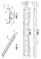
- FIG. 4 is a perspective view of the novel gas burner and radiant cap for the gas burners as employed in a preferred embodiment of the present inventive cooking system
- FIG. 5 is a top plan view of the gas burner of FIG. 4 ;
- FIG. 6 is side view in elevation of the gas burner of FIGS. 4 and 5 ;
- FIG. 7 is an end view in elevation of the gas burner and radiant cap
- FIG. 8 is a perspective view of the inventive cooking system as shown in FIGS. 1-7 , but further including a magnetic induction heating stage;
- FIG. 9 is a partial cross-sectional top plan view thereof.
- FIG. 10 is a cross-sectional side view in elevation thereof, as taken along section line 10 - 10 of FIG. 9 ;
- FIG. 11 is an upper front perspective view schematically showing how the magnetic induction plate is incorporated into the conveyor oven of the present invention.
- FIG. 12 is a partial cross sectional perspective view taken along section line 12 - 12 of FIG. 11 , showing the magnetic induction coils sandwiched in a ceramic glass enclosure for protection from radiant and convection heat;
- FIG. 12A shows an alternative configuration of magnetic induction coils that may be enclosed within the protective enclosure shown in FIGS. 11 and 12 .
- FIGS. 1 through 6 wherein like reference numerals refer to like components in the various views, there is illustrated therein a new and improved multi-product cooking system, generally denominated 100 herein.
- FIGS. 1-3 illustrate the general structural and operative elements of a first preferred embodiment of the cooking system of the present invention 100 , showing that the inventive apparatus includes: a support frame and carriage 110 ; a cooking chamber (or housing) 120 (preferably stainless steel); an automatic food product feeder 130 ; a cooking control panel 140 presenting a consolidated plurality of control dials, button, switches, and the like; an upper catalytic converter 150 ; and an upper gas burner array 160 .
- Food products such as pizza and hamburger patties 170 are conveyed into the inlet end 180 of the cooking chamber using the automatic product feeder, and via an inlet product conveyor 190 , the food product is passed on to a product conveyor belt or grid 200 , which moves the food product through the cooking chamber 210 and to the outlet end 220 of the housing.
- the cooking chamber includes a constellation of electric resistance heating elements and/or gas burners, each in spaced-apart arrays and disposed both above and below the product conveyor belt, as well as a plurality of reflective surfaces, all of which combine to provide both radiant and convective heat tailored to produce a continuous output of highly desirable food products in minimal time.
- the cooking chamber includes a plurality of lower gas burners 230 disposed in the lower portion 240 of the cooking chamber to provide convective heat to the chamber.
- at least one electric heating element can be positioned in the lower portion of the cooking chamber to introduce a measure of radiant heat in the initial cooking stages.
- drip shields 250 Disposed immediately above the lower burners are drip shields 250 , which protect the lower burner flames and prevent flare ups.
- the first stage of broiling in the upper portion 260 of the heating chamber is provided by a plurality of radiant electric elements 270 disposed transversely above the product conveyor belt. These elements preheat the food product or initiate a quick thaw if frozen product is used. As will be immediately appreciated, this effect is complemented by the heat provided by the lower heating elements and burners.
- the heat output 275 of the electric heating elements can be varied by using an automated percentage timer to vary wattage, as is well known in the art.
- the second stage of upper broiling and cooking is provided by a plurality of gas burners 300 , each provided with a novel reflector cap 310 and having a substantially linear array of orifices or ports 320 on a bottom side 330 .
- the reflector cap deflects flame from away from the burner and further reduces burner temperature while simultaneously creating a surface that contributes to radiant heat to accelerate cooking.
- the upper burners may be on a common gas supply with the lower burners, they are on a discrete control circuit so that they can be adjusted for output independently from the lower burners.
- a source of compressed air (preferably low pressure air of approximately roughly 5 psi) 500 can be provided to inject air into some or all of the heat cones produced by the gas burners to shape and control the flame field characteristics and cooking effects.
- the air source is either an air pump or small compressor, rather than a fan, and is injected through a plurality of air injector nozzles 510 having tips tailored to create the desired flame and heat cone characteristics.
- a catalytic converter 150 Disposed at the top of the cooking chamber is a catalytic converter 150 , which may optionally be placed under negative air pressure, and which removes grease and smoke. However, the unit is also provided with a reflective lower surface 155 which is a primary producer of radiant heat in the cooking chamber. Accordingly, in addition to cleaning and conditioning vented gasses, the catalytic converter improves the heat profile, saves energy, and reduces cooking time.
- a box-shaped air plenum 700 is provided and disposed above resistance elements 270 .
- the plenum is in fluid communication with an air source through an air inlet 710 .
- The includes a plurality of small air outlet orifices so as to provide a gentle moving bank of air over the food product in the initial “quick thaw” stage of cooking.
- the moving air breaks the blanket of protective cold air that typically rests on frozen food product as it first enters a cooking apparatus, thereby exposing the surfaces of the food product to effective heating temperatures at an early stage of cooking in the cooking chamber.
- the plenum is height adjustable so that the volume and velocity of air directed onto the food product may be tailored to the particular food product cooking requirements.
- the above-described upper burner system also allows the burners to be positioned at an optimum height above the food product, so that a single height setting can be employed for a variety of products. This eliminates the need for multiple broiling systems or machine having multiple chambers with differing heating element heights. By eliminating the need to adjust burner heights, the changeover to cooking food products having widely different broiling requirements is streamlined and simplified. Most of the cooking differences can be addressed with easy adjustments to either or both upper and lower burner sets.
- FIGS. 4 through 7 show details of the gas burner 300 and radiant reflector cap 310 employed in the inventive oven system. These views show that the burner has a generally cylindrical elongate tube body 340 having a gas inlet portion 350 for insertion of a gas jet nozzle 360 , and a burner portion 370 having a burner orifice array 320 disposed on the bottom of the body.
- the burner portion further includes a vertically disposed I-beam support element 380 running substantially the entire length of the burner portion of the tube body. This provides increased structural integrity which resists deformation under high heat.
- the reflector cap 310 comprises a medial channel portion 390 which is disposed over the top portion 400 of the tube body. Angling upwardly from the lower edges of the channel portion are generally symmetrical wing portions 410 , 420 , which curve into substantially vertical walls 430 , 440 , at the level of top of the tube body.
- the tube body portion has an unexposed bottom which exposes the burner orifice array 320 .
- the burner outlet array and reflector cap configuration confines and controls the shape of the heat cone to minimize indirect heating of the burner and maximize the production of radiant heat.
- FIGS. 8-10 , and 12 - 12 A there is shown another preferred embodiment 800 of the present invention, which includes a magnetic induction heating stage 810 .
- This stage may be provided at the inlet end 820 of the system, possibly replacing the automatic product feeder or interposed between the automatic product feeder and the conveyor for the cooking chamber.
- the magnetic induction stage includes a magnetic induction cooking chamber 830 in limited fluid communication with the primary cooking chamber 840 in which the convention and radiant heating apparatus are disposed.
- the magnetic induction cooking chamber includes a dedicated conveyor 850 independent of the primary conveyor system 860 , and may be partially partitioned from the primary cooking chamber by a barrier 870 with an opening 880 in its lower portion that allows passage of food product 890 from the magnetic induction cooking chamber into the primary cooking chamber. That passage is effected by a handoff of the food product from the magnetic induction conveyor to the primary conveyor.
- a magnetic induction heating element 900 Disposed below the magnetic induction conveyor is a magnetic induction heating element 900 , which comprises an enclosure 910 fabricated from ceramic glass or other similarly insulative and protective material. Along with the barrier 870 , this enclosure protects the magnetic induction coils 920 from becoming damaged by the high heats generated in the primary cooking chamber.
- FIG. 12A shows that the magnetic induction heating element may include a plurality of coils 920 disposed and/or embedded in a ceramic or glass enclosure, or an enclosure 925 fabricated from any suitably insulative and protective material.
- FIG. 11 shows an alternative implementation 930 of the combination multi-stage cooking system, wherein the magnetic induction heating stage is not provided in an independent housing but is rather open and is disposed underneath the upper surface 940 of the conveyor system 950 , which in this instance is singular and continuous between the magnetic induction heating stage and the radiant/convention heating stage, such that no hand off from a first conveyor to a second conveyor is required.
- the heating element is coupled to a control interface 960 .
Abstract
Description
Claims (10)
Priority Applications (1)
| Application Number | Priority Date | Filing Date | Title |
|---|---|---|---|
| US12/410,284 US8076614B2 (en) | 2006-09-01 | 2009-03-24 | Multi-stage cooking system using radiant, convection, and magnetic induction heating, and having a compressed air heat guide |
Applications Claiming Priority (4)
| Application Number | Priority Date | Filing Date | Title |
|---|---|---|---|
| US82441906P | 2006-09-01 | 2006-09-01 | |
| US11/849,854 US7997189B1 (en) | 2006-09-01 | 2007-09-04 | Heated compressed air broiler system |
| US14469309P | 2009-01-14 | 2009-01-14 | |
| US12/410,284 US8076614B2 (en) | 2006-09-01 | 2009-03-24 | Multi-stage cooking system using radiant, convection, and magnetic induction heating, and having a compressed air heat guide |
Related Parent Applications (1)
| Application Number | Title | Priority Date | Filing Date |
|---|---|---|---|
| US11/849,854 Continuation-In-Part US7997189B1 (en) | 2006-09-01 | 2007-09-04 | Heated compressed air broiler system |
Publications (2)
| Publication Number | Publication Date |
|---|---|
| US20090181146A1 US20090181146A1 (en) | 2009-07-16 |
| US8076614B2 true US8076614B2 (en) | 2011-12-13 |
Family
ID=40850856
Family Applications (1)
| Application Number | Title | Priority Date | Filing Date |
|---|---|---|---|
| US12/410,284 Expired - Fee Related US8076614B2 (en) | 2006-09-01 | 2009-03-24 | Multi-stage cooking system using radiant, convection, and magnetic induction heating, and having a compressed air heat guide |
Country Status (1)
| Country | Link |
|---|---|
| US (1) | US8076614B2 (en) |
Cited By (6)
| Publication number | Priority date | Publication date | Assignee | Title |
|---|---|---|---|---|
| US20120180775A1 (en) * | 2011-01-17 | 2012-07-19 | Cleveland Range LLC. | Impingement oven with a plurality of variable airflow cooking zones |
| US20140311360A1 (en) * | 2013-04-23 | 2014-10-23 | Alto-Shaam, Inc. | Oven with Automatic Open/Closed System Mode Control |
| CN104172203A (en) * | 2014-08-07 | 2014-12-03 | 青岛理工大学 | Automatic hamburger making machine |
| US9874358B2 (en) | 2015-05-05 | 2018-01-23 | Appliance Innovation, Inc. | Oven based on a combination of heated air and infrared heating element |
| US11206946B2 (en) | 2018-03-21 | 2021-12-28 | Marmon Foodservice Technologies, Inc. | Heat transfer system |
| US11639797B2 (en) | 2015-05-05 | 2023-05-02 | Ovention, Inc. | Cooking oven having an active vent |
Families Citing this family (4)
| Publication number | Priority date | Publication date | Assignee | Title |
|---|---|---|---|---|
| US20110089162A1 (en) * | 2009-10-16 | 2011-04-21 | Cookek Induction Systems, LLC, a division of Middleby Corporation | Induction-Based Heating Appliances Employing Long Wave Magnetic Communication |
| US9335054B2 (en) * | 2012-08-15 | 2016-05-10 | Whirlpool Corporation | Gas oven with electric and gas heating elements |
| ITTO20131061A1 (en) * | 2013-12-23 | 2015-06-24 | Indesit Co Spa | TOASTERS AND METHOD OF CONTROL OF SUCH TOASTER |
| IT202100020666A1 (en) * | 2021-07-30 | 2023-01-30 | Arneg | CABINET FOR THE DISPLAY AND STORAGE OF COOKED FOOD PRODUCTS |
Citations (20)
| Publication number | Priority date | Publication date | Assignee | Title |
|---|---|---|---|---|
| US3790735A (en) * | 1971-10-06 | 1974-02-05 | Environment One Corp | Inductive heated bake oven |
| US3830624A (en) * | 1970-03-06 | 1974-08-20 | R Sperring | Ovens |
| US3987718A (en) | 1975-07-23 | 1976-10-26 | Npi Corporation | Hamburger patty and bun cooker |
| US4121509A (en) | 1977-01-10 | 1978-10-24 | N.P.I. Corporation | Controlled atmosphere broiler |
| US4164591A (en) | 1976-04-02 | 1979-08-14 | Jeno F. Paulucci | Method of heating a food article |
| US4188868A (en) | 1978-09-18 | 1980-02-19 | Npi Corporation | Energy conserver for broilers |
| US4936286A (en) | 1989-11-08 | 1990-06-26 | Nieco Corporation, A Division Of Alco Standard Corporation | Gas broiler |
| US5177333A (en) * | 1990-07-05 | 1993-01-05 | Mitsubishi Denki Kabushiki Kaisha | High frequency cooking device having electromagnetic induction heater |
| US5277924A (en) | 1992-11-25 | 1994-01-11 | Proctor & Schwartz, Inc. | Radio frequency proofing and convection baking apparatus and method for making pizza |
| JPH1156213A (en) * | 1997-08-21 | 1999-03-02 | Daihan:Kk | Fully-automatic confectionery machine for waffle or the like |
| US20040144773A1 (en) * | 2003-01-23 | 2004-07-29 | Lg Electronics Inc | Electric oven |
| US6915734B2 (en) * | 1997-08-19 | 2005-07-12 | Arios, S.A. | Pizza making method and system |
| US20050256774A1 (en) | 2004-05-17 | 2005-11-17 | Clothier Brian L | Food preparation system |
| US7170036B2 (en) * | 1999-08-23 | 2007-01-30 | Radiant Technology Corporation | Apparatus and method for heating and cooling an article |
| US7193184B1 (en) * | 2004-04-08 | 2007-03-20 | Michael Manning | Impingement oven with radiant heating |
| US7220944B2 (en) * | 2005-01-26 | 2007-05-22 | Miller R Craig | Modular cooking oven and related methods |
| US20070137633A1 (en) * | 2004-03-05 | 2007-06-21 | Mcfadden David | Conveyor oven |
| US7488919B2 (en) * | 2004-09-01 | 2009-02-10 | Western Industries, Inc. | Warming apparatus |
| WO2009136010A1 (en) * | 2008-05-08 | 2009-11-12 | Siemens Vai Metals Technologies Sas | Method of drying and/or curing an organic coating on a continuously running metal strip, and device for implementing this method |
| US20100051600A1 (en) * | 2008-09-04 | 2010-03-04 | Max Maier | Combination steamer |
-
2009
- 2009-03-24 US US12/410,284 patent/US8076614B2/en not_active Expired - Fee Related
Patent Citations (21)
| Publication number | Priority date | Publication date | Assignee | Title |
|---|---|---|---|---|
| US3830624A (en) * | 1970-03-06 | 1974-08-20 | R Sperring | Ovens |
| US3790735A (en) * | 1971-10-06 | 1974-02-05 | Environment One Corp | Inductive heated bake oven |
| US3987718A (en) | 1975-07-23 | 1976-10-26 | Npi Corporation | Hamburger patty and bun cooker |
| US4164591A (en) | 1976-04-02 | 1979-08-14 | Jeno F. Paulucci | Method of heating a food article |
| US4121509A (en) | 1977-01-10 | 1978-10-24 | N.P.I. Corporation | Controlled atmosphere broiler |
| US4188868A (en) | 1978-09-18 | 1980-02-19 | Npi Corporation | Energy conserver for broilers |
| US4936286A (en) | 1989-11-08 | 1990-06-26 | Nieco Corporation, A Division Of Alco Standard Corporation | Gas broiler |
| US5177333A (en) * | 1990-07-05 | 1993-01-05 | Mitsubishi Denki Kabushiki Kaisha | High frequency cooking device having electromagnetic induction heater |
| US5277924A (en) | 1992-11-25 | 1994-01-11 | Proctor & Schwartz, Inc. | Radio frequency proofing and convection baking apparatus and method for making pizza |
| US6915734B2 (en) * | 1997-08-19 | 2005-07-12 | Arios, S.A. | Pizza making method and system |
| JPH1156213A (en) * | 1997-08-21 | 1999-03-02 | Daihan:Kk | Fully-automatic confectionery machine for waffle or the like |
| US7170036B2 (en) * | 1999-08-23 | 2007-01-30 | Radiant Technology Corporation | Apparatus and method for heating and cooling an article |
| US20040144773A1 (en) * | 2003-01-23 | 2004-07-29 | Lg Electronics Inc | Electric oven |
| US6864468B2 (en) * | 2003-01-23 | 2005-03-08 | Lg Electronics, Inc. | Electric oven applying an induction heating at both sides of the cavity |
| US20070137633A1 (en) * | 2004-03-05 | 2007-06-21 | Mcfadden David | Conveyor oven |
| US7193184B1 (en) * | 2004-04-08 | 2007-03-20 | Michael Manning | Impingement oven with radiant heating |
| US20050256774A1 (en) | 2004-05-17 | 2005-11-17 | Clothier Brian L | Food preparation system |
| US7488919B2 (en) * | 2004-09-01 | 2009-02-10 | Western Industries, Inc. | Warming apparatus |
| US7220944B2 (en) * | 2005-01-26 | 2007-05-22 | Miller R Craig | Modular cooking oven and related methods |
| WO2009136010A1 (en) * | 2008-05-08 | 2009-11-12 | Siemens Vai Metals Technologies Sas | Method of drying and/or curing an organic coating on a continuously running metal strip, and device for implementing this method |
| US20100051600A1 (en) * | 2008-09-04 | 2010-03-04 | Max Maier | Combination steamer |
Cited By (8)
| Publication number | Priority date | Publication date | Assignee | Title |
|---|---|---|---|---|
| US20120180775A1 (en) * | 2011-01-17 | 2012-07-19 | Cleveland Range LLC. | Impingement oven with a plurality of variable airflow cooking zones |
| US20140311360A1 (en) * | 2013-04-23 | 2014-10-23 | Alto-Shaam, Inc. | Oven with Automatic Open/Closed System Mode Control |
| US10119708B2 (en) * | 2013-04-23 | 2018-11-06 | Alto-Shaam, Inc. | Oven with automatic open/closed system mode control |
| CN104172203A (en) * | 2014-08-07 | 2014-12-03 | 青岛理工大学 | Automatic hamburger making machine |
| CN104172203B (en) * | 2014-08-07 | 2016-07-06 | 青岛理工大学 | A kind of hamburger automatic manufacture machine |
| US9874358B2 (en) | 2015-05-05 | 2018-01-23 | Appliance Innovation, Inc. | Oven based on a combination of heated air and infrared heating element |
| US11639797B2 (en) | 2015-05-05 | 2023-05-02 | Ovention, Inc. | Cooking oven having an active vent |
| US11206946B2 (en) | 2018-03-21 | 2021-12-28 | Marmon Foodservice Technologies, Inc. | Heat transfer system |
Also Published As
| Publication number | Publication date |
|---|---|
| US20090181146A1 (en) | 2009-07-16 |
Similar Documents
| Publication | Publication Date | Title |
|---|---|---|
| US8076614B2 (en) | Multi-stage cooking system using radiant, convection, and magnetic induction heating, and having a compressed air heat guide | |
| US7997189B1 (en) | Heated compressed air broiler system | |
| CA1287271C (en) | Oven with radiant panel | |
| US8272320B2 (en) | Broiler, conveyor oven, and toaster system with pressurized air guide for heat and flames | |
| EP0040528B1 (en) | Radiant heat cooking apparatus | |
| US4881519A (en) | Hot air oven having infra-red radiant surfaces | |
| US4951648A (en) | Conveyor oven | |
| US20090178575A1 (en) | Broiler, conveyor oven, and toaster system with pressurized air guide for heat and flames | |
| US3580164A (en) | Hamburger cooking machine | |
| US4739154A (en) | Conveyor oven design and method for using same | |
| US4389562A (en) | Conveyor oven | |
| EP1199963B1 (en) | High speed variable size toaster | |
| CN101237779B (en) | Automatic broiler for variable batch cooking | |
| US20030056658A1 (en) | High speed cooking device and method | |
| KR20140129198A (en) | Conveyor oven | |
| US20080289619A1 (en) | Charbroiler | |
| US4936286A (en) | Gas broiler | |
| US4989580A (en) | Dual grill cooking apparatus | |
| AU2012312966A1 (en) | Matchbox oven | |
| US5560952A (en) | Process for continuously cooking food | |
| US5786566A (en) | Convection/impingement oven for continuously cooking food | |
| EP1312293B1 (en) | Domestic oven for barbecuing | |
| US4089260A (en) | Patty finishing cooker | |
| USRE39828E1 (en) | Convection/impingement oven for continuously cooking food | |
| US3815489A (en) | Radiant cooking apparatus |
Legal Events
| Date | Code | Title | Description |
|---|---|---|---|
| AS | Assignment |
Owner name: NIECO CORPORATION, CALIFORNIA Free format text: ASSIGNMENT OF ASSIGNORS INTEREST;ASSIGNORS:BAKER, EDWARD;BAKER, MATTHEW;BAKER, PATRICK;AND OTHERS;REEL/FRAME:022451/0177 Effective date: 20090318 |
|
| ZAAA | Notice of allowance and fees due |
Free format text: ORIGINAL CODE: NOA |
|
| ZAAB | Notice of allowance mailed |
Free format text: ORIGINAL CODE: MN/=. |
|
| STCF | Information on status: patent grant |
Free format text: PATENTED CASE |
|
| FPAY | Fee payment |
Year of fee payment: 4 |
|
| FEPP | Fee payment procedure |
Free format text: ENTITY STATUS SET TO UNDISCOUNTED (ORIGINAL EVENT CODE: BIG.); ENTITY STATUS OF PATENT OWNER: LARGE ENTITY |
|
| MAFP | Maintenance fee payment |
Free format text: PAYMENT OF MAINTENANCE FEE, 8TH YEAR, LARGE ENTITY (ORIGINAL EVENT CODE: M1552); ENTITY STATUS OF PATENT OWNER: LARGE ENTITY Year of fee payment: 8 |
|
| FEPP | Fee payment procedure |
Free format text: MAINTENANCE FEE REMINDER MAILED (ORIGINAL EVENT CODE: REM.); ENTITY STATUS OF PATENT OWNER: LARGE ENTITY |
|
| LAPS | Lapse for failure to pay maintenance fees |
Free format text: PATENT EXPIRED FOR FAILURE TO PAY MAINTENANCE FEES (ORIGINAL EVENT CODE: EXP.); ENTITY STATUS OF PATENT OWNER: LARGE ENTITY |
|
| STCH | Information on status: patent discontinuation |
Free format text: PATENT EXPIRED DUE TO NONPAYMENT OF MAINTENANCE FEES UNDER 37 CFR 1.362 |
|
| FP | Lapsed due to failure to pay maintenance fee |
Effective date: 20231213 |