EP4124251A1 - Aerosol generation device - Google Patents
Aerosol generation device Download PDFInfo
- Publication number
- EP4124251A1 EP4124251A1 EP22772401.0A EP22772401A EP4124251A1 EP 4124251 A1 EP4124251 A1 EP 4124251A1 EP 22772401 A EP22772401 A EP 22772401A EP 4124251 A1 EP4124251 A1 EP 4124251A1
- Authority
- EP
- European Patent Office
- Prior art keywords
- aerosol generating
- generating device
- canister
- valve
- medium
- Prior art date
- Legal status (The legal status is an assumption and is not a legal conclusion. Google has not performed a legal analysis and makes no representation as to the accuracy of the status listed.)
- Pending
Links
- 239000000443 aerosol Substances 0.000 title claims abstract description 199
- 238000012546 transfer Methods 0.000 claims abstract description 80
- SNICXCGAKADSCV-JTQLQIEISA-N (-)-Nicotine Chemical compound CN1CCC[C@H]1C1=CC=CN=C1 SNICXCGAKADSCV-JTQLQIEISA-N 0.000 claims abstract description 15
- 239000003380 propellant Substances 0.000 claims abstract description 14
- 229960002715 nicotine Drugs 0.000 claims abstract description 10
- SNICXCGAKADSCV-UHFFFAOYSA-N nicotine Natural products CN1CCCC1C1=CC=CN=C1 SNICXCGAKADSCV-UHFFFAOYSA-N 0.000 claims abstract description 10
- 230000002093 peripheral effect Effects 0.000 claims description 14
- 238000001514 detection method Methods 0.000 claims description 11
- 238000007599 discharging Methods 0.000 claims description 2
- 230000004044 response Effects 0.000 claims description 2
- 239000007788 liquid Substances 0.000 abstract description 25
- 239000000463 material Substances 0.000 description 22
- 230000033001 locomotion Effects 0.000 description 19
- 239000000203 mixture Substances 0.000 description 13
- 238000000034 method Methods 0.000 description 11
- 239000002253 acid Substances 0.000 description 7
- 230000008859 change Effects 0.000 description 7
- DNIAPMSPPWPWGF-UHFFFAOYSA-N Propylene glycol Chemical compound CC(O)CO DNIAPMSPPWPWGF-UHFFFAOYSA-N 0.000 description 6
- 239000000796 flavoring agent Substances 0.000 description 6
- 230000005484 gravity Effects 0.000 description 6
- PEDCQBHIVMGVHV-UHFFFAOYSA-N Glycerine Chemical compound OCC(O)CO PEDCQBHIVMGVHV-UHFFFAOYSA-N 0.000 description 4
- 238000009841 combustion method Methods 0.000 description 4
- 238000004891 communication Methods 0.000 description 4
- 230000000694 effects Effects 0.000 description 4
- 235000019634 flavors Nutrition 0.000 description 4
- 239000012530 fluid Substances 0.000 description 4
- 230000006870 function Effects 0.000 description 4
- 230000007246 mechanism Effects 0.000 description 4
- 210000000214 mouth Anatomy 0.000 description 4
- 239000002245 particle Substances 0.000 description 4
- 230000008569 process Effects 0.000 description 4
- 230000002829 reductive effect Effects 0.000 description 4
- QTBSBXVTEAMEQO-UHFFFAOYSA-N Acetic acid Chemical compound CC(O)=O QTBSBXVTEAMEQO-UHFFFAOYSA-N 0.000 description 3
- LFQSCWFLJHTTHZ-UHFFFAOYSA-N Ethanol Chemical compound CCO LFQSCWFLJHTTHZ-UHFFFAOYSA-N 0.000 description 3
- 241000208125 Nicotiana Species 0.000 description 3
- 235000002637 Nicotiana tabacum Nutrition 0.000 description 3
- 230000001133 acceleration Effects 0.000 description 3
- KRKNYBCHXYNGOX-UHFFFAOYSA-N citric acid Chemical compound OC(=O)CC(O)(C(O)=O)CC(O)=O KRKNYBCHXYNGOX-UHFFFAOYSA-N 0.000 description 3
- 238000013461 design Methods 0.000 description 3
- 239000003205 fragrance Substances 0.000 description 3
- 230000001007 puffing effect Effects 0.000 description 3
- 230000000391 smoking effect Effects 0.000 description 3
- GVJHHUAWPYXKBD-UHFFFAOYSA-N (±)-α-Tocopherol Chemical compound OC1=C(C)C(C)=C2OC(CCCC(C)CCCC(C)CCCC(C)C)(C)CCC2=C1C GVJHHUAWPYXKBD-UHFFFAOYSA-N 0.000 description 2
- JOOXCMJARBKPKM-UHFFFAOYSA-N 4-oxopentanoic acid Chemical compound CC(=O)CCC(O)=O JOOXCMJARBKPKM-UHFFFAOYSA-N 0.000 description 2
- CIWBSHSKHKDKBQ-JLAZNSOCSA-N Ascorbic acid Chemical compound OC[C@H](O)[C@H]1OC(=O)C(O)=C1O CIWBSHSKHKDKBQ-JLAZNSOCSA-N 0.000 description 2
- FERIUCNNQQJTOY-UHFFFAOYSA-N Butyric acid Chemical compound CCCC(O)=O FERIUCNNQQJTOY-UHFFFAOYSA-N 0.000 description 2
- RGHNJXZEOKUKBD-SQOUGZDYSA-N D-gluconic acid Chemical compound OC[C@@H](O)[C@@H](O)[C@H](O)[C@@H](O)C(O)=O RGHNJXZEOKUKBD-SQOUGZDYSA-N 0.000 description 2
- VZCYOOQTPOCHFL-OWOJBTEDSA-N Fumaric acid Chemical compound OC(=O)\C=C\C(O)=O VZCYOOQTPOCHFL-OWOJBTEDSA-N 0.000 description 2
- WHXSMMKQMYFTQS-UHFFFAOYSA-N Lithium Chemical compound [Li] WHXSMMKQMYFTQS-UHFFFAOYSA-N 0.000 description 2
- OFOBLEOULBTSOW-UHFFFAOYSA-N Malonic acid Chemical compound OC(=O)CC(O)=O OFOBLEOULBTSOW-UHFFFAOYSA-N 0.000 description 2
- PXHVJJICTQNCMI-UHFFFAOYSA-N Nickel Chemical compound [Ni] PXHVJJICTQNCMI-UHFFFAOYSA-N 0.000 description 2
- LCTONWCANYUPML-UHFFFAOYSA-N Pyruvic acid Chemical compound CC(=O)C(O)=O LCTONWCANYUPML-UHFFFAOYSA-N 0.000 description 2
- 150000007513 acids Chemical class 0.000 description 2
- WPYMKLBDIGXBTP-UHFFFAOYSA-N benzoic acid Chemical compound OC(=O)C1=CC=CC=C1 WPYMKLBDIGXBTP-UHFFFAOYSA-N 0.000 description 2
- GHVNFZFCNZKVNT-UHFFFAOYSA-N decanoic acid Chemical compound CCCCCCCCCC(O)=O GHVNFZFCNZKVNT-UHFFFAOYSA-N 0.000 description 2
- XBDQKXXYIPTUBI-UHFFFAOYSA-N dimethylselenoniopropionate Natural products CCC(O)=O XBDQKXXYIPTUBI-UHFFFAOYSA-N 0.000 description 2
- POULHZVOKOAJMA-UHFFFAOYSA-N dodecanoic acid Chemical compound CCCCCCCCCCCC(O)=O POULHZVOKOAJMA-UHFFFAOYSA-N 0.000 description 2
- 238000005516 engineering process Methods 0.000 description 2
- 235000013355 food flavoring agent Nutrition 0.000 description 2
- 230000014509 gene expression Effects 0.000 description 2
- 235000011187 glycerol Nutrition 0.000 description 2
- IPCSVZSSVZVIGE-UHFFFAOYSA-N hexadecanoic acid Chemical compound CCCCCCCCCCCCCCCC(O)=O IPCSVZSSVZVIGE-UHFFFAOYSA-N 0.000 description 2
- FUZZWVXGSFPDMH-UHFFFAOYSA-N hexanoic acid Chemical compound CCCCCC(O)=O FUZZWVXGSFPDMH-UHFFFAOYSA-N 0.000 description 2
- 150000005828 hydrofluoroalkanes Chemical class 0.000 description 2
- 239000004615 ingredient Substances 0.000 description 2
- JVTAAEKCZFNVCJ-UHFFFAOYSA-N lactic acid Chemical compound CC(O)C(O)=O JVTAAEKCZFNVCJ-UHFFFAOYSA-N 0.000 description 2
- 239000011344 liquid material Substances 0.000 description 2
- 229910052744 lithium Inorganic materials 0.000 description 2
- 239000007769 metal material Substances 0.000 description 2
- BDAGIHXWWSANSR-UHFFFAOYSA-N methanoic acid Natural products OC=O BDAGIHXWWSANSR-UHFFFAOYSA-N 0.000 description 2
- WWZKQHOCKIZLMA-UHFFFAOYSA-N octanoic acid Chemical compound CCCCCCCC(O)=O WWZKQHOCKIZLMA-UHFFFAOYSA-N 0.000 description 2
- 238000012545 processing Methods 0.000 description 2
- YGSDEFSMJLZEOE-UHFFFAOYSA-N salicylic acid Chemical compound OC(=O)C1=CC=CC=C1O YGSDEFSMJLZEOE-UHFFFAOYSA-N 0.000 description 2
- 239000007787 solid Substances 0.000 description 2
- NQPDZGIKBAWPEJ-UHFFFAOYSA-N valeric acid Chemical compound CCCCC(O)=O NQPDZGIKBAWPEJ-UHFFFAOYSA-N 0.000 description 2
- 229930003231 vitamin Natural products 0.000 description 2
- 239000011782 vitamin Substances 0.000 description 2
- 235000013343 vitamin Nutrition 0.000 description 2
- 229940088594 vitamin Drugs 0.000 description 2
- 150000003722 vitamin derivatives Chemical class 0.000 description 2
- NOOLISFMXDJSKH-UTLUCORTSA-N (+)-Neomenthol Chemical compound CC(C)[C@@H]1CC[C@@H](C)C[C@@H]1O NOOLISFMXDJSKH-UTLUCORTSA-N 0.000 description 1
- OYHQOLUKZRVURQ-NTGFUMLPSA-N (9Z,12Z)-9,10,12,13-tetratritiooctadeca-9,12-dienoic acid Chemical compound C(CCCCCCC\C(=C(/C\C(=C(/CCCCC)\[3H])\[3H])\[3H])\[3H])(=O)O OYHQOLUKZRVURQ-NTGFUMLPSA-N 0.000 description 1
- WRIDQFICGBMAFQ-UHFFFAOYSA-N (E)-8-Octadecenoic acid Natural products CCCCCCCCCC=CCCCCCCC(O)=O WRIDQFICGBMAFQ-UHFFFAOYSA-N 0.000 description 1
- BJEPYKJPYRNKOW-REOHCLBHSA-N (S)-malic acid Chemical compound OC(=O)[C@@H](O)CC(O)=O BJEPYKJPYRNKOW-REOHCLBHSA-N 0.000 description 1
- FPIPGXGPPPQFEQ-UHFFFAOYSA-N 13-cis retinol Natural products OCC=C(C)C=CC=C(C)C=CC1=C(C)CCCC1(C)C FPIPGXGPPPQFEQ-UHFFFAOYSA-N 0.000 description 1
- WLJVXDMOQOGPHL-PPJXEINESA-N 2-phenylacetic acid Chemical compound O[14C](=O)CC1=CC=CC=C1 WLJVXDMOQOGPHL-PPJXEINESA-N 0.000 description 1
- LQJBNNIYVWPHFW-UHFFFAOYSA-N 20:1omega9c fatty acid Natural products CCCCCCCCCCC=CCCCCCCCC(O)=O LQJBNNIYVWPHFW-UHFFFAOYSA-N 0.000 description 1
- OSWFIVFLDKOXQC-UHFFFAOYSA-N 4-(3-methoxyphenyl)aniline Chemical compound COC1=CC=CC(C=2C=CC(N)=CC=2)=C1 OSWFIVFLDKOXQC-UHFFFAOYSA-N 0.000 description 1
- QSBYPNXLFMSGKH-UHFFFAOYSA-N 9-Heptadecensaeure Natural products CCCCCCCC=CCCCCCCCC(O)=O QSBYPNXLFMSGKH-UHFFFAOYSA-N 0.000 description 1
- 239000005711 Benzoic acid Substances 0.000 description 1
- 239000005632 Capric acid (CAS 334-48-5) Substances 0.000 description 1
- 239000005635 Caprylic acid (CAS 124-07-2) Substances 0.000 description 1
- ZZZCUOFIHGPKAK-UHFFFAOYSA-N D-erythro-ascorbic acid Natural products OCC1OC(=O)C(O)=C1O ZZZCUOFIHGPKAK-UHFFFAOYSA-N 0.000 description 1
- RGHNJXZEOKUKBD-UHFFFAOYSA-N D-gluconic acid Natural products OCC(O)C(O)C(O)C(O)C(O)=O RGHNJXZEOKUKBD-UHFFFAOYSA-N 0.000 description 1
- NOOLISFMXDJSKH-UHFFFAOYSA-N DL-menthol Natural products CC(C)C1CCC(C)CC1O NOOLISFMXDJSKH-UHFFFAOYSA-N 0.000 description 1
- FEWJPZIEWOKRBE-JCYAYHJZSA-N Dextrotartaric acid Chemical compound OC(=O)[C@H](O)[C@@H](O)C(O)=O FEWJPZIEWOKRBE-JCYAYHJZSA-N 0.000 description 1
- 239000005639 Lauric acid Substances 0.000 description 1
- HBBGRARXTFLTSG-UHFFFAOYSA-N Lithium ion Chemical compound [Li+] HBBGRARXTFLTSG-UHFFFAOYSA-N 0.000 description 1
- PWHULOQIROXLJO-UHFFFAOYSA-N Manganese Chemical compound [Mn] PWHULOQIROXLJO-UHFFFAOYSA-N 0.000 description 1
- 244000246386 Mentha pulegium Species 0.000 description 1
- 235000016257 Mentha pulegium Nutrition 0.000 description 1
- 235000004357 Mentha x piperita Nutrition 0.000 description 1
- 239000005642 Oleic acid Substances 0.000 description 1
- ZQPPMHVWECSIRJ-UHFFFAOYSA-N Oleic acid Natural products CCCCCCCCC=CCCCCCCCC(O)=O ZQPPMHVWECSIRJ-UHFFFAOYSA-N 0.000 description 1
- 235000021314 Palmitic acid Nutrition 0.000 description 1
- 235000021355 Stearic acid Nutrition 0.000 description 1
- KDYFGRWQOYBRFD-UHFFFAOYSA-N Succinic acid Natural products OC(=O)CCC(O)=O KDYFGRWQOYBRFD-UHFFFAOYSA-N 0.000 description 1
- FEWJPZIEWOKRBE-UHFFFAOYSA-N Tartaric acid Natural products [H+].[H+].[O-]C(=O)C(O)C(O)C([O-])=O FEWJPZIEWOKRBE-UHFFFAOYSA-N 0.000 description 1
- 239000004433 Thermoplastic polyurethane Substances 0.000 description 1
- RTAQQCXQSZGOHL-UHFFFAOYSA-N Titanium Chemical compound [Ti] RTAQQCXQSZGOHL-UHFFFAOYSA-N 0.000 description 1
- FPIPGXGPPPQFEQ-BOOMUCAASA-N Vitamin A Natural products OC/C=C(/C)\C=C\C=C(\C)/C=C/C1=C(C)CCCC1(C)C FPIPGXGPPPQFEQ-BOOMUCAASA-N 0.000 description 1
- 229930003270 Vitamin B Natural products 0.000 description 1
- 229930003268 Vitamin C Natural products 0.000 description 1
- 229930003427 Vitamin E Natural products 0.000 description 1
- 238000010521 absorption reaction Methods 0.000 description 1
- 235000011054 acetic acid Nutrition 0.000 description 1
- 230000001154 acute effect Effects 0.000 description 1
- 239000000853 adhesive Substances 0.000 description 1
- 230000001070 adhesive effect Effects 0.000 description 1
- FPIPGXGPPPQFEQ-OVSJKPMPSA-N all-trans-retinol Chemical compound OC\C=C(/C)\C=C\C=C(/C)\C=C\C1=C(C)CCCC1(C)C FPIPGXGPPPQFEQ-OVSJKPMPSA-N 0.000 description 1
- 239000000956 alloy Substances 0.000 description 1
- BJEPYKJPYRNKOW-UHFFFAOYSA-N alpha-hydroxysuccinic acid Natural products OC(=O)C(O)CC(O)=O BJEPYKJPYRNKOW-UHFFFAOYSA-N 0.000 description 1
- DTOSIQBPPRVQHS-PDBXOOCHSA-N alpha-linolenic acid Chemical compound CC\C=C/C\C=C/C\C=C/CCCCCCCC(O)=O DTOSIQBPPRVQHS-PDBXOOCHSA-N 0.000 description 1
- 235000020661 alpha-linolenic acid Nutrition 0.000 description 1
- 229910052782 aluminium Inorganic materials 0.000 description 1
- XAGFODPZIPBFFR-UHFFFAOYSA-N aluminium Chemical compound [Al] XAGFODPZIPBFFR-UHFFFAOYSA-N 0.000 description 1
- 230000008901 benefit Effects 0.000 description 1
- 235000010233 benzoic acid Nutrition 0.000 description 1
- 230000005540 biological transmission Effects 0.000 description 1
- 239000008280 blood Substances 0.000 description 1
- 210000004369 blood Anatomy 0.000 description 1
- KDYFGRWQOYBRFD-NUQCWPJISA-N butanedioic acid Chemical compound O[14C](=O)CC[14C](O)=O KDYFGRWQOYBRFD-NUQCWPJISA-N 0.000 description 1
- OJIJEKBXJYRIBZ-UHFFFAOYSA-N cadmium nickel Chemical compound [Ni].[Cd] OJIJEKBXJYRIBZ-UHFFFAOYSA-N 0.000 description 1
- KYKAJFCTULSVSH-UHFFFAOYSA-N chloro(fluoro)methane Chemical compound F[C]Cl KYKAJFCTULSVSH-UHFFFAOYSA-N 0.000 description 1
- 235000019504 cigarettes Nutrition 0.000 description 1
- 235000015165 citric acid Nutrition 0.000 description 1
- CKFRRHLHAJZIIN-UHFFFAOYSA-N cobalt lithium Chemical compound [Li].[Co] CKFRRHLHAJZIIN-UHFFFAOYSA-N 0.000 description 1
- 230000007423 decrease Effects 0.000 description 1
- 230000003247 decreasing effect Effects 0.000 description 1
- 235000013399 edible fruits Nutrition 0.000 description 1
- BEFDCLMNVWHSGT-UHFFFAOYSA-N ethenylcyclopentane Chemical compound C=CC1CCCC1 BEFDCLMNVWHSGT-UHFFFAOYSA-N 0.000 description 1
- 230000007717 exclusion Effects 0.000 description 1
- 235000013305 food Nutrition 0.000 description 1
- 235000019253 formic acid Nutrition 0.000 description 1
- 239000001530 fumaric acid Substances 0.000 description 1
- 235000011087 fumaric acid Nutrition 0.000 description 1
- WIGCFUFOHFEKBI-UHFFFAOYSA-N gamma-tocopherol Natural products CC(C)CCCC(C)CCCC(C)CCCC1CCC2C(C)C(O)C(C)C(C)C2O1 WIGCFUFOHFEKBI-UHFFFAOYSA-N 0.000 description 1
- 239000007789 gas Substances 0.000 description 1
- 239000007792 gaseous phase Substances 0.000 description 1
- 239000000174 gluconic acid Substances 0.000 description 1
- 235000012208 gluconic acid Nutrition 0.000 description 1
- 235000001050 hortel pimenta Nutrition 0.000 description 1
- QXJSBBXBKPUZAA-UHFFFAOYSA-N isooleic acid Natural products CCCCCCCC=CCCCCCCCCC(O)=O QXJSBBXBKPUZAA-UHFFFAOYSA-N 0.000 description 1
- 239000004310 lactic acid Substances 0.000 description 1
- 235000014655 lactic acid Nutrition 0.000 description 1
- 229940040102 levulinic acid Drugs 0.000 description 1
- 230000000670 limiting effect Effects 0.000 description 1
- KQQKGWQCNNTQJW-UHFFFAOYSA-N linolenic acid Natural products CC=CCCC=CCC=CCCCCCCCC(O)=O KQQKGWQCNNTQJW-UHFFFAOYSA-N 0.000 description 1
- 229960004488 linolenic acid Drugs 0.000 description 1
- 239000008263 liquid aerosol Substances 0.000 description 1
- 239000007791 liquid phase Substances 0.000 description 1
- 229910001416 lithium ion Inorganic materials 0.000 description 1
- 229910001386 lithium phosphate Inorganic materials 0.000 description 1
- 210000004072 lung Anatomy 0.000 description 1
- 239000001630 malic acid Substances 0.000 description 1
- 235000011090 malic acid Nutrition 0.000 description 1
- 229910052748 manganese Inorganic materials 0.000 description 1
- 239000011572 manganese Substances 0.000 description 1
- 239000001683 mentha spicata herb oil Substances 0.000 description 1
- 229940041616 menthol Drugs 0.000 description 1
- 229910052751 metal Inorganic materials 0.000 description 1
- 239000002184 metal Substances 0.000 description 1
- 229910052987 metal hydride Inorganic materials 0.000 description 1
- 239000011859 microparticle Substances 0.000 description 1
- 150000007522 mineralic acids Chemical class 0.000 description 1
- WQEPLUUGTLDZJY-UHFFFAOYSA-N n-Pentadecanoic acid Natural products CCCCCCCCCCCCCCC(O)=O WQEPLUUGTLDZJY-UHFFFAOYSA-N 0.000 description 1
- 210000003928 nasal cavity Anatomy 0.000 description 1
- 229910052759 nickel Inorganic materials 0.000 description 1
- 210000001331 nose Anatomy 0.000 description 1
- QIQXTHQIDYTFRH-UHFFFAOYSA-N octadecanoic acid Chemical compound CCCCCCCCCCCCCCCCCC(O)=O QIQXTHQIDYTFRH-UHFFFAOYSA-N 0.000 description 1
- OQCDKBAXFALNLD-UHFFFAOYSA-N octadecanoic acid Natural products CCCCCCCC(C)CCCCCCCCC(O)=O OQCDKBAXFALNLD-UHFFFAOYSA-N 0.000 description 1
- 229960002446 octanoic acid Drugs 0.000 description 1
- ZQPPMHVWECSIRJ-KTKRTIGZSA-N oleic acid Chemical compound CCCCCCCC\C=C/CCCCCCCC(O)=O ZQPPMHVWECSIRJ-KTKRTIGZSA-N 0.000 description 1
- 235000021313 oleic acid Nutrition 0.000 description 1
- 150000007524 organic acids Chemical class 0.000 description 1
- FJKROLUGYXJWQN-UHFFFAOYSA-N papa-hydroxy-benzoic acid Natural products OC(=O)C1=CC=C(O)C=C1 FJKROLUGYXJWQN-UHFFFAOYSA-N 0.000 description 1
- 230000036961 partial effect Effects 0.000 description 1
- 239000012071 phase Substances 0.000 description 1
- 239000000419 plant extract Substances 0.000 description 1
- 229920000642 polymer Polymers 0.000 description 1
- 238000003825 pressing Methods 0.000 description 1
- 235000019260 propionic acid Nutrition 0.000 description 1
- 229940107700 pyruvic acid Drugs 0.000 description 1
- IUVKMZGDUIUOCP-BTNSXGMBSA-N quinbolone Chemical compound O([C@H]1CC[C@H]2[C@H]3[C@@H]([C@]4(C=CC(=O)C=C4CC3)C)CC[C@@]21C)C1=CCCC1 IUVKMZGDUIUOCP-BTNSXGMBSA-N 0.000 description 1
- 229960004889 salicylic acid Drugs 0.000 description 1
- 239000007790 solid phase Substances 0.000 description 1
- 239000002904 solvent Substances 0.000 description 1
- 239000004334 sorbic acid Substances 0.000 description 1
- 235000010199 sorbic acid Nutrition 0.000 description 1
- 229940075582 sorbic acid Drugs 0.000 description 1
- 235000019721 spearmint oil Nutrition 0.000 description 1
- 239000010935 stainless steel Substances 0.000 description 1
- 229910001220 stainless steel Inorganic materials 0.000 description 1
- 230000003068 static effect Effects 0.000 description 1
- 239000008117 stearic acid Substances 0.000 description 1
- 238000000859 sublimation Methods 0.000 description 1
- 230000008022 sublimation Effects 0.000 description 1
- 239000011975 tartaric acid Substances 0.000 description 1
- 235000002906 tartaric acid Nutrition 0.000 description 1
- TUNFSRHWOTWDNC-HKGQFRNVSA-N tetradecanoic acid Chemical compound CCCCCCCCCCCCC[14C](O)=O TUNFSRHWOTWDNC-HKGQFRNVSA-N 0.000 description 1
- 229920002803 thermoplastic polyurethane Polymers 0.000 description 1
- VZCYOOQTPOCHFL-UHFFFAOYSA-N trans-butenedioic acid Natural products OC(=O)C=CC(O)=O VZCYOOQTPOCHFL-UHFFFAOYSA-N 0.000 description 1
- TWQULNDIKKJZPH-UHFFFAOYSA-K trilithium;phosphate Chemical compound [Li+].[Li+].[Li+].[O-]P([O-])([O-])=O TWQULNDIKKJZPH-UHFFFAOYSA-K 0.000 description 1
- 229940005605 valeric acid Drugs 0.000 description 1
- 238000009834 vaporization Methods 0.000 description 1
- 230000008016 vaporization Effects 0.000 description 1
- 235000019155 vitamin A Nutrition 0.000 description 1
- 239000011719 vitamin A Substances 0.000 description 1
- 235000019156 vitamin B Nutrition 0.000 description 1
- 239000011720 vitamin B Substances 0.000 description 1
- 235000019154 vitamin C Nutrition 0.000 description 1
- 239000011718 vitamin C Substances 0.000 description 1
- 235000019165 vitamin E Nutrition 0.000 description 1
- 229940046009 vitamin E Drugs 0.000 description 1
- 239000011709 vitamin E Substances 0.000 description 1
- 229940045997 vitamin a Drugs 0.000 description 1
- XLYOFNOQVPJJNP-UHFFFAOYSA-N water Substances O XLYOFNOQVPJJNP-UHFFFAOYSA-N 0.000 description 1
- 238000003466 welding Methods 0.000 description 1
- 238000004804 winding Methods 0.000 description 1
Images


Classifications
-
- A—HUMAN NECESSITIES
- A24—TOBACCO; CIGARS; CIGARETTES; SIMULATED SMOKING DEVICES; SMOKERS' REQUISITES
- A24F—SMOKERS' REQUISITES; MATCH BOXES; SIMULATED SMOKING DEVICES
- A24F42/00—Simulated smoking devices other than electrically operated; Component parts thereof; Manufacture or testing thereof
- A24F42/20—Devices without heating means
-
- A—HUMAN NECESSITIES
- A24—TOBACCO; CIGARS; CIGARETTES; SIMULATED SMOKING DEVICES; SMOKERS' REQUISITES
- A24B—MANUFACTURE OR PREPARATION OF TOBACCO FOR SMOKING OR CHEWING; TOBACCO; SNUFF
- A24B15/00—Chemical features or treatment of tobacco; Tobacco substitutes, e.g. in liquid form
- A24B15/10—Chemical features of tobacco products or tobacco substitutes
- A24B15/16—Chemical features of tobacco products or tobacco substitutes of tobacco substitutes
- A24B15/167—Chemical features of tobacco products or tobacco substitutes of tobacco substitutes in liquid or vaporisable form, e.g. liquid compositions for electronic cigarettes
-
- A—HUMAN NECESSITIES
- A24—TOBACCO; CIGARS; CIGARETTES; SIMULATED SMOKING DEVICES; SMOKERS' REQUISITES
- A24B—MANUFACTURE OR PREPARATION OF TOBACCO FOR SMOKING OR CHEWING; TOBACCO; SNUFF
- A24B15/00—Chemical features or treatment of tobacco; Tobacco substitutes, e.g. in liquid form
- A24B15/18—Treatment of tobacco products or tobacco substitutes
- A24B15/24—Treatment of tobacco products or tobacco substitutes by extraction; Tobacco extracts
- A24B15/241—Extraction of specific substances
- A24B15/243—Nicotine
-
- A—HUMAN NECESSITIES
- A24—TOBACCO; CIGARS; CIGARETTES; SIMULATED SMOKING DEVICES; SMOKERS' REQUISITES
- A24F—SMOKERS' REQUISITES; MATCH BOXES; SIMULATED SMOKING DEVICES
- A24F40/00—Electrically operated smoking devices; Component parts thereof; Manufacture thereof; Maintenance or testing thereof; Charging means specially adapted therefor
- A24F40/05—Devices without heating means
-
- A—HUMAN NECESSITIES
- A24—TOBACCO; CIGARS; CIGARETTES; SIMULATED SMOKING DEVICES; SMOKERS' REQUISITES
- A24F—SMOKERS' REQUISITES; MATCH BOXES; SIMULATED SMOKING DEVICES
- A24F40/00—Electrically operated smoking devices; Component parts thereof; Manufacture thereof; Maintenance or testing thereof; Charging means specially adapted therefor
- A24F40/10—Devices using liquid inhalable precursors
-
- A—HUMAN NECESSITIES
- A24—TOBACCO; CIGARS; CIGARETTES; SIMULATED SMOKING DEVICES; SMOKERS' REQUISITES
- A24F—SMOKERS' REQUISITES; MATCH BOXES; SIMULATED SMOKING DEVICES
- A24F40/00—Electrically operated smoking devices; Component parts thereof; Manufacture thereof; Maintenance or testing thereof; Charging means specially adapted therefor
- A24F40/40—Constructional details, e.g. connection of cartridges and battery parts
- A24F40/42—Cartridges or containers for inhalable precursors
-
- A—HUMAN NECESSITIES
- A24—TOBACCO; CIGARS; CIGARETTES; SIMULATED SMOKING DEVICES; SMOKERS' REQUISITES
- A24F—SMOKERS' REQUISITES; MATCH BOXES; SIMULATED SMOKING DEVICES
- A24F40/00—Electrically operated smoking devices; Component parts thereof; Manufacture thereof; Maintenance or testing thereof; Charging means specially adapted therefor
- A24F40/40—Constructional details, e.g. connection of cartridges and battery parts
- A24F40/48—Fluid transfer means, e.g. pumps
- A24F40/485—Valves; Apertures
-
- A—HUMAN NECESSITIES
- A24—TOBACCO; CIGARS; CIGARETTES; SIMULATED SMOKING DEVICES; SMOKERS' REQUISITES
- A24F—SMOKERS' REQUISITES; MATCH BOXES; SIMULATED SMOKING DEVICES
- A24F40/00—Electrically operated smoking devices; Component parts thereof; Manufacture thereof; Maintenance or testing thereof; Charging means specially adapted therefor
- A24F40/50—Control or monitoring
- A24F40/51—Arrangement of sensors
-
- A—HUMAN NECESSITIES
- A24—TOBACCO; CIGARS; CIGARETTES; SIMULATED SMOKING DEVICES; SMOKERS' REQUISITES
- A24F—SMOKERS' REQUISITES; MATCH BOXES; SIMULATED SMOKING DEVICES
- A24F40/00—Electrically operated smoking devices; Component parts thereof; Manufacture thereof; Maintenance or testing thereof; Charging means specially adapted therefor
- A24F40/60—Devices with integrated user interfaces
-
- A—HUMAN NECESSITIES
- A24—TOBACCO; CIGARS; CIGARETTES; SIMULATED SMOKING DEVICES; SMOKERS' REQUISITES
- A24F—SMOKERS' REQUISITES; MATCH BOXES; SIMULATED SMOKING DEVICES
- A24F42/00—Simulated smoking devices other than electrically operated; Component parts thereof; Manufacture or testing thereof
- A24F42/60—Constructional details
-
- A—HUMAN NECESSITIES
- A24—TOBACCO; CIGARS; CIGARETTES; SIMULATED SMOKING DEVICES; SMOKERS' REQUISITES
- A24F—SMOKERS' REQUISITES; MATCH BOXES; SIMULATED SMOKING DEVICES
- A24F7/00—Mouthpieces for pipes; Mouthpieces for cigar or cigarette holders
-
- A—HUMAN NECESSITIES
- A61—MEDICAL OR VETERINARY SCIENCE; HYGIENE
- A61K—PREPARATIONS FOR MEDICAL, DENTAL OR TOILETRY PURPOSES
- A61K31/00—Medicinal preparations containing organic active ingredients
- A61K31/33—Heterocyclic compounds
- A61K31/395—Heterocyclic compounds having nitrogen as a ring hetero atom, e.g. guanethidine or rifamycins
- A61K31/435—Heterocyclic compounds having nitrogen as a ring hetero atom, e.g. guanethidine or rifamycins having six-membered rings with one nitrogen as the only ring hetero atom
- A61K31/465—Nicotine; Derivatives thereof
-
- B—PERFORMING OPERATIONS; TRANSPORTING
- B05—SPRAYING OR ATOMISING IN GENERAL; APPLYING FLUENT MATERIALS TO SURFACES, IN GENERAL
- B05B—SPRAYING APPARATUS; ATOMISING APPARATUS; NOZZLES
- B05B12/00—Arrangements for controlling delivery; Arrangements for controlling the spray area
- B05B12/08—Arrangements for controlling delivery; Arrangements for controlling the spray area responsive to condition of liquid or other fluent material to be discharged, of ambient medium or of target ; responsive to condition of spray devices or of supply means, e.g. pipes, pumps or their drive means
- B05B12/12—Arrangements for controlling delivery; Arrangements for controlling the spray area responsive to condition of liquid or other fluent material to be discharged, of ambient medium or of target ; responsive to condition of spray devices or of supply means, e.g. pipes, pumps or their drive means responsive to conditions of ambient medium or target, e.g. humidity, temperature position or movement of the target relative to the spray apparatus
- B05B12/122—Arrangements for controlling delivery; Arrangements for controlling the spray area responsive to condition of liquid or other fluent material to be discharged, of ambient medium or of target ; responsive to condition of spray devices or of supply means, e.g. pipes, pumps or their drive means responsive to conditions of ambient medium or target, e.g. humidity, temperature position or movement of the target relative to the spray apparatus responsive to presence or shape of target
-
- B—PERFORMING OPERATIONS; TRANSPORTING
- B05—SPRAYING OR ATOMISING IN GENERAL; APPLYING FLUENT MATERIALS TO SURFACES, IN GENERAL
- B05B—SPRAYING APPARATUS; ATOMISING APPARATUS; NOZZLES
- B05B7/00—Spraying apparatus for discharge of liquids or other fluent materials from two or more sources, e.g. of liquid and air, of powder and gas
- B05B7/0081—Apparatus supplied with low pressure gas, e.g. "hvlp"-guns; air supplied by a fan
- B05B7/0087—Atmospheric air being sucked by a gas stream, generally flowing through a venturi, at a location upstream or inside the spraying apparatus
-
- B—PERFORMING OPERATIONS; TRANSPORTING
- B05—SPRAYING OR ATOMISING IN GENERAL; APPLYING FLUENT MATERIALS TO SURFACES, IN GENERAL
- B05B—SPRAYING APPARATUS; ATOMISING APPARATUS; NOZZLES
- B05B7/00—Spraying apparatus for discharge of liquids or other fluent materials from two or more sources, e.g. of liquid and air, of powder and gas
- B05B7/02—Spray pistols; Apparatus for discharge
- B05B7/04—Spray pistols; Apparatus for discharge with arrangements for mixing liquids or other fluent materials before discharge
- B05B7/0416—Spray pistols; Apparatus for discharge with arrangements for mixing liquids or other fluent materials before discharge with arrangements for mixing one gas and one liquid
- B05B7/0425—Spray pistols; Apparatus for discharge with arrangements for mixing liquids or other fluent materials before discharge with arrangements for mixing one gas and one liquid without any source of compressed gas, e.g. the air being sucked by the pressurised liquid
-
- B—PERFORMING OPERATIONS; TRANSPORTING
- B05—SPRAYING OR ATOMISING IN GENERAL; APPLYING FLUENT MATERIALS TO SURFACES, IN GENERAL
- B05B—SPRAYING APPARATUS; ATOMISING APPARATUS; NOZZLES
- B05B7/00—Spraying apparatus for discharge of liquids or other fluent materials from two or more sources, e.g. of liquid and air, of powder and gas
- B05B7/02—Spray pistols; Apparatus for discharge
- B05B7/04—Spray pistols; Apparatus for discharge with arrangements for mixing liquids or other fluent materials before discharge
- B05B7/0416—Spray pistols; Apparatus for discharge with arrangements for mixing liquids or other fluent materials before discharge with arrangements for mixing one gas and one liquid
- B05B7/0483—Spray pistols; Apparatus for discharge with arrangements for mixing liquids or other fluent materials before discharge with arrangements for mixing one gas and one liquid with gas and liquid jets intersecting in the mixing chamber
-
- B—PERFORMING OPERATIONS; TRANSPORTING
- B05—SPRAYING OR ATOMISING IN GENERAL; APPLYING FLUENT MATERIALS TO SURFACES, IN GENERAL
- B05B—SPRAYING APPARATUS; ATOMISING APPARATUS; NOZZLES
- B05B7/00—Spraying apparatus for discharge of liquids or other fluent materials from two or more sources, e.g. of liquid and air, of powder and gas
- B05B7/02—Spray pistols; Apparatus for discharge
- B05B7/06—Spray pistols; Apparatus for discharge with at least one outlet orifice surrounding another approximately in the same plane
- B05B7/062—Spray pistols; Apparatus for discharge with at least one outlet orifice surrounding another approximately in the same plane with only one liquid outlet and at least one gas outlet
- B05B7/066—Spray pistols; Apparatus for discharge with at least one outlet orifice surrounding another approximately in the same plane with only one liquid outlet and at least one gas outlet with an inner liquid outlet surrounded by at least one annular gas outlet
-
- B—PERFORMING OPERATIONS; TRANSPORTING
- B05—SPRAYING OR ATOMISING IN GENERAL; APPLYING FLUENT MATERIALS TO SURFACES, IN GENERAL
- B05B—SPRAYING APPARATUS; ATOMISING APPARATUS; NOZZLES
- B05B7/00—Spraying apparatus for discharge of liquids or other fluent materials from two or more sources, e.g. of liquid and air, of powder and gas
- B05B7/24—Spraying apparatus for discharge of liquids or other fluent materials from two or more sources, e.g. of liquid and air, of powder and gas with means, e.g. a container, for supplying liquid or other fluent material to a discharge device
- B05B7/2489—Spraying apparatus for discharge of liquids or other fluent materials from two or more sources, e.g. of liquid and air, of powder and gas with means, e.g. a container, for supplying liquid or other fluent material to a discharge device an atomising fluid, e.g. a gas, being supplied to the discharge device
-
- B—PERFORMING OPERATIONS; TRANSPORTING
- B65—CONVEYING; PACKING; STORING; HANDLING THIN OR FILAMENTARY MATERIAL
- B65D—CONTAINERS FOR STORAGE OR TRANSPORT OF ARTICLES OR MATERIALS, e.g. BAGS, BARRELS, BOTTLES, BOXES, CANS, CARTONS, CRATES, DRUMS, JARS, TANKS, HOPPERS, FORWARDING CONTAINERS; ACCESSORIES, CLOSURES, OR FITTINGS THEREFOR; PACKAGING ELEMENTS; PACKAGES
- B65D83/00—Containers or packages with special means for dispensing contents
- B65D83/14—Containers or packages with special means for dispensing contents for delivery of liquid or semi-liquid contents by internal gaseous pressure, i.e. aerosol containers comprising propellant for a product delivered by a propellant
- B65D83/16—Containers or packages with special means for dispensing contents for delivery of liquid or semi-liquid contents by internal gaseous pressure, i.e. aerosol containers comprising propellant for a product delivered by a propellant characterised by the actuating means
- B65D83/26—Containers or packages with special means for dispensing contents for delivery of liquid or semi-liquid contents by internal gaseous pressure, i.e. aerosol containers comprising propellant for a product delivered by a propellant characterised by the actuating means operating automatically, e.g. periodically
- B65D83/262—Containers or packages with special means for dispensing contents for delivery of liquid or semi-liquid contents by internal gaseous pressure, i.e. aerosol containers comprising propellant for a product delivered by a propellant characterised by the actuating means operating automatically, e.g. periodically by clockwork, motor, electric or magnetic means operating without repeated human input
-
- B—PERFORMING OPERATIONS; TRANSPORTING
- B65—CONVEYING; PACKING; STORING; HANDLING THIN OR FILAMENTARY MATERIAL
- B65D—CONTAINERS FOR STORAGE OR TRANSPORT OF ARTICLES OR MATERIALS, e.g. BAGS, BARRELS, BOTTLES, BOXES, CANS, CARTONS, CRATES, DRUMS, JARS, TANKS, HOPPERS, FORWARDING CONTAINERS; ACCESSORIES, CLOSURES, OR FITTINGS THEREFOR; PACKAGING ELEMENTS; PACKAGES
- B65D83/00—Containers or packages with special means for dispensing contents
- B65D83/14—Containers or packages with special means for dispensing contents for delivery of liquid or semi-liquid contents by internal gaseous pressure, i.e. aerosol containers comprising propellant for a product delivered by a propellant
- B65D83/28—Nozzles, nozzle fittings or accessories specially adapted therefor
- B65D83/30—Nozzles, nozzle fittings or accessories specially adapted therefor for guiding the flow of spray, e.g. funnels, hoods
- B65D83/303—Nozzles, nozzle fittings or accessories specially adapted therefor for guiding the flow of spray, e.g. funnels, hoods using extension tubes located in or at the outlet duct of the nozzle assembly
-
- B—PERFORMING OPERATIONS; TRANSPORTING
- B65—CONVEYING; PACKING; STORING; HANDLING THIN OR FILAMENTARY MATERIAL
- B65D—CONTAINERS FOR STORAGE OR TRANSPORT OF ARTICLES OR MATERIALS, e.g. BAGS, BARRELS, BOTTLES, BOXES, CANS, CARTONS, CRATES, DRUMS, JARS, TANKS, HOPPERS, FORWARDING CONTAINERS; ACCESSORIES, CLOSURES, OR FITTINGS THEREFOR; PACKAGING ELEMENTS; PACKAGES
- B65D83/00—Containers or packages with special means for dispensing contents
- B65D83/14—Containers or packages with special means for dispensing contents for delivery of liquid or semi-liquid contents by internal gaseous pressure, i.e. aerosol containers comprising propellant for a product delivered by a propellant
- B65D83/38—Details of the container body
- B65D83/384—Details of the container body comprising an aerosol container disposed in an outer shell or in an external container
-
- B—PERFORMING OPERATIONS; TRANSPORTING
- B65—CONVEYING; PACKING; STORING; HANDLING THIN OR FILAMENTARY MATERIAL
- B65D—CONTAINERS FOR STORAGE OR TRANSPORT OF ARTICLES OR MATERIALS, e.g. BAGS, BARRELS, BOTTLES, BOXES, CANS, CARTONS, CRATES, DRUMS, JARS, TANKS, HOPPERS, FORWARDING CONTAINERS; ACCESSORIES, CLOSURES, OR FITTINGS THEREFOR; PACKAGING ELEMENTS; PACKAGES
- B65D83/00—Containers or packages with special means for dispensing contents
- B65D83/14—Containers or packages with special means for dispensing contents for delivery of liquid or semi-liquid contents by internal gaseous pressure, i.e. aerosol containers comprising propellant for a product delivered by a propellant
- B65D83/44—Valves specially adapted therefor; Regulating devices
- B65D83/48—Lift valves, e.g. operated by push action
-
- A—HUMAN NECESSITIES
- A61—MEDICAL OR VETERINARY SCIENCE; HYGIENE
- A61M—DEVICES FOR INTRODUCING MEDIA INTO, OR ONTO, THE BODY; DEVICES FOR TRANSDUCING BODY MEDIA OR FOR TAKING MEDIA FROM THE BODY; DEVICES FOR PRODUCING OR ENDING SLEEP OR STUPOR
- A61M15/00—Inhalators
- A61M15/0065—Inhalators with dosage or measuring devices
- A61M15/0066—Inhalators with dosage or measuring devices with means for varying the dose size
-
- A—HUMAN NECESSITIES
- A61—MEDICAL OR VETERINARY SCIENCE; HYGIENE
- A61M—DEVICES FOR INTRODUCING MEDIA INTO, OR ONTO, THE BODY; DEVICES FOR TRANSDUCING BODY MEDIA OR FOR TAKING MEDIA FROM THE BODY; DEVICES FOR PRODUCING OR ENDING SLEEP OR STUPOR
- A61M15/00—Inhalators
- A61M15/009—Inhalators using medicine packages with incorporated spraying means, e.g. aerosol cans
-
- A—HUMAN NECESSITIES
- A61—MEDICAL OR VETERINARY SCIENCE; HYGIENE
- A61M—DEVICES FOR INTRODUCING MEDIA INTO, OR ONTO, THE BODY; DEVICES FOR TRANSDUCING BODY MEDIA OR FOR TAKING MEDIA FROM THE BODY; DEVICES FOR PRODUCING OR ENDING SLEEP OR STUPOR
- A61M15/00—Inhalators
- A61M15/0091—Inhalators mechanically breath-triggered
- A61M15/0093—Inhalators mechanically breath-triggered without arming or cocking, e.g. acting directly on the delivery valve
-
- A—HUMAN NECESSITIES
- A61—MEDICAL OR VETERINARY SCIENCE; HYGIENE
- A61M—DEVICES FOR INTRODUCING MEDIA INTO, OR ONTO, THE BODY; DEVICES FOR TRANSDUCING BODY MEDIA OR FOR TAKING MEDIA FROM THE BODY; DEVICES FOR PRODUCING OR ENDING SLEEP OR STUPOR
- A61M16/00—Devices for influencing the respiratory system of patients by gas treatment, e.g. mouth-to-mouth respiration; Tracheal tubes
- A61M16/0003—Accessories therefor, e.g. sensors, vibrators, negative pressure
- A61M2016/0015—Accessories therefor, e.g. sensors, vibrators, negative pressure inhalation detectors
- A61M2016/0018—Accessories therefor, e.g. sensors, vibrators, negative pressure inhalation detectors electrical
-
- A—HUMAN NECESSITIES
- A61—MEDICAL OR VETERINARY SCIENCE; HYGIENE
- A61M—DEVICES FOR INTRODUCING MEDIA INTO, OR ONTO, THE BODY; DEVICES FOR TRANSDUCING BODY MEDIA OR FOR TAKING MEDIA FROM THE BODY; DEVICES FOR PRODUCING OR ENDING SLEEP OR STUPOR
- A61M2205/00—General characteristics of the apparatus
- A61M2205/13—General characteristics of the apparatus with means for the detection of operative contact with patient, e.g. lip sensor
-
- A—HUMAN NECESSITIES
- A61—MEDICAL OR VETERINARY SCIENCE; HYGIENE
- A61M—DEVICES FOR INTRODUCING MEDIA INTO, OR ONTO, THE BODY; DEVICES FOR TRANSDUCING BODY MEDIA OR FOR TAKING MEDIA FROM THE BODY; DEVICES FOR PRODUCING OR ENDING SLEEP OR STUPOR
- A61M2205/00—General characteristics of the apparatus
- A61M2205/33—Controlling, regulating or measuring
- A61M2205/332—Force measuring means
-
- A—HUMAN NECESSITIES
- A61—MEDICAL OR VETERINARY SCIENCE; HYGIENE
- A61M—DEVICES FOR INTRODUCING MEDIA INTO, OR ONTO, THE BODY; DEVICES FOR TRANSDUCING BODY MEDIA OR FOR TAKING MEDIA FROM THE BODY; DEVICES FOR PRODUCING OR ENDING SLEEP OR STUPOR
- A61M2205/00—General characteristics of the apparatus
- A61M2205/33—Controlling, regulating or measuring
- A61M2205/3331—Pressure; Flow
-
- A—HUMAN NECESSITIES
- A61—MEDICAL OR VETERINARY SCIENCE; HYGIENE
- A61M—DEVICES FOR INTRODUCING MEDIA INTO, OR ONTO, THE BODY; DEVICES FOR TRANSDUCING BODY MEDIA OR FOR TAKING MEDIA FROM THE BODY; DEVICES FOR PRODUCING OR ENDING SLEEP OR STUPOR
- A61M2205/00—General characteristics of the apparatus
- A61M2205/50—General characteristics of the apparatus with microprocessors or computers
- A61M2205/502—User interfaces, e.g. screens or keyboards
-
- A—HUMAN NECESSITIES
- A61—MEDICAL OR VETERINARY SCIENCE; HYGIENE
- A61M—DEVICES FOR INTRODUCING MEDIA INTO, OR ONTO, THE BODY; DEVICES FOR TRANSDUCING BODY MEDIA OR FOR TAKING MEDIA FROM THE BODY; DEVICES FOR PRODUCING OR ENDING SLEEP OR STUPOR
- A61M2205/00—General characteristics of the apparatus
- A61M2205/50—General characteristics of the apparatus with microprocessors or computers
- A61M2205/52—General characteristics of the apparatus with microprocessors or computers with memories providing a history of measured variating parameters of apparatus or patient
-
- A—HUMAN NECESSITIES
- A61—MEDICAL OR VETERINARY SCIENCE; HYGIENE
- A61M—DEVICES FOR INTRODUCING MEDIA INTO, OR ONTO, THE BODY; DEVICES FOR TRANSDUCING BODY MEDIA OR FOR TAKING MEDIA FROM THE BODY; DEVICES FOR PRODUCING OR ENDING SLEEP OR STUPOR
- A61M2205/00—General characteristics of the apparatus
- A61M2205/82—Internal energy supply devices
- A61M2205/8206—Internal energy supply devices battery-operated
-
- A—HUMAN NECESSITIES
- A61—MEDICAL OR VETERINARY SCIENCE; HYGIENE
- A61M—DEVICES FOR INTRODUCING MEDIA INTO, OR ONTO, THE BODY; DEVICES FOR TRANSDUCING BODY MEDIA OR FOR TAKING MEDIA FROM THE BODY; DEVICES FOR PRODUCING OR ENDING SLEEP OR STUPOR
- A61M2206/00—Characteristics of a physical parameter; associated device therefor
- A61M2206/10—Flow characteristics
-
- B—PERFORMING OPERATIONS; TRANSPORTING
- B65—CONVEYING; PACKING; STORING; HANDLING THIN OR FILAMENTARY MATERIAL
- B65D—CONTAINERS FOR STORAGE OR TRANSPORT OF ARTICLES OR MATERIALS, e.g. BAGS, BARRELS, BOTTLES, BOXES, CANS, CARTONS, CRATES, DRUMS, JARS, TANKS, HOPPERS, FORWARDING CONTAINERS; ACCESSORIES, CLOSURES, OR FITTINGS THEREFOR; PACKAGING ELEMENTS; PACKAGES
- B65D83/00—Containers or packages with special means for dispensing contents
- B65D83/14—Containers or packages with special means for dispensing contents for delivery of liquid or semi-liquid contents by internal gaseous pressure, i.e. aerosol containers comprising propellant for a product delivered by a propellant
- B65D83/75—Aerosol containers not provided for in groups B65D83/16 - B65D83/74
- B65D83/752—Aerosol containers not provided for in groups B65D83/16 - B65D83/74 characterised by the use of specific products or propellants
Definitions
- Embodiments relate to an aerosol generating device, and more particularly, to an aerosol generating device that ejects an aerosol by using a canister in which nicotine and a propellant are stored.
- the aerosol generating device is a device that generates aerosols in a non-combustion method from an aerosol generating material and supplies aerosols to a user or performs a function of generating an aerosol having a flavor by passing a vapor generated from the aerosol generating material through a fragrance medium.
- the non-combustion method of generating an aerosol may include a method of ejecting the aerosol by applying a high pressure to a liquid aerosol generating material to allow the liquid to pass through a nozzle.
- there may be a method of generating an aerosol by storing a propellant that is easily vaporized at a room temperature in a high-pressure canister together with an aerosol generating material and by allowing the propellant to be ejected out of the canister together with the aerosol generating material when an outlet of the canister is opened.
- the aerosol generating device may not include a separate atomizer.
- the aerosol generating device may be designed to have a structure in which an outlet of the canister is arranged in a direction in which gravity acts (for example, a lower portion of the aerosol generating device).
- a mouthpiece used when a user puffs on an aerosol generating device may also be under the aerosol generating device to be adjacent to the outlet of the canister. Accordingly, an aerosol generating device having a structure in which the mouthpiece is under the aerosol generating device from a user's point of view may be provided.
- the aerosol generating device having the structure may provide unfamiliarity and discomfort to a user because a mouthpiece is in the direction facing the ground. Accordingly, an aerosol generating device having a structure in which a liquid in a canister is easily discharged but a mouthpiece is in an opposite direction to an outlet of the canister may be required.
- Embodiments provide an aerosol generating device including an outlet arranged in a lower portion of a canister and a mouthpiece arranged in an upper portion of the aerosol generating device.
- An aerosol generating device may include a mouthpiece configured to come into contact with a mouth of a user, a canister storing a medium including nicotine and a propellant, and including an outlet which is on an opposite side of the mouthpiece and through which the medium flows out, a transfer tube having a first end portion connected to the outlet and a second end portion connected to the mouthpiece, and configured to receive the medium from the canister at the first end portion, a first valve arranged at the second end portion and configured to control discharge of the medium remaining in the transfer tube to the outside, and a nozzle configured to atomize the medium and eject an aerosol when the first valve is open.
- An aerosol generating device includes an outlet of a canister which is downward to the aerosol generating device and a mouthpiece which is upward to the aerosol generating device, and thus, a liquid stored in the canister may be smoothly discharged, and user convenience may be obtained.
- the aerosol generating device includes a valve for opening and closing the outlet of the canister, and thus, the amount of medium discharged from the canister may be precisely controlled, and the amount of aerosol that is generated may be controlled according to needs of a user.
- the expression, "at least one of a, b, and c,” should be understood as including only a, only b, only c, both a and b, both a and c, both b and c, or all of a, b, and c.
- a "longitudinal direction" of a component may indicate a direction in which the component extends along one axis thereof, in which case, one direction axis of the component may indicate a direction in which the component extends longer than another direction axis crossing the one-direction axis.
- the longitudinal direction may indicate a direction parallel to another direction in which the transfer tube illustrated in FIG. 2 extends.
- an "upper portion” may indicate one end portion in the +y direction of the aerosol generating device illustrated in the drawings, and a “lower portion” may indicate one end portion in the -y direction.
- a mouthpiece is in an upper portion of an aerosol generating device, and an outlet is in a lower portion of the aerosol generating device.
- puff refers to a user's inhalation
- the inhalation may refer to a situation in which something is drawn into a user's oral cavity, nasal cavity, or lungs through the user's mouth or nose.
- an "aerosol” refers to a material in which liquid and/or solid microparticles are dispersed in a gas. Aerosol may refer to a state in which vaporized particles generated from an aerosol generating material and air are mixed. For example, a phase of an aerosol generating material may be transformed into a gaseous phase through vaporization and/or sublimation. An aerosol may be generated by atomizing and releasing an aerosol generating material in a liquid and/or solid phase.
- an "embodiment” is a certain distinction for easily describing the disclosure, and respective embodiments are not necessarily mutually exclusive.
- configurations disclosed in one embodiment may be applied and/or implemented in other embodiments and may be modified and applied and/or implemented without departing from the scope of the disclosure.
- FIG. 1A is a view schematically illustrating an aerosol generating device according to a known embodiment
- FIG. 1B is a view schematically illustrating an aerosol generating device according to another known embodiment.
- aerosol generating devices 10000a and 10000b may each include a mouthpiece 200, a main body 100, a canister 3, an outlet 4, and a nozzle 5.
- the mouthpiece 200 is at one end on an opposite side (for example, an upper portion of the aerosol generating device) of a direction in which gravity acts, and the outlet 4 of the canister 3 may also be located adjacent to the mouthpiece 200.
- a direction opposite to the direction in which gravity acts may be, for example, a +y direction.
- the canister 3 may include a propellant and an aerosol generating material.
- the inside of the canister 3 is maintained at a high pressure such that the propellant and the aerosol generating material included in the inside of the canister 3 may be maintained in a liquid state.
- a material in the liquid state stored in the canister 3 having the structure illustrated in FIG. 1A may be affected by being discharged to the outside according to a condition of the canister 3.
- the condition of the canister 3 may include, for example, the remaining amount of an internal liquid, a position of an inner tube 6, an internal pressure, a degree of inclination to the ground, and so on, and the condition of the canister 3 may affect discharge of a liquid material stored in the canister 3.
- the canister 3, in which the outlet 4 is on the opposite side to the direction in which gravity acts, does not easily discharge the liquid therein, and thus, functionality and reliability of the aerosol generating device 10000a may be reduced.
- a structure of the canister 3 illustrated in FIG. 1B may be proposed.
- the outlet 4 may be at one end of the canister 3 in a direction in which gravity acts (for example, a lower portion of the aerosol generating device).
- the direction in which gravity acts may be, for example, a -y direction.
- a liquid in the canister 3 may be easily discharged to the outside of the canister 3 without being affected by conditions of the canister 3 described above.
- the mouthpiece 200 may also be at the lower portion of the aerosol generating device 10000b to be adjacent to the outlet 4 of the canister 3.
- the aerosol generating device 10000b having the structure illustrated in FIG. 1B has an advantage that a liquid in the canister 3 is easily discharged compared to the aerosol generating device 10000a having the structure illustrated in FIG. 1A but may cause discomfort or unfamiliarity to a user because the mouthpiece 200 is in a direction toward the ground. Accordingly, there may be needed an aerosol generating device having a structure in which the outlet 4 of the canister 3 is in a lower portion of an aerosol generating device and the mouthpiece 200 is in an upper portion of the aerosol generating device.
- FIG. 2 is a view schematically illustrating an aerosol generating device according to an embodiment
- FIG. 3 is a view schematically illustrating an aerosol generating device according to another embodiment.
- an aerosol generating device 1000 may include a mouthpiece 200, a main body 100, a canister 10, an outlet 20, a transfer tube 30, a first valve 40, a nozzle 50, a second valve 60, and a button 70.
- An arrangement of the transfer tube 30 is changed in the aerosol generating device 1000 illustrated in FIG. 3 compared to the aerosol generating device 1000 illustrated in FIG. 2 .
- a configuration of the aerosol generating device 1000 is not limited to the configurations illustrated in FIGS. 2 and 3 . According to a design of the aerosol generating device 1000, some of the components illustrated in FIGS. 2 and 3 may be omitted or a new configuration may be added thereto, which may be understood by those skilled in the art related to the present embodiment.
- the mouthpiece 200 may be at one end of the aerosol generating device 1000.
- the aerosol generating device 1000 may be assembled by combining the main body 100 with the mouthpiece 200, and the mouthpiece 200 may be at one end in the +y direction, which is an upper portion of the aerosol generating device 1000.
- the mouthpiece 200 is a portion to be inserted into a user's oral cavity.
- the mouthpiece 200 may include a discharge hole 210 for discharging an aerosol generated from the aerosol generating material in the canister 10 to the outside.
- At least one region of the mouthpiece 200 may include an outdoor air inlet 220.
- the outdoor air inlet 220 is a passage through which external air may be introduced into the aerosol generating device 1000.
- the external air introduced through the outdoor air inlet 220 may be introduced into a space in which an aerosol is generated. Accordingly, external air may be continuously introduced into the aerosol generating device 1000 through the outdoor air inlet 220, and thus, a user may perform continuous puff.
- the canister 10 may store a medium comprising a propellant and an aerosol generating material.
- the canister 10 may be made of a material capable of endure a high pressure.
- the canister 10 may be made of a metal or an alloy material but is not limited thereto.
- the canister 10 may store a propellant in any one state among a liquid state, a solid state, a gaseous state, and a gel state, and an aerosol generating material.
- the propellant may include at least one of hydrofluoroalkane (HFA) and chlorofluorocarbon (CFC), and the aerosol generating material may include a liquid composition.
- the liquid composition may be a liquid including a tobacco material including a volatile tobacco flavor component or may also be a liquid including a non-tobacco material.
- the liquid composition may include any one component among, for example, water, a solvent, ethanol, a plant extract, a fragrance, a flavoring agent, and a vitamin mixture, or a mixture of the components.
- the fragrance may include menthol, peppermint, spearmint oil, various fruit flavoring ingredients, and so on but is not limited thereto.
- the flavoring agent may include ingredients capable of providing a user with a variety of flavors or savors.
- the vitamin mixture may include a mixture of at least one of vitamin A, vitamin B, vitamin C, and vitamin E but is not limited thereto.
- the liquid composition may include an aerosol former such as glycerin and propylene glycol.
- Acid for forming the nicotine salt may be appropriately selected by considering a blood nicotine absorption rate, an operating temperature of the aerosol generating device 1000, flavor or savor, solubility, and so on.
- the acid for forming the nicotine salt may include benzoic acid, lactic acid, salicylic acid, lauric acid, sorbic acid, levulinic acid, pyruvic acid, formic acid, acetic acid, propionic acid, butyric acid, valeric acid, caproic acid, caprylic acid, capric acid, citric acid, myristic acid, palmitic acid, stearic acid, oleic acid, linoleic acid, linolenic acid, phenylacetic acid, tartaric acid, succinic acid, fumaric acid, gluconic acid, saccharinic acid, malonic acid, malic acid, a single acid selected from a group consisting of above acids, or a mixture of two or more acids selected from the group, but is not limited thereto.
- the canister 10 may store a medium including nicotine and a propellant and may include the outlet 20 which is on an opposite side of the mouthpiece 200 and through which the medium flows out.
- the canister 10 may include a first end portion facing the mouthpiece 200 and a second end portion opposite to the first end, and the outlet 20 may be at the second end portion.
- a medium including a propellant and an aerosol generating material may be maintained in a liquid state in the canister 10 under a high pressure condition.
- the propellant included in the medium is vaporized or expanded, and thus, the medium may flow out or may be discharged to the outside of the canister 10.
- the transfer tube 30 may receive the medium that flows out or is discharged from the canister 10.
- the transfer tube 30 may include one end portion connected to the outlet 20 of the canister 10 and the other end portion connected to the mouthpiece 200, and the one end portion may receive a medium transferred from the canister 10.
- the transfer tube 30 may be made of a material that may endure a pressure of the vaporized or expanded medium.
- the transfer tube 30 may be made of a metal material (for example, aluminum or stainless steel) that may be maintained in a fixed shape.
- the transfer tube 30 may also be made of a material (for example, thermoplastic polyurethane) with excellent food hygiene.
- a diameter and a length of the transfer tube 30 may be designed based on a user's aerosol puff amount.
- the diameter and length of the transfer tube 30 may be designed based on the amount of medium required for one puff or one smoking by a user.
- a volume of the transfer tube 30 increases, and thus, the greatest amount of a medium that may stay in the transfer tube 30 may increase. That is, by adjusting the diameter and length of the transfer tube 30, the amount of aerosol generated by the aerosol generating device 1000 per puff or per smoking may be changed.
- the transfer tube 30 may connect the outlet 20 and the mouthpiece 200 of the canister 10 to each other, which are separated from each other, to transfer the medium inside the aerosol generating device 1000, and the amount of aerosol generated by the aerosol generating device 1000 may be adjusted or changed for a user according to the design of the transfer tube 30.
- the transfer tube 30 may extend along an outer peripheral surface of the canister 10.
- the transfer tube 30 may extend in a straight line or a curved line from the one end portion connected to the outlet 20 to the other end portion connected to the mouthpiece 200 along the outer peripheral surface in a state of being separated from the outer peripheral surface of the canister 10 by a preset distance.
- the transfer tube 30 may also extend in a straight line or a curved line from the one end portion connected to the outlet 20 to the other end portion connected to the mouthpiece 200 along the outer peripheral surface in a state of being in contact with the outer peripheral surface of the canister 10.
- the transfer tube 30 may be spirally wound along the outer peripheral surface of the canister 10.
- “winding spirally along an outer peripheral surface of a canister” means that the transfer tube 30 is wound around the canister 10 along the outer peripheral surface of the canister 10 in a shape corresponding to the shape of the canister 10.
- the canister 10 may have a cylindrical shape, a triangular prism shape, a square prism shape, or a polygonal prism shape
- the transfer tube 30 may be wound in a shape corresponding to the shape of the canister 10, for example, a circular spiral, a triangular spiral, a square spiral, or a polygonal spiral.
- the canister 10 and the transfer tube 30 may be integrated with each other.
- the transfer tube 30 may be wound along the outer peripheral surface of the canister 10 to pressurize the outer peripheral surface of the canister 10.
- at least a part of the transfer tube 30 may be bonded to the outer peripheral surface of the canister 10.
- the transfer tube 30 may be bonded to the canister 10 by welding, an adhesive, or so on such that the canister 10 may be integrated with the transfer tube 30.
- the transfer tube 30 has a spiral structure, capacity of the transfer tube 30 is greatly increased in the limited space in the main body 100, and the transfer tube 30 may occupy an appropriate space, and thus, components in the aerosol generating device 1000 may be efficiently arranged.
- a position of the transfer tube 30 wound around the canister 10 or integrated with the canister 10 may be fixed when an external impact or so on is applied thereto, and thus, structural stability may be increased.
- the transfer tube 30 may be formed in various shapes and may be arranged in a part in the main body 100 of the aerosol generating device 1000.
- the transfer tube 30 may be designed to have a preset diameter and a preset length as described above and may be arranged in a part in the main body 100 including a wound portion, a curled portion, or a tortuous portion. Accordingly, a space (or a volume) occupied by the transfer tube 30 in the main body 100 may be reduced, and thus, space utilization inside the main body 100 may be increased.
- the first valve 40 may be arranged at the other end portion of the transfer tube 30 to control discharge of a medium remaining in the transfer tube 30 to the outside.
- the first valve 40 may prevent a medium transferred from the canister 10 to the transfer tube 30 from leaking from the transfer tube 30 to the outside of the aerosol generating device 1000 by closing the other end portion of the transfer tube 30 when a user does not use the aerosol generating device 1000, and may allow the medium transferred to the transfer tube 30 to be discharged to the outside of the aerosol generating device 1000 by opening the other end portion of the transfer tube 30 when the user uses the aerosol generating device 1000.
- the first valve 40 may close a hole (or a vent) of the nozzle 50 to be described below when a user does not use the aerosol generating device 1000 and may open the hole of the nozzle 50 when the user uses the aerosol generating device 1000, and thereby, a medium may be discharged to the outside of the aerosol generating device 1000. That is, when the first valve 40 is open, a medium remaining in the transfer tube 30 may pass through the nozzle 50 to be ejected to the outside.
- the first valve 40 may be opened based on a user's puff.
- the first valve 40 may be opened when a user puffs on the aerosol generating device 1000 and may be closed when the user does not puff on the aerosol generating device 1000. That is, the aerosol generating device 1000 according to the embodiment may adjust generation of an aerosol based on a user's puff.
- the first valve 40 may include a mechanical operation valve that opens above a preset threshold pressure and closes below the preset threshold pressure.
- the mechanically operation valve may not be opened by a pressure of a medium staying in the transfer tube 30 and may be opened only when a negative pressure is applied to the other end portion of the transfer tube 30 according to the user's puff on the aerosol generating device 1000.
- the first valve 40 may include a needle valve (or a "pintle").
- the needle valve may have a shape (for example, a cone) having one end closed at an acute angle and may be displaced according to a change in pressure due to a user's puff on the aerosol generating device 1000 to open or close a hole thereof.
- the other end portion of the transfer tube 30 may be opened or closed based on an upward movement or a downward movement of the needle valve.
- a gap of the hole of the nozzle 50 which will be described later, may be opened or closed based on the upward movement or the downward movement of the needle valve.
- the type of the first valve 40 is not limited to the examples described above, and the first valve 40 may include an electromagnetic operation valve that operates based on a user's input.
- the electromagnetic operation valve may include, for example, a solenoid valve. When a user's puff or a user's operation is detected, the solenoid valve generates a magnetic force to open a flow path in the solenoid valve.
- the nozzle 50 may atomize a medium that is discharged to eject an aerosol.
- the nozzle 50 may expand a fluid by increasing a flow rate of the fluid passing therethrough and decreasing a pressure thereof.
- the nozzle 50 may have a shape in which a cross-sectional area thereof decreases along a direction in which a medium is discharged. As a medium passing through the nozzle 50 expands, sizes of particles are atomized and uniformized, and thereby, an aerosol may be ejected from an outlet of the nozzle 50.
- a passage of the nozzle 50 may have a preset length.
- the preset length may indicate a length enough to allow a medium (or an aerosol) passing through the passage inside the nozzle 50 to be atomized into a sufficiently small size (for example, 10 ⁇ m in diameter).
- the nozzle 50 may extend in a curved line from the first valve 40 by a preset length.
- the passage of the nozzle 50 may include a curved portion.
- the passage of the nozzle 50 may include a portion for changing a traveling direction of a medium.
- the passage of the nozzle 50 may also tortuously extend to have a preset length inside the nozzle 50.
- a travel distance of a medium inside the nozzle 50 may increase. Accordingly, an average size of particles of an aerosol ejected from the nozzle 50 may be further reduced, and thus, a user may more smoothly inhale the aerosol.
- the nozzle 50 may include an air-atomizing nozzle that includes an outdoor air passage to mix an aerosol with outdoor air and eject the mixture.
- an air-atomizing nozzle that includes an outdoor air passage to mix an aerosol with outdoor air and eject the mixture.
- the outlet 20 of the canister 10 may be at the other end on a lower side of the aerosol generating device 1000, and the mouthpiece 200 may be at one end on an upper side of the aerosol generating device 1000. Accordingly, problems of the aerosol generating devices 10000a and 10000b according to the known embodiments described with reference to FIGS. 1A and 1B may be solved.
- the nozzle 50 and the mouthpiece 200 may be arranged in the same direction as each other.
- the discharge hole 210 included in the mouthpiece 200 may be disposed in a direction parallel to the direction in which the nozzle 50 ejects the medium.
- the nozzle 50 may be disposed to eject the medium in the +y direction, and the discharge hole 210 of the mouthpiece 200 may also be arranged in the +y direction.
- the nozzle 50 may be arranged to eject a medium in one direction between the +x direction and the +y direction, and the discharge hole 210 of the mouthpiece 200 may also be arranged in the same direction as the nozzle 50.
- an aerosol may be more smoothly transferred through the mouthpiece 200 to a user using the aerosol generating device 1000.
- FIG. 4A is a partially enlarged view illustrating an aspect of an aerosol generating device according to an embodiment
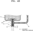
- FIG. 4B is a partially enlarged view illustrating another aspect of the aerosol generating device according to the embodiment.
- the aerosol generating device 1000 may further include the second valve 60 that controls opening and closing of the outlet 20 to control transfer of a medium stored in the canister 10 to the transfer tube 30.
- the second valve 60 may open or close the outlet 20 of the canister 10 while moving between, for example a first position P1 and a second position P2.
- the second valve 60 may close the outlet 20 of the canister 10 when located in the first position P1.
- the inside of the canister 10 is in a relatively high pressure state, and thus, a medium in the canister 10 tends to move to the outside, but an outward movement of the medium may be blocked by the second valve 60 that closes the outlet 20.
- the second valve 60 may include a body portion 61 for controlling opening and closing of the outlet 20 and a locking portion 62 for limiting a movement range of the body portion 61.
- the locking portion 62 may be caught on the inside of the canister 10 to prevent the body portion 61 from being separated from the canister 10 by an internal pressure of the canister 10. That is, the locking portion 62 may prevent the outlet 20 from being opened by the second valve 60 due to a pressure inside the canister 10 causing the second valve 60 to deviate from a movement range.
- the second valve 60 may further include an elastic portion (not illustrated) for maintaining a closed state of the outlet 20 when the aerosol generating device 1000 is not in use.
- the second valve 60 may open the outlet 20 of the canister 10 when located in the second position P2.
- the second valve 60 may move from the first position P1 to the second position P2 when one side thereof is pressurized.
- a gap 21 may be made such that the outlet 20 communicates with the transfer tube 30, and the medium stored in the canister 10 may be transferred to the transfer tube 30 through the gap 21.
- An opening/closing mechanism of the outlet 20 by the second valve 60 is not limited to the method described above, and it may be understood by those skilled in the art related to the present embodiment that various opening/closing mechanisms such as a rotary opening/closing mechanism may be applied to the aerosol generating device 1000 according to the embodiment.
- the canister 10, the transfer tube 30, and the second valve 60 may form an integral unit, and when any one of the canister 10, the transfer tube 30, and the second valve 60 has reduced durability or a failure, components of the integral unit may be replaced individually, or all the components may be replaced.
- the second valve 60 may be operated by a user, and the medium stored in the canister 10 may be transferred to the transfer tube 30 in response to an operation of a user for the second valve 60 to open the outlet 20.
- a user may pressurize the second valve 60 to move from the first position P1 to the second position P2.
- the aerosol generating device 1000 may further include a button 70 for controlling an operation of the second valve 60.
- the button 70 may be implemented by a physical button or a capacitive touch sensor.
- the operation of the second valve 60 may be mechanically controlled according to an operation of the button 70.
- the button 70 connected to the second valve 60 is pressed, one end of the second valve 60 is pressurized, and thus the outlet 20 may be opened.
- the operation of the second valve 60 may be electrically adjusted according to the operation of the button 70.
- an electromagnet for applying a magnetic force to the second valve 60 may be electrically connected to a battery for supplying a current to the electromagnet. That is, the button 70 may serve as a switch for connecting the battery to the electromagnet.
- a current may be applied to the electromagnet, and the electromagnet may generate a magnetic field that applies a magnetic force to the second valve 60 such that one end of the second valve 60 is pressurized, and then the outlet 20 may be opened.
- the button 70 may be physically or electrically connected to the second valve 60, and when a user operates the button 70, the button 70 may move from the first position P1 to the second position P2 or from the second position P2 to the first position P1 in order to adjust opening and closing of the outlet 20 of the canister 10.
- the button 70 may be in a housing that forms an exterior of the aerosol generating device 1000.
- the housing may indicate an external case for protecting a main body thereof from an external impact.
- the button 70 may be at one end on a lower side of the aerosol generating device 1000.
- the button 70 may be at the outer peripheral surface of the aerosol generating device 1000.
- a user may conveniently control an operation of the second valve 60 by pressing the button 70 while holding the aerosol generating device 1000.
- the amount of medium transferred to the transfer tube 30 may be determined based on at least one of an operation time and an operation strength of the button 70.
- the medium transferred to the transfer tube 30 may not be discharged directly to the outside of the aerosol generating device 1000 and may be discharged to the outside of the aerosol generating device 1000 under the condition that the first valve 40 is open, and thus, a user may directly operate the button 70 such that a desired amount of medium is transferred from the canister 10 to the transfer tube 30.
- a user may preliminarily determine the amount of aerosol to be generated before puffing on the aerosol generating device 1000 by directly controlling opening and closing of the second valve 60. Accordingly, a user may directly control the amount of aerosol ejected to the outside of the aerosol generating device 1000 when the first valve 40 is opened.
- a movement process of a medium may be divided into a movement process from the canister 10 to the transfer tube 30 and a movement process from the transfer tube 30 to the nozzle 50, and the first and second valves 40 and 60 for controlling the two movement processes may be operated or controlled by a user.
- a user may open the second valve 60 before puffing on the aerosol generating device 1000 to allow a preset amount of medium to move from the canister 10 to the transfer tube 30, and by puffing on the aerosol generating device 1000 to open the first valve 40 when generating an aerosol, the medium remaining in the transfer tube 30 may move to the nozzle 50.
- the aerosol generating device 1000 includes the first valve 40 and the second valve 60, and thus, a possibility of leakage of the medium in the aerosol generating device 1000 may be doubly blocked, and a user may have the desired amount of aerosol generated at desired timing.
- the aerosol generating device 1000 may have cross-sectional shape, such as a circular shape, an oval shape, a square shape, a rectangular shape, or a polygonal shape, in a direction crossing a longitudinal direction of a main body thereof.
- the cross-sectional shape of the aerosol generating device 1000 is not limited to the shapes described above, and the aerosol generating device 1000 is not limited to a linearly extending structure when extending in the longitudinal direction.
- the cross-sectional shape of the aerosol generating device 1000 may be curved in a streamline shape for a user's hand grip or may be bent at a preset angle in a specific region to extend long, and the cross-sectional shape of the aerosol generating device 1000 may change in the longitudinal direction.
- FIG. 5 is a view schematically illustrating an aerosol generating device according to another embodiment.
- an aerosol generating device 2000 may include a mouthpiece 200, a main body 100, a canister 10, an outlet 20, a transfer tube 30, a first valve 40, a nozzle 50, a second valve 60, a button 70, a battery 510, a sensor 520, a user interface 530, a memory 540, and a processor 550.
- the aerosol generating device 2000 illustrated in FIG. 5 may be different from the aerosol generating device 2000 illustrated in FIG. 3 in that some hardware components are added thereto, and descriptions overlapping the content described in FIG. 3 are omitted, and the added components will be mainly described.
- the hardware components may be arranged on a lower side of the aerosol generating device 2000 but is not limited to the configuration illustrated in FIG. 5 . It may be understood by those skilled in the art related to the present embodiment that an arrangement of the configuration of the aerosol generating device 2000 may be changed according to a design of the aerosol generating device 2000.
- the battery 510 may supply power that is used to operate the aerosol generating device 2000.
- the battery 510 may supply power required for operations of other hardware components included in the aerosol generating device 2000, that is, the sensor 520, the user interface 530, the memory 540, and the processor 550.
- the battery 510 may include a rechargeable battery or a disposable battery.
- the battery 510 may include a nickel-based battery (for example, a nickel-metal hydride battery or a nickel-cadmium battery) or a lithium-based battery (for example, a lithium-cobalt battery, a lithium-phosphate battery, a lithium titanate battery, a lithium-ion battery, or a lithium-polymer battery).
- a nickel-based battery for example, a nickel-metal hydride battery or a nickel-cadmium battery
- a lithium-based battery for example, a lithium-cobalt battery, a lithium-phosphate battery, a lithium titanate battery, a lithium-ion battery, or a lithium-polymer battery.
- the type of the battery 510 that may be used in the aerosol generating device 2000 is not limited to the battery described above.
- the battery 510 may include an alkaline battery or a manganese battery as needed.
- the aerosol generating device 2000 may include at least one sensor 520.
- a result detected by the at least one sensor 520 may be transmitted to the processor 550, and according to the detected result, the processor 550 may control the aerosol generating device 2000 to perform various functions such as displaying a notification.
- the at least one sensor 520 may include a puff detection sensor.
- the puff detection sensor may detect a user's puff based on at least one of a change in a flow rate, a change in pressure, and detection of a sound of an externally introduced airflow.
- the puff detection sensor may detect a start timing and an end timing of a user's puff, and the processor 550 may determine a puff period and a non-puff period according to the detected start timing and end timing of the puff.
- the aerosol generating device 2000 may further include a puff detection sensor for detecting a user's puff, and the first valve 40 may operate based on a result detected by the puff detection sensor.
- the first valve 40 may include a solenoid valve, and the solenoid valve may operate based on the result detected by the puff detection sensor.
- the solenoid valve may generate a magnetic force based on a user's puff detected by the puff detection sensor. For example, a result detected by the puff detection sensor may be transferred to the processor 550, and the processor 550 may control a current supplied from the battery 510 to the solenoid valve based on the detected result.
- the inside of the solenoid valve may include a moving body that is movable by an applied magnetic force.
- a magnetic force is not applied to the moving body, and thus, the moving body may be maintained in a position in which a flow path inside the solenoid valve is closed, and when the user's puff is detected, a magnetic force is applied to the moving body, and thus, the moving body may move from a position in which the flow path is closed to a position in which the flow path is opened.
- the at least one sensor 520 may include a user input sensor.
- the user input sensor may be a sensor, which receives a user's input, such as a switch, a physical button, or a touch sensor.
- the touch sensor may include a capacitive sensor that may detect a user's input by detecting a change in capacitance generated when the user touches a preset region formed of a metal material.
- the processor 550 may determine whether there is a user's input by comparing values before and after the change in capacitance received from the capacitive sensor. When the value before and after the change in capacitance exceeds a preset threshold, the processor 550 may determine that there is a user's input.
- the at least one sensor 520 may include a motion sensor.
- Information on movement of the aerosol generating device 2000 such as inclination, movement speed, and acceleration of the aerosol generating device 2000, may be acquired by the motion sensor.
- the motion sensor may detect information on a moving state of the aerosol generating device 2000 is moving, a stationary state of the aerosol generating device 2000, a state in which the aerosol generating device 2000 is inclined at an angle in a preset range for puff, and a state in which the aerosol generating device 2000 is inclined at an angle different from an angle formed during a puff operation between respective puff operations.
- the motion sensor may detect motion information of the aerosol generating device 2000 by using various methods known in the art.
- the motion sensor may include an acceleration sensor that may detect acceleration in three directions of an x-axis, a y-axis, and a z-axis, and a gyro sensor that may detect angular velocity in the three directions.
- the memory 540 may include hardware for storing various data processed by the aerosol generating device 2000, and the memory 540 may store data processed by the processor 550 and data to be processed thereby.
- the memory 540 may include various types of memory, for example, random access memory (RAM) such as dynamic random access memory (DRAM) or static random access memory (SRAM), read-only memory (ROM), electrically erasable programmable read-only memory (EEPROM), and so on.
- RAM random access memory
- DRAM dynamic random access memory
- SRAM static random access memory
- ROM read-only memory
- EEPROM electrically erasable programmable read-only memory
- the memory 540 may store an operating time, a greatest number of puffs, a current number of puffs of the aerosol generating device 2000, and data on a user's smoking pattern.
- the processor 550 controls all operations of the aerosol generating device 2000.
- the processor 550 may also be implemented by an array of a plurality of logic gates or may also be implemented by a combination of a general-purpose microprocessor 550 and a memory unit that stores a program executable by the microprocessor 550.
- the processor 550 may also be implemented by other types of hardware.
- the processor 550 may analyze a result detected by the at least one sensor 520 and control subsequent processing to be performed. For example, the processor 550 may control opening and closing of the first valve 40 and/or the second valve 60 based on a result detected by at least one sensor.
- the embodiment may also be implemented in the form of a recording medium including instructions executable by a computer such as a program module to be executed by a computer.
- Computer-readable media may be any available media accessible by a computer and include both volatile and nonvolatile media and removable and non-removable media.
- the computer-readable media may include both computer storage media and communication media.
- the computer storage media may include both volatile and nonvolatile media and removable and non-removable media implemented by any method or technology for storing information such as computer readable instructions, data structures, program modules or other data.
- the communication media typically include computer readable instructions, other data in modulated data signals such as program modules, or other transmission mechanisms, and include any information transfer media.
- FIG. 6A is a view illustrating an air-atomizing nozzle according to an embodiment
- FIG. 6B is a view illustrating an air-atomizing nozzle according to another embodiment.
- air-atomizing nozzles 50a and 50b may respectively include outdoor air passages 52a and 52b through which external air is introduced.
- the air-atomizing nozzles 50a and 50b may respectively include at least one outdoor air passage 52a and at least one outdoor air passage 52b through which external air is introduced, and a medium and external air may be mixed on the inside or outside of the nozzles 50a and 50b.
- the air-atomizing nozzle 50a may include at least one medium passage 51a and the outdoor air passage 52a, and the medium passage 51a may be in fluid communication with the outdoor air passage 52a on the inside of the nozzle 50a. Accordingly, a medium moving to the outside of the nozzle 50a through the medium passage 51a may be mixed or collide with the external air introduced into the nozzle 50a in one region inside the nozzle 50a.
- the air-atomizing nozzle 50b may include at least one medium passage 51b and the outdoor air passage 52b, and the medium passage 51b and the outdoor air passage 52b may extend to the end of the nozzle 50b from which an aerosol is ejected, and the medium passage 51b may be in fluid communication with the outside air passage 52b on the outside of the end of the nozzle 50b from which the aerosol is ejected. Accordingly, a medium and external air discharged through the nozzle 50b may be mixed or collide with external air on the outside of the end of the nozzle 50b.
- media passing through the air-atomizing nozzles 50a and 50b may be mixed or collide with external air on the inside or outside of the nozzles 50a and 50b, and thus, an aerosol having smaller particles may be effectively generated.
Landscapes
- Chemical & Material Sciences (AREA)
- Engineering & Computer Science (AREA)
- Dispersion Chemistry (AREA)
- Mechanical Engineering (AREA)
- Health & Medical Sciences (AREA)
- Chemical Kinetics & Catalysis (AREA)
- General Chemical & Material Sciences (AREA)
- Medicinal Chemistry (AREA)
- Pharmacology & Pharmacy (AREA)
- Epidemiology (AREA)
- Life Sciences & Earth Sciences (AREA)
- Animal Behavior & Ethology (AREA)
- General Health & Medical Sciences (AREA)
- Public Health (AREA)
- Veterinary Medicine (AREA)
- Human Computer Interaction (AREA)
- Containers And Packaging Bodies Having A Special Means To Remove Contents (AREA)
Abstract
Description
- Embodiments relate to an aerosol generating device, and more particularly, to an aerosol generating device that ejects an aerosol by using a canister in which nicotine and a propellant are stored.
- There is increasing demand for aerosol generating devices that generate aerosol in a non-combustion method as an alternative to burning cigarettes to generate aerosols. For example, the aerosol generating device is a device that generates aerosols in a non-combustion method from an aerosol generating material and supplies aerosols to a user or performs a function of generating an aerosol having a flavor by passing a vapor generated from the aerosol generating material through a fragrance medium.
- For example, the non-combustion method of generating an aerosol may include a method of ejecting the aerosol by applying a high pressure to a liquid aerosol generating material to allow the liquid to pass through a nozzle. In another example, there may be a method of generating an aerosol by storing a propellant that is easily vaporized at a room temperature in a high-pressure canister together with an aerosol generating material and by allowing the propellant to be ejected out of the canister together with the aerosol generating material when an outlet of the canister is opened.
- According to the non-combustion method, the aerosol generating device may not include a separate atomizer.
- In an aerosol generating device using a method of ejecting an aerosol from a canister, smooth discharge of a liquid from the canister may be important in aerosol generating performance. In order for the liquid in the canister to be easily discharged regardless of conditions of the canister (for example, the amount of liquid remaining in the canister and a degree of inclination of the canister), the aerosol generating device may be designed to have a structure in which an outlet of the canister is arranged in a direction in which gravity acts (for example, a lower portion of the aerosol generating device).
- In this case, a mouthpiece used when a user puffs on an aerosol generating device may also be under the aerosol generating device to be adjacent to the outlet of the canister. Accordingly, an aerosol generating device having a structure in which the mouthpiece is under the aerosol generating device from a user's point of view may be provided.
- The aerosol generating device having the structure may provide unfamiliarity and discomfort to a user because a mouthpiece is in the direction facing the ground. Accordingly, an aerosol generating device having a structure in which a liquid in a canister is easily discharged but a mouthpiece is in an opposite direction to an outlet of the canister may be required.
- Embodiments provide an aerosol generating device including an outlet arranged in a lower portion of a canister and a mouthpiece arranged in an upper portion of the aerosol generating device.
- The technical problems of the present disclosure are not limited to the above-described description, and other technical problems may be clearly understood by one of ordinary skill in the art from the present specification and the attached drawings.
- An aerosol generating device according to one embodiment may include a mouthpiece configured to come into contact with a mouth of a user, a canister storing a medium including nicotine and a propellant, and including an outlet which is on an opposite side of the mouthpiece and through which the medium flows out, a transfer tube having a first end portion connected to the outlet and a second end portion connected to the mouthpiece, and configured to receive the medium from the canister at the first end portion, a first valve arranged at the second end portion and configured to control discharge of the medium remaining in the transfer tube to the outside, and a nozzle configured to atomize the medium and eject an aerosol when the first valve is open.
- An aerosol generating device according to the embodiment described above includes an outlet of a canister which is downward to the aerosol generating device and a mouthpiece which is upward to the aerosol generating device, and thus, a liquid stored in the canister may be smoothly discharged, and user convenience may be obtained.
- In addition, the aerosol generating device according to the embodiment described above includes a valve for opening and closing the outlet of the canister, and thus, the amount of medium discharged from the canister may be precisely controlled, and the amount of aerosol that is generated may be controlled according to needs of a user.
- The effects of the present disclosure are not limited to the above effects, and effects that are not mentioned could be clearly understood by one of ordinary skill in the art from the present specification and the attached drawings.
-
-
FIG. 1A is a view schematically illustrating an aerosol generating device of a known embodiment. -
FIG. 1B is a view schematically showing an aerosol generating device of another known embodiment. -
FIG. 2 is a view schematically illustrating an aerosol generating device according to an embodiment. -
FIG. 3 is a view schematically illustrating an aerosol generating device of another embodiment. -
FIG. 4A is a partially enlarged view illustrating an aspect of an aerosol generating device according to an embodiment. -
FIG. 4B is a partial enlarged view illustrating another aspect of the aerosol generating device according to the embodiment. -
FIG. 5 is a view schematically illustrating an aerosol generating device of another embodiment. -
FIG. 6A is a view illustrating an air-atomizing nozzle according to an embodiment. -
FIG. 6B is a view illustrating an air-atomizing nozzle according to another embodiment. - With respect to the terms used to describe the various embodiments, general terms which are currently and widely used are selected in consideration of functions of structural elements in the various embodiments of the present disclosure. However, meanings of the terms can be changed according to intention, a judicial precedence, the appearance of new technology, and the like. In addition, in certain cases, a term which is not commonly used can be selected. In such a case, the meaning of the term will be described in detail at the corresponding portion in the description of the present disclosure. Therefore, the terms used in the various embodiments of the present disclosure should be defined based on the meanings of the terms and the descriptions provided herein.
- In addition, unless explicitly described to the contrary, the word "comprise" and variations such as "comprises" or "comprising" will be understood to imply the inclusion of stated elements but not the exclusion of any other elements. In addition, the terms "-er", "-or", and "module" described in the specification mean units for processing at least one function and/or operation and can be implemented by hardware components or software components and combinations thereof.
- As used herein, expressions such as "at least one of," when preceding a list of elements, modify the entire list of elements and do not modify the individual elements of the list. For example, the expression, "at least one of a, b, and c," should be understood as including only a, only b, only c, both a and b, both a and c, both b and c, or all of a, b, and c.
- As will be described below, embodiments of the present disclosure will be described in detail with reference to the accompanying drawings so that those skilled in the art may easily implement the embodiments in the technical fields of the present disclosure. However, the embodiments of the present disclosure may be implemented in various different forms and are not limited to the embodiments described herein.
- In addition, terms including an ordinal number such as 'first' or 'second' used in this specification may be used to describe various components, but the components should not be limited by the terms. The terms are used only for the purpose of distinguishing one component from another.
- In addition, some of the components in the drawings may be illustrated with a somewhat exaggerated size or ratio. In addition, the components illustrated in some drawings may not be illustrated in other drawings.
- In addition, throughout the specification, a "longitudinal direction" of a component may indicate a direction in which the component extends along one axis thereof, in which case, one direction axis of the component may indicate a direction in which the component extends longer than another direction axis crossing the one-direction axis. For example, the longitudinal direction may indicate a direction parallel to another direction in which the transfer tube illustrated in
FIG. 2 extends. - In addition, throughout the specification, an "upper portion" may indicate one end portion in the +y direction of the aerosol generating device illustrated in the drawings, and a "lower portion" may indicate one end portion in the -y direction. For example, in
FIG. 2 , a mouthpiece is in an upper portion of an aerosol generating device, and an outlet is in a lower portion of the aerosol generating device. - In addition, throughout the specification, "puff" refers to a user's inhalation, and the inhalation may refer to a situation in which something is drawn into a user's oral cavity, nasal cavity, or lungs through the user's mouth or nose.
- In addition, throughout the specification, an "aerosol" refers to a material in which liquid and/or solid microparticles are dispersed in a gas. Aerosol may refer to a state in which vaporized particles generated from an aerosol generating material and air are mixed. For example, a phase of an aerosol generating material may be transformed into a gaseous phase through vaporization and/or sublimation. An aerosol may be generated by atomizing and releasing an aerosol generating material in a liquid and/or solid phase.
- Throughout the specification, an "embodiment" is a certain distinction for easily describing the disclosure, and respective embodiments are not necessarily mutually exclusive. For example, configurations disclosed in one embodiment may be applied and/or implemented in other embodiments and may be modified and applied and/or implemented without departing from the scope of the disclosure.
- In addition, the terms used in the present disclosure is for describing the embodiments and is not intented to limit the embodiments of the present disclosure. In the present disclosure, the singular also includes the plural unless otherwise specified.
- Hereinafter, embodiments of the present disclosure will be described in detail with reference to the drawings.
-
FIG. 1A is a view schematically illustrating an aerosol generating device according to a known embodiment, andFIG. 1B is a view schematically illustrating an aerosol generating device according to another known embodiment. - Referring to
FIGS. 1A and1B ,aerosol generating devices mouthpiece 200, amain body 100, acanister 3, anoutlet 4, and anozzle 5. - In the
aerosol generating device 10000a according to the known embodiment illustrated inFIG. 1A , themouthpiece 200 is at one end on an opposite side (for example, an upper portion of the aerosol generating device) of a direction in which gravity acts, and theoutlet 4 of thecanister 3 may also be located adjacent to themouthpiece 200. Here, a direction opposite to the direction in which gravity acts may be, for example, a +y direction. - The
canister 3 may include a propellant and an aerosol generating material. The inside of thecanister 3 is maintained at a high pressure such that the propellant and the aerosol generating material included in the inside of thecanister 3 may be maintained in a liquid state. - A material in the liquid state stored in the
canister 3 having the structure illustrated inFIG. 1A may be affected by being discharged to the outside according to a condition of thecanister 3. The condition of thecanister 3 may include, for example, the remaining amount of an internal liquid, a position of aninner tube 6, an internal pressure, a degree of inclination to the ground, and so on, and the condition of thecanister 3 may affect discharge of a liquid material stored in thecanister 3. - That is, the
canister 3, in which theoutlet 4 is on the opposite side to the direction in which gravity acts, does not easily discharge the liquid therein, and thus, functionality and reliability of theaerosol generating device 10000a may be reduced. In order to solve this problem, a structure of thecanister 3 illustrated inFIG. 1B may be proposed. - In the
aerosol generating device 10000b according to another known embodiment illustrated inFIG. 1B , in order for a liquid material to be easily discharged to the outside of thecanister 3, theoutlet 4 may be at one end of thecanister 3 in a direction in which gravity acts (for example, a lower portion of the aerosol generating device). Here, the direction in which gravity acts may be, for example, a -y direction. - As the
outlet 4 of thecanister 3 is in the lower portion of thecanister 3, a liquid in thecanister 3 may be easily discharged to the outside of thecanister 3 without being affected by conditions of thecanister 3 described above. - As the
canister 3 has the structure illustrated inFIG. 1B , themouthpiece 200 may also be at the lower portion of theaerosol generating device 10000b to be adjacent to theoutlet 4 of thecanister 3. - The
aerosol generating device 10000b having the structure illustrated inFIG. 1B has an advantage that a liquid in thecanister 3 is easily discharged compared to theaerosol generating device 10000a having the structure illustrated inFIG. 1A but may cause discomfort or unfamiliarity to a user because themouthpiece 200 is in a direction toward the ground. Accordingly, there may be needed an aerosol generating device having a structure in which theoutlet 4 of thecanister 3 is in a lower portion of an aerosol generating device and themouthpiece 200 is in an upper portion of the aerosol generating device. -
FIG. 2 is a view schematically illustrating an aerosol generating device according to an embodiment, andFIG. 3 is a view schematically illustrating an aerosol generating device according to another embodiment. - Referring to FIGS.
FIGS. 2 and3 , anaerosol generating device 1000 according to the embodiment may include amouthpiece 200, amain body 100, acanister 10, anoutlet 20, atransfer tube 30, afirst valve 40, anozzle 50, asecond valve 60, and abutton 70. An arrangement of thetransfer tube 30 is changed in theaerosol generating device 1000 illustrated inFIG. 3 compared to theaerosol generating device 1000 illustrated inFIG. 2 . - A configuration of the
aerosol generating device 1000 is not limited to the configurations illustrated inFIGS. 2 and3 . According to a design of theaerosol generating device 1000, some of the components illustrated inFIGS. 2 and3 may be omitted or a new configuration may be added thereto, which may be understood by those skilled in the art related to the present embodiment. - The
mouthpiece 200 may be at one end of theaerosol generating device 1000. For example, theaerosol generating device 1000 may be assembled by combining themain body 100 with themouthpiece 200, and themouthpiece 200 may be at one end in the +y direction, which is an upper portion of theaerosol generating device 1000. - The
mouthpiece 200 is a portion to be inserted into a user's oral cavity. Themouthpiece 200 may include adischarge hole 210 for discharging an aerosol generated from the aerosol generating material in thecanister 10 to the outside. - At least one region of the
mouthpiece 200 may include anoutdoor air inlet 220. Theoutdoor air inlet 220 is a passage through which external air may be introduced into theaerosol generating device 1000. - The external air introduced through the
outdoor air inlet 220 may be introduced into a space in which an aerosol is generated. Accordingly, external air may be continuously introduced into theaerosol generating device 1000 through theoutdoor air inlet 220, and thus, a user may perform continuous puff. - The
canister 10 may store a medium comprising a propellant and an aerosol generating material. Thecanister 10 may be made of a material capable of endure a high pressure. For example, thecanister 10 may be made of a metal or an alloy material but is not limited thereto. - The
canister 10 may store a propellant in any one state among a liquid state, a solid state, a gaseous state, and a gel state, and an aerosol generating material. - The propellant may include at least one of hydrofluoroalkane (HFA) and chlorofluorocarbon (CFC), and the aerosol generating material may include a liquid composition. For example, the liquid composition may be a liquid including a tobacco material including a volatile tobacco flavor component or may also be a liquid including a non-tobacco material.
- The liquid composition may include any one component among, for example, water, a solvent, ethanol, a plant extract, a fragrance, a flavoring agent, and a vitamin mixture, or a mixture of the components. The fragrance may include menthol, peppermint, spearmint oil, various fruit flavoring ingredients, and so on but is not limited thereto. The flavoring agent may include ingredients capable of providing a user with a variety of flavors or savors. The vitamin mixture may include a mixture of at least one of vitamin A, vitamin B, vitamin C, and vitamin E but is not limited thereto. In addition, the liquid composition may include an aerosol former such as glycerin and propylene glycol.
- For example, the liquid composition may include a solution of glycerin and propylene glycol in any weight ratio, to which a nicotine salt is added. The liquid composition may also include two or more nicotine salts. The nicotine salt may be formed by adding a suitable acid including organic or inorganic acid to nicotine. The nicotine may include either naturally generated nicotine or synthetic nicotine and may have concentration of any suitable weight to the total solution weight of the liquid composition.
- Acid for forming the nicotine salt may be appropriately selected by considering a blood nicotine absorption rate, an operating temperature of the
aerosol generating device 1000, flavor or savor, solubility, and so on. For example, the acid for forming the nicotine salt may include benzoic acid, lactic acid, salicylic acid, lauric acid, sorbic acid, levulinic acid, pyruvic acid, formic acid, acetic acid, propionic acid, butyric acid, valeric acid, caproic acid, caprylic acid, capric acid, citric acid, myristic acid, palmitic acid, stearic acid, oleic acid, linoleic acid, linolenic acid, phenylacetic acid, tartaric acid, succinic acid, fumaric acid, gluconic acid, saccharinic acid, malonic acid, malic acid, a single acid selected from a group consisting of above acids, or a mixture of two or more acids selected from the group, but is not limited thereto. - According to one embodiment, the
canister 10 may store a medium including nicotine and a propellant and may include theoutlet 20 which is on an opposite side of themouthpiece 200 and through which the medium flows out. For example, thecanister 10 may include a first end portion facing themouthpiece 200 and a second end portion opposite to the first end, and theoutlet 20 may be at the second end portion. - A medium including a propellant and an aerosol generating material may be maintained in a liquid state in the
canister 10 under a high pressure condition. When theoutlet 20 of thecanister 10 is open, the propellant included in the medium is vaporized or expanded, and thus, the medium may flow out or may be discharged to the outside of thecanister 10. - The
transfer tube 30 may receive the medium that flows out or is discharged from thecanister 10. In one embodiment, thetransfer tube 30 may include one end portion connected to theoutlet 20 of thecanister 10 and the other end portion connected to themouthpiece 200, and the one end portion may receive a medium transferred from thecanister 10. - The
transfer tube 30 may be made of a material that may endure a pressure of the vaporized or expanded medium. For example, thetransfer tube 30 may be made of a metal material (for example, aluminum or stainless steel) that may be maintained in a fixed shape. In another example, thetransfer tube 30 may also be made of a material (for example, thermoplastic polyurethane) with excellent food hygiene. - The medium transferred from the
canister 10 to thetransfer tube 30 may temporarily stay in thetransfer tube 30 before being discharged to the outside of theaerosol generating device 1000. For example, thefirst valve 40 in the other end portion of thetransfer tube 30 may control that the medium transferred to thetransfer tube 30 is discharged to the outside of theaerosol generating device 1000. Thefirst valve 40 permits or blocks the medium remaining in thetransfer tube 30 from being discharged to the outside of theaerosol generating device 1000, and a more detailed description thereof will be described below. - According to one embodiment, a diameter and a length of the
transfer tube 30 may be designed based on a user's aerosol puff amount. For example, the diameter and length of thetransfer tube 30 may be designed based on the amount of medium required for one puff or one smoking by a user. - As at least one of the diameter and length of the
transfer tube 30 increases, a volume of thetransfer tube 30 increases, and thus, the greatest amount of a medium that may stay in thetransfer tube 30 may increase. That is, by adjusting the diameter and length of thetransfer tube 30, the amount of aerosol generated by theaerosol generating device 1000 per puff or per smoking may be changed. - In this way, the
transfer tube 30 may connect theoutlet 20 and themouthpiece 200 of thecanister 10 to each other, which are separated from each other, to transfer the medium inside theaerosol generating device 1000, and the amount of aerosol generated by theaerosol generating device 1000 may be adjusted or changed for a user according to the design of thetransfer tube 30. - According to the embodiment illustrated in
FIG. 2 , thetransfer tube 30 may extend along an outer peripheral surface of thecanister 10. For example, thetransfer tube 30 may extend in a straight line or a curved line from the one end portion connected to theoutlet 20 to the other end portion connected to themouthpiece 200 along the outer peripheral surface in a state of being separated from the outer peripheral surface of thecanister 10 by a preset distance. In another example, thetransfer tube 30 may also extend in a straight line or a curved line from the one end portion connected to theoutlet 20 to the other end portion connected to themouthpiece 200 along the outer peripheral surface in a state of being in contact with the outer peripheral surface of thecanister 10. - According to another embodiment illustrated in
FIG. 3 , thetransfer tube 30 may be spirally wound along the outer peripheral surface of thecanister 10. Here, "winding spirally along an outer peripheral surface of a canister" means that thetransfer tube 30 is wound around thecanister 10 along the outer peripheral surface of thecanister 10 in a shape corresponding to the shape of thecanister 10. For example, thecanister 10 may have a cylindrical shape, a triangular prism shape, a square prism shape, or a polygonal prism shape, and thetransfer tube 30 may be wound in a shape corresponding to the shape of thecanister 10, for example, a circular spiral, a triangular spiral, a square spiral, or a polygonal spiral. - In one embodiment, the
canister 10 and thetransfer tube 30 may be integrated with each other. For example, thetransfer tube 30 may be wound along the outer peripheral surface of thecanister 10 to pressurize the outer peripheral surface of thecanister 10. In another example, at least a part of thetransfer tube 30 may be bonded to the outer peripheral surface of thecanister 10. Specifically, thetransfer tube 30 may be bonded to thecanister 10 by welding, an adhesive, or so on such that thecanister 10 may be integrated with thetransfer tube 30. - As the
transfer tube 30 has a spiral structure, capacity of thetransfer tube 30 is greatly increased in the limited space in themain body 100, and thetransfer tube 30 may occupy an appropriate space, and thus, components in theaerosol generating device 1000 may be efficiently arranged. - In addition, a position of the
transfer tube 30 wound around thecanister 10 or integrated with thecanister 10 may be fixed when an external impact or so on is applied thereto, and thus, structural stability may be increased. - In another embodiment, the
transfer tube 30 may be formed in various shapes and may be arranged in a part in themain body 100 of theaerosol generating device 1000. For example, thetransfer tube 30 may be designed to have a preset diameter and a preset length as described above and may be arranged in a part in themain body 100 including a wound portion, a curled portion, or a tortuous portion. Accordingly, a space (or a volume) occupied by thetransfer tube 30 in themain body 100 may be reduced, and thus, space utilization inside themain body 100 may be increased. - The
first valve 40 may be arranged at the other end portion of thetransfer tube 30 to control discharge of a medium remaining in thetransfer tube 30 to the outside. For example, thefirst valve 40 may prevent a medium transferred from thecanister 10 to thetransfer tube 30 from leaking from thetransfer tube 30 to the outside of theaerosol generating device 1000 by closing the other end portion of thetransfer tube 30 when a user does not use theaerosol generating device 1000, and may allow the medium transferred to thetransfer tube 30 to be discharged to the outside of theaerosol generating device 1000 by opening the other end portion of thetransfer tube 30 when the user uses theaerosol generating device 1000. - In another example, the
first valve 40 may close a hole (or a vent) of thenozzle 50 to be described below when a user does not use theaerosol generating device 1000 and may open the hole of thenozzle 50 when the user uses theaerosol generating device 1000, and thereby, a medium may be discharged to the outside of theaerosol generating device 1000. That is, when thefirst valve 40 is open, a medium remaining in thetransfer tube 30 may pass through thenozzle 50 to be ejected to the outside. - According to one embodiment, the
first valve 40 may be opened based on a user's puff. For example, thefirst valve 40 may be opened when a user puffs on theaerosol generating device 1000 and may be closed when the user does not puff on theaerosol generating device 1000. That is, theaerosol generating device 1000 according to the embodiment may adjust generation of an aerosol based on a user's puff. - The
first valve 40 may include a mechanical operation valve that opens above a preset threshold pressure and closes below the preset threshold pressure. The mechanically operation valve may not be opened by a pressure of a medium staying in thetransfer tube 30 and may be opened only when a negative pressure is applied to the other end portion of thetransfer tube 30 according to the user's puff on theaerosol generating device 1000. - In one embodiment, the
first valve 40 may include a needle valve (or a "pintle"). The needle valve may have a shape (for example, a cone) having one end closed at an acute angle and may be displaced according to a change in pressure due to a user's puff on theaerosol generating device 1000 to open or close a hole thereof. For example, the other end portion of thetransfer tube 30 may be opened or closed based on an upward movement or a downward movement of the needle valve. In another example, a gap of the hole of thenozzle 50, which will be described later, may be opened or closed based on the upward movement or the downward movement of the needle valve. - The type of the
first valve 40 is not limited to the examples described above, and thefirst valve 40 may include an electromagnetic operation valve that operates based on a user's input. The electromagnetic operation valve may include, for example, a solenoid valve. When a user's puff or a user's operation is detected, the solenoid valve generates a magnetic force to open a flow path in the solenoid valve. - When the
first valve 40 is opened, thenozzle 50 may atomize a medium that is discharged to eject an aerosol. Thenozzle 50 may expand a fluid by increasing a flow rate of the fluid passing therethrough and decreasing a pressure thereof. For example, thenozzle 50 may have a shape in which a cross-sectional area thereof decreases along a direction in which a medium is discharged. As a medium passing through thenozzle 50 expands, sizes of particles are atomized and uniformized, and thereby, an aerosol may be ejected from an outlet of thenozzle 50. - A passage of the
nozzle 50 may have a preset length. Here, the preset length may indicate a length enough to allow a medium (or an aerosol) passing through the passage inside thenozzle 50 to be atomized into a sufficiently small size (for example, 10 µm in diameter). For example, thenozzle 50 may extend in a curved line from thefirst valve 40 by a preset length. - In one embodiment, the passage of the
nozzle 50 may include a curved portion. For example, the passage of thenozzle 50 may include a portion for changing a traveling direction of a medium. In another example, the passage of thenozzle 50 may also tortuously extend to have a preset length inside thenozzle 50. - As the length of the passage of the
nozzle 50 increases, a travel distance of a medium inside thenozzle 50 may increase. Accordingly, an average size of particles of an aerosol ejected from thenozzle 50 may be further reduced, and thus, a user may more smoothly inhale the aerosol. - According to one embodiment, the
nozzle 50 may include an air-atomizing nozzle that includes an outdoor air passage to mix an aerosol with outdoor air and eject the mixture. A more detailed description of the air-atomizing nozzle will be made below. - As described above, the
outlet 20 of thecanister 10 may be at the other end on a lower side of theaerosol generating device 1000, and themouthpiece 200 may be at one end on an upper side of theaerosol generating device 1000. Accordingly, problems of theaerosol generating devices FIGS. 1A and1B may be solved. - In one embodiment, the
nozzle 50 and themouthpiece 200 may be arranged in the same direction as each other. Thedischarge hole 210 included in themouthpiece 200 may be disposed in a direction parallel to the direction in which thenozzle 50 ejects the medium. - For example, the
nozzle 50 may be disposed to eject the medium in the +y direction, and thedischarge hole 210 of themouthpiece 200 may also be arranged in the +y direction. In another example, thenozzle 50 may be arranged to eject a medium in one direction between the +x direction and the +y direction, and thedischarge hole 210 of themouthpiece 200 may also be arranged in the same direction as thenozzle 50. - By matching a direction of the
nozzle 50 to a direction of thedischarge hole 210, an aerosol may be more smoothly transferred through themouthpiece 200 to a user using theaerosol generating device 1000. - Hereinafter, an operation of the
second valve 60 will be described in more detail with reference toFIGS. 4A and4B . -
FIG. 4A is a partially enlarged view illustrating an aspect of an aerosol generating device according to an embodiment, andFIG. 4B is a partially enlarged view illustrating another aspect of the aerosol generating device according to the embodiment. - Referring to
FIGS. 4A and4B , theaerosol generating device 1000 according to the embodiment may further include thesecond valve 60 that controls opening and closing of theoutlet 20 to control transfer of a medium stored in thecanister 10 to thetransfer tube 30. Thesecond valve 60 may open or close theoutlet 20 of thecanister 10 while moving between, for example a first position P1 and a second position P2. - In one aspect, the
second valve 60 may close theoutlet 20 of thecanister 10 when located in the first position P1. The inside of thecanister 10 is in a relatively high pressure state, and thus, a medium in thecanister 10 tends to move to the outside, but an outward movement of the medium may be blocked by thesecond valve 60 that closes theoutlet 20. - According to one embodiment, the
second valve 60 may include abody portion 61 for controlling opening and closing of theoutlet 20 and a lockingportion 62 for limiting a movement range of thebody portion 61. The lockingportion 62 may be caught on the inside of thecanister 10 to prevent thebody portion 61 from being separated from thecanister 10 by an internal pressure of thecanister 10. That is, the lockingportion 62 may prevent theoutlet 20 from being opened by thesecond valve 60 due to a pressure inside thecanister 10 causing thesecond valve 60 to deviate from a movement range. - In addition, the
second valve 60 may further include an elastic portion (not illustrated) for maintaining a closed state of theoutlet 20 when theaerosol generating device 1000 is not in use. - In another aspect, the
second valve 60 may open theoutlet 20 of thecanister 10 when located in the second position P2. Thesecond valve 60 may move from the first position P1 to the second position P2 when one side thereof is pressurized. When thesecond valve 60 moves to the second position P2, agap 21 may be made such that theoutlet 20 communicates with thetransfer tube 30, and the medium stored in thecanister 10 may be transferred to thetransfer tube 30 through thegap 21. - An opening/closing mechanism of the
outlet 20 by thesecond valve 60 is not limited to the method described above, and it may be understood by those skilled in the art related to the present embodiment that various opening/closing mechanisms such as a rotary opening/closing mechanism may be applied to theaerosol generating device 1000 according to the embodiment. - In addition, the
canister 10, thetransfer tube 30, and thesecond valve 60 may form an integral unit, and when any one of thecanister 10, thetransfer tube 30, and thesecond valve 60 has reduced durability or a failure, components of the integral unit may be replaced individually, or all the components may be replaced. - According to one embodiment, the
second valve 60 may be operated by a user, and the medium stored in thecanister 10 may be transferred to thetransfer tube 30 in response to an operation of a user for thesecond valve 60 to open theoutlet 20. For example, a user may pressurize thesecond valve 60 to move from the first position P1 to the second position P2. - Specifically, the
aerosol generating device 1000 according to the embodiment may further include abutton 70 for controlling an operation of thesecond valve 60. Here, thebutton 70 may be implemented by a physical button or a capacitive touch sensor. - For example, the operation of the
second valve 60 may be mechanically controlled according to an operation of thebutton 70. When thebutton 70 connected to thesecond valve 60 is pressed, one end of thesecond valve 60 is pressurized, and thus theoutlet 20 may be opened. - In another example, the operation of the
second valve 60 may be electrically adjusted according to the operation of thebutton 70. Specifically, when thebutton 70 is pressed, an electromagnet for applying a magnetic force to thesecond valve 60 may be electrically connected to a battery for supplying a current to the electromagnet. That is, thebutton 70 may serve as a switch for connecting the battery to the electromagnet. When thebutton 70 is pressed, a current may be applied to the electromagnet, and the electromagnet may generate a magnetic field that applies a magnetic force to thesecond valve 60 such that one end of thesecond valve 60 is pressurized, and then theoutlet 20 may be opened. - In this way, the
button 70 may be physically or electrically connected to thesecond valve 60, and when a user operates thebutton 70, thebutton 70 may move from the first position P1 to the second position P2 or from the second position P2 to the first position P1 in order to adjust opening and closing of theoutlet 20 of thecanister 10. - In one embodiment, the
button 70 may be in a housing that forms an exterior of theaerosol generating device 1000. Here, the housing may indicate an external case for protecting a main body thereof from an external impact. For example, thebutton 70 may be at one end on a lower side of theaerosol generating device 1000. In another example, thebutton 70 may be at the outer peripheral surface of theaerosol generating device 1000. - A user may conveniently control an operation of the
second valve 60 by pressing thebutton 70 while holding theaerosol generating device 1000. - Because the operation of the
second valve 60 is adjusted based on the operation of thebutton 70, the amount of medium transferred to thetransfer tube 30 may be determined based on at least one of an operation time and an operation strength of thebutton 70. - The medium transferred to the
transfer tube 30 may not be discharged directly to the outside of theaerosol generating device 1000 and may be discharged to the outside of theaerosol generating device 1000 under the condition that thefirst valve 40 is open, and thus, a user may directly operate thebutton 70 such that a desired amount of medium is transferred from thecanister 10 to thetransfer tube 30. - That is, a user may preliminarily determine the amount of aerosol to be generated before puffing on the
aerosol generating device 1000 by directly controlling opening and closing of thesecond valve 60. Accordingly, a user may directly control the amount of aerosol ejected to the outside of theaerosol generating device 1000 when thefirst valve 40 is opened. - Inside the
aerosol generating device 1000 according to the embodiments described above, a movement process of a medium may be divided into a movement process from thecanister 10 to thetransfer tube 30 and a movement process from thetransfer tube 30 to thenozzle 50, and the first andsecond valves - For example, a user may open the
second valve 60 before puffing on theaerosol generating device 1000 to allow a preset amount of medium to move from thecanister 10 to thetransfer tube 30, and by puffing on theaerosol generating device 1000 to open thefirst valve 40 when generating an aerosol, the medium remaining in thetransfer tube 30 may move to thenozzle 50. - In this way, the
aerosol generating device 1000 includes thefirst valve 40 and thesecond valve 60, and thus, a possibility of leakage of the medium in theaerosol generating device 1000 may be doubly blocked, and a user may have the desired amount of aerosol generated at desired timing. - The
aerosol generating device 1000 according to the embodiment described above may have cross-sectional shape, such as a circular shape, an oval shape, a square shape, a rectangular shape, or a polygonal shape, in a direction crossing a longitudinal direction of a main body thereof. However, the cross-sectional shape of theaerosol generating device 1000 is not limited to the shapes described above, and theaerosol generating device 1000 is not limited to a linearly extending structure when extending in the longitudinal direction. For example, the cross-sectional shape of theaerosol generating device 1000 may be curved in a streamline shape for a user's hand grip or may be bent at a preset angle in a specific region to extend long, and the cross-sectional shape of theaerosol generating device 1000 may change in the longitudinal direction. -
FIG. 5 is a view schematically illustrating an aerosol generating device according to another embodiment. - Referring to
FIG. 5 , anaerosol generating device 2000 according to another embodiment may include amouthpiece 200, amain body 100, acanister 10, anoutlet 20, atransfer tube 30, afirst valve 40, anozzle 50, asecond valve 60, abutton 70, abattery 510, asensor 520, auser interface 530, amemory 540, and aprocessor 550. - The
aerosol generating device 2000 illustrated inFIG. 5 may be different from theaerosol generating device 2000 illustrated inFIG. 3 in that some hardware components are added thereto, and descriptions overlapping the content described inFIG. 3 are omitted, and the added components will be mainly described. - The hardware components may be arranged on a lower side of the
aerosol generating device 2000 but is not limited to the configuration illustrated inFIG. 5 . It may be understood by those skilled in the art related to the present embodiment that an arrangement of the configuration of theaerosol generating device 2000 may be changed according to a design of theaerosol generating device 2000. - The
battery 510 may supply power that is used to operate theaerosol generating device 2000. In addition, thebattery 510 may supply power required for operations of other hardware components included in theaerosol generating device 2000, that is, thesensor 520, theuser interface 530, thememory 540, and theprocessor 550. Thebattery 510 may include a rechargeable battery or a disposable battery. - For example, the
battery 510 may include a nickel-based battery (for example, a nickel-metal hydride battery or a nickel-cadmium battery) or a lithium-based battery (for example, a lithium-cobalt battery, a lithium-phosphate battery, a lithium titanate battery, a lithium-ion battery, or a lithium-polymer battery). However, the type of thebattery 510 that may be used in theaerosol generating device 2000 is not limited to the battery described above. Thebattery 510 may include an alkaline battery or a manganese battery as needed. - The
aerosol generating device 2000 may include at least onesensor 520. A result detected by the at least onesensor 520 may be transmitted to theprocessor 550, and according to the detected result, theprocessor 550 may control theaerosol generating device 2000 to perform various functions such as displaying a notification. - For example, the at least one
sensor 520 may include a puff detection sensor. The puff detection sensor may detect a user's puff based on at least one of a change in a flow rate, a change in pressure, and detection of a sound of an externally introduced airflow. The puff detection sensor may detect a start timing and an end timing of a user's puff, and theprocessor 550 may determine a puff period and a non-puff period according to the detected start timing and end timing of the puff. - According to one embodiment, the
aerosol generating device 2000 may further include a puff detection sensor for detecting a user's puff, and thefirst valve 40 may operate based on a result detected by the puff detection sensor. For example, thefirst valve 40 may include a solenoid valve, and the solenoid valve may operate based on the result detected by the puff detection sensor. - The solenoid valve may generate a magnetic force based on a user's puff detected by the puff detection sensor. For example, a result detected by the puff detection sensor may be transferred to the
processor 550, and theprocessor 550 may control a current supplied from thebattery 510 to the solenoid valve based on the detected result. - In one embodiment, the inside of the solenoid valve may include a moving body that is movable by an applied magnetic force. When a user's puff is not detected, a magnetic force is not applied to the moving body, and thus, the moving body may be maintained in a position in which a flow path inside the solenoid valve is closed, and when the user's puff is detected, a magnetic force is applied to the moving body, and thus, the moving body may move from a position in which the flow path is closed to a position in which the flow path is opened.
- In addition, the at least one
sensor 520 may include a user input sensor. The user input sensor may be a sensor, which receives a user's input, such as a switch, a physical button, or a touch sensor. For example, the touch sensor may include a capacitive sensor that may detect a user's input by detecting a change in capacitance generated when the user touches a preset region formed of a metal material. Theprocessor 550 may determine whether there is a user's input by comparing values before and after the change in capacitance received from the capacitive sensor. When the value before and after the change in capacitance exceeds a preset threshold, theprocessor 550 may determine that there is a user's input. - In addition, the at least one
sensor 520 may include a motion sensor. Information on movement of theaerosol generating device 2000, such as inclination, movement speed, and acceleration of theaerosol generating device 2000, may be acquired by the motion sensor. For example, the motion sensor may detect information on a moving state of theaerosol generating device 2000 is moving, a stationary state of theaerosol generating device 2000, a state in which theaerosol generating device 2000 is inclined at an angle in a preset range for puff, and a state in which theaerosol generating device 2000 is inclined at an angle different from an angle formed during a puff operation between respective puff operations. The motion sensor may detect motion information of theaerosol generating device 2000 by using various methods known in the art. For example, the motion sensor may include an acceleration sensor that may detect acceleration in three directions of an x-axis, a y-axis, and a z-axis, and a gyro sensor that may detect angular velocity in the three directions. - The
memory 540 may include hardware for storing various data processed by theaerosol generating device 2000, and thememory 540 may store data processed by theprocessor 550 and data to be processed thereby. Thememory 540 may include various types of memory, for example, random access memory (RAM) such as dynamic random access memory (DRAM) or static random access memory (SRAM), read-only memory (ROM), electrically erasable programmable read-only memory (EEPROM), and so on. - The
memory 540 may store an operating time, a greatest number of puffs, a current number of puffs of theaerosol generating device 2000, and data on a user's smoking pattern. - The
processor 550 controls all operations of theaerosol generating device 2000. Theprocessor 550 may also be implemented by an array of a plurality of logic gates or may also be implemented by a combination of a general-purpose microprocessor 550 and a memory unit that stores a program executable by themicroprocessor 550. In addition, it may be understood by those skilled in the art that theprocessor 550 may also be implemented by other types of hardware. - The
processor 550 may analyze a result detected by the at least onesensor 520 and control subsequent processing to be performed. For example, theprocessor 550 may control opening and closing of thefirst valve 40 and/or thesecond valve 60 based on a result detected by at least one sensor. - The embodiment may also be implemented in the form of a recording medium including instructions executable by a computer such as a program module to be executed by a computer. Computer-readable media may be any available media accessible by a computer and include both volatile and nonvolatile media and removable and non-removable media. In addition, the computer-readable media may include both computer storage media and communication media. The computer storage media may include both volatile and nonvolatile media and removable and non-removable media implemented by any method or technology for storing information such as computer readable instructions, data structures, program modules or other data. The communication media typically include computer readable instructions, other data in modulated data signals such as program modules, or other transmission mechanisms, and include any information transfer media.
-
FIG. 6A is a view illustrating an air-atomizing nozzle according to an embodiment, andFIG. 6B is a view illustrating an air-atomizing nozzle according to another embodiment. - Referring to
FIGS. 6A and6B , air-atomizingnozzles outdoor air passages nozzles outdoor air passage 52a and at least oneoutdoor air passage 52b through which external air is introduced, and a medium and external air may be mixed on the inside or outside of thenozzles - In one embodiment, the air-atomizing
nozzle 50a may include at least onemedium passage 51a and theoutdoor air passage 52a, and themedium passage 51a may be in fluid communication with theoutdoor air passage 52a on the inside of thenozzle 50a. Accordingly, a medium moving to the outside of thenozzle 50a through themedium passage 51a may be mixed or collide with the external air introduced into thenozzle 50a in one region inside thenozzle 50a. - In another embodiment, the air-atomizing
nozzle 50b may include at least onemedium passage 51b and theoutdoor air passage 52b, and themedium passage 51b and theoutdoor air passage 52b may extend to the end of thenozzle 50b from which an aerosol is ejected, and themedium passage 51b may be in fluid communication with theoutside air passage 52b on the outside of the end of thenozzle 50b from which the aerosol is ejected. Accordingly, a medium and external air discharged through thenozzle 50b may be mixed or collide with external air on the outside of the end of thenozzle 50b. - As such, media passing through the air-atomizing
nozzles nozzles - Those of ordinary skill in the art related to the present embodiments may understand that various changes in form and details can be made therein without departing from the scope of the characteristics described above. The disclosed methods should be considered in a descriptive sense only and not for purposes of limitation. Therefore, the scope of the disclosure should be defined by the appended claims, and all differences within the scope equivalent to those described in the claims will be construed as being included in the scope of protection defined by the claims.
Claims (13)
- An aerosol generating device comprising:a mouthpiece configured to come into contact with a mouth of a user;a canister storing a medium including nicotine and a propellant, and including an outlet which is on an opposite side of the mouthpiece and through which the medium flows out;a transfer tube having a first end portion connected to the outlet and a second end portion connected to the mouthpiece, and configured to receive the medium from the canister at the first end portion;a first valve arranged at the second end portion and configured to control discharge of the medium remaining in the transfer tube to the outside; anda nozzle configured to atomize the medium and eject an aerosol when the first valve is open.
- The aerosol generating device of claim 1, wherein the first valve operates based on puff of the user.
- The aerosol generating device of claim 2, further comprising a puff detection sensor configured to detect the puff of the user,
wherein the first valve operates based on a result detected by the puff detection sensor. - The aerosol generating device of claim 1, further comprising a second valve configured to control transfer of the medium stored in the canister to the transfer tube by adjusting opening and closing of the outlet.
- The aerosol generating device of claim 4, whereinthe second valve is operated by the user, andthe medium stored in the canister is transferred to the transfer tube in response to an operation of the user for the second valve to open the outlet.
- The aerosol generating device of claim 5, wherein the second valve is movable between a first position in which the outlet is closed and a second position in which the outlet is opened.
- The aerosol generating device of claim 5, further comprising a button configured to control the operation of the second valve,
wherein an amount of the medium transferred to the transfer tube is determined based on at least one of an operation time and an operation strength of the button. - The aerosol generating device of claim 1, wherein a diameter and a length of the transfer tube is designed based on an aerosol puff amount of the user.
- The aerosol generating device of claim 1, wherein the transfer tube is spirally wound on an outer peripheral surface of the canister.
- The aerosol generating device of claim 1, wherein at least a part of the transfer tube is in contact with the outer peripheral surface of the canister.
- The aerosol generating device of claim 1, wherein the nozzle includes an air-atomizing nozzle including an outdoor air passage through which external air is introduced.
- The aerosol generating device of claim 1, wherein the nozzle includes a passage through which the medium passes, and the passage has a curved portion.
- The aerosol generating device of claim 1, whereinthe mouthpiece has a discharge hole for discharging the aerosol to the outside, andthe discharge hole is arranged in a direction parallel to another direction in which the nozzle ejects the medium.
Applications Claiming Priority (2)
| Application Number | Priority Date | Filing Date | Title |
|---|---|---|---|
| KR1020210074297A KR102686960B1 (en) | 2021-06-08 | 2021-06-08 | Aerosol generating device |
| PCT/KR2022/006291 WO2022260282A1 (en) | 2021-06-08 | 2022-05-03 | Aerosol generation device |
Publications (2)
| Publication Number | Publication Date |
|---|---|
| EP4124251A1 true EP4124251A1 (en) | 2023-02-01 |
| EP4124251A4 EP4124251A4 (en) | 2023-10-25 |
Family
ID=84363144
Family Applications (1)
| Application Number | Title | Priority Date | Filing Date |
|---|---|---|---|
| EP22772401.0A Pending EP4124251A4 (en) | 2021-06-08 | 2022-05-03 | Aerosol generation device |
Country Status (6)
| Country | Link |
|---|---|
| US (1) | US20240251881A1 (en) |
| EP (1) | EP4124251A4 (en) |
| JP (1) | JP7487972B2 (en) |
| KR (1) | KR102686960B1 (en) |
| CN (1) | CN115942887A (en) |
| WO (1) | WO2022260282A1 (en) |
Family Cites Families (9)
| Publication number | Priority date | Publication date | Assignee | Title |
|---|---|---|---|---|
| CN100381083C (en) | 2003-04-29 | 2008-04-16 | 韩力 | Electronic nonflammable spraying cigarette |
| CN2719043Y (en) * | 2004-04-14 | 2005-08-24 | 韩力 | Atomized electronic cigarette |
| GB0614621D0 (en) * | 2006-07-24 | 2006-08-30 | 3M Innovative Properties Co | Metered dose dispensers |
| NZ596456A (en) * | 2009-06-25 | 2014-01-31 | Boehringer Ingelheim Vetmed | Inhaler |
| US9814267B2 (en) * | 2012-09-28 | 2017-11-14 | Shenzhen Kimsen Technology Co., Ltd. | Electronic cigarette and electronic cigarette device thereof |
| DE102016002665A1 (en) * | 2016-03-08 | 2017-09-14 | Hauni Maschinenbau Gmbh | Electronic cigarette product and cartridge for an electronic cigarette product |
| JP6946326B2 (en) | 2016-03-31 | 2021-10-06 | フィリップ・モーリス・プロダクツ・ソシエテ・アノニム | Atomized assemblies used in aerosol generation systems |
| CN106723380A (en) * | 2017-01-19 | 2017-05-31 | 常州市派腾电子技术服务有限公司 | Cigarette bullet, atomizer and its electronic cigarette |
| CN212940910U (en) * | 2020-05-19 | 2021-04-13 | 顾瑜 | Atomization device |
-
2021
- 2021-06-08 KR KR1020210074297A patent/KR102686960B1/en active IP Right Grant
-
2022
- 2022-05-03 US US17/917,170 patent/US20240251881A1/en active Pending
- 2022-05-03 WO PCT/KR2022/006291 patent/WO2022260282A1/en active Application Filing
- 2022-05-03 CN CN202280002879.6A patent/CN115942887A/en active Pending
- 2022-05-03 EP EP22772401.0A patent/EP4124251A4/en active Pending
- 2022-05-03 JP JP2022556008A patent/JP7487972B2/en active Active
Also Published As
| Publication number | Publication date |
|---|---|
| CN115942887A (en) | 2023-04-07 |
| JP7487972B2 (en) | 2024-05-21 |
| KR20220165537A (en) | 2022-12-15 |
| WO2022260282A1 (en) | 2022-12-15 |
| JP2023533887A (en) | 2023-08-07 |
| US20240251881A1 (en) | 2024-08-01 |
| EP4124251A4 (en) | 2023-10-25 |
| KR102686960B1 (en) | 2024-07-22 |
Similar Documents
| Publication | Publication Date | Title |
|---|---|---|
| US9750904B2 (en) | Aerosol dispensing device | |
| US4174712A (en) | Device for use with medicinal inhalation devices | |
| EP1591137A2 (en) | Apparatus for delivering aerosolized medication | |
| EP3986175B1 (en) | Aerosol generating device | |
| US9216259B2 (en) | Methods and apparatus for delivering aerosolized medication | |
| EP4048354B1 (en) | Inhaler article with tangential airflow end element | |
| EP4124251A1 (en) | Aerosol generation device | |
| EP4185354B1 (en) | Inhaler article | |
| KR102570077B1 (en) | Cartridge and aerosol generating device comprising thereof | |
| AU777488B2 (en) | Method and apparatus for delivering aerosolized medication | |
| US20230033764A1 (en) | Aerosol generating device | |
| KR102329282B1 (en) | Aerosol generating device and operation method thereof | |
| KR20220064664A (en) | Aerosol generating device | |
| KR102548517B1 (en) | Aerosol generating device | |
| KR102634883B1 (en) | Aerosol generating device | |
| KR102427288B1 (en) | Aerosol generating device | |
| KR102675542B1 (en) | Aerosol generator | |
| KR20220011556A (en) | Apparatus for generating the aerosol | |
| GB2626332A (en) | Inhalation device |
Legal Events
| Date | Code | Title | Description |
|---|---|---|---|
| STAA | Information on the status of an ep patent application or granted ep patent |
Free format text: STATUS: UNKNOWN |
|
| STAA | Information on the status of an ep patent application or granted ep patent |
Free format text: STATUS: THE INTERNATIONAL PUBLICATION HAS BEEN MADE |
|
| PUAI | Public reference made under article 153(3) epc to a published international application that has entered the european phase |
Free format text: ORIGINAL CODE: 0009012 |
|
| STAA | Information on the status of an ep patent application or granted ep patent |
Free format text: STATUS: REQUEST FOR EXAMINATION WAS MADE |
|
| 17P | Request for examination filed |
Effective date: 20220926 |
|
| AK | Designated contracting states |
Kind code of ref document: A1 Designated state(s): AL AT BE BG CH CY CZ DE DK EE ES FI FR GB GR HR HU IE IS IT LI LT LU LV MC MK MT NL NO PL PT RO RS SE SI SK SM TR |
|
| P01 | Opt-out of the competence of the unified patent court (upc) registered |
Effective date: 20230526 |
|
| A4 | Supplementary search report drawn up and despatched |
Effective date: 20230925 |
|
| RIC1 | Information provided on ipc code assigned before grant |
Ipc: B65D 83/14 20060101ALN20230919BHEP Ipc: B05B 7/00 20060101ALN20230919BHEP Ipc: A61K 31/465 20060101ALN20230919BHEP Ipc: A24B 15/167 20200101ALN20230919BHEP Ipc: A61M 11/02 20060101ALI20230919BHEP Ipc: A24F 42/60 20200101ALI20230919BHEP Ipc: A24F 42/20 20200101AFI20230919BHEP |
|
| DAV | Request for validation of the european patent (deleted) | ||
| DAX | Request for extension of the european patent (deleted) |