EP4124199A1 - Reel installation and removal device and feeder preparation system - Google Patents
Reel installation and removal device and feeder preparation system Download PDFInfo
- Publication number
- EP4124199A1 EP4124199A1 EP20925391.3A EP20925391A EP4124199A1 EP 4124199 A1 EP4124199 A1 EP 4124199A1 EP 20925391 A EP20925391 A EP 20925391A EP 4124199 A1 EP4124199 A1 EP 4124199A1
- Authority
- EP
- European Patent Office
- Prior art keywords
- reel
- feeder
- tape
- section
- unit
- Prior art date
- Legal status (The legal status is an assumption and is not a legal conclusion. Google has not performed a legal analysis and makes no representation as to the accuracy of the status listed.)
- Granted
Links
Images








Classifications
-
- H—ELECTRICITY
- H05—ELECTRIC TECHNIQUES NOT OTHERWISE PROVIDED FOR
- H05K—PRINTED CIRCUITS; CASINGS OR CONSTRUCTIONAL DETAILS OF ELECTRIC APPARATUS; MANUFACTURE OF ASSEMBLAGES OF ELECTRICAL COMPONENTS
- H05K13/00—Apparatus or processes specially adapted for manufacturing or adjusting assemblages of electric components
- H05K13/04—Mounting of components, e.g. of leadless components
- H05K13/0417—Feeding with belts or tapes
-
- B—PERFORMING OPERATIONS; TRANSPORTING
- B65—CONVEYING; PACKING; STORING; HANDLING THIN OR FILAMENTARY MATERIAL
- B65H—HANDLING THIN OR FILAMENTARY MATERIAL, e.g. SHEETS, WEBS, CABLES
- B65H19/00—Changing the web roll
- B65H19/10—Changing the web roll in unwinding mechanisms or in connection with unwinding operations
- B65H19/12—Lifting, transporting, or inserting the web roll; Removing empty core
-
- B—PERFORMING OPERATIONS; TRANSPORTING
- B65—CONVEYING; PACKING; STORING; HANDLING THIN OR FILAMENTARY MATERIAL
- B65H—HANDLING THIN OR FILAMENTARY MATERIAL, e.g. SHEETS, WEBS, CABLES
- B65H19/00—Changing the web roll
- B65H19/10—Changing the web roll in unwinding mechanisms or in connection with unwinding operations
- B65H19/18—Attaching, e.g. pasting, the replacement web to the expiring web
- B65H19/1842—Attaching, e.g. pasting, the replacement web to the expiring web standing splicing, i.e. the expiring web being stationary during splicing contact
-
- B—PERFORMING OPERATIONS; TRANSPORTING
- B65—CONVEYING; PACKING; STORING; HANDLING THIN OR FILAMENTARY MATERIAL
- B65H—HANDLING THIN OR FILAMENTARY MATERIAL, e.g. SHEETS, WEBS, CABLES
- B65H19/00—Changing the web roll
- B65H19/10—Changing the web roll in unwinding mechanisms or in connection with unwinding operations
- B65H19/20—Cutting-off the expiring web
-
- H—ELECTRICITY
- H05—ELECTRIC TECHNIQUES NOT OTHERWISE PROVIDED FOR
- H05K—PRINTED CIRCUITS; CASINGS OR CONSTRUCTIONAL DETAILS OF ELECTRIC APPARATUS; MANUFACTURE OF ASSEMBLAGES OF ELECTRICAL COMPONENTS
- H05K13/00—Apparatus or processes specially adapted for manufacturing or adjusting assemblages of electric components
- H05K13/02—Feeding of components
-
- H—ELECTRICITY
- H05—ELECTRIC TECHNIQUES NOT OTHERWISE PROVIDED FOR
- H05K—PRINTED CIRCUITS; CASINGS OR CONSTRUCTIONAL DETAILS OF ELECTRIC APPARATUS; MANUFACTURE OF ASSEMBLAGES OF ELECTRICAL COMPONENTS
- H05K13/00—Apparatus or processes specially adapted for manufacturing or adjusting assemblages of electric components
- H05K13/02—Feeding of components
- H05K13/021—Loading or unloading of containers
-
- B—PERFORMING OPERATIONS; TRANSPORTING
- B29—WORKING OF PLASTICS; WORKING OF SUBSTANCES IN A PLASTIC STATE IN GENERAL
- B29C—SHAPING OR JOINING OF PLASTICS; SHAPING OF MATERIAL IN A PLASTIC STATE, NOT OTHERWISE PROVIDED FOR; AFTER-TREATMENT OF THE SHAPED PRODUCTS, e.g. REPAIRING
- B29C65/00—Joining or sealing of preformed parts, e.g. welding of plastics materials; Apparatus therefor
- B29C65/48—Joining or sealing of preformed parts, e.g. welding of plastics materials; Apparatus therefor using adhesives, i.e. using supplementary joining material; solvent bonding
- B29C65/50—Joining or sealing of preformed parts, e.g. welding of plastics materials; Apparatus therefor using adhesives, i.e. using supplementary joining material; solvent bonding using adhesive tape, e.g. thermoplastic tape; using threads or the like
-
- B—PERFORMING OPERATIONS; TRANSPORTING
- B29—WORKING OF PLASTICS; WORKING OF SUBSTANCES IN A PLASTIC STATE IN GENERAL
- B29C—SHAPING OR JOINING OF PLASTICS; SHAPING OF MATERIAL IN A PLASTIC STATE, NOT OTHERWISE PROVIDED FOR; AFTER-TREATMENT OF THE SHAPED PRODUCTS, e.g. REPAIRING
- B29C65/00—Joining or sealing of preformed parts, e.g. welding of plastics materials; Apparatus therefor
- B29C65/72—Joining or sealing of preformed parts, e.g. welding of plastics materials; Apparatus therefor by combined operations or combined techniques, e.g. welding and stitching
-
- B—PERFORMING OPERATIONS; TRANSPORTING
- B29—WORKING OF PLASTICS; WORKING OF SUBSTANCES IN A PLASTIC STATE IN GENERAL
- B29C—SHAPING OR JOINING OF PLASTICS; SHAPING OF MATERIAL IN A PLASTIC STATE, NOT OTHERWISE PROVIDED FOR; AFTER-TREATMENT OF THE SHAPED PRODUCTS, e.g. REPAIRING
- B29C65/00—Joining or sealing of preformed parts, e.g. welding of plastics materials; Apparatus therefor
- B29C65/74—Joining or sealing of preformed parts, e.g. welding of plastics materials; Apparatus therefor by welding and severing, or by joining and severing, the severing being performed in the area to be joined, next to the area to be joined, in the joint area or next to the joint area
-
- B—PERFORMING OPERATIONS; TRANSPORTING
- B29—WORKING OF PLASTICS; WORKING OF SUBSTANCES IN A PLASTIC STATE IN GENERAL
- B29C—SHAPING OR JOINING OF PLASTICS; SHAPING OF MATERIAL IN A PLASTIC STATE, NOT OTHERWISE PROVIDED FOR; AFTER-TREATMENT OF THE SHAPED PRODUCTS, e.g. REPAIRING
- B29C65/00—Joining or sealing of preformed parts, e.g. welding of plastics materials; Apparatus therefor
- B29C65/78—Means for handling the parts to be joined, e.g. for making containers or hollow articles, e.g. means for handling sheets, plates, web-like materials, tubular articles, hollow articles or elements to be joined therewith; Means for discharging the joined articles from the joining apparatus
- B29C65/7858—Means for handling the parts to be joined, e.g. for making containers or hollow articles, e.g. means for handling sheets, plates, web-like materials, tubular articles, hollow articles or elements to be joined therewith; Means for discharging the joined articles from the joining apparatus characterised by the feeding movement of the parts to be joined
- B29C65/7888—Means for handling of moving sheets or webs
- B29C65/7894—Means for handling of moving sheets or webs of continuously moving sheets or webs
-
- B—PERFORMING OPERATIONS; TRANSPORTING
- B29—WORKING OF PLASTICS; WORKING OF SUBSTANCES IN A PLASTIC STATE IN GENERAL
- B29C—SHAPING OR JOINING OF PLASTICS; SHAPING OF MATERIAL IN A PLASTIC STATE, NOT OTHERWISE PROVIDED FOR; AFTER-TREATMENT OF THE SHAPED PRODUCTS, e.g. REPAIRING
- B29C66/00—General aspects of processes or apparatus for joining preformed parts
- B29C66/01—General aspects dealing with the joint area or with the area to be joined
- B29C66/03—After-treatments in the joint area
- B29C66/032—Mechanical after-treatments
- B29C66/0326—Cutting, e.g. by using waterjets, or perforating
-
- B—PERFORMING OPERATIONS; TRANSPORTING
- B65—CONVEYING; PACKING; STORING; HANDLING THIN OR FILAMENTARY MATERIAL
- B65H—HANDLING THIN OR FILAMENTARY MATERIAL, e.g. SHEETS, WEBS, CABLES
- B65H2301/00—Handling processes for sheets or webs
- B65H2301/40—Type of handling process
- B65H2301/46—Splicing
- B65H2301/463—Splicing splicing means, i.e. means by which a web end is bound to another web end
- B65H2301/4631—Adhesive tape
Definitions
- the present specification discloses a reel installation and removal device and a feeder preparation system.
- Patent Literature 1 discloses that a reel detached from a feeder is received in a reel storage, or a reel delivered from the reel storage is attached to the feeder. As a result, it is assumed that an exchange operation of the reel can be performed without bothering the operator.
- Patent Literature 1 JP-A-2014-197594
- the main object of the present disclosure is to more appropriately detach a reel in a case where the reel is automatically installed and removed.
- the present disclosure adopts the following means in order to achieve the above-described main object.
- a reel installation and removal device of the present disclosure is a reel installation and removal device that installs and removes a reel on which a tape accommodating a component is wound to and from a feeder which feeds the tape by driving of a feeding section and supplies the component, the device including a feeder set unit on which the feeder is set so that the feeding section is driven, a reel transfer unit including a rotation section rotating the reel around a shaft, and configured to move relative to the feeder set unit to transfer the reel, a holding section configured to hold the tape of the reel mounted on the feeder, a cutting section configured to cut the tape, and a control device configured to execute a detachment control of driving the holding section and the cutting section so that the tape is held and cut in a portion to which the component has been supplied after driving the feeding section and the rotation section so that the tape is rewound and wound around the reel, and controlling the feeder set unit and the reel transfer unit so as to detach the reel from the feeder, in a state where the feeder to which the reel is
- the tape can be rewound quickly when the reel is detached.
- the tape can be appropriately rewound on the reel by the rotation section of the reel transfer unit.
- by rewinding and cutting the tape to a portion to which the component has been supplied it is possible to prevent the component from being affected by a distal end process of the tape when attaching the reel next time. As a result, the reel can be more appropriately detached.
- Fig. 1 is a schematic configuration diagram of component mounting system 1 of the present embodiment.
- Component mounting system 1 is provided with mounting line 10 for mounting a component on a board, preparation line 20 for preparing the supply of the component, and management device 2 for managing the entire system, and these lines and device are installed in a factory or the like.
- Management device 2 is configured as a computer including CPU, ROM, RAM, and HDD (not illustrated), outputs information and instructions related to mounting to each device of mounting line 10, and outputs information and instructions related to preparation to each device of preparation line 20.
- a left-right direction (X-axis), a front-rear direction (Y-axis), and an up-down direction (Z-axis) are as illustrated in Fig. 1 .
- mounting line 10 is provided with printing device 12 for printing solder on the board, printing inspection device 14 for inspecting the state of the printed solder, and mounting device 16 for mounting the component on the board.
- Multiple mounting devices 16 are installed side by side along the conveyance direction of the board (X-axis direction), and multiple feeders 100 for supplying components can be mounted on a front surface.
- Each mounting device 16 is configured to pick up the component supplied from mounted feeder 100 and mount the component on the board.
- mounting line 10 is provided with feeder storage location 18 installed between mounting device 16 and printing inspection device 14 on the most upstream side in the conveyance direction of the board among multiple mounting devices 16, and loader 19 that moves front of multiple mounting devices 16 and front of feeder storage location 18 along the conveyance direction of the board.
- Automated guided vehicle (AGV) 4 or the operator accommodates feeder 100 necessary for feeder storage location 18, and collects unnecessary feeder 100 from feeder storage location 18.
- loader 19 is configured to take out necessary feeder 100 from feeder storage location 18 and provide feeder 100 to mounting device 16, or to collect unnecessary feeder 100 from each mounting device 16 and return feeder 100 to feeder storage location 18.
- Mounting line 10 may be provided with a reflow device or the like that performs a reflow process of the board on which the component is mounted.
- Fig. 2 is a schematic configuration diagram of feeder 100.
- reel 120 on which tape 130 accommodating the component is wound is attached to be installed and removed to main body 101, and the component is supplied by feeding tape 130.
- Label 122 that indicates the ID of reel 120, information on the component type accommodated by tape 130, and the like is attached to reel 120.
- Tape 130 is configured to include bottom tape 132 in which multiple cavities (recessed portions) are formed at predetermined intervals in the longitudinal direction and components are accommodated in each cavity, and cover tape 134 that is adhered so as to cover the surface of bottom tape 132. Engagement holes are formed in tape 130 at equal intervals in the longitudinal direction.
- Feeder 100 is provided with main body 101, tape feeding section 102, tape guide 104, reel cover 106, connector 108, positioning pin 109, tape collecting section 110, and control section (not illustrated).
- Tape feeding section 102 is provided with a sprocket in which a protrusion is provided on an outer periphery for engaging with an engagement hole of tape 130, and motor 103 (refer to Fig. 6 ) for driving the sprocket.
- tape feeding section 102 intermittently rotates the sprocket by the forward rotation of the motor to pitch-feed tape 130 to the supply position of the component.
- tape feeding section 102 can rewind tape 130 toward reel 120 side by the reverse rotation of the motor.
- Tape guide 104 is provided on the upper portion of main body 101 to guide cover tape 134 peeled from tape 130 so as to be folded back toward tape collecting section 110, and to guide the bottom tape from which cover tape 134 is peeled to the supply position of the component. Tape guide 104 is configured to be able to slightly move up and down (open and close) with respect to main body 101.
- Reel cover 106 is provided at a lower edge portion of main body 101 in an openable and closable manner, covers reel 120 in a closed state so as not to fall off, and exposes reel 120 in an opened state (state in Fig. 2 ) to be installed and removed.
- Connector 108 and positioning pin 109 are provided so as to protrude from an end surface of main body 101.
- a connector to which connector 108 can be connected and a pin hole into which positioning pin 109 can be engaged are provided on a feeder base such as mounting device 16 and feeder storage location 18. Therefore, when feeder 100 is mounted on the feeder base, connector 108 is connected to the connector of the feeder base and positioning pin 109 engages with the pin hole.
- the control section (not illustrated) of feeder 100 can communicate with a control section or the like of mounting device 16 via the connector, and controls tape feeding section 102 so as to pitch-feed tape 130 in response to a component supply instruction.
- Tape collecting section 110 collects cover tape 134 peeled from tape 130, and as an example, a type (first type) in which cover tape 134 is collected while being wound using collecting drum 115 is illustrated.
- Tape collecting section 110 is provided with drum shaft 111 to which annular collecting drum 115 is attached to be installed and removed and rotated by a motor (not illustrated), and multiple guide pins 113 forming a guide path for guiding cover tape 134 folded back by tape guide 104 to collecting drum 115.
- Fig. 3 is a schematic configuration diagram of collecting drum 115, and collecting drum 115 is provided with splicing tape 116 extending from annular drum main body 115a.
- Splicing tape 116 is provided with fixing piece 117 fixed to a distal end, U-shaped loop 118 having both proximal end portions attached to an end surface of fixing piece 117, and slide piece 119 slidably attached along an extending direction of loop 118 (arrow direction in Fig. 3 ).
- loop 118 of splicing tape 116 is spliced to cover tape 134 by the sliding of slide piece 119.
- Tape collecting section 110 winds up and collects cover tape 134 together with splicing tape 116 by rotating drum shaft 111 to which collecting drum 115 is attached by the driving of the motor.
- there is a type (second type) in which cover tape 134 is pulled in and collected by rotating a pair of gears while griping cover tape 134 but since the configuration is well known, a description thereof will be omitted.
- preparation line 20 is provided with automatic reel storage 22, reel transfer robot 24, reel storage location 25, feeder storage 26, feeder storage location 28, loader 29, and reel installation and removal device 30.
- Automatic reel storage 22 is configured to automatically store reel 120 placed on cradle 22a provided in front and store reel 120 in the storage, or to automatically take out necessary reel 120 from the storage and place reel 120 on cradle 22a.
- Reel transfer robot 24 is provided with a vertical articulated robot arm. Reel transfer robot 24 transfers reel 120 placed in reel storage location 25 by the operator to cradle 22a of automatic reel storage 22, or transfers reel 120 discharged to cradle 22a into reel installation and removal device 30.
- AGV 4 or the operator returns feeder 100 collected from mounting line 10 to feeder storage location 28, or takes out necessary feeder 100 from feeder storage location 28 to accommodate feeder 100 in feeder storage location 18 of mounting line 10.
- Loader 29 moves front of multiple feeder storages 26 and front of feeder storage location 28, takes out feeder 100 from feeder storage location 28 to be accommodated in feeder storage 26, or takes out feeder 100 from feeder storage 26 to be accommodated in feeder storage location 28.
- loader 29 transfers feeder 100 as an installation and removal target of reel 120 into reel installation and removal device 30.
- reel storage location 25 two storage locations of a storage location for used (component shortage) reel 120 and a storage location for new reel 120 are exemplified.
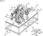
- Reel installation and removal device 30 is provided with reel set base 35, control device 39, feeder set unit 40, cover opening and closing unit 50, reel transfer unit 60, drum set unit 70, and tape cutting unit 90, which are provided on base plate 31.
- reel set base 35 is provided with base 36 and support pin 37.
- Base 36 is a plate-like member fixed so as to be erected vertically on upper plate 32 of base plate 31.
- Support pin 37 is a shaft-shaped member that is vertically erected from a plate surface on the right side in the drawing of base 36 and can be inserted into a center hole of reel 120.
- reel 120 is set to be installed and removed by reel transfer robot 24 or reel transfer unit 60 so that the center hole of reel 120 is inserted into support pin 37.
- feeder 100 as the installation and removal target of reel 120 is transferred by loader 29 to base 40a fixed to upper plate 32 of base plate 31. Similar to the feeder base such as mounting device 16, base 40a is provided with a connector to which connector 108 of feeder 100 can be connected and a pin hole into which positioning pin 109 can be engaged. Therefore, control device 39 can communicate with the control section of feeder 100 attached to feeder set unit 40 via the connection of the connector to control tape feeding section 102.
- feeder set unit 40 is provided with guide opening and closing section 42, tape drawing section 44, and tape splicing section 46.
- guide opening and closing section 42 is provided with a clamp that grips tape guide 104 from the left-right direction, an opening and closing cylinder that opens and closes the clamp, and a lifting and lowering cylinder that lifts and lowers the clamp, and lifts and lowers tape guide 104 by the clamp while gripping tape guide 104 from the left-right direction.
- Tape drawing section 44 is provided with a clip for grasping a distal end of cover tape 134 of reel 120 attached to feeder 100, a moving section for moving the clip, and an actuator for opening and closing the clip via a wire connected to the clip.
- Tape drawing section 44 causes the clip to enter tape guide 104 in a state where tape guide 104 is positioned upward by guide opening and closing section 42, and draws out cover tape 134 by grasping the distal end of cover tape 134 and retracting the clip.
- Fig. 7 is a schematic configuration diagram of tape splicing section 46.
- Tape splicing section 46 is provided with fixed clamp section 47, moving clamp section 48, and slide section 49.
- Fixed clamp section 47 is provided with a pair of clamp members 47a and 47b for clamping fixing piece 117 of splicing tape 116, and clamp cylinder 47c for performing clamping and releasing of the clamp by lifting and lowering clamp member 47a.
- Moving clamp section 48 is provided with a pair of clamp members 48a and 48b for clamping slide piece 119 of splicing tape 116, and clamp cylinder 48c for performing clamping and releasing of the clamp by lifting and lowering clamp member 48a.
- Slide section 49 is provided with slide block 49a coupled to clamp cylinder 48c of moving clamp section 48, and slide cylinder 49b that slides moving clamp section 48 together with slide block 49a.
- tape splicing section 46 is in a state where fixed clamp section 47 clamps fixed piece 117 and moving clamp section 48 clamps slide piece 119.
- feeder set unit 40 causes the distal end of cover tape 134 drawn out by tape drawing section 44 to be inserted into loop 118.
- moving clamp section 48 is moved to a distal end portion side of loop 118 by the operation of slide cylinder 49b to contract loop 118, so that tape splicing section 46 is coupled to loop 118 so that cover tape 134 does not come off.
- splicing tape 116 and cover tape 134 are spliced to each other (refer to Fig. 8 ).
- cover opening and closing unit 50 is provided with base 50a, support column 52, pivot plate 53, pickup platen 54, motor 55, and pulley 56.
- opening 32a (refer to Fig. 4 ) is formed in upper plate 32 of base plate 31 on the front surface side (on the right side) of feeder set unit 40.
- Cover opening and closing unit 50 is disposed below upper plate 32 by fixing four support columns 52 erected at four corners of rectangular flat base 50a to edges of opening 32a.
- Pivot plate 53 is formed in a substantially T-shape, a proximal end portion is supported by base 50a so as to be pivoted, and pickup platens 54 are attached to both ends of a distal end portion.
- Motor 55 is attached to base 50a, transmits a driving force via pulley 56, and pivots pivot plate 53.
- Pickup platen 54 is connected to a negative pressure source such as a vacuum pump via a tube, for example, and switches the presence or absence of pickup according to the presence or absence of operation of the vacuum pump.
- cover opening and closing unit 50 when pivot plate 53 is pivoted by the forward rotation of motor 55 until pivot plate 53 is substantially orthogonal to base 50a, pickup platen 54 abuts on reel cover 106 of feeder 100. In this state, cover opening and closing unit 50 can open reel cover 106 so as to be accommodated in opening 32a by picking up reel cover 106 on pickup platen 54 by the operation of the vacuum pump, and then pivoting pivot plate 53 by rotating motor 55 in the reverse direction.
- reel transfer unit 60 is provided with slide base 60a, support pin 61, expanding cylinder 61a, motor 62, push-in plate 63, push-in cylinder 63a, chuck 64, chuck cylinder 64a, guide pin 65, cutter 66, and cutter cylinder 66a.
- Slide base 60a is slidable in the X-axis direction and the Y-axis direction by slide unit 33 disposed on upper plate 32.
- Slide unit 33 includes a well-known configuration including a slide rail laid in the sliding direction, a slider or the like that slides along the slide rail by the driving of an actuator such as a motor.
- Support pin 61 is, for example, a pin configured in a cylindrical shape by combining two semi-cylindrical members having a semicircular cross-section, and can be inserted into the center hole of reel 120 in a cylindrical state.
- support pin 61 fits into the center hole of reel 120 and holds reel 120 so as not to fall off.
- Support pin 61 rotates around the shaft by transmitting the driving force of motor 62 via a pulley (not illustrated).
- Push-in plate 63 is a plate-like member formed so as to notch a location where support pin 61 is disposed, and moves along the extending direction of support pin 61 by the operation of push-in cylinder 63a to push and attach reel 120 to feeder 100 or the like.
- Chuck 64 holds a distal end of tape 130 of reel 120 by the operation of chuck cylinder 64a.
- Guide pin 65 guides the distal end of tape 130 of reel 120 toward chuck 64 side.
- Cutter 66 cuts the distal end of tape 130 by the operation of cutter cylinder 66a.
- push-turning disc 67 illustrated in Fig. 11 is configured to be installed and removed from support pin 61.
- Push-turning disc 67 is a disc-shaped member used when pushing and turning reel 120 so that support pin 61 in the cylindrical state can be inserted into the center hole, and multiple buffer members 68 are provided on the disc surface.
- Buffer member 68 is a rectangular parallelepiped-shaped member formed of, for example, urethane rubber or sponge, and is provided so that a longitudinal direction extends in a radial direction.
- a storage location of push-turning disc 67 is provided at a predetermined position of upper plate 32, and reel transfer unit 60 can move to the storage location to attach push-turning disc 67 to support pin 61 or detach push-turning disc 67 from support pin 61.
- drum set unit 70 is provided with fixed unit 71 including fixed base 71a fixed so as to be erected on upper plate 32, and moving unit 81 including slide base 81a slidable in the X-axis direction and the Y-axis direction by slide unit 34 disposed on upper plate 32.
- fixed unit 71 is provided with Y-axis slider 72, motor 73 (refer to Fig. 6 ), pulley 74, Z-axis slider 75, motor 76, pulley 77, chuck 78, and chuck cylinder 78a.
- Y-axis slider 72 moves a front surface (right surface in Fig.
- Z-axis slider 75 is provided on Y-axis slider 72, and moves in the Z-axis direction (up-down direction) along the front surface of Y-axis slider 72 by transmitting the driving force of motor 76 via pulley 77.
- Chuck 78 is provided on Z-axis slider 75, and holds splicing tape 116 of collecting drum 115 by the operation of chuck cylinder 78a.
- moving unit 81 is provided with rotary transfer disc 82, motor 83, drum chuck 84, chuck cylinder 84a (refer to Fig. 6 ), guide pin 85, pin cylinder 85a (refer to Fig. 6 ), tape chuck 86, chuck cylinder 86a, motor 87, and pulley 88.
- Rotary transfer disc 82 is a disc-shaped member including support shaft 82a to which drum main body 115a of collecting drum 115 is attached to be installed and removed, and can rotate drum main body 115a by being rotated by the driving of motor 83.
- rotary transfer disc 82 is formed with multiple long holes 82b (for example, three) extending in the radial direction at equal intervals in the circumferential direction.
- Drum chuck 84 is provided with multiple (three) chuck claws that move in long hole 82b by the operation of chuck cylinder 84a, and each chuck claw is opened and closed by the operation of chuck cylinder 84a to grasp or release collecting drum 115.
- Multiple guide pins 85 are provided so as to be erected from the left surface of moving unit 81 to fixed unit 71 side.
- Multiple guide pins 85 are provided at least at positions corresponding to each of guide pins 113 so that a path similar to the guide path for guiding cover tape 134 to collecting drum 115 can be formed in feeder 100.
- drum set unit 70 can guide guide pin 85 so that splicing tape 116 crawls on guide pin 85 to form a path similar to the guide path in feeder 100.
- a part of guide pin 85 is moved by the driving of pin cylinder 85a, so that splicing tape 116 can be held by guide pins 85.
- Tape chuck 86 can hold the distal end of splicing tape 116 forming the guide path by the operation of chuck cylinder 86a, and the distal end position of held splicing tape 116 can be adjusted by transmitting the driving force of motor 87 via pulley 88 and moving in the Y-axis direction.
- tape cutting unit 90 is provided with base 90a, cutting base 91, tape feeding section 92, first tape cutter 95, second tape cutter 96, third tape cutter 97, and slider 98.
- Tape feeding section 92 is provided with sprocket 93 having a protrusion formed on an outer periphery for engaging with an engagement hole of tape 130, and motor 94 for driving sprocket 93.
- tape feeding section 92 rotates sprocket 93 by the forward rotation of motor 94 to feed tape 130 toward the cutting position.
- First tape cutter 95 has a scissor-shaped cutting blade disposed in a direction orthogonal to the feeding direction of tape 130, and is operated by the driving of cutter cylinder 95a to cut tape 130.
- second tape cutter 96 a cutting blade is disposed obliquely with respect to the feeding direction of tape 130, and the right side of the distal end of tape 130 is cut in a tapered manner by the driving of cutter cylinder 96a.
- third tape cutter 97 a cutting blade is disposed obliquely with respect to the feeding direction of tape 130, and the left side of the distal end of tape 130 is cut in a tapered manner by the driving of cutter cylinder 97a.
- Third tape cutter 97 is provided on slider 98 that slides in the X-axis direction (left-right direction) above cutting base 91, and is movable in the left-right direction. Therefore, by adjusting the position of third tape cutter 97 in accordance with the width of tape 130, tape cutting unit 90 can cut in a tapered manner the left side of the distal end of tape 130 fed out with reference to the right end of cutting base 91. By cutting the distal end of tape 130 (cover tape 134) in a tapered manner, it is possible to prevent the distal end from being caught when inserting tape 130 into loop 118, so that tape 130 can be smoothly inserted (refer to Fig. 7 ).
- Control device 39 is provided with CPU 39a, ROM 39b, RAM 39c, and the like. Status information and the like are inputted from each unit of reel installation and removal device 30, and status information on reel transfer robot 24 and loader 29, instruction for installation and removal of reel 120, and the like are inputted from management device 2 to control device 39. Control device 39 outputs a control signal to each unit of reel installation and removal device 30 based on the information and the instruction for installation and removal to install and remove reel 120 to and from feeder 100 set in feeder set unit 40. In addition to these configurations, reel installation and removal device 30 may be provided with a camera capable of capturing an image of label 122 of reel 120 attached to feeder 100.
- a temporary fastening portion for fastening tape 130 with a temporary fastening tape may be provided, or a peeling portion for peeling the temporary fastening tape when reel 120 is attached may be provided.
- Fig. 17 is a flowchart illustrating an example of a reel detachment process.
- the process is executed by control device 39 in a case where feeder 100 as a detachment target from reel 120 is set in feeder set unit 40.
- control device 39 causes cover opening and closing unit 50 so as to open reel cover 106 (S100).
- cover opening and closing unit 50 holds reel cover 106 in opening 32a, reel cover 106 in the opened state can be prevented from interfering with the movement or operation of other units.
- control device 39 controls slide unit 33 so that reel transfer unit 60 moves to feeder set unit 40 (S105).
- Reel transfer unit 60 is in a state where push-turning disc 67 is attached to support pin 61. Subsequently, control device 39 causes feeder 100 and reel transfer unit 60 set in feeder set unit 40 so as to reserve a predetermined length to rewind tape 130 (S110). In S110, control device 39 causes tape feeding section 102 of feeder 100 so as to rotate in the reverse direction, and controls reel transfer unit 60 so as to push and turn reel 120 in the reverse rotation direction by push-turning disc 67. When S110 is ended, control device 39 causes reel transfer unit 60 so as to detach push-turning disc 67 from support pin 61.
- first type feeder 100 using collecting drum 115 since a distal end of cover tape 134 is spliced to splicing tape 116 when reel 120 is attached (refer to Fig. 8 ) next time, the length of tape 130 (cover tape 134) that needs to be reserved when reel 120 is detached may be shortened.
- second type feeder 100 or the like using a take-up gear it is necessary to reserve a length necessary for cover tape 134 to reach the take-up gear when reel 120 is attached next time.
- a predetermined length is reserved according to the type requiring the longest length (here, second type) so that reel 120 can handle any type of feeder 100 to be attached next time.
- control device 39 causes reel transfer unit 60 so as to cut tape 130 to detach reel 120 from feeder 100 (S115).
- Reel transfer unit 60 cuts tape 130 by causing cutter 66 to enter feeder 100.
- control device 39 controls slide unit 33 so that reel transfer unit 60 moves to reel set base 35 (S120), and causes reel transfer unit 60 so as to set detached reel 120 on reel set base 35 (S125).
- reel 120 set on reel set base 35 is transferred to cradle 22a of automatic reel storage 22 by reel transfer robot 24.
- reel 120 having no remaining components is transferred to used reel storage location 25 by reel transfer robot 24, or is discharged from a discharge port (not illustrated) formed in upper plate 32.
- control device 39 determines whether feeder 100 is the first type using collecting drum 115 (S130). When it is determined that the type is the first type, control device 39 controls slide unit 34 so that moving unit 81 of drum set unit 70 moves to feeder set unit 40 (S135). Next, control device 39 causes drum chuck 84 of moving unit 81 so as to detach collecting drum 115 from feeder 100 (S140). Control device 39 controls slide unit 34 so that moving unit 81 moves to a standby position in front of fixed unit 71 or the like (S145). When it is determined in S130 that the type is not the first type, control device 39 skips S135 to S145.
- Collecting drum 115 detached in S140 is assumed to be collected in a dust box or the like from a discharge port (not illustrated) formed in upper plate 32 until moving unit 81 moves to the standby position.
- the operator may detach cover tape 134 from collecting drum 115 collected in the dust box, discard cover tape 134, and set collecting drum 115 at a predetermined location where moving unit 81 of drum set unit 70 can receive collecting drum 115.
- Control device 39 determines whether reel 120 is attached to feeder 100 set in feeder set unit 40 (S150). When it is determined that reel 120 is not to be attached, control device 39 causes cover opening and closing unit 50 so as to close reel cover 106 (S155), and ends the reel detachment process. On the other hand, when it is determined that reel 120 is attached, control device 39 skips S155, and ends the reel detachment process while maintaining reel cover 106 open.
- Fig. 18 is a flowchart illustrating an example of the reel attachment process.
- the process is executed by control device 39 in a case where feeder 100 as an attachment target to reel 120 is set in feeder set unit 40, for example, in a case where the reel detachment process in Fig. 17 ends with reel cover 106 open, or the like.
- control device 39 controls slide unit 33 so that reel transfer unit 60 moves to reel set base 35 (S200).
- Reel transfer unit 60 is in a state where push-turning disc 67 is detached from support pin 61.
- control device 39 causes reel transfer unit 60 to receive reel 120 set on reel set base 35 (S205).
- control device 39 controls slide unit 33 so that reel transfer unit 60 moves to tape cutting unit 90 (S210).
- Reel transfer unit 60 and tape cutting unit 90 are controlled so that a necessary amount of tape 130 is fed from reel 120 to cut the distal end of tape 130 into a necessary shape (S215).
- control device 39 causes tape cutting unit 90 so as to cut in a tapered manner the distal end of tape 130 in order to be easily inserted into loop 118 as described above.
- control device 39 causes tape cutting unit 90 so as to cut only in a direction orthogonal to the longitudinal direction of tape 130, for example. The distal ends of all tapes 130 may be cut in a tapered manner.
- control device 39 causes reel transfer unit 60 so as to rewind tape 130 and hold the distal end of tape 130 by chuck 64.
- control device 39 controls slide unit 33 so that reel transfer unit 60 moves to feeder set unit 40 (S220).
- control device 39 causes cover opening and closing unit 50 so as to open reel cover 106 before S220.
- control device 39 causes reel transfer unit 60 and slide unit 33 so as to attach reel 120 to feeder 100 set in feeder set unit 40, and move to a predetermined standby position (S225).
- Control device 39 determines whether feeder 100 is the required first type of collecting drum 115 (S230). When it is determined that the tape is the first type, control device 39 causes drum set unit 70 so as to cause splicing tape 116 to crawl along the path formed by guide pins 85, to hold splicing tape 116 by guide pins 85, and to grasp and hold the distal end of splicing tape 116 by tape chuck 86 (S235). Next, control device 39 controls slide unit 34 so that moving unit 81 moves to feeder set unit 40 (S240). Subsequently, control device 39 causes drum set unit 70 so as to attach collecting drum 115 and splicing tape 116 to feeder 100 of feeder set unit 40 (S245).
- Control device 39 attaches splicing tape 116 crawled along the path formed by guide pin 85 so as to pass splicing tape 116 to each guide pin 113 of feeder 100 in that state, and then causes drum set unit 70 so as to release the holding of splicing tape 116 by guide pins 85. As a result, splicing tape 116 can be attached along the guide path of feeder 100.
- control device 39 skips S235 to S245. Control device 39 may execute S235 to S245 before S200 to S215, or may execute S235 to S245 in parallel with S200 to S215.
- Control device 39 causes feeder set unit 40 so as to perform a distal end process of tape 130 (S250). For example, when feeder 100 is the first type, control device 39 causes feeder set unit 40 so as to draw cover tape 134 and splice cover tape 134 to splicing tape 116. In addition, when feeder 100 is the second type, control device 39 causes feeder set unit 40 so as to draw cover tape 134 and feed to the guide path. When reel 120 is attached in this manner, control device 39 causes cover opening and closing unit 50 so as to close reel cover 106 (S255), and ends the reel attachment process.
- control device 39 may cause the camera to capture an image of label 122 before closing reel cover 106, and may perform image processing on the captured image to recognize the information on label 122. Based on the recognized information, control device 39 may confirm whether correct reel 120 is attached, register the attachment in association with feeder 100, or transmit the recognized information to management device 2 together with the notification that the attachment of reel 120 is completed.
- Reel installation and removal device 30 of the present embodiment corresponds to the reel installation and removal device of the present disclosure
- feeder set unit 40 corresponds to a feeder set unit
- reel transfer unit 60 corresponds to a reel transfer unit
- chuck 64 corresponds to a holding section
- cutter 66 corresponds to a cutting section
- control device 39 corresponds to a control device.
- Collecting drum 115 corresponds to a drum-shaped collecting section.
- Guide pin 85 corresponds to a path forming section
- chuck 78, Y-axis slider 72, and Z-axis slider 75 correspond to a guide section
- drum set unit 70 corresponds to a collecting section set unit
- tape splicing section 46 corresponds to a splicing section.
- Reel cover 106 corresponds to an opening and closing cover
- cover opening and closing unit 50 corresponds to a cover opening and closing unit.
- preparation line 20 corresponds to a feeder preparation system
- feeder storage 26 corresponds to a feeder storage section
- loader 29 corresponds to a feeder preparation device
- reel set base 35 corresponds to a reel set base
- reel transfer robot 24 corresponds to a reel preparation device.
- reel transfer unit 60 rotates push-turning disc 67, so that tape 130 can be appropriately rewound on reel 120.
- tape 130 is rewound to a portion to which the component has been supplied and cut, so that it is possible to prevent the component from falling off by the distal end process of tape 130 when reel 120 is attached next time. As a result, reel 120 can be more appropriately detached.
- tape 130 (cover tape 134) is rewound so as to reserve a predetermined length, it is possible to suppress the time required for the process to collect cover tape 134 when reel 120 is attached next time.
- drum set unit 70 can efficiently attach collecting drum 115.
- reel installation and removal device 30 can be configured to be more compact than those performed by separate devices.
- cover opening and closing unit 50 can further efficiently detach and attach the reel.
- tape 130 is rewound by reserving a predetermined length when reel 120 is detached; however, the configuration is not limited to this, and, for example, an extension tape having a necessary length may be added to the distal end of tape 130 when reel 120 is attached next time.
- both chuck 64 and cutter 66 are provided in reel transfer unit 60; however, the configuration is not limited to this, either or both may be provided in a place other than reel transfer unit 60, and, for example, may be provided in feeder set unit 40.
- first type feeder 100 to be collected by collecting drum 115 is exemplified, and drum set unit 70 that installs and removes collecting drum 115 and forms the path of splicing tape 116 is provided; however, the configuration is not limited to this.
- reel transfer unit 60 may detach collecting drum 115 together with reel 120 instead of drum set unit 70.
- the path formation of splicing tape 116 may be performed by feeder set unit 40 or reel transfer unit 60 after collecting drum 115 is attached to feeder 100. In such a case or in a case where first type feeder 100 is not handled, drum set unit 70 need not be provided.
- reel cover 106 is attached to the lower edge of feeder 100 in an openable and closable manner; however, the configuration is not limited to this, reel cover 106 may be attached to feeder 100 in an openable and closable manner, and the opening and closing direction may be the left-right direction.
- feeder 100 is set such that feeder set unit 40 can drive tape feeding section 102; however, the configuration is not limited to this, and feeder 100 may be set such that tape feeding section 102 cannot be driven.
- reel transfer unit 60 is configured to push and turn reel 120 by using push-turning disc 67, reel 120 may be rotated by a method other than push-turning.
- reel transfer unit 60 may not rotate reel 120 (may not include a rotation section).
- control device 39 may be driven at least chuck 64 (holding section) and cutter 66 (cutting section) so as to hold and cut tape 130 at the portion to which the component has been supplied, in a state where feeder 100 to which reel 120 is attached is set in feeder set unit 40.
- preparation line 20 including loader 29 for setting feeder 100 in feeder set unit 40, reel transfer robot 24 for setting reel 120 in reel set base 35, and the like is exemplified; however, the configuration is not limited to this.
- Reel installation and removal device 30 is individually disposed, and the set of feeder 100 and the set of reel 120 may be performed by another device such as AGV, or may be performed by an operator.
- the disposition of each unit of reel installation and removal device 30 and the function of each unit are examples, and reel installation and removal device 30 as a whole may be configured to automatically install and remove reel 120 with respect to feeder 100.
- the reel installation and removal device of the present disclosure may be configured as follows.
- the tape may include a bottom tape accommodating the component and a cover tape covering the component, and may be capable of supplying the component by peeling off the cover tape, as the feeder, multiple types of feeders including a type having a drum-shaped collecting section collecting the cover tape while winding the cover tape together with a splicing tape to which a distal end is spliced to the cover tape and a type in which the cover tape is pulled and collected to the collecting section different from the drum shape may be provided, and the control device may drive the driving section and the rotation section to rewind the cover tape by reserving a length adaptable for any type when the reel is attached to the feeder next time in the detachment control. Accordingly, it is possible to appropriately detach the reel in consideration of the case where the reel is attached next time. Therefore, it is possible to efficiently perform the automatic attachment of the reel while suppressing the time required for the process to collect the cover tape
- the feeder may be provided with a guide path guiding the cover tape to the collecting section
- the device further may include a collecting section set unit configured to be moved relative to the feeder set unit, having a path forming section forming a path along the guide path and a guide section guiding the splicing tape to crawl on the path forming section, and configured to transfer the drum-shaped collecting section
- the feeder set unit may include a splicing section configured to splice a distal end of the splicing tape and a distal end of the peeled cover tape
- the control device may cause the collecting section set unit so as to attach the splicing tape and the collecting section to the feeder set in the feeder set unit, and may control the feeder set unit so that the splicing section splices the distal end of the splicing tape and the distal end of the cover tape, after the splicing tape is crawled on the path forming section in advance in the collecting section set unit.
- the control device may execute an attachment control of attaching the reel to the feeder in a state where the feeder from which the reel is detached is set in the feeder set unit, driving the holding section and the rotation section so that a distal end of the tape is fed from the reel to the feeding section, and controlling the feeder set unit and the reel transfer unit so that the feeding section is driven until the distal end of the tape reaches a predetermined position. Accordingly, since the detachment and the attachment of the reels can be performed by a common installation and removal device, the installation and removal device can be configured to be compact.
- the feeder may include an opening and closing cover that exposes the reel in an opened state to be installed and removed
- the device further includes a cover opening and closing unit configured to open and close the opening and closing cover of the feeder set in the feeder set unit, and to hold the opening and closing cover in the opened state at a position not interfering with a relative movement of other units to the feeder set unit. Accordingly, the installation and removal of the reel can be further efficiently performed.
- another reel installation and removal device of the present disclosure is a reel installation and removal device that installs and removes a reel on which a tape accommodating a component is wound to and from a feeder which feeds the tape by driving of a feeding section and supplies the component, the device including a feeder set unit on which the feeder is set, a holding section configured to hold the tape of the reel mounted on the feeder, a cutting section configured to cut the tape, and a control device configured to drive the holding section and the cutting section so that the tape is held and cut at a portion to which the component has been supplied, in a state where the feeder to which the reel is attached is set in the feeder set unit.
- a feeder preparation system of the present disclosure includes any of the reel installation and removal devices described above, a feeder preparation device configured to transfer the feeder between a feeder storage section storing multiple feeders and the feeder set unit, and to prepare the feeder as an installation and removal target of the reel, a reel set base on which the reel is set so that the reel transfer unit is transferred, and a reel preparation device configured to transfer the reel between a reel storage section storing multiple reels and the reel set base, and to prepare the reel as an installation and removal target to the feeder.
- the reel is automatically installed and removed to and from the feeder by any of the reel installation and removal devices described above, it is possible to more appropriately detach the reel.
- the preparation of the feeder and the preparation of the reel can also be automatically performed, the automatic installation and removal of the reel can be further efficiently performed.
- the present disclosure can be used in the manufacturing industry of component mounting systems and the like.
- 1 component mounting system 2 management device, 4 AGV, 10 mounting line, 12 printing device, 14 printing inspection device, 16 mounting device, 18 feeder storage location, 19 loader, 20 preparation line, 22 automatic reel storage, 22a cradle, 24 reel transfer robot, 25 reel storage location, 26 feeder storage, 28 feeder storage location, 29 loader, 30 reel installation and removal device, 31 base plate, 32 upper plate, 32a opening, 33, 34 slide unit, 35 reel set base, 36 base, 37 support pin, 39 control device, 39a CPU, 39b ROM, 39c RAM, 40 feeder set unit, 40a base, 42 guide opening and closing section, 44 tape drawing section, 46 tape splicing section, 47 fixed clamp section, 47a, 47b, 48a, 48b clamp member, 47c, 48c clamp cylinder, 48 moving clamp section, 49 slide section, 49a slide block, 49b slide cylinder, 50 cover opening and closing unit, 50a base, 52 support column, 53 pivot plate, 54 pickup platen, 55 motor, 56 pulley, 60 reel transfer unit, 60a slide base, 61 support pin
Landscapes
- Engineering & Computer Science (AREA)
- Manufacturing & Machinery (AREA)
- Microelectronics & Electronic Packaging (AREA)
- Supply And Installment Of Electrical Components (AREA)
Abstract
Description
- The present specification discloses a reel installation and removal device and a feeder preparation system.
- Conventionally, there has been proposed a method of automatically installing and removing a reel on which a tape accommodating components is wound from a feeder. For example,
Patent Literature 1 discloses that a reel detached from a feeder is received in a reel storage, or a reel delivered from the reel storage is attached to the feeder. As a result, it is assumed that an exchange operation of the reel can be performed without bothering the operator. - Patent Literature 1:
JP-A-2014-197594 - It can be said that promoting the automation of the exchange operation of the reel as described above can be regarded as an important issue for improving production efficiency. Here, since the number of feeders to which the reels are attached is limited and the feeders are often reused, it is necessary to first detach the reels attached to the feeders when a new reel is attached. At this time, it is necessary to appropriately process and detach the tape so that the efficiency when automatically attaching the detached reel next time is not reduced.
- The main object of the present disclosure is to more appropriately detach a reel in a case where the reel is automatically installed and removed.
- The present disclosure adopts the following means in order to achieve the above-described main object.
- It is a gist that a reel installation and removal device of the present disclosure is a reel installation and removal device that installs and removes a reel on which a tape accommodating a component is wound to and from a feeder which feeds the tape by driving of a feeding section and supplies the component, the device including a feeder set unit on which the feeder is set so that the feeding section is driven, a reel transfer unit including a rotation section rotating the reel around a shaft, and configured to move relative to the feeder set unit to transfer the reel, a holding section configured to hold the tape of the reel mounted on the feeder, a cutting section configured to cut the tape, and a control device configured to execute a detachment control of driving the holding section and the cutting section so that the tape is held and cut in a portion to which the component has been supplied after driving the feeding section and the rotation section so that the tape is rewound and wound around the reel, and controlling the feeder set unit and the reel transfer unit so as to detach the reel from the feeder, in a state where the feeder to which the reel is attached is set in the feeder set unit.
- In the reel installation and removal device of the present disclosure, since the feeder is set on the feeder set unit so as to be able to drive the feeding section of the tape, the tape can be rewound quickly when the reel is detached. In addition, the tape can be appropriately rewound on the reel by the rotation section of the reel transfer unit. In addition, by rewinding and cutting the tape to a portion to which the component has been supplied, it is possible to prevent the component from being affected by a distal end process of the tape when attaching the reel next time. As a result, the reel can be more appropriately detached.
-
- [
Fig. 1] Fig. 1 is a schematic configuration diagram ofcomponent mounting system 1. - [
Fig. 2] Fig. 2 is a schematic configuration diagram offeeder 100. - [
Fig. 3] Fig. 3 is a schematic configuration diagram of collectingdrum 115. - [
Fig. 4] Fig. 4 is a layout diagram illustrating a layout of a part of a configuration ofpreparation line 20. - [
Fig. 5] Fig. 5 is a schematic configuration diagram of reel installation andremoval device 30. - [
Fig. 6] Fig. 6 is a block diagram illustrating an electrical connection relationship of reel installation andremoval device 30. - [
Fig. 7] Fig. 7 is a schematic configuration diagram oftape splicing section 46. - [
Fig. 8] Fig. 8 is an explanatory diagram of a state wheresplicing tape 116 andcover tape 134 are spliced. - [
Fig. 9] Fig. 9 is a schematic configuration diagram of cover opening andclosing unit 50. - [
Fig. 10] Fig. 10 is a schematic configuration diagram ofreel transfer unit 60. - [
Fig. 11] Fig. 11 is a schematic configuration diagram of push-turningdisc 67 attached toreel transfer unit 60. - [
Fig. 12] Fig. 12 is a schematic configuration diagram ofdrum set unit 70. - [
Fig. 13] Fig. 13 is a schematic configuration diagram offixed unit 71. - [
Fig. 14] Fig. 14 is a schematic configuration diagram of movingunit 81. - [
Fig. 15] Fig. 15 is a schematic configuration diagram oftape cutting unit 90. - [
Fig. 16] Fig. 16 is an enlarged configuration diagram oftape cutting unit 90. - [
Fig. 17] Fig. 17 is a flowchart illustrating an example of a reel detachment process. - [
Fig. 18] Fig. 18 is a flowchart illustrating an example of a reel attachment process. - Next, embodiments of the present disclosure will be described with reference to the drawings.
Fig. 1 is a schematic configuration diagram ofcomponent mounting system 1 of the present embodiment.Component mounting system 1 is provided withmounting line 10 for mounting a component on a board,preparation line 20 for preparing the supply of the component, andmanagement device 2 for managing the entire system, and these lines and device are installed in a factory or the like.Management device 2 is configured as a computer including CPU, ROM, RAM, and HDD (not illustrated), outputs information and instructions related to mounting to each device ofmounting line 10, and outputs information and instructions related to preparation to each device ofpreparation line 20. In the present embodiment, a left-right direction (X-axis), a front-rear direction (Y-axis), and an up-down direction (Z-axis) are as illustrated inFig. 1 . - As illustrated in
Fig. 1 ,mounting line 10 is provided withprinting device 12 for printing solder on the board,printing inspection device 14 for inspecting the state of the printed solder, and mountingdevice 16 for mounting the component on the board.Multiple mounting devices 16 are installed side by side along the conveyance direction of the board (X-axis direction), andmultiple feeders 100 for supplying components can be mounted on a front surface. Eachmounting device 16 is configured to pick up the component supplied from mountedfeeder 100 and mount the component on the board. In addition,mounting line 10 is provided withfeeder storage location 18 installed betweenmounting device 16 andprinting inspection device 14 on the most upstream side in the conveyance direction of the board amongmultiple mounting devices 16, andloader 19 that moves front ofmultiple mounting devices 16 and front offeeder storage location 18 along the conveyance direction of the board. Automated guided vehicle (AGV) 4 or the operator accommodatesfeeder 100 necessary forfeeder storage location 18, and collectsunnecessary feeder 100 fromfeeder storage location 18. In addition,loader 19 is configured to take outnecessary feeder 100 fromfeeder storage location 18 and providefeeder 100 to mountingdevice 16, or to collectunnecessary feeder 100 from eachmounting device 16 and returnfeeder 100 tofeeder storage location 18.Mounting line 10 may be provided with a reflow device or the like that performs a reflow process of the board on which the component is mounted. - Here,
Fig. 2 is a schematic configuration diagram offeeder 100. Infeeder 100,reel 120 on whichtape 130 accommodating the component is wound is attached to be installed and removed to main body 101, and the component is supplied byfeeding tape 130. Label 122 that indicates the ID ofreel 120, information on the component type accommodated bytape 130, and the like is attached toreel 120.Tape 130 is configured to include bottom tape 132 in which multiple cavities (recessed portions) are formed at predetermined intervals in the longitudinal direction and components are accommodated in each cavity, andcover tape 134 that is adhered so as to cover the surface of bottom tape 132. Engagement holes are formed intape 130 at equal intervals in the longitudinal direction. -
Feeder 100 is provided with main body 101, tape feeding section 102, tape guide 104, reel cover 106, connector 108, positioning pin 109, tape collecting section 110, and control section (not illustrated). - Tape feeding section 102 is provided with a sprocket in which a protrusion is provided on an outer periphery for engaging with an engagement hole of
tape 130, and motor 103 (refer toFig. 6 ) for driving the sprocket. In a state wheretape 130 is engaged with the sprocket, tape feeding section 102 intermittently rotates the sprocket by the forward rotation of the motor to pitch-feed tape 130 to the supply position of the component. In addition, tape feeding section 102 can rewindtape 130 towardreel 120 side by the reverse rotation of the motor. Tape guide 104 is provided on the upper portion of main body 101 to guidecover tape 134 peeled fromtape 130 so as to be folded back toward tape collecting section 110, and to guide the bottom tape from whichcover tape 134 is peeled to the supply position of the component. Tape guide 104 is configured to be able to slightly move up and down (open and close) with respect to main body 101. Reel cover 106 is provided at a lower edge portion of main body 101 in an openable and closable manner, coversreel 120 in a closed state so as not to fall off, and exposesreel 120 in an opened state (state inFig. 2 ) to be installed and removed. Connector 108 and positioning pin 109 are provided so as to protrude from an end surface of main body 101. Although not illustrated, a connector to which connector 108 can be connected and a pin hole into which positioning pin 109 can be engaged are provided on a feeder base such as mountingdevice 16 andfeeder storage location 18. Therefore, whenfeeder 100 is mounted on the feeder base, connector 108 is connected to the connector of the feeder base and positioning pin 109 engages with the pin hole. The control section (not illustrated) offeeder 100 can communicate with a control section or the like of mountingdevice 16 via the connector, and controls tape feeding section 102 so as to pitch-feed tape 130 in response to a component supply instruction. - Tape collecting section 110 collects
cover tape 134 peeled fromtape 130, and as an example, a type (first type) in which covertape 134 is collected while being wound using collectingdrum 115 is illustrated. Tape collecting section 110 is provided with drum shaft 111 to whichannular collecting drum 115 is attached to be installed and removed and rotated by a motor (not illustrated), and multiple guide pins 113 forming a guide path for guidingcover tape 134 folded back by tape guide 104 to collectingdrum 115.Fig. 3 is a schematic configuration diagram of collectingdrum 115, and collectingdrum 115 is provided withsplicing tape 116 extending from annular drummain body 115a.Splicing tape 116 is provided with fixingpiece 117 fixed to a distal end,U-shaped loop 118 having both proximal end portions attached to an end surface of fixingpiece 117, andslide piece 119 slidably attached along an extending direction of loop 118 (arrow direction inFig. 3 ). As will be described later,loop 118 ofsplicing tape 116 is spliced to covertape 134 by the sliding ofslide piece 119. Tape collecting section 110 winds up and collectscover tape 134 together with splicingtape 116 by rotating drum shaft 111 to which collectingdrum 115 is attached by the driving of the motor. In addition, for example, there is a type (second type) in which covertape 134 is pulled in and collected by rotating a pair of gears while gripingcover tape 134, but since the configuration is well known, a description thereof will be omitted. - As illustrated in
Figs. 1 and4 ,preparation line 20 is provided withautomatic reel storage 22,reel transfer robot 24,reel storage location 25,feeder storage 26,feeder storage location 28,loader 29, and reel installation andremoval device 30.Automatic reel storage 22 is configured to automatically storereel 120 placed oncradle 22a provided in front andstore reel 120 in the storage, or to automatically take outnecessary reel 120 from the storage andplace reel 120 oncradle 22a.Reel transfer robot 24 is provided with a vertical articulated robot arm.Reel transfer robot 24 transfers reel 120 placed inreel storage location 25 by the operator to cradle 22a ofautomatic reel storage 22, or transfers reel 120 discharged tocradle 22a into reel installation andremoval device 30.AGV 4 or the operator returnsfeeder 100 collected from mountingline 10 tofeeder storage location 28, or takes outnecessary feeder 100 fromfeeder storage location 28 to accommodatefeeder 100 infeeder storage location 18 of mountingline 10.Loader 29 moves front ofmultiple feeder storages 26 and front offeeder storage location 28, takes outfeeder 100 fromfeeder storage location 28 to be accommodated infeeder storage 26, or takes outfeeder 100 fromfeeder storage 26 to be accommodated infeeder storage location 28. In addition,loader 29transfers feeder 100 as an installation and removal target ofreel 120 into reel installation andremoval device 30. InFig. 1 , asreel storage location 25, two storage locations of a storage location for used (component shortage)reel 120 and a storage location fornew reel 120 are exemplified. - Reel installation and
removal device 30 is provided with reel setbase 35,control device 39, feeder setunit 40, cover opening andclosing unit 50,reel transfer unit 60,drum set unit 70, andtape cutting unit 90, which are provided onbase plate 31. - As illustrated in
Fig. 5 , reel setbase 35 is provided withbase 36 andsupport pin 37.Base 36 is a plate-like member fixed so as to be erected vertically onupper plate 32 ofbase plate 31.Support pin 37 is a shaft-shaped member that is vertically erected from a plate surface on the right side in the drawing ofbase 36 and can be inserted into a center hole ofreel 120. On reel setbase 35,reel 120 is set to be installed and removed byreel transfer robot 24 orreel transfer unit 60 so that the center hole ofreel 120 is inserted intosupport pin 37. - In feeder set
unit 40,feeder 100 as the installation and removal target ofreel 120 is transferred byloader 29 tobase 40a fixed toupper plate 32 ofbase plate 31. Similar to the feeder base such as mountingdevice 16,base 40a is provided with a connector to which connector 108 offeeder 100 can be connected and a pin hole into which positioning pin 109 can be engaged. Therefore,control device 39 can communicate with the control section offeeder 100 attached to feeder setunit 40 via the connection of the connector to control tape feeding section 102. - In addition, as illustrated in
Fig. 6 , feeder setunit 40 is provided with guide opening andclosing section 42,tape drawing section 44, andtape splicing section 46. Although not illustrated, guide opening andclosing section 42 is provided with a clamp that grips tape guide 104 from the left-right direction, an opening and closing cylinder that opens and closes the clamp, and a lifting and lowering cylinder that lifts and lowers the clamp, and lifts and lowers tape guide 104 by the clamp while gripping tape guide 104 from the left-right direction.Tape drawing section 44 is provided with a clip for grasping a distal end ofcover tape 134 ofreel 120 attached tofeeder 100, a moving section for moving the clip, and an actuator for opening and closing the clip via a wire connected to the clip.Tape drawing section 44 causes the clip to enter tape guide 104 in a state where tape guide 104 is positioned upward by guide opening andclosing section 42, and draws outcover tape 134 by grasping the distal end ofcover tape 134 and retracting the clip. -
Fig. 7 is a schematic configuration diagram oftape splicing section 46.Tape splicing section 46 is provided with fixedclamp section 47, movingclamp section 48, andslide section 49.Fixed clamp section 47 is provided with a pair ofclamp members fixing piece 117 ofsplicing tape 116, and clampcylinder 47c for performing clamping and releasing of the clamp by lifting and loweringclamp member 47a. Movingclamp section 48 is provided with a pair ofclamp members slide piece 119 ofsplicing tape 116, and clampcylinder 48c for performing clamping and releasing of the clamp by lifting and loweringclamp member 48a.Slide section 49 is provided withslide block 49a coupled to clampcylinder 48c of movingclamp section 48, andslide cylinder 49b that slides movingclamp section 48 together withslide block 49a. As illustrated inFig. 7A ,tape splicing section 46 is in a state where fixedclamp section 47 clamps fixedpiece 117 and movingclamp section 48 clamps slidepiece 119. In this state, feeder setunit 40 causes the distal end ofcover tape 134 drawn out bytape drawing section 44 to be inserted intoloop 118. As illustrated inFig. 7B , movingclamp section 48 is moved to a distal end portion side ofloop 118 by the operation ofslide cylinder 49b to contractloop 118, so thattape splicing section 46 is coupled toloop 118 so thatcover tape 134 does not come off. In this manner, splicingtape 116 and covertape 134 are spliced to each other (refer toFig. 8 ). - As illustrated in
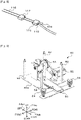
Fig. 9 , cover opening andclosing unit 50 is provided withbase 50a,support column 52,pivot plate 53,pickup platen 54,motor 55, andpulley 56. Here, opening 32a (refer toFig. 4 ) is formed inupper plate 32 ofbase plate 31 on the front surface side (on the right side) of feeder setunit 40. Cover opening andclosing unit 50 is disposed belowupper plate 32 by fixing foursupport columns 52 erected at four corners of rectangularflat base 50a to edges ofopening 32a.Pivot plate 53 is formed in a substantially T-shape, a proximal end portion is supported bybase 50a so as to be pivoted, andpickup platens 54 are attached to both ends of a distal end portion.Motor 55 is attached tobase 50a, transmits a driving force viapulley 56, and pivotspivot plate 53.Pickup platen 54 is connected to a negative pressure source such as a vacuum pump via a tube, for example, and switches the presence or absence of pickup according to the presence or absence of operation of the vacuum pump. In cover opening andclosing unit 50, whenpivot plate 53 is pivoted by the forward rotation ofmotor 55 untilpivot plate 53 is substantially orthogonal tobase 50a,pickup platen 54 abuts on reel cover 106 offeeder 100. In this state, cover opening andclosing unit 50 can open reel cover 106 so as to be accommodated inopening 32a by picking up reel cover 106 onpickup platen 54 by the operation of the vacuum pump, and then pivotingpivot plate 53 by rotatingmotor 55 in the reverse direction. - As illustrated in
Fig. 10 ,reel transfer unit 60 is provided withslide base 60a,support pin 61, expanding cylinder 61a,motor 62, push-inplate 63, push-incylinder 63a, chuck 64,chuck cylinder 64a,guide pin 65,cutter 66, andcutter cylinder 66a.Slide base 60a is slidable in the X-axis direction and the Y-axis direction byslide unit 33 disposed onupper plate 32.Slide unit 33 includes a well-known configuration including a slide rail laid in the sliding direction, a slider or the like that slides along the slide rail by the driving of an actuator such as a motor.Support pin 61 is, for example, a pin configured in a cylindrical shape by combining two semi-cylindrical members having a semicircular cross-section, and can be inserted into the center hole ofreel 120 in a cylindrical state. In addition, when the two semi-cylindrical members move in a direction away from each other due to the operation of expanding cylinder 61a and the outer diameter is expanded,support pin 61 fits into the center hole ofreel 120 and holds reel 120 so as not to fall off.Support pin 61 rotates around the shaft by transmitting the driving force ofmotor 62 via a pulley (not illustrated). Push-inplate 63 is a plate-like member formed so as to notch a location wheresupport pin 61 is disposed, and moves along the extending direction ofsupport pin 61 by the operation of push-incylinder 63a to push and attachreel 120 tofeeder 100 or the like.Chuck 64 holds a distal end oftape 130 ofreel 120 by the operation ofchuck cylinder 64a.Guide pin 65 guides the distal end oftape 130 ofreel 120 towardchuck 64 side.Cutter 66 cuts the distal end oftape 130 by the operation ofcutter cylinder 66a. - In addition, in
reel transfer unit 60, push-turning disc 67 illustrated inFig. 11 is configured to be installed and removed fromsupport pin 61. Push-turning disc 67 is a disc-shaped member used when pushing and turningreel 120 so thatsupport pin 61 in the cylindrical state can be inserted into the center hole, andmultiple buffer members 68 are provided on the disc surface.Buffer member 68 is a rectangular parallelepiped-shaped member formed of, for example, urethane rubber or sponge, and is provided so that a longitudinal direction extends in a radial direction. When the outer diameter ofsupport pin 61 is expanded by the operation of expanding cylinder 61a,support pin 61 fits into the center hole of push-turning disc 67 and can rotate integrally with push-turning disc 67. Although not illustrated, a storage location of push-turning disc 67 is provided at a predetermined position ofupper plate 32, and reeltransfer unit 60 can move to the storage location to attach push-turning disc 67 to supportpin 61 or detach push-turning disc 67 fromsupport pin 61. - As illustrated in
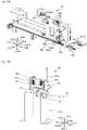
Figs. 5 and12 ,drum set unit 70 is provided with fixedunit 71 including fixedbase 71a fixed so as to be erected onupper plate 32, and movingunit 81 includingslide base 81a slidable in the X-axis direction and the Y-axis direction byslide unit 34 disposed onupper plate 32. As illustrated inFig. 13 , fixedunit 71 is provided with Y-axis slider 72, motor 73 (refer toFig. 6 ),pulley 74, Z-axis slider 75,motor 76,pulley 77,chuck 78, and chuckcylinder 78a. Y-axis slider 72 moves a front surface (right surface inFig. 13 ) of fixedbase 71a along the Y-axis direction (front-rear direction) by transmitting the driving force of motor 73 disposed on a rear surface (left surface inFig. 13 ) of fixedbase 71a viapulley 74. Z-axis slider 75 is provided on Y-axis slider 72, and moves in the Z-axis direction (up-down direction) along the front surface of Y-axis slider 72 by transmitting the driving force ofmotor 76 viapulley 77.Chuck 78 is provided on Z-axis slider 75, and holds splicingtape 116 of collectingdrum 115 by the operation ofchuck cylinder 78a. - As illustrated in
Figs. 12 and14 , movingunit 81 is provided withrotary transfer disc 82,motor 83,drum chuck 84,chuck cylinder 84a (refer toFig. 6 ),guide pin 85,pin cylinder 85a (refer toFig. 6 ),tape chuck 86,chuck cylinder 86a,motor 87, andpulley 88.Rotary transfer disc 82 is a disc-shaped member includingsupport shaft 82a to which drummain body 115a of collectingdrum 115 is attached to be installed and removed, and can rotate drummain body 115a by being rotated by the driving ofmotor 83. In addition,rotary transfer disc 82 is formed with multiplelong holes 82b (for example, three) extending in the radial direction at equal intervals in the circumferential direction.Drum chuck 84 is provided with multiple (three) chuck claws that move inlong hole 82b by the operation ofchuck cylinder 84a, and each chuck claw is opened and closed by the operation ofchuck cylinder 84a to grasp or release collectingdrum 115. Multiple guide pins 85 are provided so as to be erected from the left surface of movingunit 81 to fixedunit 71 side. Multiple guide pins 85 are provided at least at positions corresponding to each of guide pins 113 so that a path similar to the guide path for guidingcover tape 134 to collectingdrum 115 can be formed infeeder 100. Therefore, by movingchuck 78 holding a distal end ofsplicing tape 116 along the path formed byguide pin 85 by Y-axis slider 72 and Z-axis slider 75,drum set unit 70 can guideguide pin 85 so that splicingtape 116 crawls onguide pin 85 to form a path similar to the guide path infeeder 100. In addition, a part ofguide pin 85 is moved by the driving ofpin cylinder 85a, so that splicingtape 116 can be held by guide pins 85.Tape chuck 86 can hold the distal end ofsplicing tape 116 forming the guide path by the operation ofchuck cylinder 86a, and the distal end position of heldsplicing tape 116 can be adjusted by transmitting the driving force ofmotor 87 viapulley 88 and moving in the Y-axis direction. - As illustrated in
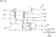
Figs. 15 and16 ,tape cutting unit 90 is provided withbase 90a, cuttingbase 91,tape feeding section 92,first tape cutter 95,second tape cutter 96,third tape cutter 97, andslider 98.Tape feeding section 92 is provided withsprocket 93 having a protrusion formed on an outer periphery for engaging with an engagement hole oftape 130, andmotor 94 for drivingsprocket 93. In a state wheretape 130 fed fromreel 120 ofreel transfer unit 60 with respect to the right end of cuttingbase 91 is engaged withsprocket 93,tape feeding section 92 rotatessprocket 93 by the forward rotation ofmotor 94 to feedtape 130 toward the cutting position. -
First tape cutter 95 has a scissor-shaped cutting blade disposed in a direction orthogonal to the feeding direction oftape 130, and is operated by the driving ofcutter cylinder 95a to cuttape 130. Insecond tape cutter 96, a cutting blade is disposed obliquely with respect to the feeding direction oftape 130, and the right side of the distal end oftape 130 is cut in a tapered manner by the driving ofcutter cylinder 96a. Inthird tape cutter 97, a cutting blade is disposed obliquely with respect to the feeding direction oftape 130, and the left side of the distal end oftape 130 is cut in a tapered manner by the driving ofcutter cylinder 97a.Third tape cutter 97 is provided onslider 98 that slides in the X-axis direction (left-right direction) above cuttingbase 91, and is movable in the left-right direction. Therefore, by adjusting the position ofthird tape cutter 97 in accordance with the width oftape 130,tape cutting unit 90 can cut in a tapered manner the left side of the distal end oftape 130 fed out with reference to the right end of cuttingbase 91. By cutting the distal end of tape 130 (cover tape 134) in a tapered manner, it is possible to prevent the distal end from being caught when insertingtape 130 intoloop 118, so thattape 130 can be smoothly inserted (refer toFig. 7 ). -
Control device 39 is provided withCPU 39a,ROM 39b,RAM 39c, and the like. Status information and the like are inputted from each unit of reel installation andremoval device 30, and status information onreel transfer robot 24 andloader 29, instruction for installation and removal ofreel 120, and the like are inputted frommanagement device 2 to controldevice 39.Control device 39 outputs a control signal to each unit of reel installation andremoval device 30 based on the information and the instruction for installation and removal to install and removereel 120 to and fromfeeder 100 set in feeder setunit 40. In addition to these configurations, reel installation andremoval device 30 may be provided with a camera capable of capturing an image of label 122 ofreel 120 attached tofeeder 100. In addition, whenreel 120 is detached fromfeeder 100 set in feeder setunit 40, a temporary fastening portion forfastening tape 130 with a temporary fastening tape may be provided, or a peeling portion for peeling the temporary fastening tape whenreel 120 is attached may be provided. - The following is a description of the operation of reel installation and
removal device 30 configured in this manner.Fig. 17 is a flowchart illustrating an example of a reel detachment process. The process is executed bycontrol device 39 in a case wherefeeder 100 as a detachment target fromreel 120 is set in feeder setunit 40. First,control device 39 causes cover opening andclosing unit 50 so as to open reel cover 106 (S100). As described above, since cover opening andclosing unit 50 holds reel cover 106 inopening 32a, reel cover 106 in the opened state can be prevented from interfering with the movement or operation of other units. Next,control device 39 controls slideunit 33 so thatreel transfer unit 60 moves to feeder set unit 40 (S105).Reel transfer unit 60 is in a state where push-turning disc 67 is attached to supportpin 61. Subsequently,control device 39 causesfeeder 100 and reeltransfer unit 60 set in feeder setunit 40 so as to reserve a predetermined length to rewind tape 130 (S110). In S110,control device 39 causes tape feeding section 102 offeeder 100 so as to rotate in the reverse direction, and controlsreel transfer unit 60 so as to push and turnreel 120 in the reverse rotation direction by push-turning disc 67. When S110 is ended,control device 39 causesreel transfer unit 60 so as to detach push-turning disc 67 fromsupport pin 61. - Here, in
first type feeder 100 using collectingdrum 115, since a distal end ofcover tape 134 is spliced tosplicing tape 116 whenreel 120 is attached (refer toFig. 8 ) next time, the length of tape 130 (cover tape 134) that needs to be reserved whenreel 120 is detached may be shortened. On the other hand, insecond type feeder 100 or the like using a take-up gear, it is necessary to reserve a length necessary forcover tape 134 to reach the take-up gear whenreel 120 is attached next time. In the present embodiment, in S110, a predetermined length is reserved according to the type requiring the longest length (here, second type) so thatreel 120 can handle any type offeeder 100 to be attached next time. - When
tape 130 is rewound,control device 39 causesreel transfer unit 60 so as to cuttape 130 to detachreel 120 from feeder 100 (S115).Reel transfer unit 60 cuts tape 130 by causingcutter 66 to enterfeeder 100. Next,control device 39 controls slideunit 33 so thatreel transfer unit 60 moves to reel set base 35 (S120), and causesreel transfer unit 60 so as to setdetached reel 120 on reel set base 35 (S125). When there are remaining components ontape 130, reel 120 set on reel setbase 35 is transferred tocradle 22a ofautomatic reel storage 22 byreel transfer robot 24. In addition,reel 120 having no remaining components is transferred to usedreel storage location 25 byreel transfer robot 24, or is discharged from a discharge port (not illustrated) formed inupper plate 32. - Subsequently,
control device 39 determines whetherfeeder 100 is the first type using collecting drum 115 (S130). When it is determined that the type is the first type,control device 39 controls slideunit 34 so that movingunit 81 of drum setunit 70 moves to feeder set unit 40 (S135). Next,control device 39 causes drumchuck 84 of movingunit 81 so as to detach collectingdrum 115 from feeder 100 (S140).Control device 39 controls slideunit 34 so that movingunit 81 moves to a standby position in front of fixedunit 71 or the like (S145). When it is determined in S130 that the type is not the first type,control device 39 skips S135 to S145. Collectingdrum 115 detached in S140 is assumed to be collected in a dust box or the like from a discharge port (not illustrated) formed inupper plate 32 until movingunit 81 moves to the standby position. The operator may detachcover tape 134 from collectingdrum 115 collected in the dust box, discardcover tape 134, and set collectingdrum 115 at a predetermined location where movingunit 81 of drum setunit 70 can receive collectingdrum 115. -
Control device 39 determines whetherreel 120 is attached tofeeder 100 set in feeder set unit 40 (S150). When it is determined thatreel 120 is not to be attached,control device 39 causes cover opening andclosing unit 50 so as to close reel cover 106 (S155), and ends the reel detachment process. On the other hand, when it is determined thatreel 120 is attached,control device 39 skips S155, and ends the reel detachment process while maintaining reel cover 106 open. - Next, an attachment process of the reel will be described.
Fig. 18 is a flowchart illustrating an example of the reel attachment process. The process is executed bycontrol device 39 in a case wherefeeder 100 as an attachment target to reel 120 is set in feeder setunit 40, for example, in a case where the reel detachment process inFig. 17 ends with reel cover 106 open, or the like. First,control device 39 controls slideunit 33 so thatreel transfer unit 60 moves to reel set base 35 (S200).Reel transfer unit 60 is in a state where push-turning disc 67 is detached fromsupport pin 61. Next,control device 39 causesreel transfer unit 60 to receivereel 120 set on reel set base 35 (S205). Subsequently,control device 39 controls slideunit 33 so thatreel transfer unit 60 moves to tape cutting unit 90 (S210).Reel transfer unit 60 andtape cutting unit 90 are controlled so that a necessary amount oftape 130 is fed fromreel 120 to cut the distal end oftape 130 into a necessary shape (S215). Whenfeeder 100 as an attachment target is the first type using collectingdrum 115,control device 39 causestape cutting unit 90 so as to cut in a tapered manner the distal end oftape 130 in order to be easily inserted intoloop 118 as described above. In addition, when such tapered cutting is not necessary,control device 39 causestape cutting unit 90 so as to cut only in a direction orthogonal to the longitudinal direction oftape 130, for example. The distal ends of alltapes 130 may be cut in a tapered manner. Whentape 130 is cut bytape cutting unit 90,control device 39 causesreel transfer unit 60 so as to rewindtape 130 and hold the distal end oftape 130 bychuck 64. - Subsequently,
control device 39 controls slideunit 33 so thatreel transfer unit 60 moves to feeder set unit 40 (S220). In a case where reel cover 106 offeeder 100 set in feeder setunit 40 is in the closed state,control device 39 causes cover opening andclosing unit 50 so as to open reel cover 106 before S220. Next,control device 39 causesreel transfer unit 60 andslide unit 33 so as to attachreel 120 tofeeder 100 set in feeder setunit 40, and move to a predetermined standby position (S225). -
Control device 39 determines whetherfeeder 100 is the required first type of collecting drum 115 (S230). When it is determined that the tape is the first type,control device 39 causes drum setunit 70 so as to causesplicing tape 116 to crawl along the path formed byguide pins 85, to holdsplicing tape 116 byguide pins 85, and to grasp and hold the distal end ofsplicing tape 116 by tape chuck 86 (S235). Next,control device 39 controls slideunit 34 so that movingunit 81 moves to feeder set unit 40 (S240). Subsequently,control device 39 causes drum setunit 70 so as to attach collectingdrum 115 andsplicing tape 116 tofeeder 100 of feeder set unit 40 (S245).Control device 39 attachessplicing tape 116 crawled along the path formed byguide pin 85 so as to pass splicingtape 116 to each guide pin 113 offeeder 100 in that state, and then causesdrum set unit 70 so as to release the holding ofsplicing tape 116 by guide pins 85. As a result,splicing tape 116 can be attached along the guide path offeeder 100. In addition, when it is determined in step S230 that collectingdrum 115 is not a necessary type,control device 39 skips S235 to S245.Control device 39 may execute S235 to S245 before S200 to S215, or may execute S235 to S245 in parallel with S200 to S215. -
Control device 39 causes feeder setunit 40 so as to perform a distal end process of tape 130 (S250). For example, whenfeeder 100 is the first type,control device 39 causes feeder setunit 40 so as to drawcover tape 134 and splicecover tape 134 tosplicing tape 116. In addition, whenfeeder 100 is the second type,control device 39 causes feeder setunit 40 so as to drawcover tape 134 and feed to the guide path. Whenreel 120 is attached in this manner,control device 39 causes cover opening andclosing unit 50 so as to close reel cover 106 (S255), and ends the reel attachment process. In a case where reel installation andremoval device 30 is provided with a camera capable of capturing an image of label 122 ofreel 120,control device 39 may cause the camera to capture an image of label 122 before closing reel cover 106, and may perform image processing on the captured image to recognize the information on label 122. Based on the recognized information,control device 39 may confirm whethercorrect reel 120 is attached, register the attachment in association withfeeder 100, or transmit the recognized information tomanagement device 2 together with the notification that the attachment ofreel 120 is completed. - Here, correspondences between the constituent elements of the present embodiment and constituent elements of the present disclosure will be clarified. Reel installation and
removal device 30 of the present embodiment corresponds to the reel installation and removal device of the present disclosure, feeder setunit 40 corresponds to a feeder set unit,reel transfer unit 60 corresponds to a reel transfer unit, chuck 64 corresponds to a holding section,cutter 66 corresponds to a cutting section, andcontrol device 39 corresponds to a control device. Collectingdrum 115 corresponds to a drum-shaped collecting section.Guide pin 85 corresponds to a path forming section,chuck 78, Y-axis slider 72, and Z-axis slider 75 correspond to a guide section,drum set unit 70 corresponds to a collecting section set unit, andtape splicing section 46 corresponds to a splicing section. Reel cover 106 corresponds to an opening and closing cover, and cover opening andclosing unit 50 corresponds to a cover opening and closing unit. In addition,preparation line 20 corresponds to a feeder preparation system,feeder storage 26 corresponds to a feeder storage section,loader 29 corresponds to a feeder preparation device, reel setbase 35 corresponds to a reel set base, and reeltransfer robot 24 corresponds to a reel preparation device. - In reel installation and
removal device 30 described above, sincefeeder 100 is set on feeder setunit 40 so that tape feeding section 102 (feeding section) can be driven,tape 130 can be quickly rewound whenreel 120 is detached. In addition,reel transfer unit 60 rotates push-turning disc 67, so thattape 130 can be appropriately rewound onreel 120. In addition,tape 130 is rewound to a portion to which the component has been supplied and cut, so that it is possible to prevent the component from falling off by the distal end process oftape 130 whenreel 120 is attached next time. As a result, reel 120 can be more appropriately detached. - In addition, since tape 130 (cover tape 134) is rewound so as to reserve a predetermined length, it is possible to suppress the time required for the process to collect
cover tape 134 whenreel 120 is attached next time. In addition, since splicingtape 116 is attached tofeeder 100 after being along disposed the guide path ofcover tape 134,drum set unit 70 can efficiently attach collectingdrum 115. In addition, since the detachment and attachment ofreel 120 are performed by a common device, reel installation andremoval device 30 can be configured to be more compact than those performed by separate devices. In addition, since reel cover 106 in the opened state is held at a position that does not interfere with the movement of other units, cover opening andclosing unit 50 can further efficiently detach and attach the reel. - It is needless to say that the present disclosure is not limited to the embodiments described above, and various forms can be implemented within the technical scope of the present disclosure.
- For example, in the above embodiment,
tape 130 is rewound by reserving a predetermined length whenreel 120 is detached; however, the configuration is not limited to this, and, for example, an extension tape having a necessary length may be added to the distal end oftape 130 whenreel 120 is attached next time. - In the above embodiment, both
chuck 64 andcutter 66 are provided inreel transfer unit 60; however, the configuration is not limited to this, either or both may be provided in a place other thanreel transfer unit 60, and, for example, may be provided in feeder setunit 40. - In the above embodiment,
first type feeder 100 to be collected by collectingdrum 115 is exemplified, and drum setunit 70 that installs and removes collectingdrum 115 and forms the path ofsplicing tape 116 is provided; however, the configuration is not limited to this. For example,reel transfer unit 60 may detach collectingdrum 115 together withreel 120 instead of drum setunit 70. In addition, the path formation ofsplicing tape 116 may be performed by feeder setunit 40 orreel transfer unit 60 after collectingdrum 115 is attached tofeeder 100. In such a case or in a case wherefirst type feeder 100 is not handled,drum set unit 70 need not be provided. - In the above embodiment, an example in which reel cover 106 is attached to the lower edge of
feeder 100 in an openable and closable manner is exemplified; however, the configuration is not limited to this, reel cover 106 may be attached tofeeder 100 in an openable and closable manner, and the opening and closing direction may be the left-right direction. - In the above embodiment,
feeder 100 is set such that feeder setunit 40 can drive tape feeding section 102; however, the configuration is not limited to this, andfeeder 100 may be set such that tape feeding section 102 cannot be driven. In addition, althoughreel transfer unit 60 is configured to push and turnreel 120 by using push-turning disc 67,reel 120 may be rotated by a method other than push-turning. Alternatively,reel transfer unit 60 may not rotate reel 120 (may not include a rotation section). In addition,control device 39 may be driven at least chuck 64 (holding section) and cutter 66 (cutting section) so as to hold and cuttape 130 at the portion to which the component has been supplied, in a state wherefeeder 100 to whichreel 120 is attached is set in feeder setunit 40. - In the above embodiment, in addition to reel installation and
removal device 30, preparation line 20 (preparation system) includingloader 29 for settingfeeder 100 in feeder setunit 40,reel transfer robot 24 for settingreel 120 in reel setbase 35, and the like is exemplified; however, the configuration is not limited to this. Reel installation andremoval device 30 is individually disposed, and the set offeeder 100 and the set ofreel 120 may be performed by another device such as AGV, or may be performed by an operator. In addition, the disposition of each unit of reel installation andremoval device 30 and the function of each unit are examples, and reel installation andremoval device 30 as a whole may be configured to automatically install and removereel 120 with respect tofeeder 100. - Here, the reel installation and removal device of the present disclosure may be configured as follows. In the reel installation and removal device of the present disclosure, the tape may include a bottom tape accommodating the component and a cover tape covering the component, and may be capable of supplying the component by peeling off the cover tape, as the feeder, multiple types of feeders including a type having a drum-shaped collecting section collecting the cover tape while winding the cover tape together with a splicing tape to which a distal end is spliced to the cover tape and a type in which the cover tape is pulled and collected to the collecting section different from the drum shape may be provided, and the control device may drive the driving section and the rotation section to rewind the cover tape by reserving a length adaptable for any type when the reel is attached to the feeder next time in the detachment control. Accordingly, it is possible to appropriately detach the reel in consideration of the case where the reel is attached next time. Therefore, it is possible to efficiently perform the automatic attachment of the reel while suppressing the time required for the process to collect the cover tape when the reel is attached next time.
- In the reel installation and removal device according to the present disclosure, the feeder may be provided with a guide path guiding the cover tape to the collecting section, the device further may include a collecting section set unit configured to be moved relative to the feeder set unit, having a path forming section forming a path along the guide path and a guide section guiding the splicing tape to crawl on the path forming section, and configured to transfer the drum-shaped collecting section, the feeder set unit may include a splicing section configured to splice a distal end of the splicing tape and a distal end of the peeled cover tape, and the control device may cause the collecting section set unit so as to attach the splicing tape and the collecting section to the feeder set in the feeder set unit, and may control the feeder set unit so that the splicing section splices the distal end of the splicing tape and the distal end of the cover tape, after the splicing tape is crawled on the path forming section in advance in the collecting section set unit. Accordingly, in a feeder of a type using the drum-shaped collecting section, it is possible to efficiently attach the reel and the collecting section.
- In the reel installation and removal device of the present disclosure, the control device may execute an attachment control of attaching the reel to the feeder in a state where the feeder from which the reel is detached is set in the feeder set unit, driving the holding section and the rotation section so that a distal end of the tape is fed from the reel to the feeding section, and controlling the feeder set unit and the reel transfer unit so that the feeding section is driven until the distal end of the tape reaches a predetermined position. Accordingly, since the detachment and the attachment of the reels can be performed by a common installation and removal device, the installation and removal device can be configured to be compact.
- In the reel installation and removal device of the present disclosure, the feeder may include an opening and closing cover that exposes the reel in an opened state to be installed and removed, the device further includes a cover opening and closing unit configured to open and close the opening and closing cover of the feeder set in the feeder set unit, and to hold the opening and closing cover in the opened state at a position not interfering with a relative movement of other units to the feeder set unit. Accordingly, the installation and removal of the reel can be further efficiently performed.
- It is a gist that another reel installation and removal device of the present disclosure is a reel installation and removal device that installs and removes a reel on which a tape accommodating a component is wound to and from a feeder which feeds the tape by driving of a feeding section and supplies the component, the device including a feeder set unit on which the feeder is set, a holding section configured to hold the tape of the reel mounted on the feeder, a cutting section configured to cut the tape, and a control device configured to drive the holding section and the cutting section so that the tape is held and cut at a portion to which the component has been supplied, in a state where the feeder to which the reel is attached is set in the feeder set unit. Even in this manner, since it is possible to prevent the component from being affected by the distal end process of the tape when the reel is attached next time by cutting the tape at the portion to which the component has been supplied, it is possible to more appropriately detach the reel in a case where the installation and removal of the reel is automatically performed.
- It is a gist that a feeder preparation system of the present disclosure includes any of the reel installation and removal devices described above, a feeder preparation device configured to transfer the feeder between a feeder storage section storing multiple feeders and the feeder set unit, and to prepare the feeder as an installation and removal target of the reel, a reel set base on which the reel is set so that the reel transfer unit is transferred, and a reel preparation device configured to transfer the reel between a reel storage section storing multiple reels and the reel set base, and to prepare the reel as an installation and removal target to the feeder.
- In the feeder preparation system of the present disclosure, since the reel is automatically installed and removed to and from the feeder by any of the reel installation and removal devices described above, it is possible to more appropriately detach the reel. In addition, since the preparation of the feeder and the preparation of the reel can also be automatically performed, the automatic installation and removal of the reel can be further efficiently performed.
- The present disclosure can be used in the manufacturing industry of component mounting systems and the like.
- 1 component mounting system, 2 management device, 4 AGV, 10 mounting line, 12 printing device, 14 printing inspection device, 16 mounting device, 18 feeder storage location, 19 loader, 20 preparation line, 22 automatic reel storage, 22a cradle, 24 reel transfer robot, 25 reel storage location, 26 feeder storage, 28 feeder storage location, 29 loader, 30 reel installation and removal device, 31 base plate, 32 upper plate, 32a opening, 33, 34 slide unit, 35 reel set base, 36 base, 37 support pin, 39 control device, 39a CPU, 39b ROM, 39c RAM, 40 feeder set unit, 40a base, 42 guide opening and closing section, 44 tape drawing section, 46 tape splicing section, 47 fixed clamp section, 47a, 47b, 48a, 48b clamp member, 47c, 48c clamp cylinder, 48 moving clamp section, 49 slide section, 49a slide block, 49b slide cylinder, 50 cover opening and closing unit, 50a base, 52 support column, 53 pivot plate, 54 pickup platen, 55 motor, 56 pulley, 60 reel transfer unit, 60a slide base, 61 support pin, 61a expanding cylinder, 62 motor, 63 push-in plate, 63a push-in cylinder, 64 chuck, 64a chuck cylinder, 65 guide pin, 66 cutter, 66a cutter cylinder, 67 push-turning disc, 68 buffer member, 70 drum set unit, 71 fixed unit, 71a fixed base, 72 Y-axis slider, 73 motor, 74 pulley, 75 Z-axis slider, 76 motor, 77 pulley, 78 chuck, 78a chuck cylinder, 81 moving unit, 81a slide base, 82 rotary transfer disc, 82a support shaft, 82b long hole, 83 motor, 84 drum chuck, 84a chuck cylinder, 85 guide pin, 85a pin cylinder, 86 tape chuck, 86a chuck cylinder, 87 motor, 88 pulley, 90 tape cutting unit, 90a base, 91 cutting base, 92 tape feeding section, 93 sprocket, 94 motor, 95 first tape cutter, 95a, 96a, 97a cutter cylinder, 96 second tape cutter, 97 third tape cutter, 98 slider, 100 feeder, 101 main body, 102 tape feeding section, 103 motor, 104 tape guide, 106 reel cover, 108 connector, 109 positioning pin, 110 tape collecting section, 111 drum shaft, 113 guide pin, 115 collecting drum, 115a drum main body, 116 splicing tape, 117 fixing piece, 118 loop, 119 slide piece, 120 reel, 122 label, 130 tape, 132 bottom tape, 134 cover tape
Claims (7)
- A reel installation and removal device that installs and removes a reel on which a tape accommodating a component is wound to and from a feeder which feeds the tape by driving of a feeding section and supplies the component, the device comprising:a feeder set unit on which the feeder is set so that the feeding section is driven;a reel transfer unit including a rotation section rotating the reel around a shaft, and configured to move relative to the feeder set unit to transfer the reel;a holding section configured to hold the tape of the reel mounted on the feeder;a cutting section configured to cut the tape; anda control device configured to execute a detachment control of driving the holding section and the cutting section so that the tape is held and cut in a portion to which the component has been supplied after driving the feeding section and the rotation section so that the tape is rewound and to be wound around the reel, and controlling the feeder set unit and the reel transfer unit so as to detach the reel from the feeder, in a state where the feeder to which the reel is attached is set in the feeder set unit.
- The reel installation and removal device according to claim 1, whereinthe tape includes a bottom tape accommodating the component and a cover tape covering the component, and is capable of supplying the component by peeling off the cover tape,as the feeder, multiple types of feeders including a type having a drum-shaped collecting section collecting the cover tape while winding the cover tape together with a splicing tape to which a distal end is spliced to the cover tape and a type in which the cover tape is pulled and collected to the collecting section different from the drum shape are provided, andthe control device drives the driving section and the rotation section to rewind the cover tape by reserving a length adaptable for any type when the reel is attached to the feeder next time in the detachment control.
- The reel installation and removal device according to claim 2, whereinthe feeder is provided with a guide path guiding the cover tape to the collecting section,the device further comprises a collecting section set unit configured to be moved relative to the feeder set unit, including a path forming section forming a path along the guide path and a guide section guiding the splicing tape to crawl on the path forming section, and configured to transfer the drum-shaped collecting section,the feeder set unit includes a splicing section configured to splice a distal end of the splicing tape and a distal end of the peeled cover tape, andthe control device causes the collecting section set unit so as to attach the splicing tape and the collecting section to the feeder set in the feeder set unit, and controls the feeder set unit so that the splicing section splices the distal end of the splicing tape and the distal end of the cover tape, after the splicing tape is crawled on the path forming section in advance in the collecting section set unit.
- The reel installation and removal device according to any one of claims 1 to 3, wherein
the control device executes an attachment control of attaching the reel to the feeder in a state where the feeder from which the reel is detached is set in the feeder set unit, driving the holding section and the rotation section so that a distal end of the tape is fed from the reel to the feeding section, and controlling the feeder set unit and the reel transfer unit so that the feeding section is driven until the distal end of the tape reaches a predetermined position. - The reel installation and removal device according to any one of claims 1 to 4, whereinthe feeder includes an opening and closing cover that exposes the reel in an opened state to be installed and removed,the device further comprises a cover opening and closing unit configured to open and close the opening and closing cover of the feeder set in the feeder set unit, and to hold the opening and closing cover in the opened state at a position not interfering with a relative movement of other units to the feeder set unit.
- A reel installation and removal device that installs and removes a reel on which a tape accommodating a component is wound to and from a feeder which feeds the tape by driving of a feeding section and supplies the component, the device comprising:a feeder set unit on which the feeder is set;a holding section configured to hold the tape of the reel mounted on the feeder;a cutting section configured to cut the tape; anda control device configured to drive the holding section and the cutting section so that the tape is held and cut at a portion to which the component has been supplied, in a state where the feeder to which the reel is attached is set in the feeder set unit.
- A feeder preparation system comprising:the reel installation and removal device according to any one of claims 1 to 6;a feeder preparation device configured to transfer the feeder between a feeder storage section storing multiple feeders and the feeder set unit, and to prepare the feeder as an installation and removal target of the reel;a reel set base on which the reel is set so that the reel transfer unit is transferred; anda reel preparation device configured to transfer the reel between a reel storage section storing multiple reels and the reel set base, and to prepare the reel as an installation and removal target to the feeder.
Applications Claiming Priority (1)
| Application Number | Priority Date | Filing Date | Title |
|---|---|---|---|
| PCT/JP2020/012069 WO2021186632A1 (en) | 2020-03-18 | 2020-03-18 | Reel installation and removal device and feeder preparation system |
Publications (3)
| Publication Number | Publication Date |
|---|---|
| EP4124199A1 true EP4124199A1 (en) | 2023-01-25 |
| EP4124199A4 EP4124199A4 (en) | 2023-04-26 |
| EP4124199B1 EP4124199B1 (en) | 2024-10-02 |
Family
ID=77771758
Family Applications (1)
| Application Number | Title | Priority Date | Filing Date |
|---|---|---|---|
| EP20925391.3A Active EP4124199B1 (en) | 2020-03-18 | 2020-03-18 | Reel installation and removal device and feeder preparation system |
Country Status (5)
| Country | Link |
|---|---|
| US (1) | US12520467B2 (en) |
| EP (1) | EP4124199B1 (en) |
| JP (3) | JP7356574B2 (en) |
| CN (1) | CN115004879B (en) |
| WO (1) | WO2021186632A1 (en) |
Families Citing this family (13)
| Publication number | Priority date | Publication date | Assignee | Title |
|---|---|---|---|---|
| WO2021186632A1 (en) * | 2020-03-18 | 2021-09-23 | 株式会社Fuji | Reel installation and removal device and feeder preparation system |
| DE112021001834T5 (en) * | 2020-03-25 | 2023-01-12 | Panasonic Intellectual Property Management Co., Ltd. | Carrier tape processing device and carrier tape processing method |
| WO2023145058A1 (en) * | 2022-01-31 | 2023-08-03 | 株式会社Fuji | Feeder, component mounting apparatus, and component mounting method |
| JP7825364B2 (en) * | 2022-02-10 | 2026-03-06 | 株式会社Fuji | Reel Loader |
| JPWO2023188381A1 (en) * | 2022-03-31 | 2023-10-05 | ||
| WO2024013859A1 (en) * | 2022-07-12 | 2024-01-18 | ヤマハ発動機株式会社 | Component mounting system |
| DE112022007601T5 (en) * | 2022-07-28 | 2025-05-15 | Fuji Corporation | Coil working device |
| WO2024079781A1 (en) * | 2022-10-11 | 2024-04-18 | 株式会社Fuji | Kitting device |
| CN121488599A (en) * | 2023-08-30 | 2026-02-06 | 株式会社富士 | feeder |
| WO2025134266A1 (en) * | 2023-12-20 | 2025-06-26 | 株式会社Fuji | Tape feeder, feeder processing device, and feeder processing method |
| WO2025141742A1 (en) * | 2023-12-27 | 2025-07-03 | 株式会社Fuji | Tape automatic kitting device |
| WO2025234038A1 (en) * | 2024-05-08 | 2025-11-13 | 株式会社Fuji | Tape removal system |
| WO2026062785A1 (en) * | 2024-09-18 | 2026-03-26 | 株式会社Fuji | Feeder storage system |
Family Cites Families (22)
| Publication number | Priority date | Publication date | Assignee | Title |
|---|---|---|---|---|
| JPH05175686A (en) * | 1991-07-23 | 1993-07-13 | Matsushita Electric Works Ltd | Tape reel and tape-component feed apparatus |
| JP3653337B2 (en) | 1996-05-20 | 2005-05-25 | 信越ポリマー株式会社 | Tape take-up device |
| JPH1187991A (en) * | 1997-09-10 | 1999-03-30 | Toshiba Fa Syst Eng Kk | Automatic setup device for chip type taping |
| JP3637790B2 (en) * | 1998-10-07 | 2005-04-13 | 松下電器産業株式会社 | Tape feeder |
| US6433953B1 (en) * | 1998-12-11 | 2002-08-13 | Sony Corporation | Recording/reproducing apparatus |
| JP2001284885A (en) * | 2000-03-31 | 2001-10-12 | Sanyo Electric Co Ltd | Cover tape take up mechanism of electronic component feeder |
| US7220095B2 (en) * | 2001-05-24 | 2007-05-22 | Lyndaker David W | Self-threading component tape feeder |
| JP3820927B2 (en) * | 2001-07-06 | 2006-09-13 | 松下電器産業株式会社 | Tape feeder |
| JP2003051696A (en) * | 2001-08-03 | 2003-02-21 | Tokai Rika Co Ltd | Method for changing reel in tape feeder and the tape feeder |
| JP2006303059A (en) * | 2005-04-19 | 2006-11-02 | Matsushita Electric Ind Co Ltd | Parts feeder and electronic component mounting method |
| JP2013235900A (en) * | 2012-05-07 | 2013-11-21 | Juki Corp | Reel holder and electronic component feeding device |
| JP6212272B2 (en) * | 2013-03-29 | 2017-10-11 | 富士機械製造株式会社 | Electronic component management system |
| JP6167300B2 (en) * | 2013-09-26 | 2017-07-26 | パナソニックIpマネジメント株式会社 | Component mounting apparatus and component mounting method |
| WO2015121976A1 (en) * | 2014-02-14 | 2015-08-20 | 富士機械製造株式会社 | Feeder exchange device |
| JP6427003B2 (en) * | 2014-12-25 | 2018-11-21 | ヤマハ発動機株式会社 | Electronic component supply apparatus, reel device, and component storage tape replenishment method |
| US10660249B2 (en) * | 2015-09-09 | 2020-05-19 | Fuji Corporation | Separate installation-type reel holding device |
| JP6921548B2 (en) * | 2017-02-22 | 2021-08-18 | 株式会社Fuji | Reel holder |
| CN111587614B (en) * | 2018-01-19 | 2021-09-10 | 株式会社富士 | Storage device and storage method with reel |
| JP7108809B2 (en) * | 2018-05-23 | 2022-07-29 | パナソニックIpマネジメント株式会社 | Component tape mounting device and component tape mounting method |
| CN112205094B (en) * | 2018-05-31 | 2021-11-23 | 株式会社富士 | Feeder and component mounting machine |
| JP6839749B2 (en) * | 2019-11-19 | 2021-03-10 | 株式会社Fuji | Tape feeder |
| WO2021186632A1 (en) * | 2020-03-18 | 2021-09-23 | 株式会社Fuji | Reel installation and removal device and feeder preparation system |
-
2020
- 2020-03-18 WO PCT/JP2020/012069 patent/WO2021186632A1/en not_active Ceased
- 2020-03-18 JP JP2022508717A patent/JP7356574B2/en active Active
- 2020-03-18 US US17/906,311 patent/US12520467B2/en active Active
- 2020-03-18 EP EP20925391.3A patent/EP4124199B1/en active Active
- 2020-03-18 CN CN202080094942.4A patent/CN115004879B/en active Active
-
2023
- 2023-09-22 JP JP2023156630A patent/JP7604587B2/en active Active
-
2024
- 2024-12-10 JP JP2024215190A patent/JP7848296B2/en active Active
Also Published As
| Publication number | Publication date |
|---|---|
| JP7604587B2 (en) | 2024-12-23 |
| JP2023164713A (en) | 2023-11-10 |
| JP7356574B2 (en) | 2023-10-04 |
| JP7848296B2 (en) | 2026-04-20 |
| EP4124199B1 (en) | 2024-10-02 |
| JPWO2021186632A1 (en) | 2021-09-23 |
| WO2021186632A1 (en) | 2021-09-23 |
| CN115004879A (en) | 2022-09-02 |
| EP4124199A4 (en) | 2023-04-26 |
| JP2025026634A (en) | 2025-02-21 |
| US20230089639A1 (en) | 2023-03-23 |
| US12520467B2 (en) | 2026-01-06 |
| CN115004879B (en) | 2023-11-28 |
Similar Documents
| Publication | Publication Date | Title |
|---|---|---|
| EP4124199B1 (en) | Reel installation and removal device and feeder preparation system | |
| US12479683B2 (en) | Reel attaching/detaching device and feeder preparation system | |
| CN107135642B (en) | Component supply device | |
| EP3806604B1 (en) | Unit exchanging device | |
| JP2006173537A (en) | Cover tape peeling method, component supply device, and surface mounter | |
| CN112205094A (en) | Feeder and component mounting machine | |
| JP2026074145A (en) | Setup device | |
| US20240373610A1 (en) | Feeder setup device and feeder setup system | |
| JP7834833B2 (en) | Feeder setup device | |
| US20230371224A1 (en) | Management device, management method, and work device | |
| JP7825364B2 (en) | Reel Loader | |
| JP7611396B2 (en) | Component placement machine | |
| CN112123355B (en) | Robot hand and robot | |
| JP7761680B2 (en) | Reel Loader | |
| CN119213883A (en) | Method for automatically reloading a reel of SMD components on an SMD assembly machine | |
| WO2024079781A1 (en) | Kitting device | |
| JP2025002434A (en) | Component mounting system and component mounting method | |
| WO2024100749A1 (en) | Reel loading device | |
| WO2025004182A1 (en) | Fastening tape peeling device | |
| WO2023188381A1 (en) | Setup system and setup method | |
| CN122035557A (en) | Feeder |
Legal Events
| Date | Code | Title | Description |
|---|---|---|---|
| STAA | Information on the status of an ep patent application or granted ep patent |
Free format text: STATUS: THE INTERNATIONAL PUBLICATION HAS BEEN MADE |
|
| PUAI | Public reference made under article 153(3) epc to a published international application that has entered the european phase |
Free format text: ORIGINAL CODE: 0009012 |
|
| STAA | Information on the status of an ep patent application or granted ep patent |
Free format text: STATUS: REQUEST FOR EXAMINATION WAS MADE |
|
| 17P | Request for examination filed |
Effective date: 20220919 |
|
| AK | Designated contracting states |
Kind code of ref document: A1 Designated state(s): AL AT BE BG CH CY CZ DE DK EE ES FI FR GB GR HR HU IE IS IT LI LT LU LV MC MK MT NL NO PL PT RO RS SE SI SK SM TR |
|
| A4 | Supplementary search report drawn up and despatched |
Effective date: 20230328 |
|
| RIC1 | Information provided on ipc code assigned before grant |
Ipc: H05K 13/04 20060101ALI20230322BHEP Ipc: H05K 13/02 20060101AFI20230322BHEP |
|
| P01 | Opt-out of the competence of the unified patent court (upc) registered |
Effective date: 20230328 |
|
| DAV | Request for validation of the european patent (deleted) | ||
| DAX | Request for extension of the european patent (deleted) | ||
| GRAP | Despatch of communication of intention to grant a patent |
Free format text: ORIGINAL CODE: EPIDOSNIGR1 |
|
| STAA | Information on the status of an ep patent application or granted ep patent |
Free format text: STATUS: GRANT OF PATENT IS INTENDED |
|
| INTG | Intention to grant announced |
Effective date: 20240625 |
|
| GRAS | Grant fee paid |
Free format text: ORIGINAL CODE: EPIDOSNIGR3 |
|
| GRAA | (expected) grant |
Free format text: ORIGINAL CODE: 0009210 |
|
| STAA | Information on the status of an ep patent application or granted ep patent |
Free format text: STATUS: THE PATENT HAS BEEN GRANTED |
|
| AK | Designated contracting states |
Kind code of ref document: B1 Designated state(s): AL AT BE BG CH CY CZ DE DK EE ES FI FR GB GR HR HU IE IS IT LI LT LU LV MC MK MT NL NO PL PT RO RS SE SI SK SM TR |
|
| REG | Reference to a national code |
Ref country code: GB Ref legal event code: FG4D |
|
| REG | Reference to a national code |
Ref country code: CH Ref legal event code: EP |
|
| REG | Reference to a national code |
Ref country code: IE Ref legal event code: FG4D |
|
| REG | Reference to a national code |
Ref country code: DE Ref legal event code: R096 Ref document number: 602020038865 Country of ref document: DE |
|
| REG | Reference to a national code |
Ref country code: LT Ref legal event code: MG9D |
|
| REG | Reference to a national code |
Ref country code: NL Ref legal event code: MP Effective date: 20241002 |
|
| REG | Reference to a national code |
Ref country code: AT Ref legal event code: MK05 Ref document number: 1729458 Country of ref document: AT Kind code of ref document: T Effective date: 20241002 |
|
| PG25 | Lapsed in a contracting state [announced via postgrant information from national office to epo] |
Ref country code: NL Free format text: LAPSE BECAUSE OF FAILURE TO SUBMIT A TRANSLATION OF THE DESCRIPTION OR TO PAY THE FEE WITHIN THE PRESCRIBED TIME-LIMIT Effective date: 20241002 |
|
| PG25 | Lapsed in a contracting state [announced via postgrant information from national office to epo] |
Ref country code: NL Free format text: LAPSE BECAUSE OF FAILURE TO SUBMIT A TRANSLATION OF THE DESCRIPTION OR TO PAY THE FEE WITHIN THE PRESCRIBED TIME-LIMIT Effective date: 20241002 |
|
| PG25 | Lapsed in a contracting state [announced via postgrant information from national office to epo] |
Ref country code: HR Free format text: LAPSE BECAUSE OF FAILURE TO SUBMIT A TRANSLATION OF THE DESCRIPTION OR TO PAY THE FEE WITHIN THE PRESCRIBED TIME-LIMIT Effective date: 20241002 Ref country code: IS Free format text: LAPSE BECAUSE OF FAILURE TO SUBMIT A TRANSLATION OF THE DESCRIPTION OR TO PAY THE FEE WITHIN THE PRESCRIBED TIME-LIMIT Effective date: 20250202 Ref country code: PT Free format text: LAPSE BECAUSE OF FAILURE TO SUBMIT A TRANSLATION OF THE DESCRIPTION OR TO PAY THE FEE WITHIN THE PRESCRIBED TIME-LIMIT Effective date: 20250203 |
|
| PG25 | Lapsed in a contracting state [announced via postgrant information from national office to epo] |
Ref country code: FI Free format text: LAPSE BECAUSE OF FAILURE TO SUBMIT A TRANSLATION OF THE DESCRIPTION OR TO PAY THE FEE WITHIN THE PRESCRIBED TIME-LIMIT Effective date: 20241002 |
|
| PG25 | Lapsed in a contracting state [announced via postgrant information from national office to epo] |
Ref country code: BG Free format text: LAPSE BECAUSE OF FAILURE TO SUBMIT A TRANSLATION OF THE DESCRIPTION OR TO PAY THE FEE WITHIN THE PRESCRIBED TIME-LIMIT Effective date: 20241002 |
|
| PG25 | Lapsed in a contracting state [announced via postgrant information from national office to epo] |
Ref country code: ES Free format text: LAPSE BECAUSE OF FAILURE TO SUBMIT A TRANSLATION OF THE DESCRIPTION OR TO PAY THE FEE WITHIN THE PRESCRIBED TIME-LIMIT Effective date: 20241002 |
|
| PG25 | Lapsed in a contracting state [announced via postgrant information from national office to epo] |
Ref country code: NO Free format text: LAPSE BECAUSE OF FAILURE TO SUBMIT A TRANSLATION OF THE DESCRIPTION OR TO PAY THE FEE WITHIN THE PRESCRIBED TIME-LIMIT Effective date: 20250102 |
|
| PG25 | Lapsed in a contracting state [announced via postgrant information from national office to epo] |
Ref country code: AT Free format text: LAPSE BECAUSE OF FAILURE TO SUBMIT A TRANSLATION OF THE DESCRIPTION OR TO PAY THE FEE WITHIN THE PRESCRIBED TIME-LIMIT Effective date: 20241002 Ref country code: LV Free format text: LAPSE BECAUSE OF FAILURE TO SUBMIT A TRANSLATION OF THE DESCRIPTION OR TO PAY THE FEE WITHIN THE PRESCRIBED TIME-LIMIT Effective date: 20241002 Ref country code: GR Free format text: LAPSE BECAUSE OF FAILURE TO SUBMIT A TRANSLATION OF THE DESCRIPTION OR TO PAY THE FEE WITHIN THE PRESCRIBED TIME-LIMIT Effective date: 20250103 |
|
| PG25 | Lapsed in a contracting state [announced via postgrant information from national office to epo] |
Ref country code: CZ Free format text: LAPSE BECAUSE OF FAILURE TO SUBMIT A TRANSLATION OF THE DESCRIPTION OR TO PAY THE FEE WITHIN THE PRESCRIBED TIME-LIMIT Effective date: 20241002 Ref country code: PL Free format text: LAPSE BECAUSE OF FAILURE TO SUBMIT A TRANSLATION OF THE DESCRIPTION OR TO PAY THE FEE WITHIN THE PRESCRIBED TIME-LIMIT Effective date: 20241002 |
|
| PG25 | Lapsed in a contracting state [announced via postgrant information from national office to epo] |
Ref country code: RS Free format text: LAPSE BECAUSE OF FAILURE TO SUBMIT A TRANSLATION OF THE DESCRIPTION OR TO PAY THE FEE WITHIN THE PRESCRIBED TIME-LIMIT Effective date: 20250102 |
|
| PG25 | Lapsed in a contracting state [announced via postgrant information from national office to epo] |
Ref country code: SM Free format text: LAPSE BECAUSE OF FAILURE TO SUBMIT A TRANSLATION OF THE DESCRIPTION OR TO PAY THE FEE WITHIN THE PRESCRIBED TIME-LIMIT Effective date: 20241002 |
|
| REG | Reference to a national code |
Ref country code: DE Ref legal event code: R097 Ref document number: 602020038865 Country of ref document: DE |
|
| PG25 | Lapsed in a contracting state [announced via postgrant information from national office to epo] |
Ref country code: DK Free format text: LAPSE BECAUSE OF FAILURE TO SUBMIT A TRANSLATION OF THE DESCRIPTION OR TO PAY THE FEE WITHIN THE PRESCRIBED TIME-LIMIT Effective date: 20241002 |
|
| PG25 | Lapsed in a contracting state [announced via postgrant information from national office to epo] |
Ref country code: EE Free format text: LAPSE BECAUSE OF FAILURE TO SUBMIT A TRANSLATION OF THE DESCRIPTION OR TO PAY THE FEE WITHIN THE PRESCRIBED TIME-LIMIT Effective date: 20241002 |
|
| PG25 | Lapsed in a contracting state [announced via postgrant information from national office to epo] |
Ref country code: RO Free format text: LAPSE BECAUSE OF FAILURE TO SUBMIT A TRANSLATION OF THE DESCRIPTION OR TO PAY THE FEE WITHIN THE PRESCRIBED TIME-LIMIT Effective date: 20241002 |
|
| PG25 | Lapsed in a contracting state [announced via postgrant information from national office to epo] |
Ref country code: SK Free format text: LAPSE BECAUSE OF FAILURE TO SUBMIT A TRANSLATION OF THE DESCRIPTION OR TO PAY THE FEE WITHIN THE PRESCRIBED TIME-LIMIT Effective date: 20241002 |
|
| PG25 | Lapsed in a contracting state [announced via postgrant information from national office to epo] |
Ref country code: IT Free format text: LAPSE BECAUSE OF FAILURE TO SUBMIT A TRANSLATION OF THE DESCRIPTION OR TO PAY THE FEE WITHIN THE PRESCRIBED TIME-LIMIT Effective date: 20241002 |
|
| PLBE | No opposition filed within time limit |
Free format text: ORIGINAL CODE: 0009261 |
|
| STAA | Information on the status of an ep patent application or granted ep patent |
Free format text: STATUS: NO OPPOSITION FILED WITHIN TIME LIMIT |
|
| PG25 | Lapsed in a contracting state [announced via postgrant information from national office to epo] |
Ref country code: SE Free format text: LAPSE BECAUSE OF FAILURE TO SUBMIT A TRANSLATION OF THE DESCRIPTION OR TO PAY THE FEE WITHIN THE PRESCRIBED TIME-LIMIT Effective date: 20241002 |
|
| 26N | No opposition filed |
Effective date: 20250703 |
|
| PG25 | Lapsed in a contracting state [announced via postgrant information from national office to epo] |
Ref country code: MC Free format text: LAPSE BECAUSE OF FAILURE TO SUBMIT A TRANSLATION OF THE DESCRIPTION OR TO PAY THE FEE WITHIN THE PRESCRIBED TIME-LIMIT Effective date: 20241002 |
|
| REG | Reference to a national code |
Ref country code: CH Ref legal event code: H13 Free format text: ST27 STATUS EVENT CODE: U-0-0-H10-H13 (AS PROVIDED BY THE NATIONAL OFFICE) Effective date: 20251023 |
|
| PG25 | Lapsed in a contracting state [announced via postgrant information from national office to epo] |
Ref country code: LU Free format text: LAPSE BECAUSE OF NON-PAYMENT OF DUE FEES Effective date: 20250318 |
|
| GBPC | Gb: european patent ceased through non-payment of renewal fee |
Effective date: 20250318 |
|
| REG | Reference to a national code |
Ref country code: BE Ref legal event code: MM Effective date: 20250331 |
|
| PG25 | Lapsed in a contracting state [announced via postgrant information from national office to epo] |
Ref country code: GB Free format text: LAPSE BECAUSE OF NON-PAYMENT OF DUE FEES Effective date: 20250318 |
|
| PG25 | Lapsed in a contracting state [announced via postgrant information from national office to epo] |
Ref country code: FR Free format text: LAPSE BECAUSE OF NON-PAYMENT OF DUE FEES Effective date: 20250331 |
|
| PG25 | Lapsed in a contracting state [announced via postgrant information from national office to epo] |
Ref country code: BE Free format text: LAPSE BECAUSE OF NON-PAYMENT OF DUE FEES Effective date: 20250331 |
|
| PG25 | Lapsed in a contracting state [announced via postgrant information from national office to epo] |
Ref country code: CH Free format text: LAPSE BECAUSE OF NON-PAYMENT OF DUE FEES Effective date: 20250331 |
|
| PG25 | Lapsed in a contracting state [announced via postgrant information from national office to epo] |
Ref country code: IE Free format text: LAPSE BECAUSE OF NON-PAYMENT OF DUE FEES Effective date: 20250318 |
|
| PGFP | Annual fee paid to national office [announced via postgrant information from national office to epo] |
Ref country code: DE Payment date: 20260128 Year of fee payment: 7 |