EP4124080A1 - Datenneuübertragungsverfahren und -vorrichtung, zielknoten, quellknoten und endgerät - Google Patents
Datenneuübertragungsverfahren und -vorrichtung, zielknoten, quellknoten und endgerät Download PDFInfo
- Publication number
- EP4124080A1 EP4124080A1 EP21795959.2A EP21795959A EP4124080A1 EP 4124080 A1 EP4124080 A1 EP 4124080A1 EP 21795959 A EP21795959 A EP 21795959A EP 4124080 A1 EP4124080 A1 EP 4124080A1
- Authority
- EP
- European Patent Office
- Prior art keywords
- data
- target node
- data packet
- source
- node
- Prior art date
- Legal status (The legal status is an assumption and is not a legal conclusion. Google has not performed a legal analysis and makes no representation as to the accuracy of the status listed.)
- Pending
Links
Images


Classifications
-
- H—ELECTRICITY
- H04—ELECTRIC COMMUNICATION TECHNIQUE
- H04W—WIRELESS COMMUNICATION NETWORKS
- H04W36/00—Hand-off or reselection arrangements
- H04W36/02—Buffering or recovering information during reselection ; Modification of the traffic flow during hand-off
-
- H—ELECTRICITY
- H04—ELECTRIC COMMUNICATION TECHNIQUE
- H04W—WIRELESS COMMUNICATION NETWORKS
- H04W4/00—Services specially adapted for wireless communication networks; Facilities therefor
- H04W4/06—Selective distribution of broadcast services, e.g. multimedia broadcast multicast service [MBMS]; Services to user groups; One-way selective calling services
-
- H—ELECTRICITY
- H04—ELECTRIC COMMUNICATION TECHNIQUE
- H04L—TRANSMISSION OF DIGITAL INFORMATION, e.g. TELEGRAPHIC COMMUNICATION
- H04L1/00—Arrangements for detecting or preventing errors in the information received
- H04L1/08—Arrangements for detecting or preventing errors in the information received by repeating transmission, e.g. Verdan system
-
- H—ELECTRICITY
- H04—ELECTRIC COMMUNICATION TECHNIQUE
- H04W—WIRELESS COMMUNICATION NETWORKS
- H04W36/00—Hand-off or reselection arrangements
- H04W36/0005—Control or signalling for completing the hand-off
- H04W36/0009—Control or signalling for completing the hand-off for a plurality of users or terminals, e.g. group communication or moving wireless networks
-
- H—ELECTRICITY
- H04—ELECTRIC COMMUNICATION TECHNIQUE
- H04W—WIRELESS COMMUNICATION NETWORKS
- H04W36/00—Hand-off or reselection arrangements
- H04W36/0005—Control or signalling for completing the hand-off
- H04W36/0055—Transmission or use of information for re-establishing the radio link
-
- H—ELECTRICITY
- H04—ELECTRIC COMMUNICATION TECHNIQUE
- H04W—WIRELESS COMMUNICATION NETWORKS
- H04W36/00—Hand-off or reselection arrangements
- H04W36/16—Performing reselection for specific purposes
- H04W36/165—Performing reselection for specific purposes for reducing network power consumption
-
- H—ELECTRICITY
- H04—ELECTRIC COMMUNICATION TECHNIQUE
- H04W—WIRELESS COMMUNICATION NETWORKS
- H04W72/00—Local resource management
- H04W72/30—Resource management for broadcast services
-
- H—ELECTRICITY
- H04—ELECTRIC COMMUNICATION TECHNIQUE
- H04L—TRANSMISSION OF DIGITAL INFORMATION, e.g. TELEGRAPHIC COMMUNICATION
- H04L1/00—Arrangements for detecting or preventing errors in the information received
- H04L1/12—Arrangements for detecting or preventing errors in the information received by using return channel
- H04L1/16—Arrangements for detecting or preventing errors in the information received by using return channel in which the return channel carries supervisory signals, e.g. repetition request signals
- H04L1/18—Automatic repetition systems, e.g. Van Duuren systems
- H04L1/1822—Automatic repetition systems, e.g. Van Duuren systems involving configuration of automatic repeat request [ARQ] with parallel processes
-
- H—ELECTRICITY
- H04—ELECTRIC COMMUNICATION TECHNIQUE
- H04W—WIRELESS COMMUNICATION NETWORKS
- H04W36/00—Hand-off or reselection arrangements
- H04W36/0005—Control or signalling for completing the hand-off
- H04W36/0007—Control or signalling for completing the hand-off for multicast or broadcast services, e.g. MBMS
-
- H—ELECTRICITY
- H04—ELECTRIC COMMUNICATION TECHNIQUE
- H04W—WIRELESS COMMUNICATION NETWORKS
- H04W36/00—Hand-off or reselection arrangements
- H04W36/16—Performing reselection for specific purposes
Definitions
- This application relates to the field of communications technologies, and specifically to a data retransmission method, a data retransmission apparatus, a target node, a source node, and a terminal.
- Multimedia Broadcast and Multicast Service (Multimedia Broadcast and Multicast Service, MBMS) or multicast broadcast services (Multicast Broadcast Service, MBS) have the following two transmission modes:
- MBMS Multimedia Broadcast and Multicast Service
- MBS Multicast Broadcast Service
- MBMS/MBS transmission mode 1 sending through a physical multicast channel (Physical Multicast Channel, PMCH) in an MBMS single-frequency network (Multimedia Broadcast multicast service Single Frequency Network, MBSFN) subframe, where control information may be sent by using system information (for example, system information block SIB 13) and a multicast control channel (Multicast Control Channel, MCCH), and data is sent by using a multicast traffic channel (Multicast Traffic Channel, MTCH).
- PMCH Physical Multicast Channel
- MBSFN Multimedia Broadcast multicast service Single Frequency Network
- MBMS/MBS transmission mode 2 sending through a physical downlink shared channel (Physical Downlink Shared Channel, PDSCH) that is scheduled by a physical downlink control channel (Physical Downlink Control Channel, PDCCH), where control information is sent by using system information (for example, system information block SIB20) and a single-cell multicast control channel (Single Cell Multicast Control Channel, SC-MCCH), and data is sent by using a single-cell multicast traffic channel (Single Cell Multicast Traffic Channel, SC-MTCH).
- PDSCH Physical Downlink Shared Channel
- PDCCH Physical Downlink Control Channel
- SC-MCCH single-cell multicast control channel
- SC-MTCH Single Cell Multicast Traffic Channel
- the SC-MCCH is sent through a PDSCH scheduled by a single-cell radio network temporary identity (Single Cell Radio Network Temporary Identity, SC-RNTI) PDCCH, and the SC-MTCH is sent through a PDSCH scheduled by a group radio network temporary identity (Group Radio Network Temporary Identity, G-RNTI) PDCCH.
- SC-RNTI Single Cell Radio Network Temporary Identity
- G-RNTI Group Radio Network Temporary Identity
- the MBS service is sent through a specific MBMS radio bearer (MBMS Radio Bearer, MRB).
- MRB MBMS Radio Bearer
- the MBS service may be denoted by the following identifiers:
- a terminal In a case that a terminal is handed over from a cell providing multicast services in multicast mode to another cell providing services in multicast mode, part of data may be lost due to handover and/or asynchronous data transmission between the two cells.
- data transmission of a source node and a target node is asynchronous (for example, the target node joins a multicast group later).
- Embodiments of this application are intended to provide a data retransmission method, a data retransmission apparatus, a target node, a source node, and a terminal, so as to resolve the problem that part of data may be lost during handover between cells for multicast services due to handover and/or asynchronous data transmission between two cells.
- an embodiment of this application provides a data retransmission method, applied to a target node and including:
- an embodiment of this application provides a data retransmission method, applied to a source node and including: sending, to a target node, a mapping relationship between GTP-U sequence numbers of N data packets and source PDCP sequence numbers assigned to the N data packets by the source node, where N is an integer greater than or equal to 1.
- an embodiment of this application provides a data retransmission method, applied to a terminal and including:
- an embodiment of this application provides a data retransmission apparatus, applied to a target node and including:
- an embodiment of this application provides a data retransmission apparatus, applied to a source node and including: a relationship sending module, configured to send, to a target node, a mapping relationship between GTP-U sequence numbers of N data packets and source PDCP sequence numbers assigned to the N data packets by the source node, where N is an integer greater than or equal to 1.
- an embodiment of this application provides a data retransmission apparatus, applied to a terminal and including:
- an embodiment of this application provides a communications device, where the communications device includes a processor, a memory, and a program or an instruction stored in the memory and capable of running on the processor, and when the program or the instruction is executed by the processor, the steps of the method according to the first aspect, the second aspect, or the third aspect are implemented.
- an embodiment of the present invention provides a readable storage medium, where a program or an instruction is stored in the readable storage medium.
- the program or the instruction is executed by a processor, the steps of the method according to the first aspect, the second aspect, or the third aspect are implemented.
- an embodiment of the present invention provides a chip, where the chip comprises a processor and a communications interface, the communications interface is coupled to the processor, and the processor is configured to run a program or an instruction to implement the method according to the first aspect, the second aspect, or the third aspect.
- an embodiment of this application further provides an electronic device, configured to perform the method according to the first aspect, the second aspect, or the third aspect.
- an embodiment of this application further provides a data retransmission apparatus, configured to perform the method according to the first aspect, the second aspect, or the third aspect.
- an embodiment of this application further provides a computer program product, where when the computer program product is executed by at least one processor, the method according to the first aspect, the second aspect, or the third aspect is implemented.
- the target node in the process of handover of the terminal from one multicast cell to another multicast cell, performs data retransmission based on the mapping relationship between GTP-U sequence numbers and source PDCP sequence numbers of data packets, so as to reduce data loss for the terminal during handover and further meet service requirements of multicast services, thereby resolving the problem of data loss for the terminal during handover.
- a data retransmission method, a data retransmission apparatus, a target node, a source node, and a terminal provided in the embodiments of this application may be applied to a wireless communications system.
- the wireless communications system may be a 5G system, an evolved long term evolution (Evolved Long Term Evolution, eLTE) system, or a later evolved communications system.
- eLTE evolved Long Term Evolution
- the terminal provided in the embodiments of this application may be a mobile phone, a tablet computer, a notebook computer, an ultra-mobile personal computer (Ultra-Mobile Personal Computer, UMPC), a netbook, a wearable device (Wearable Device), an in-vehicle device, a personal digital assistant (Personal Digital Assistant, PDA), or the like.
- UMPC Ultra-Mobile Personal Computer
- UMPC Ultra-Mobile Personal Computer
- netbook a wearable device
- PDA Personal Digital Assistant
- a specific type of the terminal is not limited in the embodiments of this application.
- the LTE and NR systems are used as examples. However, this is not limited to these systems, and the technical solutions provided in this application can be applied to other systems that have the same problem.
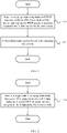
- an embodiment of this application provides a data retransmission method, applied to a target node and including:
- Step 101 Obtain a mapping relationship between GTP-U sequence numbers of N data packets sent by a source node and source PDCP sequence numbers assigned to the N data packets by the source node, where N is an integer greater than or equal to 1, the GTP-U sequence number means GPRS tunnelling protocol user plane sequence number (GPRS Tunnelling Protocol user plane sequence number, GTP-U sequence number, also referred to as GTP-U SN), and the PDCP sequence number means packet data convergence protocol sequence number (Packet Data Convergence Protocol Sequence Number, PDCP sequence number, also referred to as PDCP SN).
- GTP-U sequence number means GPRS tunnelling protocol user plane sequence number (GPRS Tunnelling Protocol user plane sequence number, GTP-U sequence number, also referred to as GTP-U SN)
- the PDCP sequence number means packet data convergence protocol sequence number (Packet Data Convergence Protocol Sequence Number, PDCP sequence number, also referred to as PDCP SN).
- Step 102 Perform data retransmission based on the mapping relationship.
- the source node and the target node are both network nodes that perform multicast transmission in multicast mode, and data loss is likely to occur during handover of a terminal from the source node to the target node.
- the target node performs data retransmission based on the mapping relationship between GTP-U sequence numbers and source PDCP sequence numbers, so as to reduce data loss for the terminal during handover and further meet service requirements of multicast services, resolving the problem of data loss for the terminal during handover.
- step 102 includes: performing data retransmission based on the mapping relationship by using a terminal-dedicated scheduling resource or a temporary scheduling resource.
- the terminal-dedicated scheduling resource may be a wireless resource scheduled through terminal-dedicated scheduling (such as a C-RNTI of the terminal).
- the temporary scheduling resource may be a wireless resource scheduled through temporary scheduling (for example, a temporary G-RNTI assigned by the target node to the terminal, which is scheduling information different from that for transmitting a multicast service in multicast mode by the target node).
- the method before step 102, further includes: obtaining reception status indication information of the terminal for a data packet sent by the source node, where the reception status indication information is used to indicate a source PDCP sequence number of at least one first data packet, and the first data packet is a data packet that has not been received by the terminal before node switching.
- the terminal actively sends a PDCP status report to the target node in a timely manner when or after establishing a connection to the target node, so that the target node can learn the reception status indication information of the terminal; or, the target node requests the terminal to or the source node instructs the terminal to send a PDCP status report to the target node, so as to obtain the reception status indication information of the terminal.
- the target node may determine that a data packet corresponding to a GTP-U SN has not received by the terminal, so as to retransmit data not yet received.
- step 102 includes: performing data transmission based on the source PDCP sequence number of the at least one first data packet and the mapping relationship.
- the performing data transmission based on the source PDCP sequence number of the at least one first data packet and the mapping relationship includes: based on the mapping relationship, performing data retransmission from a first data packet with a smallest PDCP sequence number in the at least one first data packet.
- source PDCP sequence numbers of first data packets reported by the terminal are 3 and 4.
- step 101 includes: receiving status indication information sent by the source node, where the status indication information includes at least one of the following information:
- An occasion of initiating the status indication information by the source node may be when the source node determines to send a handover command to the terminal, or when the source node is sending a handover command to the terminal, or after the source node sends a handover command to the terminal, which is not specifically limited herein.
- the method before step 102, further includes: receiving data packets forwarded by the source node in an order of the GTP-U sequence numbers of the N data packets, where the forwarded data packets may be data buffered by the source node and/or new data obtained from a core-network node.
- a mapping relationship between GTP-U sequence numbers and source PDCP sequence numbers of the data packets can be also provided, where the source PDCP sequence number is a PDCP sequence number assigned to the data packet by the source node.
- the receiving data packets forwarded by the source node in an order of the GTP-U sequence numbers of the N data packets includes:
- step 102 includes:
- the method before step 101, further includes: receiving a handover request message sent by the source node, where the handover request message carries at least one of a multicast service identifier and first indication information indicating that the source node requests to forward multicast service data.
- the multicast service identifier may be a TMGI or a multicast service sequence number (for example, in an Xn interface establishment process, the source node obtains a list of multicast services that can be supported by the target node, and the source node may indicate a corresponding multicast service by using a multicast service sequence number in the list); for example, the first indication information is a DL forwarding IE (downlink forwarding IE), and if the IE is set to a first value, it indicates that the source node requests to forward corresponding multicast service data, or if the IE is set to a second value, it indicates that the source node does not request to forward corresponding multicast service data; for another example, the first indication information is a 1-bit indication, and if the 1-bit value is "1", it indicates that the source node requests to forward corresponding multicast service data, or if the 1-bit value is "0", it indicates that the source node does not request to forward corresponding multicast service data; for still another example, the first indication
- the source node determines, based on a multicast service requirement, whether to request to forward the multicast service data. For example, if a multicast service has a relatively high quality of service QoS requirement (for example, relatively high reliability), the source node adds, to the handover request, the first indication information for requesting to forward the multicast service data; otherwise, the first indication information is not carried.
- a multicast service has a relatively high quality of service QoS requirement (for example, relatively high reliability)
- the source node adds, to the handover request, the first indication information for requesting to forward the multicast service data; otherwise, the first indication information is not carried.
- the method before step 102, further includes: establishing a connection to a terminal that has received a handover command message sent by the source node, where the handover command message carries at least one of the following information:
- the method further includes: based on a cached data status of the target node, sending a data-forwarding stop indication to the source node.
- the method further includes: sending third indication information to a terminal, where the third indication information is used to indicate that data retransmission by the target node has ended.
- the target node in the process of handover of the terminal from one multicast cell to another multicast cell, performs data retransmission based on the mapping relationship between GTP-U sequence numbers and source PDCP sequence numbers of data packets, so as to reduce data loss for the terminal during handover and further meet service requirements of multicast services, resolving the problem of data loss for the terminal during handover.
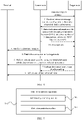
- an embodiment of this application further provides a data retransmission method, applied to a source node and including:
- Step 201 Send, to a target node, a mapping relationship between GTP-U sequence numbers of N data packets and source PDCP sequence numbers assigned to the N data packets by the source node, where N is an integer greater than or equal to 1.
- the GTP-U sequence number means GPRS tunnelling protocol user plane sequence number (GPRS Tunnelling Protocol user plane sequence number, GTP-U sequence number, also referred to as GTP-U SN), and the PDCP sequence number means packet data convergence protocol sequence number (Packet Data Convergence Protocol Sequence Number, PDCP sequence number, also referred to as PDCP SN).
- GTP-U sequence number GPRS Tunnelling Protocol user plane sequence number
- PDCP sequence number means packet data convergence protocol sequence number (Packet Data Convergence Protocol Sequence Number, PDCP sequence number, also referred to as PDCP SN).
- the source node and the target node are both network nodes that perform multicast transmission in multicast mode, and data loss is likely to occur during handover of the terminal from the source node to the target node.
- the target node performs data retransmission based on the mapping relationship between GTP-U sequence numbers and source PDCP sequence numbers, so as to reduce data loss for the terminal during handover and further meet service requirements of multicast services, resolving the problem of data loss for the terminal during handover.
- the data retransmission method provided in this embodiment of this application is executed by a data retransmission apparatus or a control module for loading the data retransmission method in the data retransmission apparatus.
- the data retransmission method provided by the embodiments of this application is described by using the data retransmission method being loaded by the data retransmission apparatus as an example.
- step 201 includes: sending status indication information to the target node, where the status indication information includes at least one of the following information:
- An occasion of initiating the status indication information by the source node may be when the source node determines to send a handover command to the terminal, or when the source node is sending a handover command to the terminal, or after the source node sends a handover command to the terminal, which is not specifically limited herein.
- the method further includes: forwarding data packets in an order of the GTP-U sequence numbers of the N data packets to the target node.
- the forwarded data packets may be data buffered by the source node and/or new data obtained from a core-network node.
- a mapping relationship between GTP-U sequence numbers and source PDCP sequence numbers of the data packets can be also provided, where the source PDCP sequence number is a PDCP sequence number assigned to the data packet by the source node.
- the forwarding data packets in an order of the GTP-U sequence numbers of the N data packets to the target node includes:
- the method before step 201, the method further includes:
- the source node determines, based on a multicast service requirement, whether to request to forward the multicast service data. For example, if a multicast service has a relatively high quality of service QoS requirement (for example, relatively high reliability), the source node adds, to the handover request, the first indication information for requesting to forward the multicast service data; otherwise, the first indication information is not carried.
- a multicast service has a relatively high quality of service QoS requirement (for example, relatively high reliability)
- the source node adds, to the handover request, the first indication information for requesting to forward the multicast service data; otherwise, the first indication information is not carried.
- the method further includes: sending a handover command message to the terminal, where the handover command message carries at least one of the following information:
- the method further includes: stopping data packet forwarding in a case that a first timer expires and the source node has received no data-forwarding stop indication sent by the target node, where the source node maintains a timer (the first timer), and when the timer expires, if no data-forwarding stop indication is received from the target node, the source node automatically stops data forwarding.
- the target node in the process of handover of the terminal from one multicast cell to another multicast cell, performs data retransmission based on the mapping relationship between GTP-U sequence numbers and source PDCP sequence numbers of data packets, so as to reduce data loss for the terminal during handover and further meet service requirements of multicast services, resolving the problem of data loss for the terminal during handover.
- the data retransmission method provided in this embodiment of this application is executed by a data retransmission apparatus or a control module for loading the data retransmission method in the data retransmission apparatus.
- the data retransmission method provided by the embodiments of this application is described by using the data retransmission method being loaded by the data retransmission apparatus as an example.
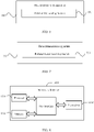
- an embodiment of this application further provides a data retransmission method, applied to a terminal and including: Step 301: After being handed over to a target node, the terminal receives a data packet that is retransmitted by the target node based on a mapping relationship between GTP-U sequence numbers and source PDCP sequence numbers of data packets.
- the source PDCP sequence number of the data packet is a PDCP sequence number assigned to the data packet by a source node.
- the GTP-U sequence number means GPRS tunnelling protocol user plane sequence number (GPRS Tunnelling Protocol user plane sequence number, GTP-U sequence number, also referred to as GTP-U SN), and the PDCP sequence number means packet data convergence protocol sequence number (Packet Data Convergence Protocol Sequence Number, PDCP sequence number, also referred to as PDCP SN).
- GTP-U sequence number GPRS Tunnelling Protocol user plane sequence number
- PDCP sequence number means packet data convergence protocol sequence number (Packet Data Convergence Protocol Sequence Number, PDCP sequence number, also referred to as PDCP SN).
- the terminal maintains two sets of protocol stacks, respectively corresponding to a source MRB (a first protocol stack) and a target MRB (a second protocol stack).
- Data received by the terminal based on a data retransmission configuration corresponds to the protocol stack of the source MRB, and data received based on a common-resource configuration of a target cell corresponds to the protocol stack of the target MRB.
- the terminal when receiving data transmitted by using a C-RNTI, a temporary G-RNTI, or a G-RNTI by a specific HARQ process, the terminal submits the data to the protocol stack corresponding to the source MRB; and when receiving data transmitted by using a G-RNTI by a common HARQ process, the terminal submits the data to the protocol stack corresponding to the target MRB).
- configuration information of common resources for multicast service data transmission in multicast mode in the target cell may be carried in a handover command, or may be obtained by reading system information of the target cell by the terminal after handover to the target cell, or may be sent to the terminal using dedicated signaling in the target cell.
- step 301 includes:
- the terminal can maintain two sets of protocol stacks, that is, the first protocol stack based on the source node and the second protocol stack based on the target node, and can simultaneously receive retransmission data sent by the target node and multicast service data sent by the target node in multicast mode.
- the terminal needs to first cache received data sent by the target node in multicast mode, and the data sent by the target node in multicast mode and cached is delivered to the upper layer only after the terminal receives a data retransmission end indication sent by the target node and delivers data of the first protocol stack to the upper layer.
- the terminal can maintain two sets of protocol stacks, that is, the first protocol stack based on the source node and the second protocol stack based on the target node. After receiving a data retransmission end indication sent by the target node and delivering data of the first protocol stack to the upper layer, the terminal may start to receive, based on the second protocol stack, data sent by the target node in multicast mode.
- step 301 includes: receiving, by using a terminal-dedicated resource or a temporary scheduling resource, the data packet retransmitted by the target node.
- the terminal-dedicated scheduling resource may be a wireless resource scheduled through terminal-dedicated scheduling (such as a C-RNTI of the terminal).
- the temporary scheduling resource may be a wireless resource scheduled through temporary scheduling (for example, a temporary G-RNTI assigned by the target node to the terminal, which is scheduling information different from that for transmitting a multicast service in multicast mode by the target node, such as G-RNTI).
- step 301 the method further includes:
- the method further includes at least one of the following:
- the receiving PDCP entity and the receiving RLC entity that are corresponding to the multicast mode of the multicast service are protocol stack entities used by the terminal for receiving a multicast service sent by the source node in multicast mode.
- the receiving PDCP entity and the receiving RLC entity that are corresponding to the source node are protocol stack entities used when the terminal served by the source node receives data sent by the source node in multicast mode; and after handover, the terminal uses the protocol stack entities to receive retransmission data sent by the target node.
- the terminal may immediately deliver data of the protocol stack entities to the upper layer (which, for example, may be construed as releasing the PDCP entity and the RLC entity), or wait until the timers maintained by the protocol stack entities expire and then deliver data of the protocol stack entities to the upper layer.
- the receiving PDCP entity and the receiving RLC entity that are corresponding to the target node are protocol stack entities used when the terminal served by the target node receives data sent by the target node in multicast mode.
- the method further includes: receiving third indication information sent by the target node, where the third indication information is used to indicate that data retransmission by the target node has ended.
- the method further includes: stopping monitoring a temporary scheduling resource, where the temporary scheduling resource is used for data retransmission by the target node.
- the terminal receiving the data retransmission end indication sent by the target node may be construed as the target node no longer using the temporary scheduling resource for data retransmission.
- the terminal may stop monitoring the temporary scheduling resource, or stop monitoring the temporary scheduling resource when the terminal determines or starts to deliver data of the first protocol stack to the upper layer.
- the method further includes at least one of the following:
- the method before step 301, further includes: sending, to the target node, reception status indication information of the terminal for a data packet sent by the source node, where the reception status indication information is used to indicate a source PDCP sequence number of at least one first data packet, and the first data packet is a data packet that has not been received by the terminal before node switching.
- the terminal actively sends a PDCP status report to the target node in a timely manner when or after establishing a connection to the target node, so that the target node can learn the reception status indication information of the terminal; or, the target node requests the terminal to or the source node instructs the terminal to send a PDCP status report to the target node, so as to obtain the reception status indication information of the terminal.
- the target node may determine that a data packet corresponding to a GTP-U SN has not received by the terminal, so as to retransmit data not yet received.
- step 301 includes: receiving data packets that are retransmitted based on the mapping relationship from a first data packet with a smallest PDCP sequence number in the at least one first data packet.
- source PDCP sequence numbers of first data packets reported by the terminal are 3 and 4.
- the target node in the process of handover of the terminal from one multicast cell to another multicast cell, performs data retransmission based on the mapping relationship between GTP-U sequence numbers and source PDCP sequence numbers of data packets, so as to reduce data loss for the terminal during handover and further meet service requirements of multicast services, resolving the problem of data loss for the terminal during handover.
- the data retransmission method provided in this embodiment of this application is executed by a data retransmission apparatus or a control module for loading the data retransmission method in the data retransmission apparatus.
- the data retransmission method provided by the embodiments of this application is described by using the data retransmission method being loaded by the data retransmission apparatus as an example.
- the data retransmission method includes the following steps.
- Step 1 The source node sends a handover request message to the target node, where the handover request message carries multicast related information and the multicast service information includes one or more of the following contents:
- Step 2 The target node sends a handover response message to the source node, where the handover response message carries multicast service related information, and the multicast service related information includes one or more of the following:
- Step 3 The source node sends status indication information to the target node, where the status indication information is used to indicate a mapping relationship between GTP-U sequence numbers of N data packets and source PDCP sequence numbers, and the status indication information includes at least one of the following information:
- An occasion of initiating the status indication information by the source node may be when the source node determines to send a handover command to the terminal, or when the source node is sending a handover command to the terminal, or after the source node sends a handover command to the terminal, which is not specifically limited herein.
- Step 3.1 The source node forwards data to the target node.
- the source node forwards data to the target node sequentially (GTP-U SN), and the data may be data cached in the source node and/or new data obtained from a core-network node.
- the source node provides the mapping relationship between GTP-U SNs of data packets and source PDCP SNs when forwarding the data to the target node, where the source PDCP SN is a PDCP sequence number assigned to the data packet by the source node.
- the source node starts to sequentially send data packets corresponding to the status indication information of the source node during handover of the terminal; or the source node starts to sequentially send data packets from a next data packet corresponding to the status indication information of the source node during handover of the terminal.
- Step 3 and step 3.1 may be independent processes or a combined process.
- Step 4 The source node sends a handover command message to the terminal, where the handover command message carries multicast service related information, and the multicast service related information includes at least one of the following content:
- Step 5 The terminal receives the handover command message sent by the source node, where the handover command message carries multicast service related information.
- the terminal initiates a connection establishment procedure to the target node.
- the behavior of the terminal includes one or more of the following:
- Step 6 The target node performs data retransmission, where a resource for data retransmission is a wireless resource obtained through terminal-dedicated scheduling (for example, C-RNTI) or temporary scheduling (for example, temporary G-RNTI) by the terminal.
- the terminal maintains two sets of protocol stacks, respectively corresponding to a source MRB (a first protocol stack) and a target MRB (a second protocol stack).
- Data received by the terminal based on a data retransmission configuration corresponds to the protocol stack of the source MRB, and data received based on a common-resource configuration of a target cell corresponds to the protocol stack of the target MRB.
- the terminal when receiving data transmitted by using a C-RNTI, a temporary G-RNTI, or a G-RNTI by a specific HARQ process, the terminal submits the data to the protocol stack corresponding to the source MRB; and when receiving data transmitted by using a G-RNTI by a common HARQ process, the terminal submits the data to the protocol stack corresponding to the target MRB).
- step 7 may be performed before or after step 8.
- the source node maintains a timer. When the timer expires, if no data-forwarding stop indication information is received from the target node, the source node automatically stops data forwarding.
- Step 8 The target node sends, to the terminal, third indication information indicating that data retransmission by the target node has ended.
- the behavior of the terminal further includes one or more of the following:
- the receiving PDCP entity and the receiving RLC entity that are corresponding to the source node are protocol stack entities used when the terminal served by the source node receives data sent by the source node in multicast mode; and after handover, the terminal uses the protocol stack entities to receive retransmission data sent by the target node.
- the terminal may immediately deliver data of the protocol stack entities to the upper layer (which, for example, may be construed as releasing the PDCP entity and the RLC entity), or wait until the timers maintained by the protocol stack entities expire and then deliver data of the protocol stack entities to the upper layer.
- the receiving PDCP entity and the receiving RLC entity that are corresponding to the target node are protocol stack entities used when the terminal served by the target node receives data sent by the target node in multicast mode.
- the terminal stops monitoring the temporary G-RNTI.
- the terminal receiving the data retransmission end indication sent by the target node may be construed as the target node no longer using the temporary scheduling resource for data retransmission.
- the terminal may stop monitoring the temporary scheduling resource, or stop monitoring the temporary scheduling resource when the terminal determines or starts to deliver data of the first protocol stack to the upper layer.
- an embodiment of this application further provides a data retransmission apparatus 500, applied to a target node and including:
- the apparatus includes:
- the first data retransmission submodule includes: a first data retransmission unit, configured to: based on the mapping relationship, perform data retransmission from a first data packet with a smallest PDCP sequence number in the at least one first data packet.
- the relationship obtaining module includes: a relationship obtaining submodule, configured to receive status indication information sent by the source node, where the status indication information includes at least one of the following information:
- the apparatus includes: a data receiving module, configured to receive data packets forwarded by the source node in an order of the GTP-U sequence numbers of the N data packets.
- the data receiving module includes:
- the data retransmission module includes:
- the apparatus includes:
- the apparatus includes: a second connecting module, configured to establish a connection to a terminal that has received a handover command message sent by the source node, where the handover command message carries at least one of the following information:
- the apparatus includes: an indication sending module is configured to: based on a cached data status of the target node, send a data-forwarding stop indication to the source node.
- the apparatus includes: a third sending module, configured to send third indication information to a terminal, where the third indication information is used to indicate that data retransmission by the target node has ended.
- the data retransmission apparatus provided in this embodiment of this application is capable of implementing the processes implemented by the data retransmission apparatus in the method embodiment in FIG. 1 . To avoid repetition, details are not described herein again.
- the target node in the process of handover of the terminal from one multicast cell to another multicast cell, performs data retransmission based on the mapping relationship between GTP-U sequence numbers and source PDCP sequence numbers of data packets, so as to reduce data loss for the terminal during handover and further meet service requirements of multicast services, resolving the problem of data loss for the terminal during handover.
- an embodiment of this application further provides a communications device.
- the communications device is a target node, including a processor, a memory, and a program or an instruction stored in the memory and capable of running on the processor.
- the program or the instruction is executed by the processor, the processes of the foregoing embodiment of the data retransmission method are implemented, with the same technical effects achieved. To avoid repetition, details are not described herein again.
- an embodiment of this application further provides a data retransmission apparatus 600, applied to a source node and including: a relationship sending module 601, configured to send, to a target node, a mapping relationship between GTP-U sequence numbers of N data packets and source PDCP sequence numbers assigned to the N data packets by the source node, where N is an integer greater than or equal to 1.
- the relationship sending module includes: a relationship sending submodule, configured to send status indication information to the target node, where the status indication information includes at least one of the following information:
- the apparatus includes: a data forwarding module, configured to forward data packets in an order of the GTP-U sequence numbers of the N data packets to the target node.
- the data forwarding module includes:
- the apparatus includes:
- the apparatus includes: a command sending module, configured to send a handover command message to a terminal, where the handover command message carries at least one of the following information:
- the apparatus includes:
- the data retransmission apparatus provided in this embodiment of this application is capable of implementing the processes implemented by the data retransmission apparatus in the method embodiment in FIG. 2 . To avoid repetition, details are not described herein again.
- the target node in the process of handover of the terminal from one multicast cell to another multicast cell, performs data retransmission based on the mapping relationship between GTP-U sequence numbers and source PDCP sequence numbers of data packets, so as to reduce data loss for the terminal during handover and further meet service requirements of multicast services, resolving the problem of data loss for the terminal during handover.
- an embodiment of this application further provides a communications device.
- the communications device is a source node, including a processor, a memory, and a program or an instruction stored in the memory and capable of running on the processor.
- the program or the instruction is executed by the processor, the processes of the foregoing embodiment of the data retransmission method are implemented, with the same technical effects achieved. To avoid repetition, details are not described herein again.
- an embodiment of this application further provides a data retransmission apparatus 700, applied to a terminal and including:
- the retransmission receiving module includes: a first submodule, configured to: based on a first protocol stack of the source node, receive the data packet retransmitted by the target node.
- the retransmission receiving module includes: a retransmission receiving submodule, configured to receive, by using a terminal-dedicated resource or a temporary scheduling resource, the data packet retransmitted by the target node.
- the apparatus includes:
- the apparatus further includes at least one of the following modules:
- the apparatus includes: a stop indication receiving module, configured to receive third indication information sent by the target node, where the third indication information is used to indicate that data retransmission by the target node has ended.
- the apparatus includes: a fourth receiving module, configured to: based on a second protocol stack of the target node, receive multicast service data sent by the target node.
- the apparatus further includes at least one of the following modules:
- the data retransmission apparatus provided in this embodiment of this application is capable of implementing the processes implemented by the data retransmission apparatus in the method embodiment in FIG. 3 . To avoid repetition, details are not described herein again.
- the target node in the process of handover of the terminal from one multicast cell to another multicast cell, performs data retransmission based on the mapping relationship between GTP-U sequence numbers and source PDCP sequence numbers of data packets, so as to reduce data loss for the terminal during handover and further meet service requirements of multicast services, resolving the problem of data loss for the terminal during handover.
- an embodiment of this application further provides a communications device.
- the communications device is a terminal, including a processor, a memory, and a program or an instruction stored in the memory and capable of running on the processor.
- the program or the instruction is executed by the processor, the processes of the foregoing embodiment of the data retransmission method are implemented, with the same technical effects achieved. To avoid repetition, details are not described herein again.
- the data retransmission apparatus in this embodiment of this application may be an apparatus, or may be a component, an integrated circuit, or a chip in the terminal.
- the apparatus may be a mobile electronic device or a non-mobile electronic device.
- the mobile electronic device may be a mobile phone, a tablet computer, a notebook computer, a palmtop computer, an in-vehicle electronic device, a wearable device, an ultra-mobile personal computer (ultra-mobile personal computer, UMPC), a netbook, a personal digital assistant (personal digital assistant, PDA), or the like.
- the non-mobile electronic device may be a server, a network-attached storage (Network Attached Storage, NAS), a personal computer (personal computer, PC), a television (television, TV), a teller machine, a self-service machine, or the like. This is not specifically limited in the embodiments of this application.
- the data retransmission apparatus in this embodiment of this application may be an apparatus having an operating system.
- the operating system may be the Android (Android) operating system, the iOS operating system, or other possible operating systems, which is not specifically limited in the embodiments of this application.
- FIG. 8 is a structural diagram of a network-side device (target node or source node) according to an embodiment of this application, and the network-side device is capable of implementing details of the information receiving method described above, with the same effects achieved.
- the network-side device 1300 includes a processor 1301, a transceiver 1302, a memory 1303, and a bus interface.
- the processor 1301 is configured to read a program in the memory 1303 to perform the following processes:
- the processor 1301 is configured to read a program in the memory 1303 to perform the following process: sending, to a target node, a mapping relationship between GTP-U sequence numbers of N data packets and source PDCP sequence numbers assigned to the N data packets by the source node, where N is an integer greater than or equal to 1.
- the target node in the process of handover of the terminal from one multicast cell to another multicast cell, performs data retransmission based on the mapping relationship between GTP-U sequence numbers and source PDCP sequence numbers of data packets, so as to reduce data loss for the terminal during handover and further meet service requirements of multicast services, resolving the problem of data loss for the terminal during handover.
- a bus architecture may include any quantity of interconnected buses and bridges, specifically for interconnecting various circuits of one or more processors represented by the processor 1301 and a memory represented by the memory 1303.
- the bus architecture may further interconnect various other circuits such as a peripheral device, a voltage regulator, and a power management circuit. These are all well known in the art, and therefore are not further described in this specification.
- the bus interface provides an interface.
- the transceiver 1302 may be a plurality of components, that is, the transceiver 1302 includes a transmitter and a receiver, and provides a unit for communicating with various other apparatuses on a transmission medium.
- FIG. 9 is a schematic diagram of a hardware structure of an electronic device for implementing the embodiments of this application.
- the electronic device 900 includes but is not limited to components such as a radio frequency unit 901, a network module 902, an audio output unit 903, an input unit 904, a sensor 905, a display unit 906, a user input unit 907, an interface unit 908, a memory 909, and a processor 910.
- the electronic device 900 may further include a power supply (for example, a battery) supplying power to all components, and the power supply may be logically connected to the processor 910 through a power management system. In this way, functions such as charge management, discharge management, and power consumption management are implemented by using the power management system.
- a power supply for example, a battery
- functions such as charge management, discharge management, and power consumption management are implemented by using the power management system.
- the structure of the electronic device shown in FIG. 9 does not constitute any limitation on the electronic device.
- the electronic device may include more or fewer components than those shown in the figure, or a combination of some components, or the components disposed differently. Details are not described herein.
- the radio frequency unit 901 is configured to: after the terminal is handed over to a target node, receive a data packet that is retransmitted by the target node based on a mapping relationship between GTP-U sequence numbers and source PDCP sequence numbers of data packets; where the source PDCP sequence number of the data packet is a PDCP sequence number assigned to the data packet by a source node.
- the target node in the process of handover of the terminal from one multicast cell to another multicast cell, performs data retransmission based on the mapping relationship between GTP-U sequence numbers and source PDCP sequence numbers of data packets, so as to reduce data loss for the terminal during handover and further meet service requirements of multicast services, resolving the problem of data loss for the terminal during handover.
- the radio frequency unit 901 may be configured to receive and send information, or to receive and send a signal in a call process, and specially, after receiving downlink data from a base station, send the downlink data to the processor 910 for processing; and also send uplink data to the base station.
- the radio frequency unit 901 includes but is not limited to an antenna, at least one amplifier, a transceiver, a coupler, a low noise amplifier, a duplexer, and the like.
- the radio frequency unit 901 may also communicate with a network and other devices via a wireless communications system.
- the electronic device provides a user with wireless broadband internet access through the network module 902, for example, helping the user to transmit and receive e-mails, browse web pages, and access streaming media.
- the audio output unit 903 may convert audio data received by the radio frequency unit 901 or the network module 902 or stored in the memory 909 into an audio signal and output the audio signal as a sound. Furthermore, the audio output unit 903 may also provide audio output (for example, a call signal received sound or a message received sound) related to a specific function performed by the electronic device 900.
- the audio output unit 903 includes a speaker, a buzzer, a receiver, and the like.
- the input unit 904 is configured to receive an audio or video signal.
- the input unit 904 may include a graphics processing unit (Graphics Processing Unit, GPU) 9041 and a microphone 9042.
- the graphics processing unit 9041 processes image data of a still picture or a video obtained by an image capture apparatus (for example, a camera) in an image capture mode or a video capture mode.
- a processed image frame may be displayed on the display unit 906.
- the image frame processed by the graphics processing unit 9041 may be stored in the memory 909 (or another storage medium) or be transmitted by the radio frequency unit 901 or the network module 902.
- the microphone 9042 is capable of receiving sounds and processing such sounds into audio data.
- the processed audio data may be converted in a telephone call mode into a format that can be transmitted by the radio frequency unit 901 to a mobile communications base station, for outputting.
- the electronic device 900 may further include at least one sensor 905, for example, an optical sensor, a motion sensor, and other sensors.
- the optical sensor may include an ambient light sensor and a proximity sensor.
- the ambient light sensor may adjust luminance of the display panel 9061 based on brightness of ambient light
- the proximity sensor may turn off the display panel 9061 and/or backlight when the electronic device 900 moves close to an ear.
- an accelerometer sensor can detect magnitudes of accelerations in all directions (usually three axes), can detect a magnitude and a direction of gravity when the electronic device is in a static state, and can be applied to posture recognition (such as screen switching between portrait and landscape, related games, and magnetometer posture calibration) of the electronic device, functions related to vibration recognition (such as pedometer and tapping), and the like.
- the sensor 905 may also include a fingerprint sensor, a pressure sensor, an iris sensor, a molecular sensor, a gyroscope, a barometer, a hygrometer, a thermometer, an infrared sensor, and the like. Details are not described herein.
- the display unit 906 is configured to display information input by the user or information provided to the user.
- the display unit 906 may include the display panel 9061.
- the display panel 9061 may be configured in a form of a liquid crystal display (Liquid Crystal Display, LCD), an organic light-emitting diode (Organic Light-Emitting Diode, OLED), or the like.
- the user input unit 907 may be configured to receive input digit or character information and generate key signal input related to user setting and function control of the user equipment.
- the user input unit 907 may include a touch panel 9071 and other input devices 9072.
- the touch panel 9071 is also referred to as a touchscreen and can collect a touch operation (such as an operation performed by the user on the touch panel 9071 or near the touch panel 9071 with a finger or by using any proper object or accessory such as a stylus) of the user on or near the touch panel 9071.
- the touch panel 9071 may include two parts: a touch detection apparatus and a touch controller.
- the touch detection apparatus detects a touch azimuth of a user, detects a signal brought by a touch operation, and transmits the signal to the touch controller.
- the touch controller receives touch information from the touch detection apparatus, converts the touch information into touchpoint coordinates, and transmits the touchpoint coordinates to the processor 910, and can receive a command transmitted by the processor 910 and execute the command.
- the touch panel 9071 may be implemented in a plurality of forms, for example, as a resistive, capacitive, infrared, or surface acoustic wave touch panel.
- the user input unit 907 may further include the other input devices 9072 in addition to the touch panel 9071.
- the other input devices 9072 may include but are not limited to a physical keyboard, a function key (such as a volume control key or an on/off key), a trackball, a mouse, and a joystick. Details are not described herein.
- the touch panel 9071 may cover the display panel 9061.
- the touch panel 9071 transmits the touch operation to the processor 910 to determine a type of a touch event. Then, the processor 910 provides a corresponding visual output on the display panel 9061 based on the type of the touch event.
- the touch panel 9071 and the display panel 9061 act as two independent parts to implement input and output functions of the electronic device, in some embodiments, the touch panel 9071 and the display panel 9061 may be integrated to implement the input and output functions of the electronic device. This is not specifically limited herein.
- the interface unit 908 is an interface between an external apparatus and the electronic device 900.
- the external apparatus may include a wired or wireless headphone port, an external power (or battery charger) port, a wired or wireless data port, a memory card port, a port for connecting an apparatus provided with a recognition module, an audio input/output (I/O) port, a video I/O port, an earphone port, and the like.
- the interface unit 908 may be configured to: receive input (for example, data information and power) from the external apparatus, and transmit the received input to one or more elements in the electronic device 900, or may be configured to transmit data between the electronic device 900 and the external apparatus.
- the memory 909 may be configured to store software programs and various data.
- the memory 909 may mainly include a program storage area and a data storage area.
- the program storage area may store an operating system, and an application program required by at least one function (for example, a sound playback function or an image playback function).
- the data storage area may store data (for example, audio data or a phone book) created according to use of the mobile phone.
- the memory 909 may include a high-speed random access memory, and may further include a non-volatile memory such as at least one disk storage device, a flash memory device, or another volatile solid-state storage device.
- the processor 910 is a control center of the electronic device, and is connected to all components of the electronic device by using various interfaces and lines. By running or executing a software program and/or module that is stored in the memory 909 and calling data stored in the memory 909, the processor 910 executes various functions of the electronic device and processes data, so as to perform overall monitoring on the electronic device.
- the processor 910 may include one or more processing units.
- the processor 910 may integrate an application processor and a modem processor.
- the application processor mainly processes the operating system, a user interface, an application program, and the like.
- the modem processor mainly processes wireless communication. It can be understood that the modem processor may alternatively be not integrated in the processor 910.
- the electronic device 900 may further include the power supply (such as a battery) for supplying power to the components.
- the power supply may be logically connected to the processor 910 through a power management system. In this way, functions such as charge management, discharge management, and power consumption management are implemented by using the power management system.
- the electronic device 900 includes some functional modules that are not shown, details of which are not described herein.
- An embodiment of the present invention further provides a readable storage medium, where a program or an instruction is stored in the readable storage medium.
- a program or an instruction is stored in the readable storage medium.
- the processor is a processor in the electronic device described in the foregoing embodiment.
- the readable storage medium includes a computer-readable storage medium, for example, a computer read-only memory (Read-Only Memory, ROM), a random access memory (Random Access Memory, RAM), a magnetic disk, or an optical disc.
- An embodiment of this application further provides a chip, where the chip includes a processor and a communications interface, the communications interface is coupled to the processor, and the processor is configured to run a program or an instruction to implement the foregoing data retransmission method embodiments, with the same technical effects achieved. To avoid repetition, details are not repeated herein.
- the chip mentioned in this embodiment of this application may also be referred to as a system-on-chip, a system chip, a system-on-a-chip, a system on a chip, or the like.
- An embodiment of this application further provides an electronic device, configured to perform the processes of the foregoing data retransmission method embodiment, with the same technical effects achieved. To avoid repetition, details are not described herein.
- An embodiment of this application further provides a data retransmission apparatus, configured to perform the processes of the foregoing data retransmission method embodiment, with the same technical effects achieved. To avoid repetition, details are not described herein.
- An embodiment of this application further provides a computer program product, and the computer program product is executed by at least one processor to perform the processes of the foregoing data retransmission method embodiment, with the same technical effects achieved. To avoid repetition, details are not described herein.
- execution of the functions is not limited to the order shown or described, and the functions may alternatively be executed in a substantially simultaneous manner or in a reverse order.
- the described method may be performed in an order different from that described, and steps may be added, omitted, or combined.
- features described with reference to some examples may be combined in other examples.
- the method in the foregoing embodiments may be implemented by software in addition to a necessary universal hardware platform or by hardware only. In most cases, the former is a more preferred implementation.
- the technical solutions of this application essentially or the part contributing to the prior art may be implemented in a form of a software product.
- the software product is stored in a storage medium (such as a ROM/RAM, a magnetic disk, or an optical disc), and includes several instructions for instructing a terminal (which may be a mobile phone, a computer, a server, an air conditioner, a network device, or the like) to perform the methods described in the embodiments of this application.
Landscapes
- Engineering & Computer Science (AREA)
- Computer Networks & Wireless Communication (AREA)
- Signal Processing (AREA)
- Multimedia (AREA)
- Mobile Radio Communication Systems (AREA)
Applications Claiming Priority (2)
| Application Number | Priority Date | Filing Date | Title |
|---|---|---|---|
| CN202010367115.XA CN113596736B (zh) | 2020-04-30 | 2020-04-30 | 数据重传方法、装置、目标节点、源节点及终端 |
| PCT/CN2021/089120 WO2021218788A1 (zh) | 2020-04-30 | 2021-04-23 | 数据重传方法、装置、目标节点、源节点及终端 |
Publications (2)
| Publication Number | Publication Date |
|---|---|
| EP4124080A1 true EP4124080A1 (de) | 2023-01-25 |
| EP4124080A4 EP4124080A4 (de) | 2023-08-30 |
Family
ID=78237614
Family Applications (1)
| Application Number | Title | Priority Date | Filing Date |
|---|---|---|---|
| EP21795959.2A Pending EP4124080A4 (de) | 2020-04-30 | 2021-04-23 | Datenneuübertragungsverfahren und -vorrichtung, zielknoten, quellknoten und endgerät |
Country Status (6)
| Country | Link |
|---|---|
| US (2) | US12395271B2 (de) |
| EP (1) | EP4124080A4 (de) |
| JP (1) | JP7392176B2 (de) |
| KR (1) | KR20230004786A (de) |
| CN (1) | CN113596736B (de) |
| WO (1) | WO2021218788A1 (de) |
Families Citing this family (5)
| Publication number | Priority date | Publication date | Assignee | Title |
|---|---|---|---|---|
| JP2023126994A (ja) * | 2020-08-04 | 2023-09-13 | シャープ株式会社 | 端末装置、基地局装置、方法、および、集積回路 |
| WO2023102898A1 (zh) * | 2021-12-10 | 2023-06-15 | Oppo广东移动通信有限公司 | 重传方式的确定方法及定时器的控制方法、装置 |
| CN114285806B (zh) * | 2021-12-24 | 2024-09-13 | 上海交通大学 | 一种收发数据的方法及其装置 |
| CN121890221A (zh) * | 2023-09-22 | 2026-04-17 | 中兴通讯股份有限公司 | 用于harq信息传输的方法、设备和系统 |
| CN117318898B (zh) * | 2023-11-24 | 2024-02-09 | 合肥奎芯集成电路设计有限公司 | 高速串行接口中重复数据包的处理方法 |
Family Cites Families (13)
| Publication number | Priority date | Publication date | Assignee | Title |
|---|---|---|---|---|
| CN101400156B (zh) * | 2007-09-29 | 2012-06-06 | 华为技术有限公司 | 基于s1切换的下行及上行数据包转发方法 |
| US8477719B2 (en) | 2007-10-01 | 2013-07-02 | Qualcomm Incorporated | Systems and methods for in-order delivery in downlink during handover |
| CN103533586B (zh) * | 2012-07-03 | 2016-07-20 | 电信科学技术研究院 | 切换过程中的信令交互及层重建的方法和设备 |
| CN108551681B (zh) * | 2012-11-29 | 2022-01-14 | 华为技术有限公司 | 一种数据传输的控制方法、装置及系统 |
| US20160066222A1 (en) | 2014-09-02 | 2016-03-03 | Nokia Solutions And Networks Oy | Multi-connectivity in a wireless network |
| BR112017016834A2 (pt) | 2015-02-05 | 2018-06-26 | Huawei Tech Co Ltd | método e aparelho de transmissão de dados de serviço |
| CN107925905B (zh) * | 2015-08-19 | 2021-09-28 | 三星电子株式会社 | 用于处理向wlan载波卸载drb的方法和无线通信系统 |
| US10728812B2 (en) * | 2016-08-11 | 2020-07-28 | Lg Electronics Inc. | Method and apparatus for supporting MBMS service continuity |
| CN110475299B (zh) * | 2018-05-10 | 2021-06-29 | 维沃移动通信有限公司 | 一种切换小区的方法及装置 |
| CN110620640B (zh) * | 2018-06-19 | 2021-09-21 | 维沃移动通信有限公司 | 一种数据传输方法、终端及节点设备 |
| CN111586769B (zh) * | 2019-02-15 | 2021-10-15 | 华为技术有限公司 | 无线通信系统中的切换方法、装置及系统 |
| KR102160005B1 (ko) * | 2019-04-18 | 2020-09-25 | 한국전자통신연구원 | 이동통신 시스템에서 핸드오버 동안의 저지연 데이터 전송 방법 및 이를 위한 장치 |
| CN114631354B (zh) * | 2019-10-30 | 2024-05-17 | 中兴通讯股份有限公司 | 减少切换场景中的服务中断 |
-
2020
- 2020-04-30 CN CN202010367115.XA patent/CN113596736B/zh active Active
-
2021
- 2021-04-23 EP EP21795959.2A patent/EP4124080A4/de active Pending
- 2021-04-23 KR KR1020227041248A patent/KR20230004786A/ko not_active Ceased
- 2021-04-23 WO PCT/CN2021/089120 patent/WO2021218788A1/zh not_active Ceased
- 2021-04-23 JP JP2022566295A patent/JP7392176B2/ja active Active
-
2022
- 2022-10-18 US US17/968,665 patent/US12395271B2/en active Active
-
2025
- 2025-05-30 US US19/223,689 patent/US20250293807A1/en active Pending
Also Published As
| Publication number | Publication date |
|---|---|
| US20250293807A1 (en) | 2025-09-18 |
| CN113596736B (zh) | 2022-09-02 |
| WO2021218788A1 (zh) | 2021-11-04 |
| US12395271B2 (en) | 2025-08-19 |
| JP2023523816A (ja) | 2023-06-07 |
| JP7392176B2 (ja) | 2023-12-05 |
| KR20230004786A (ko) | 2023-01-06 |
| CN113596736A (zh) | 2021-11-02 |
| US20230039646A1 (en) | 2023-02-09 |
| EP4124080A4 (de) | 2023-08-30 |
Similar Documents
| Publication | Publication Date | Title |
|---|---|---|
| US12395271B2 (en) | Data retransmission method, data retransmission apparatus, target node, source node, and terminal | |
| US12414016B2 (en) | Mobility management method, source base station, target base station, and terminal device | |
| US12452632B2 (en) | Bearer establishment method, configuration method, terminal, and network side device | |
| CN111278165B (zh) | 连接建立方法、终端设备及网络设备 | |
| CN112770409B (zh) | 无线链路失败处理方法及装置 | |
| US12193033B2 (en) | Multimedia broadcast multicast service configuration method, terminal, and network-side device | |
| CN111615196A (zh) | 资源配置方法、数据的接收方法及相关设备 | |
| WO2021052435A1 (zh) | 数据传输方法、终端及网络节点 | |
| WO2021136473A1 (zh) | 多播业务的传输方法、传输处理方法及相关设备 | |
| WO2021218848A1 (zh) | 数据重传方法、装置、目标节点、源节点及终端 | |
| JP2021531704A (ja) | ランダムアクセス方法、端末装置及びネットワーク装置 | |
| CN111436026B (zh) | 副链路组播通信的配置方法和终端 | |
| CN111614443A (zh) | 终端能力上报、信息接收方法、终端及网络设备 | |
| CN113938968B (zh) | 数据传输方法、装置及设备 | |
| CN112787767B (zh) | 数据传输方法、设备及介质 | |
| CN110475285B (zh) | 一种操作方法及终端 | |
| CN113556781B (zh) | 数据接收、信息配置方法、终端及网络设备 |
Legal Events
| Date | Code | Title | Description |
|---|---|---|---|
| STAA | Information on the status of an ep patent application or granted ep patent |
Free format text: STATUS: THE INTERNATIONAL PUBLICATION HAS BEEN MADE |
|
| PUAI | Public reference made under article 153(3) epc to a published international application that has entered the european phase |
Free format text: ORIGINAL CODE: 0009012 |
|
| STAA | Information on the status of an ep patent application or granted ep patent |
Free format text: STATUS: REQUEST FOR EXAMINATION WAS MADE |
|
| 17P | Request for examination filed |
Effective date: 20221018 |
|
| AK | Designated contracting states |
Kind code of ref document: A1 Designated state(s): AL AT BE BG CH CY CZ DE DK EE ES FI FR GB GR HR HU IE IS IT LI LT LU LV MC MK MT NL NO PL PT RO RS SE SI SK SM TR |
|
| DAV | Request for validation of the european patent (deleted) | ||
| DAX | Request for extension of the european patent (deleted) | ||
| A4 | Supplementary search report drawn up and despatched |
Effective date: 20230728 |
|
| RIC1 | Information provided on ipc code assigned before grant |
Ipc: H04L 1/1822 20230101ALI20230724BHEP Ipc: H04L 1/08 20060101ALI20230724BHEP Ipc: H04W 36/02 20090101ALI20230724BHEP Ipc: H04W 36/16 20090101ALI20230724BHEP Ipc: H04W 4/06 20090101AFI20230724BHEP |