EP4123804A1 - Battery pack assembly system and battery pack assembly method using same - Google Patents
Battery pack assembly system and battery pack assembly method using same Download PDFInfo
- Publication number
- EP4123804A1 EP4123804A1 EP21864605.7A EP21864605A EP4123804A1 EP 4123804 A1 EP4123804 A1 EP 4123804A1 EP 21864605 A EP21864605 A EP 21864605A EP 4123804 A1 EP4123804 A1 EP 4123804A1
- Authority
- EP
- European Patent Office
- Prior art keywords
- battery pack
- battery cells
- battery
- plasma
- pack assembly
- Prior art date
- Legal status (The legal status is an assumption and is not a legal conclusion. Google has not performed a legal analysis and makes no representation as to the accuracy of the status listed.)
- Granted
Links
Images



Classifications
-
- H—ELECTRICITY
- H01—ELECTRIC ELEMENTS
- H01M—PROCESSES OR MEANS, e.g. BATTERIES, FOR THE DIRECT CONVERSION OF CHEMICAL ENERGY INTO ELECTRICAL ENERGY
- H01M50/00—Constructional details or processes of manufacture of the non-active parts of electrochemical cells other than fuel cells, e.g. hybrid cells
- H01M50/20—Mountings; Secondary casings or frames; Racks, modules or packs; Suspension devices; Shock absorbers; Transport or carrying devices; Holders
- H01M50/244—Secondary casings; Racks; Suspension devices; Carrying devices; Holders characterised by their mounting method
-
- B—PERFORMING OPERATIONS; TRANSPORTING
- B25—HAND TOOLS; PORTABLE POWER-DRIVEN TOOLS; MANIPULATORS
- B25J—MANIPULATORS; CHAMBERS PROVIDED WITH MANIPULATION DEVICES
- B25J11/00—Manipulators not otherwise provided for
-
- H—ELECTRICITY
- H01—ELECTRIC ELEMENTS
- H01M—PROCESSES OR MEANS, e.g. BATTERIES, FOR THE DIRECT CONVERSION OF CHEMICAL ENERGY INTO ELECTRICAL ENERGY
- H01M50/00—Constructional details or processes of manufacture of the non-active parts of electrochemical cells other than fuel cells, e.g. hybrid cells
- H01M50/20—Mountings; Secondary casings or frames; Racks, modules or packs; Suspension devices; Shock absorbers; Transport or carrying devices; Holders
-
- B—PERFORMING OPERATIONS; TRANSPORTING
- B05—SPRAYING OR ATOMISING IN GENERAL; APPLYING FLUENT MATERIALS TO SURFACES, IN GENERAL
- B05D—PROCESSES FOR APPLYING FLUENT MATERIALS TO SURFACES, IN GENERAL
- B05D3/00—Pretreatment of surfaces to which liquids or other fluent materials are to be applied; After-treatment of applied coatings, e.g. intermediate treating of an applied coating preparatory to subsequent applications of liquids or other fluent materials
- B05D3/14—Pretreatment of surfaces to which liquids or other fluent materials are to be applied; After-treatment of applied coatings, e.g. intermediate treating of an applied coating preparatory to subsequent applications of liquids or other fluent materials by electrical means
-
- B—PERFORMING OPERATIONS; TRANSPORTING
- B05—SPRAYING OR ATOMISING IN GENERAL; APPLYING FLUENT MATERIALS TO SURFACES, IN GENERAL
- B05D—PROCESSES FOR APPLYING FLUENT MATERIALS TO SURFACES, IN GENERAL
- B05D3/00—Pretreatment of surfaces to which liquids or other fluent materials are to be applied; After-treatment of applied coatings, e.g. intermediate treating of an applied coating preparatory to subsequent applications of liquids or other fluent materials
- B05D3/14—Pretreatment of surfaces to which liquids or other fluent materials are to be applied; After-treatment of applied coatings, e.g. intermediate treating of an applied coating preparatory to subsequent applications of liquids or other fluent materials by electrical means
- B05D3/141—Plasma treatment
- B05D3/145—After-treatment
-
- B—PERFORMING OPERATIONS; TRANSPORTING
- B25—HAND TOOLS; PORTABLE POWER-DRIVEN TOOLS; MANIPULATORS
- B25J—MANIPULATORS; CHAMBERS PROVIDED WITH MANIPULATION DEVICES
- B25J15/00—Gripping heads and other end effectors
- B25J15/08—Gripping heads and other end effectors having finger members
-
- B—PERFORMING OPERATIONS; TRANSPORTING
- B25—HAND TOOLS; PORTABLE POWER-DRIVEN TOOLS; MANIPULATORS
- B25J—MANIPULATORS; CHAMBERS PROVIDED WITH MANIPULATION DEVICES
- B25J9/00—Program-controlled manipulators
- B25J9/02—Program-controlled manipulators characterised by movement of the arms, e.g. cartesian coordinate type
- B25J9/04—Program-controlled manipulators characterised by movement of the arms, e.g. cartesian coordinate type by rotating at least one arm, excluding the head movement itself, e.g. cylindrical coordinate type or polar coordinate type
-
- B—PERFORMING OPERATIONS; TRANSPORTING
- B25—HAND TOOLS; PORTABLE POWER-DRIVEN TOOLS; MANIPULATORS
- B25J—MANIPULATORS; CHAMBERS PROVIDED WITH MANIPULATION DEVICES
- B25J9/00—Program-controlled manipulators
- B25J9/02—Program-controlled manipulators characterised by movement of the arms, e.g. cartesian coordinate type
- B25J9/04—Program-controlled manipulators characterised by movement of the arms, e.g. cartesian coordinate type by rotating at least one arm, excluding the head movement itself, e.g. cylindrical coordinate type or polar coordinate type
- B25J9/046—Revolute coordinate type
-
- H—ELECTRICITY
- H01—ELECTRIC ELEMENTS
- H01M—PROCESSES OR MEANS, e.g. BATTERIES, FOR THE DIRECT CONVERSION OF CHEMICAL ENERGY INTO ELECTRICAL ENERGY
- H01M10/00—Secondary cells; Manufacture thereof
- H01M10/04—Construction or manufacture in general
- H01M10/0404—Machines for assembling batteries
-
- H—ELECTRICITY
- H01—ELECTRIC ELEMENTS
- H01M—PROCESSES OR MEANS, e.g. BATTERIES, FOR THE DIRECT CONVERSION OF CHEMICAL ENERGY INTO ELECTRICAL ENERGY
- H01M10/00—Secondary cells; Manufacture thereof
- H01M10/60—Heating or cooling; Temperature control
- H01M10/65—Means for temperature control structurally associated with the cells
- H01M10/655—Solid structures for heat exchange or heat conduction
- H01M10/6551—Surfaces specially adapted for heat dissipation or radiation, e.g. fins or coatings
-
- H—ELECTRICITY
- H01—ELECTRIC ELEMENTS
- H01M—PROCESSES OR MEANS, e.g. BATTERIES, FOR THE DIRECT CONVERSION OF CHEMICAL ENERGY INTO ELECTRICAL ENERGY
- H01M10/00—Secondary cells; Manufacture thereof
- H01M10/60—Heating or cooling; Temperature control
- H01M10/65—Means for temperature control structurally associated with the cells
- H01M10/655—Solid structures for heat exchange or heat conduction
- H01M10/6554—Rods or plates
-
- H—ELECTRICITY
- H01—ELECTRIC ELEMENTS
- H01M—PROCESSES OR MEANS, e.g. BATTERIES, FOR THE DIRECT CONVERSION OF CHEMICAL ENERGY INTO ELECTRICAL ENERGY
- H01M10/00—Secondary cells; Manufacture thereof
- H01M10/60—Heating or cooling; Temperature control
- H01M10/65—Means for temperature control structurally associated with the cells
- H01M10/655—Solid structures for heat exchange or heat conduction
- H01M10/6556—Solid parts with flow channel passages or pipes for heat exchange
-
- H—ELECTRICITY
- H01—ELECTRIC ELEMENTS
- H01M—PROCESSES OR MEANS, e.g. BATTERIES, FOR THE DIRECT CONVERSION OF CHEMICAL ENERGY INTO ELECTRICAL ENERGY
- H01M50/00—Constructional details or processes of manufacture of the non-active parts of electrochemical cells other than fuel cells, e.g. hybrid cells
- H01M50/20—Mountings; Secondary casings or frames; Racks, modules or packs; Suspension devices; Shock absorbers; Transport or carrying devices; Holders
- H01M50/204—Racks, modules or packs for multiple batteries or multiple cells
- H01M50/207—Racks, modules or packs for multiple batteries or multiple cells characterised by their shape
- H01M50/213—Racks, modules or packs for multiple batteries or multiple cells characterised by their shape adapted for cells having curved cross-section, e.g. round or elliptic
-
- H—ELECTRICITY
- H01—ELECTRIC ELEMENTS
- H01M—PROCESSES OR MEANS, e.g. BATTERIES, FOR THE DIRECT CONVERSION OF CHEMICAL ENERGY INTO ELECTRICAL ENERGY
- H01M10/00—Secondary cells; Manufacture thereof
- H01M10/04—Construction or manufacture in general
-
- Y—GENERAL TAGGING OF NEW TECHNOLOGICAL DEVELOPMENTS; GENERAL TAGGING OF CROSS-SECTIONAL TECHNOLOGIES SPANNING OVER SEVERAL SECTIONS OF THE IPC; TECHNICAL SUBJECTS COVERED BY FORMER USPC CROSS-REFERENCE ART COLLECTIONS [XRACs] AND DIGESTS
- Y02—TECHNOLOGIES OR APPLICATIONS FOR MITIGATION OR ADAPTATION AGAINST CLIMATE CHANGE
- Y02E—REDUCTION OF GREENHOUSE GAS [GHG] EMISSIONS, RELATED TO ENERGY GENERATION, TRANSMISSION OR DISTRIBUTION
- Y02E60/00—Enabling technologies; Technologies with a potential or indirect contribution to GHG emissions mitigation
- Y02E60/10—Energy storage using batteries
Definitions
- the present invention relates to a battery pack assembly system and a battery pack assembly method using the same, and more particularly to a battery pack assembly system that performs plasma treatment in order to increase force of coupling between a battery pack and a heat sink and a battery pack assembly method using the same.
- a secondary battery which is capable of being repeatedly charged and discharged, has an advantage in that lifespan of a battery cell is long, and is used in a form in which the secondary battery is detachably attached to a device or is built in a device.
- the kinds of devices using the secondary battery as an energy source have increased.
- a lithium secondary battery which is charged and discharged as the result of movement of lithium ions, has been used not only in the field of a small-sized battery cell, which is used for mobile devices or small-sized electronic products, but also in the field of a medium- or large-sized battery pack, which is used as an energy source of an electric vehicle or a power storage system that requires high output and high voltage, since the lithium secondary battery has advantages of high energy density and discharge voltage.
- the lithium secondary battery is classified as a cylindrical secondary battery having an electrode assembly mounted in a cylindrical metal can, a prismatic secondary battery having an electrode assembly mounted in a prismatic metal can, or a pouch-shaped secondary battery having an electrode assembly mounted in a pouch-shaped case made of an aluminum laminate sheet.
- the cylindrical secondary battery has advantages in that the capacity of the cylindrical secondary battery is relatively large and in that the cylindrical secondary battery is structurally stable.
- a process of disposing a plurality of cylindrical battery cells in a battery pack case in a compact state, adding a heat dissipation member, such as a heat sink, and hermetically sealing the battery pack case may be performed.
- an adhesive is applied therebetween.
- surfaces of the heat sink and the battery cells at which the heat sink and the battery cells are adhered to each other may be treated with plasma.
- FIG. 1 is a perspective view showing a process of treating the bottom surfaces of conventional cylindrical battery cells with plasma.
- a battery pack case 100 includes an upper case 110 and a lower case 120, and a plurality of battery cells 200 is disposed in the battery pack case 100 at predetermined intervals.
- a frame 130 configured to stably fix the battery cells 200 may be added to the interior of each of the upper case 110 and the lower case 120.
- the plurality of battery cells 200 is disposed such that the upper surfaces 201 thereof face upwards in the state in which the upper case 110 and the lower case 120 are coupled to each other.
- a battery pack is rotated 180 degrees based on an x-axis, and then the lower case 120 is removed such that the lower surfaces 202 of the plurality of battery cells 200 are exposed.
- the lower surfaces 202 of the plurality of battery cells 200 are treated with plasma, the lower case 120 is added again, and the battery pack is rotated 180 degrees based on the x-axis so as to be returned to the original state thereof.
- a plasma treatment effect greatly varies depending on the distance between a target and a plasma device. For this reason, it is necessary to maintain a uniform distance. In the above process, however, it is difficult to maintain a uniform distance between the target and the plasma device.
- the present invention has been made in view of the above problems, and it is an object of the present invention to provide a battery pack assembly system configured such that bottoms of a plurality of battery cells are treated with plasma in the state in which the plurality of battery cells is aligned so as to be disposed side by side, whereby a plasma treatment effect for the plurality of battery cells is consistently and excellently exhibited, and a battery pack assembly method using the same.
- a battery pack assembly system includes a battery cell supply unit configured to supply a plurality of battery cells in an aligned state, a robot arm configured to move the plurality of battery cells, a plasma treatment unit configured to treat the plurality of battery cells with plasma, and an assembly unit in which a battery pack case configured to receive the plurality of battery cells therein is disposed.
- the battery pack assembly system according to the present invention may further include a heat sink disposed in the battery pack case.
- an adhesive may be applied to a first surface of the heat sink.
- the adhesive may be applied to the first surface of the heat sink on the first surface of the heat sink which is treated with the plasma.
- the robot arm may be controlled such that a plasma treatment is performed as the plurality of battery cells are disposed above the plasma treatment unit and spaced apart from the plasma treatment unit by a predetermined distance.
- the predetermined distance may be 1 mm.
- the plasma treatment unit may be disposed between the battery cell supply unit and the assembly unit.
- the robot arm may include a gripper configured to hold or release the plurality of battery cells.
- a frame member may be mounted in the battery pack case, and the plurality of battery cells may be disposed at the frame member.
- the present invention provides a battery pack assembly method using the battery pack assembly system.
- the battery pack assembly method includes (a) aligning the plurality of battery cells in the battery cell supply unit, (b) transferring the plurality of battery cells to the plasma treatment unit by holding the plurality of battery cells, (c) treating the plurality of battery cells with the plasma, and (d) disposing the plurality of battery cells of step (c) in the battery pack case.
- the distance between the plurality of battery cells and the plasma radiation unit may be uniform.
- the battery pack assembly method according to the present invention may further include preparing a heat sink to be disposed in the battery pack case, treating a first surface of the heat sink with the plasma, and applying an adhesive to the first surface of the heat sink treated with the plasma.
- a battery pack assembly system is capable of supplying a plurality of battery cells in an aligned state and moving the plurality of battery cells in the state in which the aligned state of the plurality of battery cells is maintained using a robot arm, whereby it is possible to treat the battery cells with plasma in the state in which the battery cells are aligned.
- FIG. 2 is a plan view of a battery pack assembly system according to the present invention.
- the battery pack assembly system includes a battery cell supply unit 300 configured to supply a plurality of battery cells in an aligned state, a robot arm 400 configured to move the plurality of battery cells, a plasma treatment unit 500 configured to treat the plurality of battery cells with plasma, and an assembly unit 600 in which a battery pack case 610 configured to receive the plurality of battery cells therein is disposed.
- the battery pack assembly system according to the present invention which is used to receive the plurality of battery cells in the battery pack case in order to assemble a battery pack, is characterized in that the battery pack assembly system includes a plasma treatment unit configured to reform lower surfaces of the plurality of battery cells in order to improve adhesiveness of an adhesive used to fix the plurality of battery cells.
- Plasma treatment for the lower surfaces of the plurality of battery cells may be performed in the state in which the robot arm 400 grips the plurality of battery cells.
- the plasma treatment unit 500 may be disposed on a path along which the battery cells supplied from the battery cell supply unit 300 are transferred to the assembly unit 600.
- the plasma treatment unit 500 may be disposed between the battery cell supply unit 300 and the assembly unit 600.
- the assembly unit 600 may include a transfer means configured to transfer the battery pack case 610 such that the battery pack case 610 is located adjacent to the robot arm 400.
- a conveyor belt or a rail may be used as the transfer means.
- an adhesive is applied to the inner surface of the lower surface of the battery pack case, in which the battery cells are mounted, and the lower surface of the battery pack case and the battery cells are coupled to each other via the adhesive.
- the lower surface of the battery pack case is treated with plasma, and the adhesive is applied to the lower surface of the battery pack case.
- the lower surfaces of the battery cells may be treated with plasma. That is, the inner surface of the battery pack case and the lower surfaces of the battery cells that abut each other via the adhesive may be reformed so as to be hydrophilic, whereby adhesiveness of the adhesive may be improved.
- each of the battery cells may be a cylindrical battery cell.
- the battery pack case may include an upper case and a lower case having similar heights.
- the battery case may include a case body, constituted by a lower surface and four side surface, and a case cover.
- the battery cell supply unit 300 includes a mounting portion 310, in which the plurality of battery cells is mounted in an aligned state, the bottom of the mounting portion being flat. Consequently, the plurality of battery cells may be aligned such that no difference in height therebetween occurs.
- the mounting portion 310 moves in a direction indicated by an arrow so as to be located adjacent to the robot arm 400 in the state in which the battery cells are mounted therein.
- the robot arm 400 transfers the battery cells aligned in the mounting portion 310 to above the plasma treatment unit 500 in a state of gripping the battery cells without change. At this time, alignment of the battery cells is maintained. Consequently, it is possible to maintain a uniform distance between the bottoms of the battery cells and a plasma device.
- a frame member may be mounted in the battery pack case, and the plurality of battery cells may be disposed at the frame member. Consequently, it is possible to stably fix the plurality of battery cells.
- FIG. 3 is an exploded perspective view of a battery pack according to the present invention.
- the battery pack includes an upper case 111 and a lower case 121, and frame members 131 and 132 configured to stably mount battery cells 211 are disposed inside the upper case 111 and the lower case 121, respectively.
- the battery pack of FIG. 3 further includes a heat sink 140 in order to secure rapid heat dissipation of thermal energy generated from the plurality of battery cells 211.
- the heat sink 140 may be disposed between the inner surface of the lower surface of the lower case 121 and the battery cells 211.
- an adhesive may be applied between the heat sink 140 and the lower surfaces of the battery cells 211.
- the adhesive may be applied to a first surface 141 of the heat sink 140, at which the battery cells 211 are disposed.
- the adhesive may be applied to the first surface 141 of the heat sink in the state in which the first surface is treated with plasma.
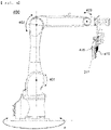
- FIG. 4 is a side view of the robot arm of FIG. 2 .
- the robot arm 400 is configured to be rotatable on the ground in direction a, and includes three rotatable articulation structures 401, 402, and 403.
- the robot arm 400 includes a gripper 410 configured to hold or put down the plurality of battery cells 211.
- the robot arm may perform a process of moving to the plasma treatment unit in a state of holding the plurality of battery cells 211 supplied from the battery cell supply unit while the articulation structures 401, 402, and 403 are unfolded or folded and mounting the battery cells 211 in the battery pack case after plasma treatment.
- the robot arm 400 may be controlled such that plasma treatment is performed in the state in which the plurality of battery cells 211 is disposed above the plasma treatment unit so as to be spaced apart from the plasma treatment unit by a predetermined distance.
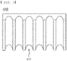
- FIG. 5 is a front view of the gripper.
- FIG. 5 there is shown one of two grippers 410 configured to wrap side surfaces of cylindrical battery cells, wherein the gripper is configured to wrap about 50% of the side surface of each of the cylindrical battery cells.
- the gripper 410 is provided with recesses 411 corresponding respectively to the side surfaces of the cylindrical battery cells such that the cylindrical battery cells can be stably mounted.
- each of the recesses 411 may be anti-slip treated in order to prevent slip of a corresponding one of the cylindrical battery cells.
- the gripper 410 may be configured to perform vacuum suctioning in order to stably fix the cylindrical battery cells while maintaining the aligned state thereof.
- FIG. 6 is a perspective view showing plasma treatment.
- the battery cells 211 are moved to the plasma treatment unit 500 in a state of being mounted at the gripper 410, and are stopped above the plasma device 510.
- the effect of plasma treatment is affected by the distance H between the plasma device 510 and the lower surfaces of the battery cells 211. In order to achieve the same plasma effect for all of the battery cells, the distance H must be maintained uniform.
- the battery cells are transferred using the robot arm, which is capable of performing accurate and minute control, and therefore it is possible to achieve a uniform plasma treatment effect for all of the battery cells.
- the distance H may be 1 mm.
- a battery pack assembly method using the battery pack assembly system may include (a) a step of aligning a plurality of battery cells in the battery cell supply unit, (b) a step of transferring the plurality of battery cells to the plasma treatment unit in a state of holding the plurality of battery cells, (c) a step of treating the plurality of battery cells with plasma, and (d) a step of disposing the plurality of battery cells of step (c) in the battery pack case.
- the distance between the plurality of battery cells and the plasma radiation unit may be maintained uniform.
- the battery pack assembly method may further include a step of treating a first surface of the heat sink, on which the battery cells are disposed, with plasma and a step of applying an adhesive to the first surface treated with plasma, in order to increase adhesive force of an adhesive added between the heat sink and the battery cells.
- a heat sink to be disposed in a battery pack case was prepared, and a first surface of the heat sink was treated with plasma.
- An adhesive was applied to the first surface of the heat sink treated with plasma in order to increase force of adhesion of the adhesive to the heat sink.
- a plurality of battery cells was supplied to the battery cell supply unit in an aligned state using the battery pack assembly system shown in FIG. 2 , and the plurality of battery cells was transferred to the plasma treatment unit using the robot arm. Setting was performed such that the distance between the bottom surfaces of the plurality of battery cells and the plasma device was 1 mm, and the bottom surfaces of the plurality of battery cells were treated with plasma.
- the plurality of battery cells treated with plasma as described above was disposed on the adhesive applied to the first surface of the heat sink.
- the plasma treatment was performed using a 3D+iZET from Applied Plasma Inc.
- a heat sink to be disposed in a battery pack case was prepared, and an adhesive was applied to a first surface of the heat sink.
- a plurality of battery cells was supplied to the battery cell supply unit in an aligned state using the battery pack assembly system shown in FIG. 2 , and the plurality of battery cells was transferred and disposed on the adhesive applied to the first surface of the heat sink using the robot arm.
- a battery pack assembly system is capable of supplying a plurality of battery cells in an aligned state and moving the plurality of battery cells in the state in which the aligned state of the plurality of battery cells is maintained using a robot arm, whereby it is possible to treat the battery cells with plasma in the state in which the battery cells are aligned.
Landscapes
- Engineering & Computer Science (AREA)
- Chemical & Material Sciences (AREA)
- Chemical Kinetics & Catalysis (AREA)
- Electrochemistry (AREA)
- General Chemical & Material Sciences (AREA)
- Manufacturing & Machinery (AREA)
- Mechanical Engineering (AREA)
- Robotics (AREA)
- Physics & Mathematics (AREA)
- Plasma & Fusion (AREA)
- Battery Mounting, Suspending (AREA)
- Secondary Cells (AREA)
- Manipulator (AREA)
- Sealing Battery Cases Or Jackets (AREA)
Abstract
Description
- This application claims the benefit of priority to
Korean Patent Application No. 2020-0113155 filed on September 4, 2020 - The present invention relates to a battery pack assembly system and a battery pack assembly method using the same, and more particularly to a battery pack assembly system that performs plasma treatment in order to increase force of coupling between a battery pack and a heat sink and a battery pack assembly method using the same.
- A secondary battery, which is capable of being repeatedly charged and discharged, has an advantage in that lifespan of a battery cell is long, and is used in a form in which the secondary battery is detachably attached to a device or is built in a device. The kinds of devices using the secondary battery as an energy source have increased.
- In particular, a lithium secondary battery, which is charged and discharged as the result of movement of lithium ions, has been used not only in the field of a small-sized battery cell, which is used for mobile devices or small-sized electronic products, but also in the field of a medium- or large-sized battery pack, which is used as an energy source of an electric vehicle or a power storage system that requires high output and high voltage, since the lithium secondary battery has advantages of high energy density and discharge voltage.
- Based on the shape of a battery case, the lithium secondary battery is classified as a cylindrical secondary battery having an electrode assembly mounted in a cylindrical metal can, a prismatic secondary battery having an electrode assembly mounted in a prismatic metal can, or a pouch-shaped secondary battery having an electrode assembly mounted in a pouch-shaped case made of an aluminum laminate sheet. Thereamong, the cylindrical secondary battery has advantages in that the capacity of the cylindrical secondary battery is relatively large and in that the cylindrical secondary battery is structurally stable.
- In order to manufacture a battery pack including the cylindrical secondary battery as a unit cell, a process of disposing a plurality of cylindrical battery cells in a battery pack case in a compact state, adding a heat dissipation member, such as a heat sink, and hermetically sealing the battery pack case may be performed.
- In order to increase force of adhesion between the heat sink and the plurality of battery cells, an adhesive is applied therebetween. In order to increase adhesive force of the adhesive, surfaces of the heat sink and the battery cells at which the heat sink and the battery cells are adhered to each other may be treated with plasma.
- In connection therewith,
FIG. 1 is a perspective view showing a process of treating the bottom surfaces of conventional cylindrical battery cells with plasma. - Referring to
FIG. 1 , abattery pack case 100 includes anupper case 110 and alower case 120, and a plurality ofbattery cells 200 is disposed in thebattery pack case 100 at predetermined intervals. - A
frame 130 configured to stably fix thebattery cells 200 may be added to the interior of each of theupper case 110 and thelower case 120. - The plurality of
battery cells 200 is disposed such that theupper surfaces 201 thereof face upwards in the state in which theupper case 110 and thelower case 120 are coupled to each other. In order to treat thelower surfaces 202 of the plurality ofbattery cells 200 with plasma, a battery pack is rotated 180 degrees based on an x-axis, and then thelower case 120 is removed such that thelower surfaces 202 of the plurality ofbattery cells 200 are exposed. - In this state, the
lower surfaces 202 of the plurality ofbattery cells 200 are treated with plasma, thelower case 120 is added again, and the battery pack is rotated 180 degrees based on the x-axis so as to be returned to the original state thereof. - In the case in which the lower surfaces of the battery cells are treated with plasma using the above method, the process of mounting the battery cells in the battery pack case and then rotating the battery pack, and the process of removing and mounting the upper case are required, which complicates the overall process.
- Also, in plasma treatment, a plasma treatment effect greatly varies depending on the distance between a target and a plasma device. For this reason, it is necessary to maintain a uniform distance. In the above process, however, it is difficult to maintain a uniform distance between the target and the plasma device.
- Therefore, there is a high necessity for a battery pack assembly system capable of simply performing plasma treatment for a plurality of battery cells, thereby improving productivity and consistently achieving a plasma treatment effect.
- The present invention has been made in view of the above problems, and it is an object of the present invention to provide a battery pack assembly system configured such that bottoms of a plurality of battery cells are treated with plasma in the state in which the plurality of battery cells is aligned so as to be disposed side by side, whereby a plasma treatment effect for the plurality of battery cells is consistently and excellently exhibited, and a battery pack assembly method using the same.
- In order to accomplish the above object, a battery pack assembly system according to the present invention includes a battery cell supply unit configured to supply a plurality of battery cells in an aligned state, a robot arm configured to move the plurality of battery cells, a plasma treatment unit configured to treat the plurality of battery cells with plasma, and an assembly unit in which a battery pack case configured to receive the plurality of battery cells therein is disposed.
- The battery pack assembly system according to the present invention may further include a heat sink disposed in the battery pack case.
- In the battery pack assembly system according to the present invention, an adhesive may be applied to a first surface of the heat sink.
- In the battery pack assembly system according to the present invention, the adhesive may be applied to the first surface of the heat sink on the first surface of the heat sink which is treated with the plasma.
- In the battery pack assembly system according to the present invention, the robot arm may be controlled such that a plasma treatment is performed as the plurality of battery cells are disposed above the plasma treatment unit and spaced apart from the plasma treatment unit by a predetermined distance.
- In the battery pack assembly system according to the present invention, the predetermined distance may be 1 mm.
- In the battery pack assembly system according to the present invention, the plasma treatment unit may be disposed between the battery cell supply unit and the assembly unit.
- In the battery pack assembly system according to the present invention, the robot arm may include a gripper configured to hold or release the plurality of battery cells.
- In the battery pack assembly system according to the present invention, a frame member may be mounted in the battery pack case, and the plurality of battery cells may be disposed at the frame member.
- In addition, the present invention provides a battery pack assembly method using the battery pack assembly system. Specifically, the battery pack assembly method includes (a) aligning the plurality of battery cells in the battery cell supply unit, (b) transferring the plurality of battery cells to the plasma treatment unit by holding the plurality of battery cells, (c) treating the plurality of battery cells with the plasma, and (d) disposing the plurality of battery cells of step (c) in the battery pack case.
- In the battery pack assembly method according to the present invention, the distance between the plurality of battery cells and the plasma radiation unit may be uniform.
- The battery pack assembly method according to the present invention may further include preparing a heat sink to be disposed in the battery pack case, treating a first surface of the heat sink with the plasma, and applying an adhesive to the first surface of the heat sink treated with the plasma.
- As is apparent from the above description, a battery pack assembly system according to the present invention is capable of supplying a plurality of battery cells in an aligned state and moving the plurality of battery cells in the state in which the aligned state of the plurality of battery cells is maintained using a robot arm, whereby it is possible to treat the battery cells with plasma in the state in which the battery cells are aligned.
- Consequently, it is possible to maintain a uniform distance between a plasma treatment unit and the bottoms of the battery cells, whereby it is possible to obtain a uniform plasma treatment effect.
- In addition, it is possible to secure conditions in which the plasma treatment effect can be maximally obtained, whereby it is possible to remarkably increase adhesive force of an adhesive.
-
-
FIG. 1 is a perspective view showing a process of treating the bottom surfaces of conventional cylindrical battery cells with plasma. -
FIG. 2 is a plan view of a battery pack assembly system according to the present invention. -
FIG. 3 is an exploded perspective view of a battery pack according to the present invention. -
FIG. 4 is a side view of a robot arm ofFIG. 2 . -
FIG. 5 is a front view of a gripper. -
FIG. 6 is a perspective view showing plasma treatment. - Now, preferred embodiments of the present invention will be described in detail with reference to the accompanying drawings such that the preferred embodiments of the present invention can be easily implemented by a person having ordinary skill in the art to which the present invention pertains. In describing the principle of operation of the preferred embodiments of the present invention in detail, however, a detailed description of known functions and configurations incorporated herein will be omitted when the same may obscure the subject matter of the present invention.
- In addition, the same reference numbers will be used throughout the drawings to refer to parts that perform similar functions or operations. In the case in which one part is said to be connected to another part throughout the specification, not only may the one part be directly connected to the other part, but also, the one part may be indirectly connected to the other part via a further part. In addition, that a certain element is included does not mean that other elements are excluded, but means that such elements may be further included unless mentioned otherwise.
- In addition, a description to embody elements through limitation or addition may be applied to all inventions, unless particularly restricted, and does not limit a specific invention.
- Also, in the description of the invention and the claims of the present application, singular forms are intended to include plural forms unless mentioned otherwise.
- Also, in the description of the invention and the claims of the present application, "or" includes "and" unless mentioned otherwise. Therefore, "including A or B" means three cases, namely, the case including A, the case including B, and the case including A and B.
- In addition, all numeric ranges include the lowest value, the highest value, and all intermediate values therebetween unless the context clearly indicates otherwise.
- Embodiments of the present invention will be described in detail with reference to the accompanying drawings.
-
FIG. 2 is a plan view of a battery pack assembly system according to the present invention. - Referring to
FIG. 2 , the battery pack assembly system according to the present invention includes a batterycell supply unit 300 configured to supply a plurality of battery cells in an aligned state, arobot arm 400 configured to move the plurality of battery cells, aplasma treatment unit 500 configured to treat the plurality of battery cells with plasma, and anassembly unit 600 in which abattery pack case 610 configured to receive the plurality of battery cells therein is disposed. - The battery pack assembly system according to the present invention, which is used to receive the plurality of battery cells in the battery pack case in order to assemble a battery pack, is characterized in that the battery pack assembly system includes a plasma treatment unit configured to reform lower surfaces of the plurality of battery cells in order to improve adhesiveness of an adhesive used to fix the plurality of battery cells.
- Plasma treatment for the lower surfaces of the plurality of battery cells may be performed in the state in which the
robot arm 400 grips the plurality of battery cells. In order to rapidly perform plasma treatment for the battery cells and the assembly process of the battery pack, theplasma treatment unit 500 may be disposed on a path along which the battery cells supplied from the batterycell supply unit 300 are transferred to theassembly unit 600. - That is, the
plasma treatment unit 500 may be disposed between the batterycell supply unit 300 and theassembly unit 600. - The
assembly unit 600 may include a transfer means configured to transfer thebattery pack case 610 such that thebattery pack case 610 is located adjacent to therobot arm 400. - For example, a conveyor belt or a rail may be used as the transfer means.
- In a concrete example, an adhesive is applied to the inner surface of the lower surface of the battery pack case, in which the battery cells are mounted, and the lower surface of the battery pack case and the battery cells are coupled to each other via the adhesive.
- In order to increase adhesive force of the adhesive, the lower surface of the battery pack case is treated with plasma, and the adhesive is applied to the lower surface of the battery pack case. In addition, the lower surfaces of the battery cells may be treated with plasma. That is, the inner surface of the battery pack case and the lower surfaces of the battery cells that abut each other via the adhesive may be reformed so as to be hydrophilic, whereby adhesiveness of the adhesive may be improved.
- For example, each of the battery cells may be a cylindrical battery cell.
- The battery pack case may include an upper case and a lower case having similar heights. Alternatively, the battery case may include a case body, constituted by a lower surface and four side surface, and a case cover.
- The battery
cell supply unit 300 includes a mountingportion 310, in which the plurality of battery cells is mounted in an aligned state, the bottom of the mounting portion being flat. Consequently, the plurality of battery cells may be aligned such that no difference in height therebetween occurs. - Subsequently, the mounting
portion 310 moves in a direction indicated by an arrow so as to be located adjacent to therobot arm 400 in the state in which the battery cells are mounted therein. - The
robot arm 400 transfers the battery cells aligned in the mountingportion 310 to above theplasma treatment unit 500 in a state of gripping the battery cells without change. At this time, alignment of the battery cells is maintained. Consequently, it is possible to maintain a uniform distance between the bottoms of the battery cells and a plasma device. - A frame member may be mounted in the battery pack case, and the plurality of battery cells may be disposed at the frame member. Consequently, it is possible to stably fix the plurality of battery cells.
- In another concrete example,
FIG. 3 is an exploded perspective view of a battery pack according to the present invention. - Referring to
FIG. 3 , the battery pack includes anupper case 111 and alower case 121, andframe members battery cells 211 are disposed inside theupper case 111 and thelower case 121, respectively. - The battery pack of
FIG. 3 further includes aheat sink 140 in order to secure rapid heat dissipation of thermal energy generated from the plurality ofbattery cells 211. - The
heat sink 140 may be disposed between the inner surface of the lower surface of thelower case 121 and thebattery cells 211. For stable mounting of the battery cells in this structure, it is preferable for an adhesive to be applied between theheat sink 140 and the lower surfaces of thebattery cells 211. The adhesive may be applied to afirst surface 141 of theheat sink 140, at which thebattery cells 211 are disposed. - At this time, in order to increase force of adhesion of the adhesive to the
first surface 141 of the heat sink, the adhesive may be applied to thefirst surface 141 of the heat sink in the state in which the first surface is treated with plasma. -
FIG. 4 is a side view of the robot arm ofFIG. 2 . - Referring to
FIG. 4 , therobot arm 400 is configured to be rotatable on the ground in direction a, and includes threerotatable articulation structures - In addition, the
robot arm 400 includes agripper 410 configured to hold or put down the plurality ofbattery cells 211. - Consequently, the robot arm may perform a process of moving to the plasma treatment unit in a state of holding the plurality of
battery cells 211 supplied from the battery cell supply unit while thearticulation structures battery cells 211 in the battery pack case after plasma treatment. - In addition, the
robot arm 400 may be controlled such that plasma treatment is performed in the state in which the plurality ofbattery cells 211 is disposed above the plasma treatment unit so as to be spaced apart from the plasma treatment unit by a predetermined distance. - Consequently, all of the battery cells transferred by the robot arm are treated with plasma in a state of being uniformly spaced apart from the plasma device, whereby all of the battery cells may be reformed to the same level.
-
FIG. 5 is a front view of the gripper. - Referring to
FIG. 5 , there is shown one of twogrippers 410 configured to wrap side surfaces of cylindrical battery cells, wherein the gripper is configured to wrap about 50% of the side surface of each of the cylindrical battery cells. - The
gripper 410 is provided withrecesses 411 corresponding respectively to the side surfaces of the cylindrical battery cells such that the cylindrical battery cells can be stably mounted. - The outer surface of each of the
recesses 411 may be anti-slip treated in order to prevent slip of a corresponding one of the cylindrical battery cells. - Alternatively, the
gripper 410 may be configured to perform vacuum suctioning in order to stably fix the cylindrical battery cells while maintaining the aligned state thereof. -
FIG. 6 is a perspective view showing plasma treatment. - Referring to
FIG. 6 , thebattery cells 211 are moved to theplasma treatment unit 500 in a state of being mounted at thegripper 410, and are stopped above theplasma device 510. - The effect of plasma treatment is affected by the distance H between the
plasma device 510 and the lower surfaces of thebattery cells 211. In order to achieve the same plasma effect for all of the battery cells, the distance H must be maintained uniform. - In the case in which the battery pack assembly system according to the present invention is used, the battery cells are transferred using the robot arm, which is capable of performing accurate and minute control, and therefore it is possible to achieve a uniform plasma treatment effect for all of the battery cells.
- That is, in the case in which the
robot arm 400 is used, it is possible to maintain the distance H uniform. For example, the distance H may be 1 mm. - A battery pack assembly method using the battery pack assembly system may include (a) a step of aligning a plurality of battery cells in the battery cell supply unit, (b) a step of transferring the plurality of battery cells to the plasma treatment unit in a state of holding the plurality of battery cells, (c) a step of treating the plurality of battery cells with plasma, and (d) a step of disposing the plurality of battery cells of step (c) in the battery pack case.
- At this time, the distance between the plurality of battery cells and the plasma radiation unit may be maintained uniform.
- Also, in the case in which the battery pack includes a heat sink, the battery pack assembly method may further include a step of treating a first surface of the heat sink, on which the battery cells are disposed, with plasma and a step of applying an adhesive to the first surface treated with plasma, in order to increase adhesive force of an adhesive added between the heat sink and the battery cells.
- Hereinafter, the present invention will be described with reference to the following example, which is provided for easier understanding of the present invention, and the category of the present invention is not limited thereto.
- A heat sink to be disposed in a battery pack case was prepared, and a first surface of the heat sink was treated with plasma.
- An adhesive was applied to the first surface of the heat sink treated with plasma in order to increase force of adhesion of the adhesive to the heat sink.
- A plurality of battery cells was supplied to the battery cell supply unit in an aligned state using the battery pack assembly system shown in
FIG. 2 , and the plurality of battery cells was transferred to the plasma treatment unit using the robot arm. Setting was performed such that the distance between the bottom surfaces of the plurality of battery cells and the plasma device was 1 mm, and the bottom surfaces of the plurality of battery cells were treated with plasma. - The plurality of battery cells treated with plasma as described above was disposed on the adhesive applied to the first surface of the heat sink.
- The plasma treatment was performed using a 3D+iZET from Applied Plasma Inc.
- A heat sink to be disposed in a battery pack case was prepared, and an adhesive was applied to a first surface of the heat sink.
- A plurality of battery cells was supplied to the battery cell supply unit in an aligned state using the battery pack assembly system shown in
FIG. 2 , and the plurality of battery cells was transferred and disposed on the adhesive applied to the first surface of the heat sink using the robot arm. - In order to check adhesive force of the battery cells mounted in the battery pack case for each of Example and Comparative Example, tensile force when each individual battery cell was separated from the heat sink was measured. The results are shown in Table 1 below.
-
[Table 1] Tensile force (kgf) Example 186.6 Comparative Example 99.6 - Referring to Table 1 above, it can be seen that the tensile force of Example, in which plasma treatment was performed, was about 87% higher than the tensile force of Comparative Example, in which no plasma treatment was performed.
- In particular, it can be seen that, when plasma treatment is performed in the state in which the distance between the plasma device and the bottom surfaces of the plurality of battery cells is maintained at 1 mm, as in Example, it is possible to obtain a remarkable effect of increasing adhesive force.
- Those skilled in the art to which the present invention pertains will appreciate that various applications and modifications are possible within the category of the present invention based on the above description.
-
- 100: Battery pack case
- 110, 111: Upper cases
- 120, 121: Lower cases
- 130: Frame
- 131, 132: Frame members
- 140: Heat sink
- 141: First surface
- 200, 211: Battery cells
- 201: Upper surface
- 202: Lower surface
- 300: Battery cell supply unit
- 310: Mounting portion
- 400: Robot arm
- 401, 402, 403: Articulation structures
- 410: Gripper
- 411: Recesses
- 500: Plasma treatment unit
- 510: Plasma device
- 600: Assembly unit
- 610: Battery pack case
- H: Distance between plasma device and lower surfaces of battery cells
- As is apparent from the above description, a battery pack assembly system according to the present invention is capable of supplying a plurality of battery cells in an aligned state and moving the plurality of battery cells in the state in which the aligned state of the plurality of battery cells is maintained using a robot arm, whereby it is possible to treat the battery cells with plasma in the state in which the battery cells are aligned.
- Consequently, it is possible to maintain a uniform distance between a plasma treatment unit and the bottoms of the battery cells, whereby it is possible to obtain a uniform plasma treatment effect.
- In addition, it is possible to secure conditions in which the plasma treatment effect can be maximally obtained, whereby it is possible to remarkably increase adhesive force of an adhesive.
Claims (12)
- A battery pack assembly system comprising:a battery cell supply unit configured to supply a plurality of battery cells in an aligned state;a robot arm configured to move the plurality of battery cells;a plasma treatment unit configured to treat the plurality of battery cells with plasma; andan assembly unit in which a battery pack case configured to receive the plurality of battery cells therein is disposed.
- The battery pack assembly system according to claim 1, further comprising a heat sink disposed in the battery pack case.
- The battery pack assembly system according to claim 2, wherein an adhesive is applied to a first surface of the heat sink.
- The battery pack assembly system according to claim 3, wherein the adhesive is applied to the first surface of the heat sink on the first surface of the heat sink which is treated with the plasma.
- The battery pack assembly system according to claim 1, wherein the robot arm is controlled such that a plasma treatment is performed as the plurality of battery cells are disposed above the plasma treatment unit and spaced apart from the plasma treatment unit by a predetermined distance.
- The battery pack assembly system according to claim 5, wherein the predetermined distance is 1 mm.
- The battery pack assembly system according to claim 1, wherein the plasma treatment unit is disposed between the battery cell supply unit and the assembly unit.
- The battery pack assembly system according to claim 1, wherein the robot arm comprises a gripper configured to hold or release the plurality of battery cells.
- The battery pack assembly system according to claim 1, wherein a frame member is mounted in the battery pack case, and
wherein the plurality of battery cells are disposed at the frame member. - A battery pack assembly method using the battery pack assembly system according to any one of claims 1 to 9, the battery pack assembly method comprising:(a) aligning the plurality of battery cells in the battery cell supply unit;(b) transferring the plurality of battery cells to the plasma treatment unit by holding the plurality of battery cells;(c) treating the plurality of battery cells with the plasma; and(d) disposing the plurality of battery cells of step (c) in the battery pack case.
- The battery pack assembly method according to claim 10, wherein a distance between the plurality of battery cells and the plasma radiation unit is uniform in step (c).
- The battery pack assembly method according to claim 10, further comprising:preparing a heat sink to be disposed in the battery pack case;treating a first surface of the heat sink with the plasma; andapplying an adhesive to the first surface of the heat sink treated with the plasma.
Applications Claiming Priority (2)
| Application Number | Priority Date | Filing Date | Title |
|---|---|---|---|
| KR1020200113155A KR102864265B1 (en) | 2020-09-04 | 2020-09-04 | Battery Pack Assembly System and Battery Pack Assembly Method Using the Same |
| PCT/KR2021/011605 WO2022050645A1 (en) | 2020-09-04 | 2021-08-30 | Battery pack assembly system and battery pack assembly method using same |
Publications (3)
| Publication Number | Publication Date |
|---|---|
| EP4123804A1 true EP4123804A1 (en) | 2023-01-25 |
| EP4123804A4 EP4123804A4 (en) | 2024-01-24 |
| EP4123804B1 EP4123804B1 (en) | 2025-11-12 |
Family
ID=80491192
Family Applications (1)
| Application Number | Title | Priority Date | Filing Date |
|---|---|---|---|
| EP21864605.7A Active EP4123804B1 (en) | 2020-09-04 | 2021-08-30 | Battery pack assembly system and battery pack assembly method using the same |
Country Status (7)
| Country | Link |
|---|---|
| US (1) | US12444801B2 (en) |
| EP (1) | EP4123804B1 (en) |
| JP (1) | JP7399403B2 (en) |
| KR (1) | KR102864265B1 (en) |
| CN (1) | CN115380424B (en) |
| ES (1) | ES3055433T3 (en) |
| WO (1) | WO2022050645A1 (en) |
Cited By (1)
| Publication number | Priority date | Publication date | Assignee | Title |
|---|---|---|---|---|
| CN118419340A (en) * | 2024-04-30 | 2024-08-02 | 科捷智能科技股份有限公司 | Cylindrical battery cell taking and placing device and method thereof |
Families Citing this family (1)
| Publication number | Priority date | Publication date | Assignee | Title |
|---|---|---|---|---|
| JP2026512270A (en) * | 2023-08-29 | 2026-04-15 | エルジー エナジー ソリューション リミテッド | Method and apparatus for manufacturing pouch-type batteries |
Family Cites Families (30)
| Publication number | Priority date | Publication date | Assignee | Title |
|---|---|---|---|---|
| JPH08300286A (en) * | 1995-05-09 | 1996-11-19 | Kubota Corp | Robot hand |
| KR0141645B1 (en) | 1995-08-04 | 1998-07-01 | 배순훈 | Battery transfer device |
| KR20080036676A (en) | 2006-10-24 | 2008-04-29 | 삼성전자주식회사 | Manufacturing Method Of Liquid Crystal Display |
| US8519715B2 (en) * | 2010-11-29 | 2013-08-27 | Volkswagen Ag | Method and system for assembling a battery module |
| JP5785131B2 (en) | 2012-05-14 | 2015-09-24 | トヨタ自動車株式会社 | Plasma deposition system |
| KR101643036B1 (en) * | 2013-09-30 | 2016-07-26 | 주식회사 엘지화학 | Apparatus of manufacturing electrode assembly |
| DE102014203765A1 (en) | 2014-02-28 | 2015-09-03 | Bayerische Motoren Werke Aktiengesellschaft | A method of manufacturing an assembly of an energy storage module and a cooling element and assembly |
| KR101670362B1 (en) | 2014-09-04 | 2016-10-31 | 신흥에스이씨주식회사 | CID assembly for a secondary battery and the battery thereof |
| DE102014117866B4 (en) * | 2014-12-04 | 2018-10-11 | Kuka Industries Gmbh | Insulating packaging technology for battery cells and battery cell with appropriate insulation packaging |
| US10403869B2 (en) | 2015-04-13 | 2019-09-03 | Cps Technology Holdings, Llc | Adhesive tape for positioning battery cells in a battery module |
| KR102037841B1 (en) * | 2015-09-24 | 2019-10-30 | 주식회사 엘지화학 | Manufacturing device and manufacturing method for secondary battery |
| KR101977639B1 (en) | 2016-02-16 | 2019-05-14 | 주식회사 엘지화학 | Electrode assembly and manufacturing method of thereof |
| DE102016120345B4 (en) * | 2016-10-25 | 2019-01-31 | Schunk Gmbh & Co. Kg Spann- Und Greiftechnik | battery grippers |
| KR102206154B1 (en) * | 2017-01-12 | 2021-01-22 | 주식회사 엘지화학 | Automated assembling line for top and bottom cap of battery pack and method using thereof |
| WO2018176137A1 (en) * | 2017-03-27 | 2018-10-04 | Planar Motor Incorporated | Robotic devices and methods for fabrication, use and control of same |
| CN207320240U (en) | 2017-09-30 | 2018-05-04 | 苏州安靠电源有限公司 | The two-sided fixture implanter of battery modules |
| JP6770542B2 (en) | 2018-02-22 | 2020-10-14 | 本田技研工業株式会社 | Power supply |
| JP6997949B2 (en) | 2018-03-16 | 2022-02-04 | トヨタ自動車株式会社 | Manufacturing method of laminated battery module |
| CN108767150B (en) | 2018-04-26 | 2021-07-20 | 东莞市天蓝智能装备有限公司 | Power lithium battery module PACK line Cylindrical cell automatic assembly line |
| KR101984889B1 (en) * | 2018-06-29 | 2019-05-31 | 디아인텍 주식회사 | Cell pouch film for battery and method of the same |
| WO2020027299A1 (en) * | 2018-08-03 | 2020-02-06 | 三井化学株式会社 | Cooling plate and battery structure |
| KR102424400B1 (en) | 2018-09-13 | 2022-07-22 | 주식회사 엘지에너지솔루션 | Battery Module Having Heat-Shrinkable Tube |
| CN209364638U (en) | 2018-10-19 | 2019-09-10 | 苏州霄汉工业设备有限公司 | It is a kind of for grabbing the multi-axis robot of battery |
| KR102317265B1 (en) * | 2018-11-02 | 2021-10-22 | 주식회사 엘지에너지솔루션 | Robot Having Robot Arm |
| CN209526168U (en) * | 2018-12-30 | 2019-10-22 | 苏州德星云智能装备有限公司 | A kind of lithium battery mould group battery core surface preparation equipment |
| WO2019101246A2 (en) | 2019-03-21 | 2019-05-31 | Alibaba Group Holding Limited | Data isolation in blockchain networks |
| CN110048151B (en) | 2019-04-23 | 2022-03-15 | 深圳市麦格米特控制技术有限公司 | Battery pack assembling method and device, electronic equipment and storage medium |
| CN110649309B (en) * | 2019-10-18 | 2024-11-12 | 深圳市国威科创新能源科技有限公司 | A power battery module automatic assembly production line |
| CN110931838B (en) * | 2019-12-27 | 2025-04-29 | 昆山华誉自动化科技有限公司 | A battery shell automatic assembly system |
| KR102660448B1 (en) * | 2021-01-19 | 2024-04-23 | 주식회사 엘지에너지솔루션 | Assembly line system of stacked battery module |
-
2020
- 2020-09-04 KR KR1020200113155A patent/KR102864265B1/en active Active
-
2021
- 2021-08-30 EP EP21864605.7A patent/EP4123804B1/en active Active
- 2021-08-30 CN CN202180026548.1A patent/CN115380424B/en active Active
- 2021-08-30 JP JP2022562564A patent/JP7399403B2/en active Active
- 2021-08-30 US US17/921,859 patent/US12444801B2/en active Active
- 2021-08-30 WO PCT/KR2021/011605 patent/WO2022050645A1/en not_active Ceased
- 2021-08-30 ES ES21864605T patent/ES3055433T3/en active Active
Cited By (1)
| Publication number | Priority date | Publication date | Assignee | Title |
|---|---|---|---|---|
| CN118419340A (en) * | 2024-04-30 | 2024-08-02 | 科捷智能科技股份有限公司 | Cylindrical battery cell taking and placing device and method thereof |
Also Published As
| Publication number | Publication date |
|---|---|
| WO2022050645A1 (en) | 2022-03-10 |
| EP4123804A4 (en) | 2024-01-24 |
| JP2023522661A (en) | 2023-05-31 |
| US12444801B2 (en) | 2025-10-14 |
| TW202220275A (en) | 2022-05-16 |
| JP7399403B2 (en) | 2023-12-18 |
| ES3055433T3 (en) | 2026-02-11 |
| KR102864265B1 (en) | 2025-09-26 |
| EP4123804B1 (en) | 2025-11-12 |
| US20230170569A1 (en) | 2023-06-01 |
| KR20220031341A (en) | 2022-03-11 |
| CN115380424A (en) | 2022-11-22 |
| CN115380424B (en) | 2024-12-17 |
Similar Documents
| Publication | Publication Date | Title |
|---|---|---|
| EP4123804B1 (en) | Battery pack assembly system and battery pack assembly method using the same | |
| EP3648223B1 (en) | Unit cell alignment apparatus and electrode assembly manufacturing method using the same | |
| CN105579612B (en) | Substrate carrier with integrated electrostatic chuck | |
| EP3955355A1 (en) | Multi-plate laminating device for lithium battery cell and laminating method thereof | |
| KR102640956B1 (en) | Clamping module, clamping transfer device comprising the same, and secondary battery cell device | |
| US9508541B2 (en) | Apparatus and method for treating substrate | |
| EP2109901B1 (en) | Lithium secondary battery | |
| KR20150053775A (en) | Portable electrostatic chuck carrier for thin substrates | |
| JP7618095B2 (en) | Alignment device and battery module assembly assembly system including the same | |
| KR20150066511A (en) | Workpiece carrier | |
| EP4372872B1 (en) | Cell packaging device | |
| US20210280892A1 (en) | Secondary battery cell supply apparatus for process of folding secondary battery cell | |
| EP4235887A1 (en) | Activation apparatus for secondary battery and activation method therefor | |
| WO2019186411A1 (en) | Electrostatic chuck and substrate processing apparatus | |
| CN118387596A (en) | Automatic feeding and discharging equipment for soft-package cylindrical lithium battery and production line of automatic feeding and discharging equipment | |
| KR102894304B1 (en) | Assembly system and assembly method of battery module assembly | |
| TWI918708B (en) | Battery pack assembly system and battery pack assembly method using the same | |
| KR102236374B1 (en) | Electrostatic Chuck, Apparatus and Method for Carrying Substrates | |
| US20190132910A1 (en) | Tool architecture using variable frequency microwave for residual moisture removal of electrodes | |
| EP4112278A1 (en) | Pouch-type battery case sealing apparatus and pouch-type secondary battery sealing method using same | |
| US12266810B2 (en) | Battery cell assembly, method of manufacturing the same and battery module including battery cell assembly | |
| KR102716527B1 (en) | Manufacturing apparatus and method of cell stack for secondary batteries | |
| US20260131985A1 (en) | Battery cell stacking apparatus and method | |
| KR102788496B1 (en) | Battery cell gripper for precision transfer machine | |
| CN222200576U (en) | Centering adjustment mechanism |
Legal Events
| Date | Code | Title | Description |
|---|---|---|---|
| STAA | Information on the status of an ep patent application or granted ep patent |
Free format text: STATUS: THE INTERNATIONAL PUBLICATION HAS BEEN MADE |
|
| PUAI | Public reference made under article 153(3) epc to a published international application that has entered the european phase |
Free format text: ORIGINAL CODE: 0009012 |
|
| STAA | Information on the status of an ep patent application or granted ep patent |
Free format text: STATUS: REQUEST FOR EXAMINATION WAS MADE |
|
| 17P | Request for examination filed |
Effective date: 20221019 |
|
| AK | Designated contracting states |
Kind code of ref document: A1 Designated state(s): AL AT BE BG CH CY CZ DE DK EE ES FI FR GB GR HR HU IE IS IT LI LT LU LV MC MK MT NL NO PL PT RO RS SE SI SK SM TR |
|
| DAV | Request for validation of the european patent (deleted) | ||
| DAX | Request for extension of the european patent (deleted) | ||
| A4 | Supplementary search report drawn up and despatched |
Effective date: 20240103 |
|
| RIC1 | Information provided on ipc code assigned before grant |
Ipc: H01M 10/04 20060101ALN20231220BHEP Ipc: H01M 10/6554 20140101ALI20231220BHEP Ipc: H01M 10/6556 20140101ALI20231220BHEP Ipc: B25J 15/08 20060101ALI20231220BHEP Ipc: B25J 9/04 20060101ALI20231220BHEP Ipc: B05D 3/14 20060101ALI20231220BHEP Ipc: H01M 10/6551 20140101ALI20231220BHEP Ipc: H01M 50/213 20210101ALI20231220BHEP Ipc: H01M 50/20 20210101AFI20231220BHEP |
|
| GRAP | Despatch of communication of intention to grant a patent |
Free format text: ORIGINAL CODE: EPIDOSNIGR1 |
|
| STAA | Information on the status of an ep patent application or granted ep patent |
Free format text: STATUS: GRANT OF PATENT IS INTENDED |
|
| RIC1 | Information provided on ipc code assigned before grant |
Ipc: H01M 50/20 20210101AFI20250722BHEP Ipc: H01M 50/213 20210101ALI20250722BHEP Ipc: H01M 10/6551 20140101ALI20250722BHEP Ipc: B05D 3/14 20060101ALI20250722BHEP Ipc: B25J 9/04 20060101ALI20250722BHEP Ipc: B25J 15/08 20060101ALI20250722BHEP Ipc: H01M 10/6556 20140101ALI20250722BHEP Ipc: H01M 10/6554 20140101ALI20250722BHEP Ipc: H01M 10/04 20060101ALN20250722BHEP |
|
| INTG | Intention to grant announced |
Effective date: 20250813 |
|
| GRAS | Grant fee paid |
Free format text: ORIGINAL CODE: EPIDOSNIGR3 |
|
| GRAA | (expected) grant |
Free format text: ORIGINAL CODE: 0009210 |
|
| STAA | Information on the status of an ep patent application or granted ep patent |
Free format text: STATUS: THE PATENT HAS BEEN GRANTED |
|
| P01 | Opt-out of the competence of the unified patent court (upc) registered |
Free format text: CASE NUMBER: UPC_APP_6739_4123804/2025 Effective date: 20250911 |
|
| AK | Designated contracting states |
Kind code of ref document: B1 Designated state(s): AL AT BE BG CH CY CZ DE DK EE ES FI FR GB GR HR HU IE IS IT LI LT LU LV MC MK MT NL NO PL PT RO RS SE SI SK SM TR |
|
| REG | Reference to a national code |
Ref country code: CH Ref legal event code: F10 Free format text: ST27 STATUS EVENT CODE: U-0-0-F10-F00 (AS PROVIDED BY THE NATIONAL OFFICE) Effective date: 20251112 Ref country code: GB Ref legal event code: FG4D |
|
| REG | Reference to a national code |
Ref country code: DE Ref legal event code: R096 Ref document number: 602021042405 Country of ref document: DE |
|
| REG | Reference to a national code |
Ref country code: IE Ref legal event code: FG4D |
|
| REG | Reference to a national code |
Ref country code: ES Ref legal event code: FG2A Ref document number: 3055433 Country of ref document: ES Kind code of ref document: T3 Effective date: 20260211 |
|
| REG | Reference to a national code |
Ref country code: NL Ref legal event code: MP Effective date: 20251112 |
|
| REG | Reference to a national code |
Ref country code: LT Ref legal event code: MG9D |
|
| PG25 | Lapsed in a contracting state [announced via postgrant information from national office to epo] |
Ref country code: NO Free format text: LAPSE BECAUSE OF FAILURE TO SUBMIT A TRANSLATION OF THE DESCRIPTION OR TO PAY THE FEE WITHIN THE PRESCRIBED TIME-LIMIT Effective date: 20260212 |
|
| PG25 | Lapsed in a contracting state [announced via postgrant information from national office to epo] |
Ref country code: HR Free format text: LAPSE BECAUSE OF FAILURE TO SUBMIT A TRANSLATION OF THE DESCRIPTION OR TO PAY THE FEE WITHIN THE PRESCRIBED TIME-LIMIT Effective date: 20251112 Ref country code: AT Free format text: LAPSE BECAUSE OF FAILURE TO SUBMIT A TRANSLATION OF THE DESCRIPTION OR TO PAY THE FEE WITHIN THE PRESCRIBED TIME-LIMIT Effective date: 20251112 Ref country code: FI Free format text: LAPSE BECAUSE OF FAILURE TO SUBMIT A TRANSLATION OF THE DESCRIPTION OR TO PAY THE FEE WITHIN THE PRESCRIBED TIME-LIMIT Effective date: 20251112 |
|
| REG | Reference to a national code |
Ref country code: AT Ref legal event code: MK05 Ref document number: 1857581 Country of ref document: AT Kind code of ref document: T Effective date: 20251112 |
|
| PG25 | Lapsed in a contracting state [announced via postgrant information from national office to epo] |
Ref country code: NL Free format text: LAPSE BECAUSE OF FAILURE TO SUBMIT A TRANSLATION OF THE DESCRIPTION OR TO PAY THE FEE WITHIN THE PRESCRIBED TIME-LIMIT Effective date: 20251112 |
|
| PG25 | Lapsed in a contracting state [announced via postgrant information from national office to epo] |
Ref country code: RS Free format text: LAPSE BECAUSE OF FAILURE TO SUBMIT A TRANSLATION OF THE DESCRIPTION OR TO PAY THE FEE WITHIN THE PRESCRIBED TIME-LIMIT Effective date: 20260212 |
|
| PG25 | Lapsed in a contracting state [announced via postgrant information from national office to epo] |
Ref country code: IS Free format text: LAPSE BECAUSE OF FAILURE TO SUBMIT A TRANSLATION OF THE DESCRIPTION OR TO PAY THE FEE WITHIN THE PRESCRIBED TIME-LIMIT Effective date: 20260312 |
|
| PG25 | Lapsed in a contracting state [announced via postgrant information from national office to epo] |
Ref country code: PT Free format text: LAPSE BECAUSE OF FAILURE TO SUBMIT A TRANSLATION OF THE DESCRIPTION OR TO PAY THE FEE WITHIN THE PRESCRIBED TIME-LIMIT Effective date: 20260312 |
|
| PG25 | Lapsed in a contracting state [announced via postgrant information from national office to epo] |
Ref country code: PL Free format text: LAPSE BECAUSE OF FAILURE TO SUBMIT A TRANSLATION OF THE DESCRIPTION OR TO PAY THE FEE WITHIN THE PRESCRIBED TIME-LIMIT Effective date: 20251112 |
|
| PG25 | Lapsed in a contracting state [announced via postgrant information from national office to epo] |
Ref country code: LV Free format text: LAPSE BECAUSE OF FAILURE TO SUBMIT A TRANSLATION OF THE DESCRIPTION OR TO PAY THE FEE WITHIN THE PRESCRIBED TIME-LIMIT Effective date: 20251112 |
|
| PG25 | Lapsed in a contracting state [announced via postgrant information from national office to epo] |
Ref country code: BG Free format text: LAPSE BECAUSE OF FAILURE TO SUBMIT A TRANSLATION OF THE DESCRIPTION OR TO PAY THE FEE WITHIN THE PRESCRIBED TIME-LIMIT Effective date: 20251112 |