EP4123778B1 - Stapelprüfvorrichtung für elektrodenplatte oder einheitszelle - Google Patents
Stapelprüfvorrichtung für elektrodenplatte oder einheitszelle Download PDFInfo
- Publication number
- EP4123778B1 EP4123778B1 EP22758110.5A EP22758110A EP4123778B1 EP 4123778 B1 EP4123778 B1 EP 4123778B1 EP 22758110 A EP22758110 A EP 22758110A EP 4123778 B1 EP4123778 B1 EP 4123778B1
- Authority
- EP
- European Patent Office
- Prior art keywords
- electrode plate
- unit cells
- stacking
- light signal
- inspection apparatus
- Prior art date
- Legal status (The legal status is an assumption and is not a legal conclusion. Google has not performed a legal analysis and makes no representation as to the accuracy of the status listed.)
- Active
Links
Images
Classifications
-
- G—PHYSICS
- G01—MEASURING; TESTING
- G01N—INVESTIGATING OR ANALYSING MATERIALS BY DETERMINING THEIR CHEMICAL OR PHYSICAL PROPERTIES
- G01N21/00—Investigating or analysing materials by the use of optical means, i.e. using sub-millimetre waves, infrared, visible or ultraviolet light
- G01N21/84—Systems specially adapted for particular applications
- G01N21/88—Investigating the presence of flaws or contamination
- G01N21/8806—Specially adapted optical and illumination features
-
- G—PHYSICS
- G01—MEASURING; TESTING
- G01B—MEASURING LENGTH, THICKNESS OR SIMILAR LINEAR DIMENSIONS; MEASURING ANGLES; MEASURING AREAS; MEASURING IRREGULARITIES OF SURFACES OR CONTOURS
- G01B11/00—Measuring arrangements characterised by the use of optical techniques
- G01B11/26—Measuring arrangements characterised by the use of optical techniques for measuring angles or tapers; for testing the alignment of axes
-
- G—PHYSICS
- G01—MEASURING; TESTING
- G01B—MEASURING LENGTH, THICKNESS OR SIMILAR LINEAR DIMENSIONS; MEASURING ANGLES; MEASURING AREAS; MEASURING IRREGULARITIES OF SURFACES OR CONTOURS
- G01B11/00—Measuring arrangements characterised by the use of optical techniques
- G01B11/02—Measuring arrangements characterised by the use of optical techniques for measuring length, width or thickness
- G01B11/06—Measuring arrangements characterised by the use of optical techniques for measuring length, width or thickness for measuring thickness ; e.g. of sheet material
- G01B11/0608—Height gauges
-
- G—PHYSICS
- G01—MEASURING; TESTING
- G01B—MEASURING LENGTH, THICKNESS OR SIMILAR LINEAR DIMENSIONS; MEASURING ANGLES; MEASURING AREAS; MEASURING IRREGULARITIES OF SURFACES OR CONTOURS
- G01B11/00—Measuring arrangements characterised by the use of optical techniques
- G01B11/24—Measuring arrangements characterised by the use of optical techniques for measuring contours or curvatures
-
- G—PHYSICS
- G01—MEASURING; TESTING
- G01N—INVESTIGATING OR ANALYSING MATERIALS BY DETERMINING THEIR CHEMICAL OR PHYSICAL PROPERTIES
- G01N21/00—Investigating or analysing materials by the use of optical means, i.e. using sub-millimetre waves, infrared, visible or ultraviolet light
- G01N21/84—Systems specially adapted for particular applications
- G01N21/88—Investigating the presence of flaws or contamination
- G01N21/95—Investigating the presence of flaws or contamination characterised by the material or shape of the object to be examined
-
- H—ELECTRICITY
- H01—ELECTRIC ELEMENTS
- H01M—PROCESSES OR MEANS, e.g. BATTERIES, FOR THE DIRECT CONVERSION OF CHEMICAL ENERGY INTO ELECTRICAL ENERGY
- H01M10/00—Secondary cells; Manufacture thereof
- H01M10/04—Construction or manufacture in general
-
- H—ELECTRICITY
- H01—ELECTRIC ELEMENTS
- H01M—PROCESSES OR MEANS, e.g. BATTERIES, FOR THE DIRECT CONVERSION OF CHEMICAL ENERGY INTO ELECTRICAL ENERGY
- H01M10/00—Secondary cells; Manufacture thereof
- H01M10/04—Construction or manufacture in general
- H01M10/0404—Machines for assembling batteries
-
- H—ELECTRICITY
- H01—ELECTRIC ELEMENTS
- H01M—PROCESSES OR MEANS, e.g. BATTERIES, FOR THE DIRECT CONVERSION OF CHEMICAL ENERGY INTO ELECTRICAL ENERGY
- H01M10/00—Secondary cells; Manufacture thereof
- H01M10/04—Construction or manufacture in general
- H01M10/0436—Small-sized flat cells or batteries for portable equipment
-
- H—ELECTRICITY
- H01—ELECTRIC ELEMENTS
- H01M—PROCESSES OR MEANS, e.g. BATTERIES, FOR THE DIRECT CONVERSION OF CHEMICAL ENERGY INTO ELECTRICAL ENERGY
- H01M10/00—Secondary cells; Manufacture thereof
- H01M10/04—Construction or manufacture in general
- H01M10/0459—Cells or batteries with folded separator between plate-like electrodes
-
- H—ELECTRICITY
- H01—ELECTRIC ELEMENTS
- H01M—PROCESSES OR MEANS, e.g. BATTERIES, FOR THE DIRECT CONVERSION OF CHEMICAL ENERGY INTO ELECTRICAL ENERGY
- H01M10/00—Secondary cells; Manufacture thereof
- H01M10/05—Accumulators with non-aqueous electrolyte
- H01M10/058—Construction or manufacture
- H01M10/0585—Construction or manufacture of accumulators having only flat construction elements, i.e. flat positive electrodes, flat negative electrodes and flat separators
-
- H—ELECTRICITY
- H01—ELECTRIC ELEMENTS
- H01M—PROCESSES OR MEANS, e.g. BATTERIES, FOR THE DIRECT CONVERSION OF CHEMICAL ENERGY INTO ELECTRICAL ENERGY
- H01M10/00—Secondary cells; Manufacture thereof
- H01M10/04—Construction or manufacture in general
- H01M10/0413—Large-sized flat cells or batteries for motive or stationary systems with plate-like electrodes
-
- Y—GENERAL TAGGING OF NEW TECHNOLOGICAL DEVELOPMENTS; GENERAL TAGGING OF CROSS-SECTIONAL TECHNOLOGIES SPANNING OVER SEVERAL SECTIONS OF THE IPC; TECHNICAL SUBJECTS COVERED BY FORMER USPC CROSS-REFERENCE ART COLLECTIONS [XRACs] AND DIGESTS
- Y02—TECHNOLOGIES OR APPLICATIONS FOR MITIGATION OR ADAPTATION AGAINST CLIMATE CHANGE
- Y02E—REDUCTION OF GREENHOUSE GAS [GHG] EMISSIONS, RELATED TO ENERGY GENERATION, TRANSMISSION OR DISTRIBUTION
- Y02E60/00—Enabling technologies; Technologies with a potential or indirect contribution to GHG emissions mitigation
- Y02E60/10—Energy storage using batteries
-
- Y—GENERAL TAGGING OF NEW TECHNOLOGICAL DEVELOPMENTS; GENERAL TAGGING OF CROSS-SECTIONAL TECHNOLOGIES SPANNING OVER SEVERAL SECTIONS OF THE IPC; TECHNICAL SUBJECTS COVERED BY FORMER USPC CROSS-REFERENCE ART COLLECTIONS [XRACs] AND DIGESTS
- Y02—TECHNOLOGIES OR APPLICATIONS FOR MITIGATION OR ADAPTATION AGAINST CLIMATE CHANGE
- Y02P—CLIMATE CHANGE MITIGATION TECHNOLOGIES IN THE PRODUCTION OR PROCESSING OF GOODS
- Y02P70/00—Climate change mitigation technologies in the production process for final industrial or consumer products
- Y02P70/50—Manufacturing or production processes characterised by the final manufactured product
Definitions
- the present disclosure relates to a stacking inspection apparatus for electrode plates or unit cells.
- a secondary battery is a representative example of an electrochemical device that utilizes such electrochemical energy, and the range of use thereof tends to be gradually expanding.
- the stacking process of the cathode and the anode is performed in various ways.
- the stacking is performed in the form of simply interposing a separator between the cathode and the anode, or is performed by manufacturing mono-cell containing a cathode and a separator or an anode and a separator, bi-cell containing a cathode, an anode and a separator, with electrodes of the same polarity being arranged on the outermost shell on both sides, or full-cell containing a cathode, an anode and a separator, with electrodes of different polarities being arranged in the outermost shell on both sides, folding or stacking them, followed by lamination.
- stacking alignment is also required during folding of unit cells, such as mono-cell, bi-cell, and full-cell, including electrodes and separators, and during stacking between these unit cells in the stacking process.
- the present disclosure has been designed to solve the above-mentioned problems and other technical problems that have yet to be resolved.
- the sensors measure the reciprocating time of the light signal irradiated from the light irradiation units
- the stacking inspection apparatus may further include a measuring unit that measures the thickness according to the position of each of the unit cells from the reciprocating time of each light signal measured from the sensor.
- a stacking inspection apparatus for electrode plates when a first electrode plate and a second electrode plate are stacked so that a separator is interposed between the first electrode plate and the second electrode plate, the apparatus comprising:
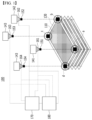
- the stacking inspection apparatus 100 is a stacking inspection apparatus 100 that inspects the alignment state of electrode plates 110 and 120 when the first electrode plate 110 and the second electrode plate 120 are stacked so that a separator 130 is interposed between the first electrode plate 110 and the second electrode plate 120 .
- the stacking inspection apparatus 100 includes camera units 141, 142, 143 and 144 that generate an aligned image by photographing four corner points a, b, c and d of the outer periphery of the first electrode plate110 or the second electrode plate 120 at an upper part in a stacking direction of the first electrode plate 110 and the second electrode plate 120; and light irradiation units 151, 152, 153 and 154 that irradiate light signals to four corner points of the first electrode plate 110 and the second electrode plate 120 as inspection objects at the upper part of the first electrode plate 110 or the second electrode plate 120, when the first electrode plate 110 and the second electrode plate 120 are stacked, wherein the camera units 141, 142, 143 and 144 include sensors 161, 162, 163 and 164 that recognize the light signal irradiated from the light irradiation units 151, 152, 153 and 154 and determine whether alignment of the first electrode plate 110 and the second electrode plate 120 is defective.
- the sensors 161, 162, 163 and 164 may inform an operator of this visually or audibly.
- the alignment correction can be automated by the control unit 180, the alignment correction can be performed in real time.
- the present disclosure since it is possible to determine in real time whether or not the electrode plates 110 and 120 are aligned each time they are stacked, it is possible to produce a product that is more aligned than before. Further, since the time required for the cathode-anode interval inspection performed at the time of product production in the past can be shortened, the product quality and yield can be improved.
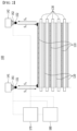
- the sensors 161, 162, 163 and 164 can further measure the reciprocating time of the light signal irradiated from the light irradiation units 151, 152, 153, and 154. That is, the sensors 161, 162, 163, and 164 can measure the time when the light signal is recognized again from the time when the light signal is irradiated in connection with the light irradiation units 151, 152, 153 and 154, and the time (S1+ S2, S3+S3) when the light signal starts from the light irradiation units 151, 152, 153 and 154, reaches the electrode plate 110, and is recognized by the sensors 161, 162, 163, and 164 again, as shown in Fig. 2 .
- a difference may occur between the four corner points a, b, c and d until the light signal is recognized again, from which the thickness at each position of the electrode plates can be estimated.
- the measurement unit 170 stores information about the distance between the light irradiation units 151, 152, 153 and 154 for each stacking and the electrode plate located at the outermost shell at each stacking, and calculates the interval after the new electrode plate is stacked from the reciprocating time of the light signal, whereby the thickness of the newly stacked electrode plate can be measured from [the distance between the outermost electrode plate and the light irradiation units 151, 152, 153 and 154 before stacking - the distance between the outermost electrode plate and the light irradiation units 151, 152, 153 and 154 after stacking new electrode plates].
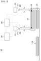
- Figs. 3 and 4 schematically show side views of the stacking inspection apparatuses 200 and 300 for such unit cells.
- the unit cells 210, 220 and 230 are stacked in the form of winding in one direction such that a separation film 240 is interposed between the one or more unit cells 210, 220 and 230, thereby manufacturing an electrode assembly.
- the stacking inspection apparatus may further include a measuring unit 280 that measures the thickness according to the position of each of the unit cells 210, 220 and 230 from the reciprocating time of each light signal measured from the sensors 271 and 272.
- the stacking inspection apparatus may further include a control unit 290 that corrects the alignment value according to information received from the sensors 271 and 272 and instructs the correction of the stacking position of the unit cells 210, 220 and 230 when the sensors 271 and 272 have determined to be alignment defects, and determines to be defective when the reciprocating time difference of each light signal measured from the sensors 271 and 272 is equal to or greater than a certain value, or when the thickness deviation depending on the position of each of the unit cells 210, 220 and 230 measured from the measurement unit 280 is equal to or greater than a certain value.
- a control unit 290 that corrects the alignment value according to information received from the sensors 271 and 272 and instructs the correction of the stacking position of the unit cells 210, 220 and 230 when the sensors 271 and 272 have determined to be alignment defects, and determines to be defective when the reciprocating time difference of each light signal measured from the sensors 271 and 272 is equal to or greater than a certain value, or when the thickness deviation depending on the position
- the thickness is different from that of the stacking inspection apparatus 100 of Fig. 1 in that the thickness of the unit cells 210, 220 and 230 is measured.
- Fig. 3 shows only a format in which the unit cells 210, 220 and 230 are wound in one direction, but it goes without saying that the stacking inspection apparatus 200 according to the present disclosure can be applied even when the separation film is stacked in a form in which unit cells are folded in a zigzag manner.
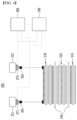
- an electrode assembly is manufactured in such a manner that a separator 340 is stacked in a form of interposing and stacking between one or more unit cells 310, 320 and 330.
- the sensors 371 and 372 can measure the reciprocating time of the light signal irradiated from the light irradiation units 361 and 362, and the stacking inspection apparatus 300 may further include a measuring unit 380 that measures the thickness according to the position of each of the unit cells 310, 320 and 330 from the reciprocating time of each light signal measured from the sensors 371 and 372.
- the stacking inspection apparatus may further include a control unit 390 that corrects the alignment value according to information received from the sensors 371 and 372 and instructs the correction of the stacking position of the unit cells 310, 320 and 330 when the sensors 371 and 372 have determined to be alignment defects, and determines to be defective when the reciprocating time difference of each light signal measured from the sensors 271 and 272 is equal to or greater than a certain value, or when the thickness deviation depending on the position of each of the unit cells 310, 320 and 330 measured from the measurement unit 380 is equal to or greater than a certain value.
- a control unit 390 that corrects the alignment value according to information received from the sensors 371 and 372 and instructs the correction of the stacking position of the unit cells 310, 320 and 330 when the sensors 371 and 372 have determined to be alignment defects, and determines to be defective when the reciprocating time difference of each light signal measured from the sensors 271 and 272 is equal to or greater than a certain value, or when the thickness deviation depending on the position
- the stacking inspection apparatus can inspect the stacking alignment defects of the electrode plates or the unit cells in real time by adding a light irradiation unit for irradiating a light signal to the apparatus used in the existing process, and adding a sensor to a camera.
- the time required for alignment inspection or interval inspection between cathode and anode during production can be reduced, and alignment defects can also be drastically reduced, so that the product performance can be enhanced, thus improving the product quality and improving the yield.
- the thickness difference at each position of the electrode plates or unit cells can be measured through the light irradiation unit used in the stacking inspection apparatus, it is possible to detect a loading defect, etc. with a large thickness deviation at each position. Therefore, it is possible to minimize errors that appear when an operator directly measures it, and it is possible to detect and remove electrode plates or unit cells having loading defects or thickness defects in advance, thus further improving the product quality.
Landscapes
- Chemical & Material Sciences (AREA)
- Engineering & Computer Science (AREA)
- Manufacturing & Machinery (AREA)
- Chemical Kinetics & Catalysis (AREA)
- Electrochemistry (AREA)
- General Chemical & Material Sciences (AREA)
- Physics & Mathematics (AREA)
- General Physics & Mathematics (AREA)
- Health & Medical Sciences (AREA)
- Life Sciences & Earth Sciences (AREA)
- Analytical Chemistry (AREA)
- Biochemistry (AREA)
- General Health & Medical Sciences (AREA)
- Immunology (AREA)
- Pathology (AREA)
- Secondary Cells (AREA)
Claims (11)
- Stapelinspektionsvorrichtung (100; 200; 300) für Elektrodenplatten, wenn eine erste Elektrodenplatte (110) und eine zweite Elektrodenplatte (120) gestapelt sind, so dass ein Separator (130; 340) zwischen der ersten Elektrodenplatte (110) und der zweiten Elektrodenplatte (120) angeordnet ist, wobei die Vorrichtung aufweist:Kameraeinheiten (141; 142; 143; 144; 251; 252; 351; 352), die ein ausgerichtetes Bild durch Fotografieren von vier Eckpunkten des Außenumfangs der ersten Elektrodenplatte (110) oder der zweiten Elektrodenplatte (120) an einem oberen Teil in einer Stapelrichtung der ersten Elektrodenplatte (110) und der zweiten Elektrodenplatte (120) erzeugen; undLichtbestrahlungseinheiten (151; 152; 153; 154; 261; 262; 361; 362), die ein Lichtsignal auf vier Eckpunkte der ersten Elektrodenplatte (110) und der zweiten Elektrodenplatte (120) als Inspektionsobjekte am oberen Teil der ersten Elektrodenplatte (110) oder der zweiten Elektrodenplatte (120) strahlen, wenn die erste Elektrodenplatte (110) und die zweite Elektrodenplatte (120) gestapelt sind,wobei jede Kameraeinheit (141; 142; 143; 144; 251; 252; 351; 352) der Kameraeinheiten (141; 142; 143; 144; 251; 252; 351; 352) einen Sensor (161; 162; 163; 164; 271; 272; 371; 372) aufweist,wobei die Sensoren (161; 162; 163; 164; 271; 272; 371; 372) das von den Lichtbestrahlungseinheiten (151; 152; 153; 154; 261; 262; 361; 362) abgestrahlte Lichtsignal erkennen, eine Hin- und Herbewegungszeit des von den Lichtbestrahlungseinheiten (151; 152; 153; 154; 261; 262; 361; 362) abgestrahlten Lichtsignals messen und bestimmen, ob die Ausrichtung der ersten Elektrodenplatte (110) und der zweiten Elektrodenplatte (120) fehlerhaft ist oder nicht.
- Stapelinspektionsvorrichtung (100; 200; 300) nach Anspruch 1, wobei:
die Lichtbestrahlungseinheiten (151; 152; 153; 154; 261; 262; 361; 362) das Lichtsignal so abstrahlen, dass das Lichtsignal durch die vier Eckpunkte hindurchgeht, wenn die erste Elektrodenplatte (110) oder die zweite Elektrodenplatte (120) teilweise sogar in einer von links/rechts/oben/unten Richtungen an der Position, wo die Platten gestapelt werden sollten, abgelenkt wird. - Stapelinspektionsvorrichtung (100; 200; 300) nach Anspruch 1 oder 2, wobei:
die Sensoren (161; 162; 163; 164; 271; 272; 371; 372) die Ausrichtung als fehlerhaft bestimmen, wenn mindestens ein Lichtsignal durch die vier Eckpunkte hindurchgeht. - Stapelinspektionsvorrichtung (100; 200; 300) nach Anspruch 1, ferner aufweisend:
eine Messeinheit (170; 280; 380), die die Dicke gemäß der Position jeder der ersten Elektrodenplatte (110) oder der zweiten Elektrodenplatte (120) aus der Hin- und Herbewegungszeit jedes von den Sensoren (161; 162; 163; 164; 271; 272; 371; 372) gemessenen Lichtsignals misst. - Stapelinspektionsvorrichtung (100; 200; 300) nach Anspruch 4, wobei:
die Stapelinspektionsvorrichtung (100; 200; 300) ferner eine Steuereinheit (180; 290; 390) aufweist, die den Ausrichtungswert gemäß von den Sensoren (161; 162; 163; 164; 271; 272; 371; 372) empfangenen Informationen korrigiert und die Korrektur der Stapelposition der ersten Elektrodenplatte (110) oder der zweiten Elektrodenplatte (120) anweist, wenn die Sensoren (161; 162; 163; 164; 271; 272; 371; 372) die Ausrichtung als fehlerhaft bestimmen, und die Ausrichtung als fehlerhaft bestimmt, wenn die Hin- und Herbewegungszeitdifferenz jedes von den Sensoren (161; 162; 163; 164; 271; 272; 371; 372) gemessenen Lichtsignals gleich oder größer als ein bestimmter Wert ist, oder wenn die von der Messeinheit gemessene Dickenabweichung in Abhängigkeit von der Position jeder der ersten Elektrodenplatte (110) oder der zweiten Elektrodenplatte (120) gleich oder größer als ein bestimmter Wert ist. - Stapelinspektionsvorrichtung (100; 200; 300) für Einheitszellen (210; 220; 230; 310; 320; 330), wenn die Einheitszellen (210; 220; 230; 310; 320; 330) gestapelt sind, so dass ein Trennfilm (240) oder ein Separator (130; 340) zwischen einer oder mehreren Einheitszellen (210; 220; 230; 310; 320; 330) angeordnet ist, wobei die Vorrichtung aufweist:Kameraeinheiten (141; 142; 143; 144; 251; 252; 351; 352), die ein ausgerichtetes Bild durch Fotografieren von vier Eckpunkten des Außenumfangs der Einheitszellen (210; 220; 230; 310; 320; 330) an einem oberen Teil in einer Stapelrichtung der Einheitszellen (210; 220; 230; 310; 320; 330) erzeugen; undLichtbestrahlungseinheiten, die ein Lichtsignal auf vier Eckpunkte der Einheitszellen (210; 220; 230; 310; 320; 330) als Inspektionsobjekte am oberen Teil der Einheitszellen (210; 220; 230; 310; 320; 330) strahlen, wenn die Einheitszellen (210; 220; 230; 310; 320; 330) gestapelt sind,wobei jede Kameraeinheit (141; 142; 143; 144; 251; 252; 351; 352) der Kameraeinheiten (141; 142; 143; 144; 251; 252; 351; 352) einen Sensor aufweist,wobei die Sensoren (161; 162; 163; 164; 271; 272; 371; 372) das von den Lichtbestrahlungseinheiten (151; 152; 153; 154; 261; 262; 361; 362) abgestrahlte Lichtsignal erkennen, eine Hin- und Herbewegungszeit des von den Lichtbestrahlungseinheiten (151; 152; 153; 154; 261; 262; 361; 362) abgestrahlten Lichtsignals messen und bestimmen, ob die Ausrichtung der Einheitszellen (210; 220; 230; 310; 320; 330) fehlerhaft ist oder nicht.
- Stapelinspektionsvorrichtung (100; 200; 300) nach Anspruch 6, wobei:
die Lichtbestrahlungseinheiten (151; 152; 153; 154; 261; 262; 361; 362) das Lichtsignal so abstrahlen, dass das Lichtsignal durch die vier Eckpunkte hindurchgeht, wenn die Einheitszellen (210; 220; 230; 310; 320; 330) teilweise sogar in einer von links/rechts/oben/unten Richtungen an der Position, wo die Einheitszellen (210; 220; 230; 310; 320; 330) gestapelt werden sollten, abgelenkt werden. - Stapelinspektionsvorrichtung (100; 200; 300) nach Anspruch 6 oder 7, wobei:
die Sensoren (161; 162; 163; 164; 271; 272; 371; 372) die Ausrichtung als fehlerhaft bestimmen, wenn mindestens ein Lichtsignal durch die vier Eckpunkte hindurchgeht. - Stapelinspektionsvorrichtung (100; 200; 300) nach Anspruch 6, ferner aufweisend:
eine Messeinheit (170; 280; 380), die die Dicke gemäß der Position jeder der Einheitszellen (210; 220; 230; 310; 320; 330) aus der Hin- und Herbewegungszeit jedes von den Sensoren (161; 162; 163; 164; 271; 272; 371; 372) gemessenen Lichtsignals misst. - Stapelinspektionsvorrichtung (100; 200; 300) nach Anspruch 9, wobei:
die Stapelinspektionsvorrichtung (100; 200; 300) ferner eine Steuereinheit (180; 290; 390) aufweist, die den Ausrichtungswert gemäß von den Sensoren (161; 162; 163; 164; 271; 272; 371; 372) empfangenen Informationen korrigiert und die Korrektur der Stapelposition der Einheitszellen (210; 220; 230; 310; 320; 330) anweist, wenn die Sensoren (161; 162; 163; 164; 271; 272; 371; 372) die Ausrichtung als fehlerhaft bestimmen, und die Ausrichtung als fehlerhaft bestimmt, wenn die Hin- und Herbewegungszeitdifferenz jedes von den Sensoren (161; 162; 163; 164; 271; 272; 371; 372) gemessenen Lichtsignals gleich oder größer als ein bestimmter Wert ist, oder wenn die von der Messeinheit gemessene Dickenabweichung in Abhängigkeit von der Position jeder der Einheitszellen (210; 220; 230; 310; 320; 330) gleich oder größer als ein bestimmter Wert ist. - Stapelinspektionsvorrichtung (100; 200; 300) nach Anspruch 6, wobei:
die Einheitszellen (210; 220; 230; 310; 320; 330) derart gestapelt sind, dass der Trennfilm (240) die Einheitszellen (210; 220; 230; 310; 320; 330) in einer Richtung wickelt, oder derart gestapelt sind, dass der Trennfilm (240) die Einheitszellen (210; 220; 230; 310; 320; 330) zickzackförmig faltet, oder derart gestapelt sind, dass der Separator (130; 340) zwischen den Einheitszellen (210; 220; 230; 310; 320; 330) angeordnet und laminiert ist.
Applications Claiming Priority (2)
| Application Number | Priority Date | Filing Date | Title |
|---|---|---|---|
| KR1020210074998A KR102821620B1 (ko) | 2021-06-09 | 2021-06-09 | 전극판 또는 단위셀 적층 검사 장치 |
| PCT/KR2022/003218 WO2022260245A1 (ko) | 2021-06-09 | 2022-03-07 | 전극판 또는 단위셀 적층 검사 장치 |
Publications (3)
| Publication Number | Publication Date |
|---|---|
| EP4123778A1 EP4123778A1 (de) | 2023-01-25 |
| EP4123778A4 EP4123778A4 (de) | 2023-09-06 |
| EP4123778B1 true EP4123778B1 (de) | 2024-07-03 |
Family
ID=84047773
Family Applications (1)
| Application Number | Title | Priority Date | Filing Date |
|---|---|---|---|
| EP22758110.5A Active EP4123778B1 (de) | 2021-06-09 | 2022-03-07 | Stapelprüfvorrichtung für elektrodenplatte oder einheitszelle |
Country Status (7)
| Country | Link |
|---|---|
| US (1) | US20240183789A1 (de) |
| EP (1) | EP4123778B1 (de) |
| KR (1) | KR102821620B1 (de) |
| CN (1) | CN115943510A (de) |
| ES (1) | ES2989965T3 (de) |
| HU (1) | HUE067986T2 (de) |
| WO (1) | WO2022260245A1 (de) |
Families Citing this family (6)
| Publication number | Priority date | Publication date | Assignee | Title |
|---|---|---|---|---|
| EP4369292B1 (de) * | 2022-04-08 | 2025-12-17 | Contemporary Amperex Technology (Hong Kong) Limited | Versatzdetektionsverfahren und -vorrichtung, fördervorrichtung und speichermedium |
| CN117053730B (zh) * | 2023-10-11 | 2024-02-02 | 杭州睿影科技有限公司 | 一种叠片式电池的检测方法、装置、图像处理设备及介质 |
| DE102023128068A1 (de) * | 2023-10-13 | 2025-04-17 | Körber Technologies Gmbh | Messvorrichtung und Messverfahren zur Bestimmung mindestens einer Eigenschaft eines flächigen Elements der Batteriezellen produzierenden Industrie |
| KR20250114764A (ko) * | 2024-01-22 | 2025-07-29 | 주식회사 엘지에너지솔루션 | 이차전지 스태킹 장치 및 이의 제어방법 |
| CN118004618B (zh) * | 2024-02-27 | 2026-01-06 | 布勒(无锡)商业有限公司 | 复合信息化集装箱区多功能辅助系统和方法 |
| WO2026005562A1 (ko) * | 2024-06-27 | 2026-01-02 | 주식회사 엘지에너지솔루션 | 단위셀 검사 장치 및 이를 이용한 단위셀 검사 방법 |
Family Cites Families (9)
| Publication number | Priority date | Publication date | Assignee | Title |
|---|---|---|---|---|
| KR102042467B1 (ko) * | 2016-03-04 | 2019-11-08 | 주식회사 엘지화학 | 레이저 센서를 포함하는 전지셀 두께 측정장치 및 이를 사용하여 전지셀의 두께를 측정하는 방법 |
| US10293547B2 (en) * | 2016-06-07 | 2019-05-21 | Xerox Corporation | Electrostatic 3-D printer using layer and mechanical planer |
| KR102255705B1 (ko) * | 2016-07-26 | 2021-05-26 | 엘지전자 주식회사 | 셀적층 및 열압착 장치, 및 셀적층 및 열압착 방법 |
| KR101992467B1 (ko) * | 2017-11-07 | 2019-06-24 | (주)피토 | 극판 검사 기능을 포함하는 2차전지 제조장치의 극판이송장치 |
| WO2019160305A1 (ko) * | 2018-02-13 | 2019-08-22 | 주식회사 이노메트리 | 이차전지용 고속 스택 제조 장치 |
| KR102629119B1 (ko) * | 2018-05-02 | 2024-01-26 | 에스케이온 주식회사 | 전극판 정렬 상태 검사 시스템 및 방법 |
| KR102177841B1 (ko) * | 2018-11-22 | 2020-11-11 | 주식회사 강한이노시스 | 조명을 이용한 2차전지 전극 적층 감시 장치 |
| KR102107226B1 (ko) | 2018-12-20 | 2020-05-07 | 김태완 | 적층 전지 정렬 검사 장치 |
| KR102904508B1 (ko) * | 2019-01-11 | 2025-12-30 | 한국전자통신연구원 | 이차전지용 엑스선 검사 장치 |
-
2021
- 2021-06-09 KR KR1020210074998A patent/KR102821620B1/ko active Active
-
2022
- 2022-03-07 ES ES22758110T patent/ES2989965T3/es active Active
- 2022-03-07 HU HUE22758110A patent/HUE067986T2/hu unknown
- 2022-03-07 CN CN202280003003.3A patent/CN115943510A/zh active Pending
- 2022-03-07 US US17/915,403 patent/US20240183789A1/en active Pending
- 2022-03-07 WO PCT/KR2022/003218 patent/WO2022260245A1/ko not_active Ceased
- 2022-03-07 EP EP22758110.5A patent/EP4123778B1/de active Active
Also Published As
| Publication number | Publication date |
|---|---|
| US20240183789A1 (en) | 2024-06-06 |
| EP4123778A4 (de) | 2023-09-06 |
| ES2989965T3 (es) | 2024-11-28 |
| KR102821620B1 (ko) | 2025-06-16 |
| HUE067986T2 (hu) | 2024-12-28 |
| CN115943510A (zh) | 2023-04-07 |
| KR20220166098A (ko) | 2022-12-16 |
| WO2022260245A1 (ko) | 2022-12-15 |
| EP4123778A1 (de) | 2023-01-25 |
Similar Documents
| Publication | Publication Date | Title |
|---|---|---|
| EP4123778B1 (de) | Stapelprüfvorrichtung für elektrodenplatte oder einheitszelle | |
| EP3565052B1 (de) | Elektrodenplattenausgerichtetes zustandsinspektionssystem und verfahren | |
| US11372052B2 (en) | Jig pressing-type pressing short-circuiting inspection method | |
| JP5583480B2 (ja) | リチウムイオン二次電池の検査方法 | |
| KR20220111363A (ko) | 원통형 전지셀의 코어 변형 정도 평가 방법 및 장치 | |
| KR20120096621A (ko) | 초음파 용접의 강도 검사 방법 및 장치 | |
| KR20220087027A (ko) | 전지셀 검사 시스템 및 전지셀 검사 방법 | |
| KR20200059483A (ko) | 저전압 불량 전지셀 검출을 위한 가압단락 검사장치 | |
| KR102624807B1 (ko) | 전극 조립체 및 이의 검사 방법 | |
| KR20130124098A (ko) | 바이셀의 제조방법 | |
| KR20200059559A (ko) | 이차전지셀 디가스시스템 | |
| KR20160068244A (ko) | 전극조립체의 불량 유무 선별용 가압장치 및 불량 유무 선별방법 | |
| EP4113696B1 (de) | System zur erkennung eines defekts einer elektrodenlasche und verfahren zur erkennung eines defekts einer elektrodenlasche damit | |
| KR20200053784A (ko) | 전지셀의 전극 탭 접힘 불량 판별 시스템 및 그 방법 | |
| US11841328B2 (en) | Method and device for testing electrode sheet | |
| KR20200059560A (ko) | 이차전지셀 롤링모듈 | |
| KR20220118250A (ko) | 모노셀 형태의 분리막 손상 검출 장치 및 방법 | |
| KR20220138739A (ko) | 상대 비교를 통한 이상 전지 검출 방법 | |
| EP4372855A1 (de) | Herstellungsverfahren für eine elektrodenanordnung | |
| JP7011782B2 (ja) | 二次電池の検査方法 | |
| KR102479303B1 (ko) | 지그 프레스 장치 | |
| EP4249904B1 (de) | Vorrichtung und verfahren zur erkennung interner defekte einer batteriezelle unter verwendung von tdr | |
| KR20240173491A (ko) | 불량 검사장치 및 불량 검사방법 | |
| KR20220020493A (ko) | 다수의 가압 롤러를 포함하는 분리막 손상 검출 장치 및 이를 사용한 분리막 손상 검출 방법 |
Legal Events
| Date | Code | Title | Description |
|---|---|---|---|
| STAA | Information on the status of an ep patent application or granted ep patent |
Free format text: STATUS: UNKNOWN |
|
| STAA | Information on the status of an ep patent application or granted ep patent |
Free format text: STATUS: THE INTERNATIONAL PUBLICATION HAS BEEN MADE |
|
| PUAI | Public reference made under article 153(3) epc to a published international application that has entered the european phase |
Free format text: ORIGINAL CODE: 0009012 |
|
| STAA | Information on the status of an ep patent application or granted ep patent |
Free format text: STATUS: REQUEST FOR EXAMINATION WAS MADE |
|
| 17P | Request for examination filed |
Effective date: 20220901 |
|
| AK | Designated contracting states |
Kind code of ref document: A1 Designated state(s): AL AT BE BG CH CY CZ DE DK EE ES FI FR GB GR HR HU IE IS IT LI LT LU LV MC MK MT NL NO PL PT RO RS SE SI SK SM TR |
|
| REG | Reference to a national code |
Ref country code: DE Ref legal event code: R079 Free format text: PREVIOUS MAIN CLASS: H01M0010040000 Ipc: G01B0011260000 Ref country code: DE Ref legal event code: R079 Ref document number: 602022004367 Country of ref document: DE Free format text: PREVIOUS MAIN CLASS: H01M0010040000 Ipc: G01B0011260000 |
|
| A4 | Supplementary search report drawn up and despatched |
Effective date: 20230804 |
|
| RIC1 | Information provided on ipc code assigned before grant |
Ipc: G01N 21/95 20060101ALI20230731BHEP Ipc: G01B 11/06 20060101ALI20230731BHEP Ipc: H01M 10/04 20060101ALI20230731BHEP Ipc: G01B 11/26 20060101AFI20230731BHEP |
|
| GRAP | Despatch of communication of intention to grant a patent |
Free format text: ORIGINAL CODE: EPIDOSNIGR1 |
|
| STAA | Information on the status of an ep patent application or granted ep patent |
Free format text: STATUS: GRANT OF PATENT IS INTENDED |
|
| DAV | Request for validation of the european patent (deleted) | ||
| DAX | Request for extension of the european patent (deleted) | ||
| INTG | Intention to grant announced |
Effective date: 20240409 |
|
| RIC1 | Information provided on ipc code assigned before grant |
Ipc: H01M 10/0585 20100101ALI20240322BHEP Ipc: G01N 21/95 20060101ALI20240322BHEP Ipc: H01M 10/04 20060101ALI20240322BHEP Ipc: G01B 11/06 20060101ALI20240322BHEP Ipc: G01B 11/26 20060101AFI20240322BHEP |
|
| GRAS | Grant fee paid |
Free format text: ORIGINAL CODE: EPIDOSNIGR3 |
|
| GRAA | (expected) grant |
Free format text: ORIGINAL CODE: 0009210 |
|
| STAA | Information on the status of an ep patent application or granted ep patent |
Free format text: STATUS: THE PATENT HAS BEEN GRANTED |
|
| AK | Designated contracting states |
Kind code of ref document: B1 Designated state(s): AL AT BE BG CH CY CZ DE DK EE ES FI FR GB GR HR HU IE IS IT LI LT LU LV MC MK MT NL NO PL PT RO RS SE SI SK SM TR |
|
| REG | Reference to a national code |
Ref country code: CH Ref legal event code: EP |
|
| REG | Reference to a national code |
Ref country code: DE Ref legal event code: R096 Ref document number: 602022004367 Country of ref document: DE |
|
| P01 | Opt-out of the competence of the unified patent court (upc) registered |
Free format text: CASE NUMBER: APP_41107/2024 Effective date: 20240711 |
|
| REG | Reference to a national code |
Ref country code: LT Ref legal event code: MG9D |
|
| REG | Reference to a national code |
Ref country code: NL Ref legal event code: MP Effective date: 20240703 |
|
| REG | Reference to a national code |
Ref country code: ES Ref legal event code: FG2A Ref document number: 2989965 Country of ref document: ES Kind code of ref document: T3 Effective date: 20241128 |
|
| PG25 | Lapsed in a contracting state [announced via postgrant information from national office to epo] |
Ref country code: PT Free format text: LAPSE BECAUSE OF FAILURE TO SUBMIT A TRANSLATION OF THE DESCRIPTION OR TO PAY THE FEE WITHIN THE PRESCRIBED TIME-LIMIT Effective date: 20241104 |
|
| REG | Reference to a national code |
Ref country code: AT Ref legal event code: MK05 Ref document number: 1700223 Country of ref document: AT Kind code of ref document: T Effective date: 20240703 |
|
| PG25 | Lapsed in a contracting state [announced via postgrant information from national office to epo] |
Ref country code: NL Free format text: LAPSE BECAUSE OF FAILURE TO SUBMIT A TRANSLATION OF THE DESCRIPTION OR TO PAY THE FEE WITHIN THE PRESCRIBED TIME-LIMIT Effective date: 20240703 |
|
| REG | Reference to a national code |
Ref country code: HU Ref legal event code: AG4A Ref document number: E067986 Country of ref document: HU |
|
| PG25 | Lapsed in a contracting state [announced via postgrant information from national office to epo] |
Ref country code: PT Free format text: LAPSE BECAUSE OF FAILURE TO SUBMIT A TRANSLATION OF THE DESCRIPTION OR TO PAY THE FEE WITHIN THE PRESCRIBED TIME-LIMIT Effective date: 20241104 Ref country code: NL Free format text: LAPSE BECAUSE OF FAILURE TO SUBMIT A TRANSLATION OF THE DESCRIPTION OR TO PAY THE FEE WITHIN THE PRESCRIBED TIME-LIMIT Effective date: 20240703 |
|
| PG25 | Lapsed in a contracting state [announced via postgrant information from national office to epo] |
Ref country code: NO Free format text: LAPSE BECAUSE OF FAILURE TO SUBMIT A TRANSLATION OF THE DESCRIPTION OR TO PAY THE FEE WITHIN THE PRESCRIBED TIME-LIMIT Effective date: 20241003 |
|
| PG25 | Lapsed in a contracting state [announced via postgrant information from national office to epo] |
Ref country code: GR Free format text: LAPSE BECAUSE OF FAILURE TO SUBMIT A TRANSLATION OF THE DESCRIPTION OR TO PAY THE FEE WITHIN THE PRESCRIBED TIME-LIMIT Effective date: 20241004 Ref country code: FI Free format text: LAPSE BECAUSE OF FAILURE TO SUBMIT A TRANSLATION OF THE DESCRIPTION OR TO PAY THE FEE WITHIN THE PRESCRIBED TIME-LIMIT Effective date: 20240703 Ref country code: PL Free format text: LAPSE BECAUSE OF FAILURE TO SUBMIT A TRANSLATION OF THE DESCRIPTION OR TO PAY THE FEE WITHIN THE PRESCRIBED TIME-LIMIT Effective date: 20240703 |
|
| PG25 | Lapsed in a contracting state [announced via postgrant information from national office to epo] |
Ref country code: BG Free format text: LAPSE BECAUSE OF FAILURE TO SUBMIT A TRANSLATION OF THE DESCRIPTION OR TO PAY THE FEE WITHIN THE PRESCRIBED TIME-LIMIT Effective date: 20240703 |
|
| PG25 | Lapsed in a contracting state [announced via postgrant information from national office to epo] |
Ref country code: LV Free format text: LAPSE BECAUSE OF FAILURE TO SUBMIT A TRANSLATION OF THE DESCRIPTION OR TO PAY THE FEE WITHIN THE PRESCRIBED TIME-LIMIT Effective date: 20240703 |
|
| PG25 | Lapsed in a contracting state [announced via postgrant information from national office to epo] |
Ref country code: AT Free format text: LAPSE BECAUSE OF FAILURE TO SUBMIT A TRANSLATION OF THE DESCRIPTION OR TO PAY THE FEE WITHIN THE PRESCRIBED TIME-LIMIT Effective date: 20240703 Ref country code: IS Free format text: LAPSE BECAUSE OF FAILURE TO SUBMIT A TRANSLATION OF THE DESCRIPTION OR TO PAY THE FEE WITHIN THE PRESCRIBED TIME-LIMIT Effective date: 20241103 |
|
| PG25 | Lapsed in a contracting state [announced via postgrant information from national office to epo] |
Ref country code: HR Free format text: LAPSE BECAUSE OF FAILURE TO SUBMIT A TRANSLATION OF THE DESCRIPTION OR TO PAY THE FEE WITHIN THE PRESCRIBED TIME-LIMIT Effective date: 20240703 Ref country code: CZ Free format text: LAPSE BECAUSE OF FAILURE TO SUBMIT A TRANSLATION OF THE DESCRIPTION OR TO PAY THE FEE WITHIN THE PRESCRIBED TIME-LIMIT Effective date: 20240703 |
|
| PG25 | Lapsed in a contracting state [announced via postgrant information from national office to epo] |
Ref country code: RS Free format text: LAPSE BECAUSE OF FAILURE TO SUBMIT A TRANSLATION OF THE DESCRIPTION OR TO PAY THE FEE WITHIN THE PRESCRIBED TIME-LIMIT Effective date: 20241003 |
|
| PG25 | Lapsed in a contracting state [announced via postgrant information from national office to epo] |
Ref country code: RS Free format text: LAPSE BECAUSE OF FAILURE TO SUBMIT A TRANSLATION OF THE DESCRIPTION OR TO PAY THE FEE WITHIN THE PRESCRIBED TIME-LIMIT Effective date: 20241003 Ref country code: PL Free format text: LAPSE BECAUSE OF FAILURE TO SUBMIT A TRANSLATION OF THE DESCRIPTION OR TO PAY THE FEE WITHIN THE PRESCRIBED TIME-LIMIT Effective date: 20240703 Ref country code: NO Free format text: LAPSE BECAUSE OF FAILURE TO SUBMIT A TRANSLATION OF THE DESCRIPTION OR TO PAY THE FEE WITHIN THE PRESCRIBED TIME-LIMIT Effective date: 20241003 Ref country code: LV Free format text: LAPSE BECAUSE OF FAILURE TO SUBMIT A TRANSLATION OF THE DESCRIPTION OR TO PAY THE FEE WITHIN THE PRESCRIBED TIME-LIMIT Effective date: 20240703 Ref country code: IS Free format text: LAPSE BECAUSE OF FAILURE TO SUBMIT A TRANSLATION OF THE DESCRIPTION OR TO PAY THE FEE WITHIN THE PRESCRIBED TIME-LIMIT Effective date: 20241103 Ref country code: HR Free format text: LAPSE BECAUSE OF FAILURE TO SUBMIT A TRANSLATION OF THE DESCRIPTION OR TO PAY THE FEE WITHIN THE PRESCRIBED TIME-LIMIT Effective date: 20240703 Ref country code: GR Free format text: LAPSE BECAUSE OF FAILURE TO SUBMIT A TRANSLATION OF THE DESCRIPTION OR TO PAY THE FEE WITHIN THE PRESCRIBED TIME-LIMIT Effective date: 20241004 Ref country code: FI Free format text: LAPSE BECAUSE OF FAILURE TO SUBMIT A TRANSLATION OF THE DESCRIPTION OR TO PAY THE FEE WITHIN THE PRESCRIBED TIME-LIMIT Effective date: 20240703 Ref country code: CZ Free format text: LAPSE BECAUSE OF FAILURE TO SUBMIT A TRANSLATION OF THE DESCRIPTION OR TO PAY THE FEE WITHIN THE PRESCRIBED TIME-LIMIT Effective date: 20240703 Ref country code: BG Free format text: LAPSE BECAUSE OF FAILURE TO SUBMIT A TRANSLATION OF THE DESCRIPTION OR TO PAY THE FEE WITHIN THE PRESCRIBED TIME-LIMIT Effective date: 20240703 Ref country code: AT Free format text: LAPSE BECAUSE OF FAILURE TO SUBMIT A TRANSLATION OF THE DESCRIPTION OR TO PAY THE FEE WITHIN THE PRESCRIBED TIME-LIMIT Effective date: 20240703 |
|
| REG | Reference to a national code |
Ref country code: DE Ref legal event code: R097 Ref document number: 602022004367 Country of ref document: DE |
|
| PGFP | Annual fee paid to national office [announced via postgrant information from national office to epo] |
Ref country code: DE Payment date: 20250220 Year of fee payment: 4 |
|
| PG25 | Lapsed in a contracting state [announced via postgrant information from national office to epo] |
Ref country code: DK Free format text: LAPSE BECAUSE OF FAILURE TO SUBMIT A TRANSLATION OF THE DESCRIPTION OR TO PAY THE FEE WITHIN THE PRESCRIBED TIME-LIMIT Effective date: 20240703 Ref country code: RO Free format text: LAPSE BECAUSE OF FAILURE TO SUBMIT A TRANSLATION OF THE DESCRIPTION OR TO PAY THE FEE WITHIN THE PRESCRIBED TIME-LIMIT Effective date: 20240703 Ref country code: SM Free format text: LAPSE BECAUSE OF FAILURE TO SUBMIT A TRANSLATION OF THE DESCRIPTION OR TO PAY THE FEE WITHIN THE PRESCRIBED TIME-LIMIT Effective date: 20240703 |
|
| PGFP | Annual fee paid to national office [announced via postgrant information from national office to epo] |
Ref country code: HU Payment date: 20250321 Year of fee payment: 4 |
|
| PG25 | Lapsed in a contracting state [announced via postgrant information from national office to epo] |
Ref country code: EE Free format text: LAPSE BECAUSE OF FAILURE TO SUBMIT A TRANSLATION OF THE DESCRIPTION OR TO PAY THE FEE WITHIN THE PRESCRIBED TIME-LIMIT Effective date: 20240703 |
|
| PGFP | Annual fee paid to national office [announced via postgrant information from national office to epo] |
Ref country code: FR Payment date: 20250221 Year of fee payment: 4 |
|
| PG25 | Lapsed in a contracting state [announced via postgrant information from national office to epo] |
Ref country code: SK Free format text: LAPSE BECAUSE OF FAILURE TO SUBMIT A TRANSLATION OF THE DESCRIPTION OR TO PAY THE FEE WITHIN THE PRESCRIBED TIME-LIMIT Effective date: 20240703 Ref country code: IT Free format text: LAPSE BECAUSE OF FAILURE TO SUBMIT A TRANSLATION OF THE DESCRIPTION OR TO PAY THE FEE WITHIN THE PRESCRIBED TIME-LIMIT Effective date: 20240703 |
|
| PLBE | No opposition filed within time limit |
Free format text: ORIGINAL CODE: 0009261 |
|
| STAA | Information on the status of an ep patent application or granted ep patent |
Free format text: STATUS: NO OPPOSITION FILED WITHIN TIME LIMIT |
|
| 26N | No opposition filed |
Effective date: 20250404 |
|
| PGFP | Annual fee paid to national office [announced via postgrant information from national office to epo] |
Ref country code: ES Payment date: 20250408 Year of fee payment: 4 |
|
| PGFP | Annual fee paid to national office [announced via postgrant information from national office to epo] |
Ref country code: BE Payment date: 20250407 Year of fee payment: 4 |
|
| PG25 | Lapsed in a contracting state [announced via postgrant information from national office to epo] |
Ref country code: SE Free format text: LAPSE BECAUSE OF FAILURE TO SUBMIT A TRANSLATION OF THE DESCRIPTION OR TO PAY THE FEE WITHIN THE PRESCRIBED TIME-LIMIT Effective date: 20240703 |
|
| PG25 | Lapsed in a contracting state [announced via postgrant information from national office to epo] |
Ref country code: MC Free format text: LAPSE BECAUSE OF FAILURE TO SUBMIT A TRANSLATION OF THE DESCRIPTION OR TO PAY THE FEE WITHIN THE PRESCRIBED TIME-LIMIT Effective date: 20240703 |
|
| REG | Reference to a national code |
Ref country code: CH Ref legal event code: H13 Free format text: ST27 STATUS EVENT CODE: U-0-0-H10-H13 (AS PROVIDED BY THE NATIONAL OFFICE) Effective date: 20251023 |
|
| PG25 | Lapsed in a contracting state [announced via postgrant information from national office to epo] |
Ref country code: LU Free format text: LAPSE BECAUSE OF NON-PAYMENT OF DUE FEES Effective date: 20250307 |
|
| PG25 | Lapsed in a contracting state [announced via postgrant information from national office to epo] |
Ref country code: CH Free format text: LAPSE BECAUSE OF NON-PAYMENT OF DUE FEES Effective date: 20250331 |
|
| PG25 | Lapsed in a contracting state [announced via postgrant information from national office to epo] |
Ref country code: IE Free format text: LAPSE BECAUSE OF NON-PAYMENT OF DUE FEES Effective date: 20250307 |