EP4123776A2 - Verfahren zum laden und entladen einer batterie - Google Patents
Verfahren zum laden und entladen einer batterie Download PDFInfo
- Publication number
- EP4123776A2 EP4123776A2 EP22180553.4A EP22180553A EP4123776A2 EP 4123776 A2 EP4123776 A2 EP 4123776A2 EP 22180553 A EP22180553 A EP 22180553A EP 4123776 A2 EP4123776 A2 EP 4123776A2
- Authority
- EP
- European Patent Office
- Prior art keywords
- battery
- charging
- time
- discharging
- current
- Prior art date
- Legal status (The legal status is an assumption and is not a legal conclusion. Google has not performed a legal analysis and makes no representation as to the accuracy of the status listed.)
- Pending
Links
Images





Classifications
-
- H—ELECTRICITY
- H01—ELECTRIC ELEMENTS
- H01M—PROCESSES OR MEANS, e.g. BATTERIES, FOR THE DIRECT CONVERSION OF CHEMICAL ENERGY INTO ELECTRICAL ENERGY
- H01M10/00—Secondary cells; Manufacture thereof
- H01M10/42—Methods or arrangements for servicing or maintenance of secondary cells or secondary half-cells
- H01M10/44—Methods for charging or discharging
- H01M10/446—Initial charging measures
-
- H—ELECTRICITY
- H01—ELECTRIC ELEMENTS
- H01M—PROCESSES OR MEANS, e.g. BATTERIES, FOR THE DIRECT CONVERSION OF CHEMICAL ENERGY INTO ELECTRICAL ENERGY
- H01M10/00—Secondary cells; Manufacture thereof
- H01M10/04—Construction or manufacture in general
- H01M10/049—Processes for forming or storing electrodes in the battery container
-
- H—ELECTRICITY
- H01—ELECTRIC ELEMENTS
- H01M—PROCESSES OR MEANS, e.g. BATTERIES, FOR THE DIRECT CONVERSION OF CHEMICAL ENERGY INTO ELECTRICAL ENERGY
- H01M10/00—Secondary cells; Manufacture thereof
- H01M10/05—Accumulators with non-aqueous electrolyte
- H01M10/052—Li-accumulators
- H01M10/0525—Rocking-chair batteries, i.e. batteries with lithium insertion or intercalation in both electrodes; Lithium-ion batteries
-
- H—ELECTRICITY
- H01—ELECTRIC ELEMENTS
- H01M—PROCESSES OR MEANS, e.g. BATTERIES, FOR THE DIRECT CONVERSION OF CHEMICAL ENERGY INTO ELECTRICAL ENERGY
- H01M10/00—Secondary cells; Manufacture thereof
- H01M10/05—Accumulators with non-aqueous electrolyte
- H01M10/058—Construction or manufacture
-
- H—ELECTRICITY
- H01—ELECTRIC ELEMENTS
- H01M—PROCESSES OR MEANS, e.g. BATTERIES, FOR THE DIRECT CONVERSION OF CHEMICAL ENERGY INTO ELECTRICAL ENERGY
- H01M50/00—Constructional details or processes of manufacture of the non-active parts of electrochemical cells other than fuel cells, e.g. hybrid cells
- H01M50/60—Arrangements or processes for filling or topping-up with liquids; Arrangements or processes for draining liquids from casings
- H01M50/609—Arrangements or processes for filling with liquid, e.g. electrolytes
-
- H—ELECTRICITY
- H02—GENERATION; CONVERSION OR DISTRIBUTION OF ELECTRIC POWER
- H02J—ELECTRIC POWER NETWORKS; CIRCUIT ARRANGEMENTS OR SYSTEMS FOR SUPPLYING OR DISTRIBUTING ELECTRIC POWER; SYSTEMS FOR STORING ELECTRIC ENERGY
- H02J7/00—Circuit arrangements for charging or discharging batteries or for supplying loads from batteries
-
- H—ELECTRICITY
- H02—GENERATION; CONVERSION OR DISTRIBUTION OF ELECTRIC POWER
- H02J—ELECTRIC POWER NETWORKS; CIRCUIT ARRANGEMENTS OR SYSTEMS FOR SUPPLYING OR DISTRIBUTING ELECTRIC POWER; SYSTEMS FOR STORING ELECTRIC ENERGY
- H02J7/00—Circuit arrangements for charging or discharging batteries or for supplying loads from batteries
- H02J7/875—Charging or discharging for charge maintenance, battery initiation or rejuvenation
-
- H—ELECTRICITY
- H02—GENERATION; CONVERSION OR DISTRIBUTION OF ELECTRIC POWER
- H02J—ELECTRIC POWER NETWORKS; CIRCUIT ARRANGEMENTS OR SYSTEMS FOR SUPPLYING OR DISTRIBUTING ELECTRIC POWER; SYSTEMS FOR STORING ELECTRIC ENERGY
- H02J7/00—Circuit arrangements for charging or discharging batteries or for supplying loads from batteries
- H02J7/90—Regulation of charging or discharging current or voltage
- H02J7/927—Regulation of charging or discharging current or voltage with introduction of pulses during the charging process
-
- H—ELECTRICITY
- H01—ELECTRIC ELEMENTS
- H01M—PROCESSES OR MEANS, e.g. BATTERIES, FOR THE DIRECT CONVERSION OF CHEMICAL ENERGY INTO ELECTRICAL ENERGY
- H01M10/00—Secondary cells; Manufacture thereof
- H01M10/05—Accumulators with non-aqueous electrolyte
- H01M10/052—Li-accumulators
-
- Y—GENERAL TAGGING OF NEW TECHNOLOGICAL DEVELOPMENTS; GENERAL TAGGING OF CROSS-SECTIONAL TECHNOLOGIES SPANNING OVER SEVERAL SECTIONS OF THE IPC; TECHNICAL SUBJECTS COVERED BY FORMER USPC CROSS-REFERENCE ART COLLECTIONS [XRACs] AND DIGESTS
- Y02—TECHNOLOGIES OR APPLICATIONS FOR MITIGATION OR ADAPTATION AGAINST CLIMATE CHANGE
- Y02E—REDUCTION OF GREENHOUSE GAS [GHG] EMISSIONS, RELATED TO ENERGY GENERATION, TRANSMISSION OR DISTRIBUTION
- Y02E60/00—Enabling technologies; Technologies with a potential or indirect contribution to GHG emissions mitigation
- Y02E60/10—Energy storage using batteries
Definitions
- the present disclosure relates to a method for charging and discharging a battery.
- An activation process during a battery manufacturing process refers to a process for activating a battery by repeating a charging and discharging processes several times so that an initial battery, assembled during a battery production process, may store electrical energy.
- Charging and discharging in the process for activating a battery may be performed in a manner using a current or voltage.
- a magnitude of the current may be increased in the charging process and the discharging process using the current in order to shorten a time required for the activation process, but in this case, there may be a problem in which a quality of the battery is deteriorated due to lithium plating, or the like, in which lithium is deposited on a surface of the negative electrode.
- An aspect of the present disclosure is to provide a method for charging and discharging a battery capable of effectively preventing deterioration of battery quality while shortening a time required for a battery activation process.
- a method for charging and discharging a battery includes operations of: manufacturing a battery by coupling a battery case and battery electrodes and injecting an electrolyte into the battery case; and activating a battery by inputting a current pulse having a predetermined period to the battery electrodes, wherein the period includes a first time and a second time, less than or equal to the first time, wherein the battery is charged by the current pulse during any one of the first time and the second time, and the battery is discharged by the current pulse during the other one of the first time and the second time.
- FIG. 1 is a diagram simply illustrating a battery according to an embodiment of the present disclosure.
- a battery 100 may include a battery case 110, battery electrodes 120 and 130, and the like.
- the battery electrodes 120 and 130 may provide a positive electrode 120 and a negative electrode 130 of the battery, respectively, and may be respectively connected to a positive electrode plate and a negative electrode plate accommodated in the battery case 110.
- An electrolyte may be filled in the battery case 110, and a separator may be inserted between the positive and negative electrode plates.
- an activation process in which the battery 100 is charged and discharged a plurality of times by applying a current and/or a voltage thereto through the battery electrodes 120 and 130 may be undertaken.
- lithium ions of the positive electrode 120 may move to the negative electrode 130 through the electrolyte and the separator, while in a discharging process, lithium ions stored in the negative electrode 130 may move to the positive electrode 120 oppositely thereto.
- the positive electrode 120 may include a material capable of providing lithium ions, for example, lithium oxide.
- the charging process of the activation process may be a process of moving lithium ions of the positive electrode 120 to the negative electrode 130, and the charging process may be undertaken using a current flowing opposite to the discharging process.
- the charging process and the discharging process may be undertaken in a charging-discharging system including a DC/DC converter capable of charging and discharging the battery 100, a charging and discharging controller, and power conversion devices.
- the power conversion device may convert AC power into DC power.
- the DC power converted by the power converter may be supplied to the battery 100 through the DC-DC converter, and an operation of the DC-DC converter may be controlled by a charging-discharging controller connected thereto.
- the charging-discharging system may include a plurality of power conversion devices and a plurality of DC-DC converters, and a plurality of charging-discharging controllers to simultaneously charge a plurality of batteries 100.
- the plurality of charging-discharging controllers may be controlled by one management device.
- a magnitude of the current input to the battery electrodes 120 and 130 may be increased.
- a phenomenon of lithium plating in which, as the magnitude of the current is increased, lithium ions are excessively concentrated into the negative electrode 130, so that lithium ions cannot be inserted into the negative electrode 130 and are deposited on a surface of the negative electrode 130, may occur, and lithium plating may lead to a decrease in the charging capacity of the battery 100.
- the quality of the battery 100 may be deteriorated due to an increase in DCIR in addition to lithium plating.
- a battery charging-discharging method capable of reducing the time required for the activation process and minimizing deterioration of the battery 100 due to lithium plating and DCIR increases.
- the battery 100 may be charged and/or discharged using a current pulse, rather than a constant current, and a current may not be input to the battery 100 during the charging process and/or the discharging process by the current pulse, or conversely, there may be a time at which the battery 100 is discharged in the charging process or the battery 100 is charged during the discharging process. Accordingly, it is possible to prevent lithium plating from occurring due to excessive movement of lithium ions to the negative electrode 130, and an increase in DCIR may be minimized.
- the battery 100 according to the embodiment shown in FIG. 1 may have a unidirectional cell structure.
- the battery charging-discharging method according to an embodiment of the present disclosure may be applied to a battery having a structure, different from the unidirectional cell structure, for example, a bidirectional cell structure, a bidirectional multi-tap structure, and the like.
- FIG. 2 is a flowchart for illustrating a method for charging and discharging a battery according to an embodiment of the present disclosure.
- the method for charging and discharging a battery may start with manufacturing a battery by coupling a battery case and battery electrodes (S10).
- the battery electrodes may include a positive electrode and a negative electrode, and the positive electrode may be connected to a positive electrode plate inside the battery case, and the negative electrode may be connected to a negative electrode plate inside the battery case.
- a plurality of positive electrode plates and a plurality of negative electrode plates may be disposed inside the battery case, and a separator may be inserted between the positive and negative electrode plates. The separator can prevent the positive and negative electrode plates from coming into direct contact with each other.
- an electrolyte may be filled in the battery case (S20).
- the electrolyte is a medium for smooth movement of lithium ions in the battery case. For example, when a current and/or voltage for charging is input, lithium ions released from the positive electrode plate pass through the separator through the electrolyte to move to the negative electrode plate.
- an activation process may be undertaken by inputting a current pulse to the battery electrodes of the assembled battery (S30) .
- the activation process may include an operation of charging and discharging the battery multiple times as described above.
- the activation process may include a plurality of charging operations and a plurality of discharging operations.
- a current may be applied to the positive electrode.
- electrons may be applied to the negative electrode, whereby lithium ions may be separated from the positive electrode and be moved from an inside of the battery to the negative electrode through the electrolyte and may be stored in the negative electrode.
- a current can flow from the negative electrode to the positive electrode along conductors connected to the battery. Therefore, the lithium ions stored in the negative electrode may be separated and move from the inside of the battery to the positive electrode.
- the activation process it may be determined whether a voltage of the battery increases to a target level by inputting a current pulse to the battery (S40) .
- the determination in operation S40 if it is determined that the voltage of the battery has not increased to the target level, the charging operation and the discharging operation using the current pulse may be repeated.
- the activation process may be continued by applying a constant voltage rather than a current pulse to the battery electrodes (S50).
- the activation process using a constant voltage may be omitted.
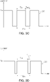
- FIGS. 3A to 3D are diagrams illustrating a waveform of a current pulse applied to a battery in a method for charging and discharging a battery according to an embodiment of the present disclosure.
- FIGS. 3A to 3D may be diagrams illustrating currents input to electrodes of a battery for a charging operation of the battery during an activation process.
- a current pulse 200 may be input to battery electrodes.
- the current pulse 200 may be a square wave current having a predetermined period TP1, unlike a constant current I CC .
- the shape of the current pulse 200 may be variously modified according to embodiments.
- a maximum charging current I CH1 of the current pulse 200 and a duty ratio thereof may be determined.
- the maximum charging current I CH1 of the current pulse 200 may be twice that of the constant current I CC . Therefore, by setting the duty ratio of the current pulse 200 to 50%, the charge amount and discharge amount in the charging operation and the discharging operation using the current pulse 200 may substantially match the charge amount and discharge amount in the charging operation and the discharging operation using the constant current I CC .
- the first time TCH1 for charging the battery and the second time TREST1 for stopping the charging of the battery within one period TP1 may be the same.
- the maximum charging current I CH1 may be twice the constant current I CC . Accordingly, the battery may be charged at the same speed as compared to the case of charging the battery using the constant current I CC .
- since there is a second time T REST1 in which no charging current is input to the battery during the charging operation it is possible to prevent lithium plating, in which lithium ions are excessively moved to the negative electrode of the battery and lithium ions are deposited on a surface of the negative electrode.
- the maximum charging current I CH1 may be set to a value greater than twice the constant current I CC .
- a C-Rate in the charging operation of charging the battery using the current pulse 200 may be greater than a C-Rate in the charging operation of charging the battery using the constant current I CC , and as a result, a time required for the charging operation of the battery may be shortened, and the activation process of the battery may be undertaken faster.
- the C-Rate in the above example may be about 1.5 times the C-Rate in the case of charging the battery with a constant current I CC . Accordingly, it is possible to shorten the time required for charging the battery to the same capacity and reduce the time required for the activation process of the battery.
- the current pulse 210 may have the same maximum charging current I CH1 and duty ratio as in the embodiment described above with reference to FIG. 3A .
- a duty ratio of the current pulse 210 input to the battery electrodes for the charging operation during the activation process may be 50%, and the first time T CH2 and the second time T RES2 may be equal to each other.
- a period TP2 of the current pulse 210 may be different from that in the embodiment shown in FIG. 3A .
- the period TP2 of the current pulse 210 may be 1/2 times the period TP1 of the current pulse 200 in the embodiment shown in FIG. 3A .
- the current pulse 210 may have a frequency twice as high as that of the current pulse 200 according to the embodiment shown in FIG. 3A .
- the battery charge amount thereof may also be substantially the same.
- a duty ratio of a current pulse 220 may be greater than 50%.
- a first time T CH3 at which the current pulse 220 has a maximum charging current I CH2 within a period TP1 of the current pulse 220 may be longer than a second time T REST3 at which the current pulse 220 is not applied and the battery is not charged.
- the maximum charging current I CH2 of the current pulse 220 may be determined by a difference between a first time T CH3 and a second time T REST3 .
- a duty ratio of the current pulse 220 may be 2/3.
- the maximum charging current I CH2 of the current pulse 220 is at a level of 75% of the maximum charging current I CH1 in the embodiments described with reference to FIGS. 3A and 3B above, the charge amount of the battery for the same time may be equal to each other in the embodiments of FIGS. 3A to 3C .
- the charge amount of the battery for the same time may be greater than that in the embodiments of FIGS. 3A and 3B .
- the maximum charging current I CH2 of the current pulse 220 is less than 75% of the maximum charging current I CH1 in the embodiments described with reference to FIGS. 3A and 3B , the charge amount of the battery for the same time may be smaller than that in the embodiments of FIGS. 3A and 3B .
- a duty ratio of the current pulse 230 may be 5/6.
- a length of a first time T CH4 at which the current pulse 230 is input to the battery may be five times a length of a second time T REST4 at which the current pulse 230 is not input to the battery.
- a maximum charging current I CH3 of the current pulse 230 may have to be less than maximum charging currents I CH1 and I CH2 in other embodiments.
- the maximum charging current ICH3 of the current pulse 230 may be reduced to a level of 60% of the maximum charging current ICH1 in the embodiments of FIGS. 3A to 3C .
- a charging current for charging the battery may be input for the first times I CH1 to T CH4 within one period TP1 and TP2, and a charging current may not be input to the battery electrodes for the remaining second time periods T REST1 to T REST4 . Therefore, it is possible to obtain an effect that a rest time is given to the battery for a predetermined time corresponding to the second times (T REST1 to T REST4 ), and the occurrence of lithium plating, in which lithium ions are excessively moved to the negative electrode in the battery and lithium ions are deposited on a surface of the negative electrode may be suppressed.
- a direction in which a charging current flows may be defined as a first direction.
- the charging current can flow from a negative electrode to a positive electrode, and electrons can move from the positive electrode to the negative electrode.
- electrons move from the positive electrode to the negative electrode lithium ions inside the battery may pass through the separator to move to the negative electrode, and the battery can be charged.
- the occurrence of lithium plating may be suppressed by periodically discharging the battery during the charging operation.
- it will be described in more detail with reference to FIG. 4 .
- FIG. 4 is a diagram illustrating a waveform of a current pulse applied to a battery in a battery charging-discharging method according to an embodiment of the present disclosure.
- a current pulse 300 may be input to battery electrodes.
- the current pulse 300 may be a current input to the battery electrodes during a charging operation.
- the current pulse 300 is a square wave current having a predetermined period TP1, and a maximum charging current I CH1 may be input to the battery electrodes for a first time T CH1 by the current pulse 300, and a discharging current I DCH may be input to the battery electrodes.
- a magnitude of the discharging current I DCH may be lower than a magnitude of the maximum charging current I CH1 .
- a battery may be charged during the first time T CH1 during the charging operation of the battery, and a battery may be discharged during the second time T DCH .
- a lithium plating phenomenon occurs in a negative electrode due to the maximum charging current I CH1 input to the battery electrodes during the first time T CH1
- lithium ions on a surface of the negative electrode may be removed for the second time I DCH by the discharging current I DCH .
- the discharging current I DCH may be input to the battery electrodes only in some periods in periods of repetitively appearing current pulses.
- the discharging current I DCH may be input for the second time T DCH only in one period out of N times (N is a natural number greater than or equal to 2), and no current may be input to the battery electrode during the second time T DCH of the remaining periods.
- N is a natural number greater than or equal to 2
- a charging operation of the battery may be undertaken with a current pulse in which the current pulse 200 according to the embodiment described with reference to FIG. 3A and the current pulse 300 according to the embodiment described with reference to FIG. 4 are coupled.
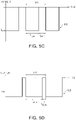
- FIGS. 5A to 5D are diagrams illustrating a waveform of a current pulse applied to a battery in a battery charging-discharging method according to an embodiment of the present disclosure.
- FIGS. 5A to 5D may be diagrams illustrating currents input to electrodes of a battery for a discharging operation of the battery during an activation process.
- a current pulse 400 may be input to battery electrodes. Unlike a constant current I DC , the current pulse 400 may be a square wave current having a predetermined period TP1.
- the discharge amount of the battery may be controlled by a duty ratio and the maximum discharging current I DCH1 of the current pulse 400.
- the maximum discharging current I DCH1 of the current pulse 400 may be twice the constant current I DC .
- the discharge amount of the battery by the current pulse may substantially match the discharge amount of the battery by the constant current I DC .
- the current pulse 410 may have the same maximum discharging current I CH1 and duty ratio as in the embodiment described above with reference to FIG. 5A .
- the duty ratio of the current pulse 410 may be 50%, and the first time T DCH2 and the second time T REST2 may be equal to each other.
- a period TP2 of the current pulse 410 may be 1/2 times the period TP1 in the embodiment shown in FIG. 5A .
- a duty ratio of a current pulse 420 may be variously modified.
- a first time T DCH3 at which the current pulse 420 has a maximum discharging current I DCH2 within one period TP1 of the current pulse 420 may be longer than a second time T REST3 at which discharging of the battery is stopped since the current pulse 420 is not applied to the battery electrodes.
- a discharge amount of the battery may be determined by the maximum discharging current IDCH2 of the current pulse 420 and a difference between the first time T DCH3 and the second time T REST3 .
- the discharge amount of the battery during the same time may be the same in the embodiments in FIGS. 5A to 5C .
- the discharge amount of the battery is also may vary during the same time.
- a duty ratio of the current pulse 430 may be 5/6.
- a length of the first time T DCH4 in which the current pulse 430 is input to the battery may be five times a length of the second time period T REST4 in which the current pulse 230 is not input to the battery.
- a maximum discharging current I DCH3 of the current pulse 430 may have to be less than maximum discharging currents I DCH1 and ID CH2 in other embodiments. For example, by reducing the maximum discharging current I DCH3 of the current pulse 430 to a level of 60% of the maximum discharging current I DCH1 in the embodiments of FIGS. 5A and 5B , the discharge amount of the battery for the same time may be maintained substantially the same as in the embodiments of FIGS. 5A to 5C .
- a direction in which the discharging current flows during the discharging operation may be defined as a second direction opposite to the first direction in which the above-described charging current flows.
- a discharging current can flow from a positive electrode to a negative electrode, and electrons can move from the negative to the positive electrode. Accordingly, lithium ions concentrated on the negative electrode of the battery during the charging operation may pass through a separator inside the battery, and move to the positive electrode during the discharging operation.
- the battery may be periodically charged while the discharging operation is in progress.
- it will be described with reference to FIG. 6 .
- FIG. 6 is a diagram illustrating a waveform of a current pulse applied to a battery in a battery charging-discharging method according to an embodiment of the present disclosure.
- a current pulse 500 may be input to battery electrodes.
- the current pulse 500 is a square wave current having a predetermined period TP1
- a maximum discharging current I DCH1 may be input to the battery electrodes during a first time T DCH1
- a charging current I CH may be input to the battery electrodes during a second time T CH .
- a magnitude of the charging current I CH may be lower than a magnitude of the maximum discharging current I DCH1 .
- a battery may be discharged during the first time T DCH1 , and a battery may be weakly charged during the second time T CH .
- the charging current I CH may be input to the battery electrodes only in some periods in periods of repetitively appearing current pulses.
- the charging current I CH may be input to the battery electrode for the second time T CH only in one period among the N periods (N is a natural number equal to or greater than 2), and a current may not be input to the battery electrodes for the second time T CH of the remaining periods.
- N is a natural number equal to or greater than 2
- a discharging operation of the battery may be undertaken with a current pulse in which the current pulse 400 according to an embodiment described with reference to FIG. 5A and the current pulse 500 according to an embodiment described with reference to FIG. 6 are coupled.
- FIG. 7 is a graph for illustrating a battery charging-discharging method according to an embodiment of the present disclosure.
- FIG. 7 may be a graph illustrating a change in a voltage of a battery during a charging operation of the battery.
- a battery may be charged with a current before a fist time point T1, and the battery may be charged with a voltage after the first time point T1.
- a current pulse may be input to the battery, to move lithium ions from s positive electrode to a negative electrode from an inside of the battery.
- T CC current charging time
- a difference in voltage between the positive electrode and the negative electrode of the battery may increase, and after the first time point T1, when the difference in voltage therebetween increases to a target level (LVT), it can be switched to a charging operation.
- a constant voltage having a constant potential difference to the positive electrode and the negative electrode of the battery during a voltage charging time T CV after a first time point T1.
- a magnitude of the current pulse input to the battery after the first time point T1 may gradually decrease.
- the battery charging/discharging system may end a charging operation for the battery and start a discharging operation. By repeating each of the charging operation and the discharging operation a plurality of times in this manner, an activation process of the battery may be undertaken.
- a time for stopping charging and discharging a battery during a charging process and a discharging process may be secured, or conversely, a time for charging or discharging a battery may be secured. Accordingly, deterioration of the battery may be prevented by suppressing occurrence of lithium plating in which lithium is deposited on a surface of a negative electrode, and minimizing an increase in direct current internal resistance (DCIR).
- DCIR direct current internal resistance
Landscapes
- Engineering & Computer Science (AREA)
- Chemical & Material Sciences (AREA)
- Chemical Kinetics & Catalysis (AREA)
- Electrochemistry (AREA)
- General Chemical & Material Sciences (AREA)
- Manufacturing & Machinery (AREA)
- Power Engineering (AREA)
- Materials Engineering (AREA)
- Secondary Cells (AREA)
- Charge And Discharge Circuits For Batteries Or The Like (AREA)
Applications Claiming Priority (1)
| Application Number | Priority Date | Filing Date | Title |
|---|---|---|---|
| KR20210091952 | 2021-07-14 |
Publications (2)
| Publication Number | Publication Date |
|---|---|
| EP4123776A2 true EP4123776A2 (de) | 2023-01-25 |
| EP4123776A3 EP4123776A3 (de) | 2024-08-07 |
Family
ID=82214116
Family Applications (1)
| Application Number | Title | Priority Date | Filing Date |
|---|---|---|---|
| EP22180553.4A Pending EP4123776A3 (de) | 2021-07-14 | 2022-06-22 | Verfahren zum laden und entladen einer batterie |
Country Status (5)
| Country | Link |
|---|---|
| US (1) | US20230018424A1 (de) |
| EP (1) | EP4123776A3 (de) |
| KR (1) | KR20230011892A (de) |
| CN (1) | CN115621579A (de) |
| WO (1) | WO2024014694A1 (de) |
Families Citing this family (4)
| Publication number | Priority date | Publication date | Assignee | Title |
|---|---|---|---|---|
| EP4394998A4 (de) * | 2022-04-21 | 2025-06-25 | LG Energy Solution, Ltd. | Batteriesteuerungsvorrichtung und batteriesteuerungsverfahren |
| WO2025073030A1 (pt) * | 2023-10-06 | 2025-04-10 | Guacemmi Participações Societárias Ltda. | Método de extrair energia de uma bateria |
| US20260025023A1 (en) * | 2024-07-22 | 2026-01-22 | Enpower Greentech, Inc. | Method to rectify a battery discharge profile of a rechargeable battery |
| KR102850735B1 (ko) | 2025-02-04 | 2025-08-26 | 주식회사티엠프라자 | Pulse 충방전기에서 측정되는 전압 노이즈를 저감하기 위한 전압 노이즈 저감 시스템 |
Family Cites Families (9)
| Publication number | Priority date | Publication date | Assignee | Title |
|---|---|---|---|---|
| US5614805A (en) * | 1992-11-19 | 1997-03-25 | Tokin Corporation | Method and apparatus for charging a secondary battery by supplying pulsed current as charging current |
| US5481174A (en) * | 1993-12-27 | 1996-01-02 | Motorola, Inc. | Method of rapidly charging a lithium ion cell |
| JP3740323B2 (ja) * | 1998-07-31 | 2006-02-01 | キヤノン株式会社 | 二次電池の充電方法及びその装置 |
| WO2002097944A2 (en) * | 2001-05-28 | 2002-12-05 | 10Charge Elektrotechnikai Fejleszto És Kereskedelmi Kft. | Method and apparatus for charging a rechargeable battery with non-liquid electrolyte |
| JP2004236381A (ja) * | 2003-01-28 | 2004-08-19 | Honda Motor Co Ltd | 蓄電池の充放電制御装置および車両用蓄電池の充放電制御装置 |
| DE102011087496A1 (de) * | 2011-11-30 | 2013-06-27 | H-Tech Ag | Verfahren und Vorrichtung zum Laden von wiederaufladbaren Zellen |
| CN102593540B (zh) * | 2012-02-17 | 2015-08-12 | 中兴通讯股份有限公司 | 一种电池激活方法、模块及终端 |
| KR101591931B1 (ko) * | 2013-12-18 | 2016-02-04 | 주식회사 혜령씨엔티 | 2차전지의 활성화 제어 장치 |
| JP6497385B2 (ja) * | 2014-04-24 | 2019-04-10 | 日本電気株式会社 | リチウムイオン二次電池システム及びリチウム二次電池システムの運転方法 |
-
2022
- 2022-06-20 US US17/844,445 patent/US20230018424A1/en active Pending
- 2022-06-22 EP EP22180553.4A patent/EP4123776A3/de active Pending
- 2022-06-23 CN CN202210717143.9A patent/CN115621579A/zh active Pending
- 2022-07-14 KR KR1020220086823A patent/KR20230011892A/ko active Pending
-
2023
- 2023-05-24 WO PCT/KR2023/007098 patent/WO2024014694A1/ko not_active Ceased
Also Published As
| Publication number | Publication date |
|---|---|
| WO2024014694A1 (ko) | 2024-01-18 |
| KR20230011892A (ko) | 2023-01-25 |
| CN115621579A (zh) | 2023-01-17 |
| US20230018424A1 (en) | 2023-01-19 |
| EP4123776A3 (de) | 2024-08-07 |
Similar Documents
| Publication | Publication Date | Title |
|---|---|---|
| EP4123776A2 (de) | Verfahren zum laden und entladen einer batterie | |
| CN102904323B (zh) | 脉波调制充电方法及脉波调制充电装置 | |
| KR101220339B1 (ko) | 직렬연결 배터리 스트링을 위한 자동 전하 균일 방법 및장치 | |
| AU2011250189B2 (en) | Bipolar overvoltage battery pulser and method | |
| CN110313099B (zh) | 对电池进行充电的方法和设备 | |
| CN114303296B (zh) | 电池单体的充电 | |
| JP5953349B2 (ja) | 充電器、および電気システム | |
| CN106816642B (zh) | 电源系统、充放电控制装置及充放电控制方法 | |
| CN104040823A (zh) | 为可充电电池充电的方法和装置 | |
| CN110729520B (zh) | 一种三元电池快速充电方法 | |
| KR20210129097A (ko) | 고용량 유지율 리튬 이온 전지의 충방전 방식 | |
| Gui et al. | A hierarchical active balancing architecture for Li-ion batteries | |
| JP6965770B2 (ja) | 鉛蓄電池の制御装置、鉛蓄電池装置、無停電電源装置、電源システム、及び充電制御方法 | |
| Franco et al. | Current pulse generation methods for li-ion battery chargers | |
| JP2016510480A (ja) | インピーダンスが低減された電気化学セルまたは電池およびその製造方法 | |
| Ghufron et al. | Charging time influence on dynamic lead acid battery capacity with H2SO4 electrolyte | |
| KR20150053181A (ko) | 고주파 컨트롤부를 이용하여 배터리 복원과 충전을 동시에 진행할 수 있는 배터리 충전기의 제어방법 | |
| KR102468985B1 (ko) | 충전 장치 및 그 동작방법 | |
| KR20150053182A (ko) | 고주파 컨트롤부를 이용하여 배터리 복원과 충전을 동시에 진행할 수 있는 배터리 충전기 | |
| RU2410800C2 (ru) | Способ ускоренного формирования и восстановления емкости закрытых никель-кадмиевых аккумуляторов при помощи заряда асимметричным током | |
| CN105406546A (zh) | 充电系统及其充电装置与充电方法 | |
| Li | A High-efficient Battery Charging System for Electric Vehicle | |
| US20250385538A1 (en) | Charging method and charging system for battery cell | |
| Vignan et al. | Implementation of Variable Duty Ratio Reflex Charging of Li-ion Batteries | |
| JP2001339864A (ja) | 鉛蓄電池の充放電制御方法および充放電制御装置 |
Legal Events
| Date | Code | Title | Description |
|---|---|---|---|
| PUAI | Public reference made under article 153(3) epc to a published international application that has entered the european phase |
Free format text: ORIGINAL CODE: 0009012 |
|
| STAA | Information on the status of an ep patent application or granted ep patent |
Free format text: STATUS: THE APPLICATION HAS BEEN PUBLISHED |
|
| AK | Designated contracting states |
Kind code of ref document: A2 Designated state(s): AL AT BE BG CH CY CZ DE DK EE ES FI FR GB GR HR HU IE IS IT LI LT LU LV MC MK MT NL NO PL PT RO RS SE SI SK SM TR |
|
| P01 | Opt-out of the competence of the unified patent court (upc) registered |
Effective date: 20230602 |
|
| PUAL | Search report despatched |
Free format text: ORIGINAL CODE: 0009013 |
|
| AK | Designated contracting states |
Kind code of ref document: A3 Designated state(s): AL AT BE BG CH CY CZ DE DK EE ES FI FR GB GR HR HU IE IS IT LI LT LU LV MC MK MT NL NO PL PT RO RS SE SI SK SM TR |
|
| RIC1 | Information provided on ipc code assigned before grant |
Ipc: H01M 10/052 20100101ALN20240628BHEP Ipc: H02J 7/00 20060101ALI20240628BHEP Ipc: H01M 10/44 20060101ALI20240628BHEP Ipc: H01M 10/04 20060101AFI20240628BHEP |
|
| STAA | Information on the status of an ep patent application or granted ep patent |
Free format text: STATUS: REQUEST FOR EXAMINATION WAS MADE |
|
| 17P | Request for examination filed |
Effective date: 20250206 |
|
| RAP1 | Party data changed (applicant data changed or rights of an application transferred) |
Owner name: SK ON CO., LTD. Owner name: HANA TECHNOLOGY CO., LTD. |