EP4123416B1 - Klappbares funktionsbauteil und elektronisches gerät - Google Patents
Klappbares funktionsbauteil und elektronisches gerät Download PDFInfo
- Publication number
- EP4123416B1 EP4123416B1 EP21772225.5A EP21772225A EP4123416B1 EP 4123416 B1 EP4123416 B1 EP 4123416B1 EP 21772225 A EP21772225 A EP 21772225A EP 4123416 B1 EP4123416 B1 EP 4123416B1
- Authority
- EP
- European Patent Office
- Prior art keywords
- connecting rod
- function component
- functional module
- hinge point
- flip function
- Prior art date
- Legal status (The legal status is an assumption and is not a legal conclusion. Google has not performed a legal analysis and makes no representation as to the accuracy of the status listed.)
- Active
Links
Images

Classifications
-
- F—MECHANICAL ENGINEERING; LIGHTING; HEATING; WEAPONS; BLASTING
- F16—ENGINEERING ELEMENTS AND UNITS; GENERAL MEASURES FOR PRODUCING AND MAINTAINING EFFECTIVE FUNCTIONING OF MACHINES OR INSTALLATIONS; THERMAL INSULATION IN GENERAL
- F16C—SHAFTS; FLEXIBLE SHAFTS; ELEMENTS OR CRANKSHAFT MECHANISMS; ROTARY BODIES OTHER THAN GEARING ELEMENTS; BEARINGS
- F16C11/00—Pivots; Pivotal connections
- F16C11/04—Pivotal connections
-
- F—MECHANICAL ENGINEERING; LIGHTING; HEATING; WEAPONS; BLASTING
- F16—ENGINEERING ELEMENTS AND UNITS; GENERAL MEASURES FOR PRODUCING AND MAINTAINING EFFECTIVE FUNCTIONING OF MACHINES OR INSTALLATIONS; THERMAL INSULATION IN GENERAL
- F16H—GEARING
- F16H37/00—Combinations of mechanical gearings, not provided for in groups F16H1/00 - F16H35/00
- F16H37/12—Gearings comprising primarily toothed or friction gearing, links or levers, and cams, or members of at least two of these types
- F16H37/124—Gearings comprising primarily toothed or friction gearing, links or levers, and cams, or members of at least two of these types for interconverting rotary motion and reciprocating motion
-
- F—MECHANICAL ENGINEERING; LIGHTING; HEATING; WEAPONS; BLASTING
- F16—ENGINEERING ELEMENTS AND UNITS; GENERAL MEASURES FOR PRODUCING AND MAINTAINING EFFECTIVE FUNCTIONING OF MACHINES OR INSTALLATIONS; THERMAL INSULATION IN GENERAL
- F16M—FRAMES, CASINGS OR BEDS OF ENGINES, MACHINES OR APPARATUS, NOT SPECIFIC TO ENGINES, MACHINES OR APPARATUS PROVIDED FOR ELSEWHERE; STANDS; SUPPORTS
- F16M11/00—Stands or trestles as supports for apparatus or articles placed thereon ; Stands for scientific apparatus such as gravitational force meters
- F16M11/02—Heads
- F16M11/04—Means for attachment of apparatus; Means allowing adjustment of the apparatus relatively to the stand
- F16M11/06—Means for attachment of apparatus; Means allowing adjustment of the apparatus relatively to the stand allowing pivoting
- F16M11/10—Means for attachment of apparatus; Means allowing adjustment of the apparatus relatively to the stand allowing pivoting around a horizontal axis
-
- F—MECHANICAL ENGINEERING; LIGHTING; HEATING; WEAPONS; BLASTING
- F16—ENGINEERING ELEMENTS AND UNITS; GENERAL MEASURES FOR PRODUCING AND MAINTAINING EFFECTIVE FUNCTIONING OF MACHINES OR INSTALLATIONS; THERMAL INSULATION IN GENERAL
- F16M—FRAMES, CASINGS OR BEDS OF ENGINES, MACHINES OR APPARATUS, NOT SPECIFIC TO ENGINES, MACHINES OR APPARATUS PROVIDED FOR ELSEWHERE; STANDS; SUPPORTS
- F16M11/00—Stands or trestles as supports for apparatus or articles placed thereon ; Stands for scientific apparatus such as gravitational force meters
- F16M11/02—Heads
- F16M11/18—Heads with mechanism for moving the apparatus relatively to the stand
-
- G—PHYSICS
- G06—COMPUTING OR CALCULATING; COUNTING
- G06F—ELECTRIC DIGITAL DATA PROCESSING
- G06F1/00—Details not covered by groups G06F3/00 - G06F13/00 and G06F21/00
- G06F1/16—Constructional details or arrangements
- G06F1/1613—Constructional details or arrangements for portable computers
- G06F1/1626—Constructional details or arrangements for portable computers with a single-body enclosure integrating a flat display, e.g. Personal Digital Assistants [PDAs]
-
- G—PHYSICS
- G06—COMPUTING OR CALCULATING; COUNTING
- G06F—ELECTRIC DIGITAL DATA PROCESSING
- G06F1/00—Details not covered by groups G06F3/00 - G06F13/00 and G06F21/00
- G06F1/16—Constructional details or arrangements
- G06F1/1613—Constructional details or arrangements for portable computers
- G06F1/1633—Constructional details or arrangements of portable computers not specific to the type of enclosures covered by groups G06F1/1615 - G06F1/1626
- G06F1/1637—Details related to the display arrangement, including those related to the mounting of the display in the housing
- G06F1/1641—Details related to the display arrangement, including those related to the mounting of the display in the housing the display being formed by a plurality of foldable display components
-
- G—PHYSICS
- G06—COMPUTING OR CALCULATING; COUNTING
- G06F—ELECTRIC DIGITAL DATA PROCESSING
- G06F1/00—Details not covered by groups G06F3/00 - G06F13/00 and G06F21/00
- G06F1/16—Constructional details or arrangements
- G06F1/1613—Constructional details or arrangements for portable computers
- G06F1/1633—Constructional details or arrangements of portable computers not specific to the type of enclosures covered by groups G06F1/1615 - G06F1/1626
- G06F1/1675—Miscellaneous details related to the relative movement between the different enclosures or enclosure parts
- G06F1/1677—Miscellaneous details related to the relative movement between the different enclosures or enclosure parts for detecting open or closed state or particular intermediate positions assumed by movable parts of the enclosure, e.g. detection of display lid position with respect to main body in a laptop, detection of opening of the cover of battery compartment
-
- G—PHYSICS
- G06—COMPUTING OR CALCULATING; COUNTING
- G06F—ELECTRIC DIGITAL DATA PROCESSING
- G06F1/00—Details not covered by groups G06F3/00 - G06F13/00 and G06F21/00
- G06F1/16—Constructional details or arrangements
- G06F1/1613—Constructional details or arrangements for portable computers
- G06F1/1633—Constructional details or arrangements of portable computers not specific to the type of enclosures covered by groups G06F1/1615 - G06F1/1626
- G06F1/1675—Miscellaneous details related to the relative movement between the different enclosures or enclosure parts
- G06F1/1681—Details related solely to hinges
-
- G—PHYSICS
- G06—COMPUTING OR CALCULATING; COUNTING
- G06F—ELECTRIC DIGITAL DATA PROCESSING
- G06F1/00—Details not covered by groups G06F3/00 - G06F13/00 and G06F21/00
- G06F1/16—Constructional details or arrangements
- G06F1/1613—Constructional details or arrangements for portable computers
- G06F1/1633—Constructional details or arrangements of portable computers not specific to the type of enclosures covered by groups G06F1/1615 - G06F1/1626
- G06F1/1684—Constructional details or arrangements related to integrated I/O peripherals not covered by groups G06F1/1635 - G06F1/1675
- G06F1/1686—Constructional details or arrangements related to integrated I/O peripherals not covered by groups G06F1/1635 - G06F1/1675 the I/O peripheral being an integrated camera
-
- H—ELECTRICITY
- H04—ELECTRIC COMMUNICATION TECHNIQUE
- H04M—TELEPHONIC COMMUNICATION
- H04M1/00—Substation equipment, e.g. for use by subscribers
- H04M1/02—Constructional features of telephone sets
- H04M1/0202—Portable telephone sets, e.g. cordless phones, mobile phones or bar type handsets
- H04M1/026—Details of the structure or mounting of specific components
- H04M1/0264—Details of the structure or mounting of specific components for a camera module assembly
-
- H—ELECTRICITY
- H04—ELECTRIC COMMUNICATION TECHNIQUE
- H04N—PICTORIAL COMMUNICATION, e.g. TELEVISION
- H04N23/00—Cameras or camera modules comprising electronic image sensors; Control thereof
- H04N23/57—Mechanical or electrical details of cameras or camera modules specially adapted for being embedded in other devices
-
- H—ELECTRICITY
- H04—ELECTRIC COMMUNICATION TECHNIQUE
- H04N—PICTORIAL COMMUNICATION, e.g. TELEVISION
- H04N23/00—Cameras or camera modules comprising electronic image sensors; Control thereof
- H04N23/60—Control of cameras or camera modules
- H04N23/68—Control of cameras or camera modules for stable pick-up of the scene, e.g. compensating for camera body vibrations
- H04N23/681—Motion detection
- H04N23/6812—Motion detection based on additional sensors, e.g. acceleration sensors
-
- H—ELECTRICITY
- H04—ELECTRIC COMMUNICATION TECHNIQUE
- H04N—PICTORIAL COMMUNICATION, e.g. TELEVISION
- H04N23/00—Cameras or camera modules comprising electronic image sensors; Control thereof
- H04N23/60—Control of cameras or camera modules
- H04N23/68—Control of cameras or camera modules for stable pick-up of the scene, e.g. compensating for camera body vibrations
- H04N23/682—Vibration or motion blur correction
- H04N23/685—Vibration or motion blur correction performed by mechanical compensation
-
- H—ELECTRICITY
- H04—ELECTRIC COMMUNICATION TECHNIQUE
- H04N—PICTORIAL COMMUNICATION, e.g. TELEVISION
- H04N23/00—Cameras or camera modules comprising electronic image sensors; Control thereof
- H04N23/60—Control of cameras or camera modules
- H04N23/695—Control of camera direction for changing a field of view, e.g. pan, tilt or based on tracking of objects
-
- F—MECHANICAL ENGINEERING; LIGHTING; HEATING; WEAPONS; BLASTING
- F16—ENGINEERING ELEMENTS AND UNITS; GENERAL MEASURES FOR PRODUCING AND MAINTAINING EFFECTIVE FUNCTIONING OF MACHINES OR INSTALLATIONS; THERMAL INSULATION IN GENERAL
- F16C—SHAFTS; FLEXIBLE SHAFTS; ELEMENTS OR CRANKSHAFT MECHANISMS; ROTARY BODIES OTHER THAN GEARING ELEMENTS; BEARINGS
- F16C2370/00—Apparatus relating to physics, e.g. instruments
-
- F—MECHANICAL ENGINEERING; LIGHTING; HEATING; WEAPONS; BLASTING
- F16—ENGINEERING ELEMENTS AND UNITS; GENERAL MEASURES FOR PRODUCING AND MAINTAINING EFFECTIVE FUNCTIONING OF MACHINES OR INSTALLATIONS; THERMAL INSULATION IN GENERAL
- F16C—SHAFTS; FLEXIBLE SHAFTS; ELEMENTS OR CRANKSHAFT MECHANISMS; ROTARY BODIES OTHER THAN GEARING ELEMENTS; BEARINGS
- F16C2380/00—Electrical apparatus
-
- F—MECHANICAL ENGINEERING; LIGHTING; HEATING; WEAPONS; BLASTING
- F16—ENGINEERING ELEMENTS AND UNITS; GENERAL MEASURES FOR PRODUCING AND MAINTAINING EFFECTIVE FUNCTIONING OF MACHINES OR INSTALLATIONS; THERMAL INSULATION IN GENERAL
- F16H—GEARING
- F16H19/00—Gearings comprising essentially only toothed gears or friction members and not capable of conveying indefinitely-continuing rotary motion
- F16H19/02—Gearings comprising essentially only toothed gears or friction members and not capable of conveying indefinitely-continuing rotary motion for interconverting rotary or oscillating motion and reciprocating motion
- F16H19/04—Gearings comprising essentially only toothed gears or friction members and not capable of conveying indefinitely-continuing rotary motion for interconverting rotary or oscillating motion and reciprocating motion comprising a rack
-
- H—ELECTRICITY
- H04—ELECTRIC COMMUNICATION TECHNIQUE
- H04M—TELEPHONIC COMMUNICATION
- H04M2250/00—Details of telephonic subscriber devices
- H04M2250/20—Details of telephonic subscriber devices including a rotatable camera
Definitions
- the present invention relates to the field of communications technologies, and in particular to a flip function component and an electronic device.
- an electronic device includes an increasing number of functional modules.
- a position of a functional module in the electronic device is usually fixed and cannot be rotated during use, which provides bad experience to a user.
- CN109862145 A discloses portable electronic device comprising a sliding module capable of sliding out a camera module from inside the portable electronic device and a rotating mechanism capable of rotating the camera module for changing the angle between the camera module and the base module.
- CN110166664 A discloses portable electronic device comprising a sliding module capable of sliding out a camera module from inside the portable electronic device and a rotating mechanism capable of rotating the camera module between a front facing position and a rear facing position.
- US2009231484 A1 discloses portable electronic device comprising a rotating mechanism capable of rotating the camera module between a front facing position and a rear facing position.
- CN108989509 A discloses portable electronic device comprising a sliding module capable of sliding out a camera module from inside the portable electronic device.
- a user usually holds the electronic device to shoot an image. Because a user's hand trembles while the user holds the electronic device, and the camera module is in a fixed position relative to the electronic device, hand trembling will cause the camera module to incline. The inclination will cause a change in a viewing angle of a lens, thereby resulting in poor quality of an image shot by the camera module.
- the foregoing problem exists in not only the camera module, but also other functional modules.
- the present invention discloses a flip function component and an electronic device, to resolve a current problem that a functional module in a current electronic device cannot be rotated.
- the present invention adopts the following technical solutions:
- a flip function component applied to an electronic device, where the electronic device includes an installation base, and the flip function component includes a driving mechanism, a connecting rod transmission mechanism, and a functional module, where the driving mechanism includes a first driving portion, and the connecting rod transmission mechanism includes a first connecting rod and a second connecting rod, where a first end of the first connecting rod is connected to the first driving portion, a second end of the first connecting rod is hinged to the functional module, and a hinge point between the second end of the first connecting rod and the functional module is a first hinge point, a first end of the second connecting rod is hinged to the installation base, and a hinge point between the first end of the second connecting rod and the installation base is a second hinge point, a second end of the second connecting rod is hinged to the functional module, and a hinge point between the second end of the second connecting rod and the functional module is a third hinge point; and the first driving portion drives the first connecting rod to move, to enable the second connecting rod to drive the functional module to rotate.
- An electronic device including the foregoing flip function component.
- the first driving portion pushes the functional module to move
- the first connecting rod and the second connecting rod cooperate to enable the functional module to rotate, so that the functional module can be flipped.
- the functional module can be rotated to different angles for working, so as to implement rotation of the functional module, thereby improving user experience.
- embodiments of the present invention disclose a flip function component, which is applied to an electronic device.
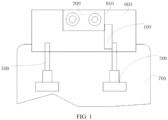
- the disclosed flip function component includes a driving mechanism, a connecting rod transmission mechanism 100, and a functional module 200.
- the driving mechanism includes a first driving portion 300, and the first driving portion 300 may be a stepping motor.
- the connecting rod transmission mechanism 100 includes a first connecting rod 110 and a second connecting rod 120. Specifically, a first end of the first connecting rod 110 is connected to the first driving portion 300, and the first driving portion 300 can drive the first connecting rod 110 to move. A second end of the first connecting rod 110 is hinged to the functional module 200.
- the electronic device includes an installation base, a first end of the second connecting rod 120 is hinged to the installation base, and a second end of the second connecting rod 120 is hinged to the functional module 200.
- the installation base may be a housing 700 of the electronic device, or may be a telescopic module movably disposed on the housing 700, which is not limited in this embodiment of the present invention.
- a hinge point between the second end of the first connecting rod 110 and the functional module 200 is a first hinge point 410.
- a hinge point between the first end of the second connecting rod 120 and the installation base is a second hinge point 420.
- a hinge point between the second end of the second connecting rod 120 and the functional module 200 is a third hinge point 430.
- the first hinge point 410, the second hinge point 420, and the third hinge point 430 are arranged at intervals.
- the first driving portion 300 drives the first connecting rod 110 to move
- the first connecting rod 110 pushes the functional module 200 to move.
- the functional module 200 is hinged to the second end of the second connecting rod 120, the functional module 200 pushes the second connecting rod 120 to rotate around the second hinge point 420.
- the functional module 200 is also pulled by the second connecting rod 120 during movement, so that the functional module 200 can rotate around the first hinge point 410 under the action of a pulling force, and then the functional module 200 can be flipped.
- the first driving portion 300 pushes the functional module 200 to move
- the first connecting rod 110 and the second connecting rod 120 cooperate to enable the functional module 200 to rotate, so that the functional module 200 can be flipped.
- the functional module 200 can be rotated to different angles for working, so as to implement rotation of the functional module 200, thereby improving user experience.
- the functional module 200 may include at least one of a camera module, a card tray, a light supplementing module, a fingerprint recognizing module, a USB interface, and a telephone receiver.
- the functional module 200 may be a camera module.
- the camera module only needs to be provided with one camera.
- the camera module can be flipped during working, so that the camera can be used as a front camera of the electronic device, and can be also used as a rear camera of the electronic device, thereby not only providing relatively good shooting experience to the user, but also saving manufacturing costs for the electronic device.
- the flip function component may further include an angle detector and a control apparatus.
- the angle detector (such as a gyroscope) can detect an inclination angle and inclination direction of the camera module due to trembling during shooting, and feed back the inclination angle and inclination direction to the control apparatus.
- the control apparatus may be a CPU (Central Processing Unit), the control apparatus determines a compensation angle and compensation direction according to the inclination direction and inclination angle of the camera module, and controls the first driving portion 300 to drive the camera module to rotate at the compensation angle along the compensation direction.
- the compensation angle is equal to the inclination angle
- the compensation direction is opposite to the inclination direction.
- the angle detector can detect an inclination angle generated by the camera module. Further, the control apparatus controls, according to the inclination angle generated by the camera module, the first driving portion 300 to move, so that the camera module rotates along a direction opposite to the inclination direction during shooting, and then the camera module can be returned to an original working position. Finally, a shooting process of the camera module is not easily affected by trembling of the user's hand or another reason, thereby improving shooting experience of the user.
- the connecting rod transmission mechanism 100 may be directly connected to a module body 210 of the functional module 200, so that the module body 210 can be flipped.
- the functional module 200 may further include a clamping portion 220, the module body 210 may be fixed to the clamping portion 220, and the second end of the first connecting rod 110 may be hinged to the clamping portion 220.
- a hinge point between the second end of the first connecting rod 110 and the clamping portion 220 may be the first hinge point 410
- the second end of the second connecting rod 120 may be hinged to the clamping portion 220
- a hinge point between the second end of the second connecting rod 120 and the clamping portion 220 may be the third hinge point 430.
- the first driving portion 300 and the connecting rod transmission mechanism 100 can drive the clamping portion 220 to flip, so that the clamping portion 220 drives the module body 210 to flip, and finally implementing flipping of the functional module 200.
- module body 210 Compared with that the connecting rod transmission mechanism 100 is directly connected to the module body 210 of the functional module 200, in this manner, there is no need to dispose a corresponding connection mechanism on the module body 210, so that the module body 210 is relatively complete.
- different types of module bodies 210 can be disposed on the clamping portion 220, so that the flip function component has a better function.
- the clamping portion 220 may have a groove.
- the groove may include two opposite clamping surfaces 221, and clamping space is formed between the two opposite clamping surfaces 221.
- at least a part of the module body 210 may be disposed between the two clamping surfaces 221. That is, at least a part of the module body 210 may be in the clamping space.
- the clamping portion 220 of this structure not only facilitates processing and forming, but also has better reliability, thereby enabling connection between the functional module 200 and the connecting rod transmission mechanism 100 to be firmer.
- the clamping portion 220 may be an elastic piece, and the module body 210 may be elastically clamped between the two clamping surfaces 221, so that at least a part of the module body 210 can be stably located between the two clamping surfaces 221 under the action of an elastic force, so as to prevent the module body 210 from being inclined during working.
- At least one clamping surface 221 may be provided with a tooth-shaped protrusion 221a.
- one of the clamping surfaces 221 may be provided with the tooth-shaped protrusion 221a; or both clamping surfaces 221 may be provided with the tooth-shaped protrusion 221a, and at least a part of the module body 210 may be detachably disposed between the two clamping surfaces 221 through the tooth-shaped protrusion 221a.
- the tooth-shaped protrusion 221a can better contact at least a part of an outer surface of the module body 210, the module body 210 can be stably fixed between the two clamping surfaces 221 to prevent the module body 210 from being inclined during working.
- the module body 210 is detachably disposed between the two clamping surfaces 221, which facilitates replacement of different types of module bodies 210, and the functional module 200 is not required to be dismantled entirely, which can undoubtedly reduce assembly and disassembly procedures.
- the first driving portion 300 may have multiple types.
- the first driving portion 300 may be a linear motor, and the first driving portion 300 may also be a rotary motor.
- the first driving portion 300 may be the rotary motor.
- the connecting rod transmission mechanism 100 may further include a threaded bushing 130, and the first end of the first connecting rod 110 may include a threaded segment 111.
- the threaded bushing 130 may be sleeved on the threaded segment 111, the threaded bushing 130 may be engaged with the threaded segment 111, and the rotary motor may be connected to the threaded bushing 130.
- the rotary motor can drive the threaded bushing 130 to rotate. Since the threaded bushing 130 is engaged with the threaded segment 111, the threaded bushing 130 can drive, while rotating, the first connecting rod 110 to move, and finally the functional module 200 can be driven, through the moving first connecting rod 110, to rotate.
- the connecting rod transmission mechanism 100 can be driven more accurately to move, so that the functional module 200 can be flipped relatively accurately, and advantages of long life and high efficiency are provided in this manner.
- the connecting rod transmission mechanism 100 may include a gear
- the first end of the first connecting rod 110 may include a rack segment
- the rotary motor may be connected to the gear
- the gear may be engaged with the rack segment.
- the rotary motor can drive the gear to rotate. Since the gear is engaged with the rack segment, a rotating gear can drive the first connecting rod 110 to move, and finally the functional module 200 can be driven, through the moving first connecting rod 110, to rotate. In this manner, not only can the functional module 200 be flipped more accurately, but also a structure of the flip function component can be relatively compact.
- an embodiment of the present invention further discloses an electronic device, and the disclosed electronic device includes the flip function component described in any one of the foregoing embodiments.
- the flip function component can be installed on the electronic device in multiple manners.
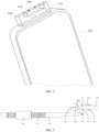
- the electronic device may include an installation support 600 disposed on the housing 700.
- the installation support 600 may be the foregoing installation base, and the flip function component may be disposed on the installation support 600.
- the installation support 600 can provide an installation position for the flip function component, so that a structure of the electronic device can be relatively compact.
- the flip function component may be installed on the installation support 600 first, and then both the flip function component and the installation support 600 may be entirely installed on the housing 700 of the electronic device.
- the installation support 600 may be movably disposed on the housing 700.
- the driving mechanism may further include a second driving portion 500.
- the housing 700 may have an inner cavity and an opening 710 communicating with the inner cavity.
- the second driving portion 500 may be connected to the installation support 600, and the second driving portion 500 can drive the installation support 600 to move, so that at least a part of the functional module 200 can extend out of the housing 700 through the opening 710 along with the installation support 600, or the functional module 200 can be retracted into housing 700 through the opening 710 along with the installation support 600.
- the functional module 200 when the functional module 200 needs to work, the functional module 200 can extend out of the housing 700 through the opening 710 along with movement of the installation support 600 for working, thereby improving flexibility of the functional module 200; and after the functional module 200 completes work, the functional module 200 can be retracted into the housing 700 through the opening 710 along with the movement of the installation support 600, thereby providing waterproof and dustproof effects for the functional module 200 and other members of the flip functional component.
- an avoidance groove 610 may be disposed at the installation support 600.
- the functional module 200 can be flipped in the avoidance groove 610, so that the functional module 200 can be flipped more easily.
- the avoidance groove 610 also enables the functional module 200 to be at least partially outside the installation support 600, thereby facilitating the functional module 200 to work.
- the electronic device disclosed in the embodiments of the present invention may be a smart phone, a tablet computer, an e-book reader, a wearable device, and the like. Moreover, the electronic device may also be other devices, and the embodiments of the present invention do not limit specific types of the electronic device.
Landscapes
- Engineering & Computer Science (AREA)
- General Engineering & Computer Science (AREA)
- Theoretical Computer Science (AREA)
- Computer Hardware Design (AREA)
- Physics & Mathematics (AREA)
- General Physics & Mathematics (AREA)
- Human Computer Interaction (AREA)
- Mechanical Engineering (AREA)
- Signal Processing (AREA)
- Multimedia (AREA)
- Studio Devices (AREA)
- Telephone Set Structure (AREA)
- Accessories Of Cameras (AREA)
- Structure And Mechanism Of Cameras (AREA)
- Adjustment Of Camera Lenses (AREA)
Claims (10)
- Klappbares Funktionsbauteil, ausgeführt von einem elektronischen Gerät, wobei das elektronische Gerät eine Installationsbasis umfasst, das klappbare Funktionsbauteil einen Antriebsmechanismus, einen Verbindungsstangenübertragungsmechanismus (100) und ein Funktionsmodul (200) umfasst, wobei der Antriebsmechanismus einen ersten Antriebsabschnitt (300) umfasst und der Verbindungsstangenübertragungsmechanismus (100) eine erste Verbindungsstange (110) und eine zweite Verbindungsstange (120) umfasst, wobei ein erstes Ende der ersten Verbindungsstange (110) mit dem ersten Antriebsabschnitt (300) verbunden ist, dadurch gekennzeichnet, dass:ein zweites Ende der ersten Verbindungsstange (110) drehgelenkig an dem Funktionsmodul (200) angebracht ist und ein Gelenkpunkt zwischen dem zweiten Ende der ersten Verbindungsstange (110) und dem Funktionsmodul (200) ein erster Gelenkpunkt (410) ist, ein erstes Ende der zweiten Verbindungsstange (120) drehgelenkig an der Installationsbasis angebracht ist, ein Gelenkpunkt zwischen dem ersten Ende der zweiten Verbindungsstange (120) und der Installationsbasis ein zweiter Gelenkpunkt (420) ist, ein zweites Ende der zweiten Verbindungsstange (120) drehgelenkig an dem Funktionsmodul (200) angebracht ist, und ein Gelenkpunkt zwischen dem zweiten Ende der zweiten Verbindungsstange (120) und dem Funktionsmodul (200) ein dritter Gelenkpunkt (430) ist; undder erste treibende Abschnitt (300) die erste Verbindungsstange (110) antreibt, sodass sie sich bewegt, um die zweite Verbindungsstange (120) zu befähigen, das Funktionsmodul (200) anzutreiben, sodass es sich dreht.
- Klappbares Funktionsbauteil nach Anspruch 1, wobei das Funktionsmodul (200) ein Kameramodul ist.
- Klappbares Funktionsbauteil nach Anspruch 2, wobei das klappbare Funktionsbauteil ferner einen Winkeldetektor und eine Steuervorrichtung umfasst, wobei der Winkeldetektor einen Neigungswinkel und eine Neigungsrichtung des Kameramoduls während Aufnahmen erkennt und die Steuervorrichtung den ersten Antriebsabschnitt (300) steuert, um den ersten Antriebsabschnitt (300) zu befähigen, das Kameramodul anzutreiben, damit es sich in einem Ausgleichswinkel entlang einer Ausgleichsrichtung dreht, wobei der Ausgleichswinkel gleich dem Neigungswinkel ist und die Ausgleichsrichtung der Neigungsrichtung entgegengesetzt ist.
- Klappbares Funktionsbauteil nach Anspruch 1, wobei das Funktionsmodul (200) einen Modulkörper (210) und einen Klemmabschnitt (220) umfasst, wobei der Modulkörper (210) an dem Klemmabschnitt (220) befestigt ist, das zweite Ende der ersten Verbindungsstange (110) drehgelenkig an dem Klemmabschnitt (220) angebracht ist, ein Gelenkpunkt zwischen dem zweiten Ende der ersten Verbindungsstange (110) und dem Klemmabschnitt (220) der erste Gelenkpunkt (410) ist, das zweite Ende der zweiten Verbindungsstange (120) drehgelenkig am Klemmabschnitt (220) angebracht ist, und ein Gelenkpunkt zwischen dem zweiten Ende der zweiten Verbindungsstange (120) und dem Klemmabschnitt (220) der dritte Gelenkpunkt (430) ist.
- Klappbares Funktionsbauteil nach Anspruch 4, wobei der Klemmabschnitt (220) eine Nut aufweist, die Nut zwei einander gegenüberliegende Klemmflächen (221) umfasst und mindestens ein Teil des Modulkörpers (210) zwischen den zwei Klemmflächen (221) angeordnet ist.
- Klappbares Funktionsbauteil nach Anspruch 5, wobei ein zahnförmiger Vorsprung (221a) auf mindestens einer der Klemmflächen (221) angeordnet ist und mindestens ein Teil des Modulkörpers (210) lösbar zwischen den zwei Klemmflächen (221) durch den zahnförmigen Vorsprung (221a) angeordnet ist.
- Klappbares Funktionsbauteil nach Anspruch 1, wobei der erste Antriebsabschnitt (300) ein Drehmotor ist, der Verbindungsstangenübertragungsmechanismus (100) ferner eine Gewindebuchse (130) umfasst, das erste Ende der ersten Verbindungsstange (110) ein Gewindesegment (111) umfasst, die Gewindebuchse (130) hülsenartig auf das Gewindesegment (111) aufgesetzt ist, der Drehmotor mit der Gewindebuchse (130) verbunden ist, und der Drehmotor die Gewindebuchse (130) antreibt, sodass sie sich dreht, um die erste Verbindungsstange (110) zu befähigen, sich zu bewegen.
- Klappbares Funktionsbauteil nach Anspruch 1, wobei der erste Antriebsabschnitt (300) ein Drehmotor ist, der Verbindungsstangenübertragungsmechanismus (100) ein Zahnrad umfasst und das erste Ende der ersten Verbindungsstange (110) ein Zahnstangensegment umfasst, wobei der Drehmotor mit dem Zahnrad verbunden ist, sich das Zahnrad im Eingriff mit dem Zahnstangensegment befindet und der Drehmotor das Zahnrad antreibt, sodass es sich dreht, um die erste Verbindungsstange (110) zu befähigen, sich zu bewegen.
- Elektronische Vorrichtung, umfassend das klappbare Funktionsbauteil nach einem der Ansprüche 1 bis 8.
- Elektronische Vorrichtung nach Anspruch 9, wobei die elektronische Vorrichtung ein Gehäuse (700) und eine bewegbar an dem Gehäuse (700) angebrachte Installationsauflage (600) umfasst, wobei die Installationsauflage (600) die Installationsbasis ist, der Antriebsmechanismus ferner einen zweiten Antriebsabschnitt (500) umfasst und das Gehäuse (700) einen inneren Hohlraum und eine Öffnung (710) im Austausch mit dem inneren Hohlraum aufweist, wobei der zweite Antriebsabschnitt (500) mit der Installationsauflage (600) verbunden ist, das klappbare Funktionsbauteil an der Installationsauflage (600) angeordnet ist, der zweite Antriebsabschnitt (500) die Installationsauflage (600) antreibt, sodass sie sich bewegt, und das Funktionsmodul (200) durch die Öffnung (710) zusammen mit der Installationsauflage (600) in das Gehäuse (700) zurückgezogen ist oder sich zumindest teilweise aus dem Gehäuse (700) erstreckt.
Applications Claiming Priority (2)
| Application Number | Priority Date | Filing Date | Title |
|---|---|---|---|
| CN202010191136.0A CN111427419B (zh) | 2020-03-18 | 2020-03-18 | 翻转功能组件及电子设备 |
| PCT/CN2021/080819 WO2021185207A1 (zh) | 2020-03-18 | 2021-03-15 | 翻转功能组件及电子设备 |
Publications (3)
| Publication Number | Publication Date |
|---|---|
| EP4123416A1 EP4123416A1 (de) | 2023-01-25 |
| EP4123416A4 EP4123416A4 (de) | 2023-09-20 |
| EP4123416B1 true EP4123416B1 (de) | 2024-08-07 |
Family
ID=71549536
Family Applications (1)
| Application Number | Title | Priority Date | Filing Date |
|---|---|---|---|
| EP21772225.5A Active EP4123416B1 (de) | 2020-03-18 | 2021-03-15 | Klappbares funktionsbauteil und elektronisches gerät |
Country Status (7)
| Country | Link |
|---|---|
| US (1) | US12326762B2 (de) |
| EP (1) | EP4123416B1 (de) |
| JP (1) | JP7437526B2 (de) |
| KR (1) | KR102728082B1 (de) |
| CN (1) | CN111427419B (de) |
| ES (1) | ES2987301T3 (de) |
| WO (1) | WO2021185207A1 (de) |
Families Citing this family (4)
| Publication number | Priority date | Publication date | Assignee | Title |
|---|---|---|---|---|
| CN111427419B (zh) | 2020-03-18 | 2021-11-23 | 维沃移动通信有限公司 | 翻转功能组件及电子设备 |
| CN113370907B (zh) * | 2021-06-08 | 2022-03-29 | 中国电子科技集团公司第三十八研究所 | 一种电子设备的伸缩翻转装置 |
| CN115343896B (zh) * | 2022-08-10 | 2024-07-26 | 维沃移动通信有限公司 | 电子设备和电子设备的控制方法及控制装置 |
| CN115325360B (zh) * | 2022-09-05 | 2024-09-06 | 江苏月达科技有限公司 | 一种全方位小区智能监控系统 |
Family Cites Families (30)
| Publication number | Priority date | Publication date | Assignee | Title |
|---|---|---|---|---|
| JP2528666Y2 (ja) * | 1991-08-09 | 1997-03-12 | 宇宙開発事業団 | カメラ雲台 |
| JP2000171845A (ja) | 1998-12-02 | 2000-06-23 | Mitsubishi Electric Corp | 撮像装置 |
| JP2003125050A (ja) * | 2001-10-15 | 2003-04-25 | Strawberry Corporation | ヒンジ装置並びにヒンジ装置を用いた電子機器 |
| TW200806006A (en) * | 2006-07-14 | 2008-01-16 | Compal Communications Inc | Electrical apparatus with image-capturing device |
| TWI383674B (zh) * | 2008-03-11 | 2013-01-21 | Quanta Comp Inc | 影像擷取裝置 |
| JP2010155484A (ja) | 2008-12-26 | 2010-07-15 | Kanto Auto Works Ltd | バックガイドモニターカメラ装置 |
| JP2011027185A (ja) | 2009-07-27 | 2011-02-10 | Tamagawa Seiki Co Ltd | 回転直動変換機構 |
| CN105905046A (zh) * | 2016-06-14 | 2016-08-31 | 广东康盈交通设备制造有限公司 | 一种改进的车载折叠结构 |
| CN107197133B (zh) | 2017-07-21 | 2019-11-29 | 维沃移动通信有限公司 | 一种移动终端及摄像头组件 |
| US10498869B2 (en) * | 2017-10-24 | 2019-12-03 | Guangdong Oppo Mobile Telecommunications Corp., Ltd. | Mobile terminal and electronic device |
| CN109862145B (zh) * | 2017-11-30 | 2021-03-09 | Oppo广东移动通信有限公司 | 功能组件、移动终端及移动终端的控制方法 |
| CN207968576U (zh) * | 2018-02-09 | 2018-10-12 | 广东欧珀移动通信有限公司 | 手机 |
| CN207926665U (zh) * | 2018-02-09 | 2018-09-28 | 广东欧珀移动通信有限公司 | 移动终端 |
| CN207910858U (zh) * | 2018-02-09 | 2018-09-25 | 广东欧珀移动通信有限公司 | 手机 |
| CN114785926B (zh) * | 2018-02-13 | 2023-10-24 | Oppo广东移动通信有限公司 | 一种电子设备 |
| CN110198367B (zh) * | 2018-02-26 | 2020-09-04 | Oppo广东移动通信有限公司 | 一种电子装置及一种电子装置的拍照控制方法 |
| CN108989509B (zh) * | 2018-08-28 | 2021-01-08 | 维沃移动通信有限公司 | 一种终端设备 |
| KR102471644B1 (ko) * | 2018-11-09 | 2022-11-29 | 삼성전자주식회사 | 팝업 회전 카메라 및 그것을 포함하는 전자 장치 |
| KR102106296B1 (ko) * | 2018-11-29 | 2020-05-04 | 삼성전자주식회사 | 카메라를 포함하는 전자 장치 및 그것의 동작 방법 |
| CN209572070U (zh) * | 2018-11-30 | 2019-11-01 | Oppo广东移动通信有限公司 | 传动模组、传动机构、摄像头组合件和移动终端 |
| CN109873938B (zh) * | 2019-02-18 | 2021-07-30 | 维沃移动通信(杭州)有限公司 | 终端设备 |
| KR102648987B1 (ko) * | 2019-04-09 | 2024-03-19 | 삼성전자 주식회사 | 회전 카메라를 포함하는 전자장치 |
| KR102619948B1 (ko) * | 2019-04-09 | 2024-01-03 | 삼성전자주식회사 | 회전식 광학 모듈을 포함하는 전자 장치 |
| CN110099200B (zh) | 2019-04-23 | 2020-08-07 | 瑞声光电科技(常州)有限公司 | 摄像装置、电子设备及电子设备的使用方法 |
| CN111866227B (zh) * | 2019-04-28 | 2021-12-03 | 北京小米移动软件有限公司 | 终端设备 |
| KR102660800B1 (ko) * | 2019-07-02 | 2024-04-26 | 삼성전자주식회사 | 회전 카메라를 포함하는 전자 장치 |
| KR102758630B1 (ko) * | 2019-07-08 | 2025-01-22 | 삼성전자주식회사 | 카메라 모듈을 포함하는 전자 장치 |
| CN112398974A (zh) * | 2019-08-15 | 2021-02-23 | 北京小米移动软件有限公司 | 摄像头模组、终端设备及拍摄方法 |
| CN110673656B (zh) * | 2019-09-30 | 2024-03-26 | 维沃移动通信有限公司 | 摄像模组、电子设备及摄像模组的控制方法 |
| CN111427419B (zh) * | 2020-03-18 | 2021-11-23 | 维沃移动通信有限公司 | 翻转功能组件及电子设备 |
-
2020
- 2020-03-18 CN CN202010191136.0A patent/CN111427419B/zh active Active
-
2021
- 2021-03-15 EP EP21772225.5A patent/EP4123416B1/de active Active
- 2021-03-15 ES ES21772225T patent/ES2987301T3/es active Active
- 2021-03-15 WO PCT/CN2021/080819 patent/WO2021185207A1/zh not_active Ceased
- 2021-03-15 KR KR1020227035916A patent/KR102728082B1/ko active Active
- 2021-03-15 JP JP2022556500A patent/JP7437526B2/ja active Active
-
2022
- 2022-09-16 US US17/946,604 patent/US12326762B2/en active Active
Also Published As
| Publication number | Publication date |
|---|---|
| EP4123416A4 (de) | 2023-09-20 |
| CN111427419A (zh) | 2020-07-17 |
| JP7437526B2 (ja) | 2024-02-22 |
| WO2021185207A1 (zh) | 2021-09-23 |
| US20230011523A1 (en) | 2023-01-12 |
| ES2987301T3 (es) | 2024-11-14 |
| KR102728082B1 (ko) | 2024-11-11 |
| US12326762B2 (en) | 2025-06-10 |
| JP2023518282A (ja) | 2023-04-28 |
| CN111427419B (zh) | 2021-11-23 |
| EP4123416A1 (de) | 2023-01-25 |
| KR20220156033A (ko) | 2022-11-24 |
Similar Documents
| Publication | Publication Date | Title |
|---|---|---|
| EP4123416B1 (de) | Klappbares funktionsbauteil und elektronisches gerät | |
| EP4343426A1 (de) | Irisblende, kameramodul und elektronische vorrichtung | |
| KR102185056B1 (ko) | 카메라 모듈 | |
| WO2021063243A1 (zh) | 摄像模组及电子设备 | |
| US11343365B2 (en) | Electronic device with flexible expandable display | |
| US10704732B2 (en) | Horizontal posture maintaining device and posture maintaining device driving method | |
| KR100919987B1 (ko) | 소형 디지탈 줌 카메라 및, 그것을 구비한 휴대 전화 | |
| EP3751383A1 (de) | Faltvorrichtung, anzeigebildschirmmodul und mobiles endgerät | |
| WO2021063231A1 (zh) | 摄像模组及电子设备 | |
| CN104618542A (zh) | 手机 | |
| CN112073621B (zh) | 摄像模组和电子设备 | |
| EP4579330A1 (de) | Irisblende, kameramodul und elektronische vorrichtung | |
| WO2021147912A1 (zh) | 摄像模组、电子设备及摄像模组的控制方法 | |
| CN213637901U (zh) | 电子设备 | |
| US11385523B2 (en) | Optical assembly driving apparatus, imaging apparatus and portable electronic device | |
| CN110336900A (zh) | 摄像头模组及移动终端 | |
| CN110381256A (zh) | 终端设备及其控制方法和控制装置、计算机可读存储介质 | |
| CN112351157B (zh) | 摄像模组及移动终端 | |
| EP3972228B1 (de) | Endgerät | |
| CN214544446U (zh) | 驱动装置、摄像模组及电子设备 | |
| CN209570873U (zh) | 一种电子设备 | |
| CN217883557U (zh) | 一种摄像装置及电子设备 | |
| CN223885269U (zh) | 摄像模组及电子设备 | |
| CN216356795U (zh) | 一种移动终端及其摄像头装置 | |
| EP4586046A1 (de) | Scharniermodul und elektronische vorrichtung damit |
Legal Events
| Date | Code | Title | Description |
|---|---|---|---|
| STAA | Information on the status of an ep patent application or granted ep patent |
Free format text: STATUS: THE INTERNATIONAL PUBLICATION HAS BEEN MADE |
|
| PUAI | Public reference made under article 153(3) epc to a published international application that has entered the european phase |
Free format text: ORIGINAL CODE: 0009012 |
|
| STAA | Information on the status of an ep patent application or granted ep patent |
Free format text: STATUS: REQUEST FOR EXAMINATION WAS MADE |
|
| 17P | Request for examination filed |
Effective date: 20221017 |
|
| AK | Designated contracting states |
Kind code of ref document: A1 Designated state(s): AL AT BE BG CH CY CZ DE DK EE ES FI FR GB GR HR HU IE IS IT LI LT LU LV MC MK MT NL NO PL PT RO RS SE SI SK SM TR |
|
| DAV | Request for validation of the european patent (deleted) | ||
| DAX | Request for extension of the european patent (deleted) | ||
| A4 | Supplementary search report drawn up and despatched |
Effective date: 20230821 |
|
| RIC1 | Information provided on ipc code assigned before grant |
Ipc: H04M 1/02 20060101ALI20230814BHEP Ipc: F16C 11/04 20060101ALI20230814BHEP Ipc: G06F 1/16 20060101AFI20230814BHEP |
|
| GRAP | Despatch of communication of intention to grant a patent |
Free format text: ORIGINAL CODE: EPIDOSNIGR1 |
|
| STAA | Information on the status of an ep patent application or granted ep patent |
Free format text: STATUS: GRANT OF PATENT IS INTENDED |
|
| INTG | Intention to grant announced |
Effective date: 20240424 |
|
| GRAS | Grant fee paid |
Free format text: ORIGINAL CODE: EPIDOSNIGR3 |
|
| GRAA | (expected) grant |
Free format text: ORIGINAL CODE: 0009210 |
|
| STAA | Information on the status of an ep patent application or granted ep patent |
Free format text: STATUS: THE PATENT HAS BEEN GRANTED |
|
| AK | Designated contracting states |
Kind code of ref document: B1 Designated state(s): AL AT BE BG CH CY CZ DE DK EE ES FI FR GB GR HR HU IE IS IT LI LT LU LV MC MK MT NL NO PL PT RO RS SE SI SK SM TR |
|
| REG | Reference to a national code |
Ref country code: GB Ref legal event code: FG4D |
|
| REG | Reference to a national code |
Ref country code: CH Ref legal event code: EP |
|
| REG | Reference to a national code |
Ref country code: DE Ref legal event code: R096 Ref document number: 602021016952 Country of ref document: DE |
|
| REG | Reference to a national code |
Ref country code: IE Ref legal event code: FG4D |
|
| REG | Reference to a national code |
Ref country code: NL Ref legal event code: FP |
|
| REG | Reference to a national code |
Ref country code: ES Ref legal event code: FG2A Ref document number: 2987301 Country of ref document: ES Kind code of ref document: T3 Effective date: 20241114 |
|
| REG | Reference to a national code |
Ref country code: LT Ref legal event code: MG9D |
|
| PG25 | Lapsed in a contracting state [announced via postgrant information from national office to epo] |
Ref country code: NO Free format text: LAPSE BECAUSE OF FAILURE TO SUBMIT A TRANSLATION OF THE DESCRIPTION OR TO PAY THE FEE WITHIN THE PRESCRIBED TIME-LIMIT Effective date: 20241107 |
|
| REG | Reference to a national code |
Ref country code: AT Ref legal event code: MK05 Ref document number: 1711659 Country of ref document: AT Kind code of ref document: T Effective date: 20240807 |
|
| PG25 | Lapsed in a contracting state [announced via postgrant information from national office to epo] |
Ref country code: GR Free format text: LAPSE BECAUSE OF FAILURE TO SUBMIT A TRANSLATION OF THE DESCRIPTION OR TO PAY THE FEE WITHIN THE PRESCRIBED TIME-LIMIT Effective date: 20241108 Ref country code: FI Free format text: LAPSE BECAUSE OF FAILURE TO SUBMIT A TRANSLATION OF THE DESCRIPTION OR TO PAY THE FEE WITHIN THE PRESCRIBED TIME-LIMIT Effective date: 20240807 Ref country code: PL Free format text: LAPSE BECAUSE OF FAILURE TO SUBMIT A TRANSLATION OF THE DESCRIPTION OR TO PAY THE FEE WITHIN THE PRESCRIBED TIME-LIMIT Effective date: 20240807 Ref country code: PT Free format text: LAPSE BECAUSE OF FAILURE TO SUBMIT A TRANSLATION OF THE DESCRIPTION OR TO PAY THE FEE WITHIN THE PRESCRIBED TIME-LIMIT Effective date: 20241209 |
|
| PG25 | Lapsed in a contracting state [announced via postgrant information from national office to epo] |
Ref country code: BG Free format text: LAPSE BECAUSE OF FAILURE TO SUBMIT A TRANSLATION OF THE DESCRIPTION OR TO PAY THE FEE WITHIN THE PRESCRIBED TIME-LIMIT Effective date: 20240807 |
|
| PG25 | Lapsed in a contracting state [announced via postgrant information from national office to epo] |
Ref country code: LV Free format text: LAPSE BECAUSE OF FAILURE TO SUBMIT A TRANSLATION OF THE DESCRIPTION OR TO PAY THE FEE WITHIN THE PRESCRIBED TIME-LIMIT Effective date: 20240807 |
|
| PG25 | Lapsed in a contracting state [announced via postgrant information from national office to epo] |
Ref country code: AT Free format text: LAPSE BECAUSE OF FAILURE TO SUBMIT A TRANSLATION OF THE DESCRIPTION OR TO PAY THE FEE WITHIN THE PRESCRIBED TIME-LIMIT Effective date: 20240807 Ref country code: IS Free format text: LAPSE BECAUSE OF FAILURE TO SUBMIT A TRANSLATION OF THE DESCRIPTION OR TO PAY THE FEE WITHIN THE PRESCRIBED TIME-LIMIT Effective date: 20241207 |
|
| PG25 | Lapsed in a contracting state [announced via postgrant information from national office to epo] |
Ref country code: HR Free format text: LAPSE BECAUSE OF FAILURE TO SUBMIT A TRANSLATION OF THE DESCRIPTION OR TO PAY THE FEE WITHIN THE PRESCRIBED TIME-LIMIT Effective date: 20240807 |
|
| PG25 | Lapsed in a contracting state [announced via postgrant information from national office to epo] |
Ref country code: RS Free format text: LAPSE BECAUSE OF FAILURE TO SUBMIT A TRANSLATION OF THE DESCRIPTION OR TO PAY THE FEE WITHIN THE PRESCRIBED TIME-LIMIT Effective date: 20241107 |
|
| PG25 | Lapsed in a contracting state [announced via postgrant information from national office to epo] |
Ref country code: RS Free format text: LAPSE BECAUSE OF FAILURE TO SUBMIT A TRANSLATION OF THE DESCRIPTION OR TO PAY THE FEE WITHIN THE PRESCRIBED TIME-LIMIT Effective date: 20241107 Ref country code: PT Free format text: LAPSE BECAUSE OF FAILURE TO SUBMIT A TRANSLATION OF THE DESCRIPTION OR TO PAY THE FEE WITHIN THE PRESCRIBED TIME-LIMIT Effective date: 20241209 Ref country code: PL Free format text: LAPSE BECAUSE OF FAILURE TO SUBMIT A TRANSLATION OF THE DESCRIPTION OR TO PAY THE FEE WITHIN THE PRESCRIBED TIME-LIMIT Effective date: 20240807 Ref country code: NO Free format text: LAPSE BECAUSE OF FAILURE TO SUBMIT A TRANSLATION OF THE DESCRIPTION OR TO PAY THE FEE WITHIN THE PRESCRIBED TIME-LIMIT Effective date: 20241107 Ref country code: LV Free format text: LAPSE BECAUSE OF FAILURE TO SUBMIT A TRANSLATION OF THE DESCRIPTION OR TO PAY THE FEE WITHIN THE PRESCRIBED TIME-LIMIT Effective date: 20240807 Ref country code: IS Free format text: LAPSE BECAUSE OF FAILURE TO SUBMIT A TRANSLATION OF THE DESCRIPTION OR TO PAY THE FEE WITHIN THE PRESCRIBED TIME-LIMIT Effective date: 20241207 Ref country code: HR Free format text: LAPSE BECAUSE OF FAILURE TO SUBMIT A TRANSLATION OF THE DESCRIPTION OR TO PAY THE FEE WITHIN THE PRESCRIBED TIME-LIMIT Effective date: 20240807 Ref country code: GR Free format text: LAPSE BECAUSE OF FAILURE TO SUBMIT A TRANSLATION OF THE DESCRIPTION OR TO PAY THE FEE WITHIN THE PRESCRIBED TIME-LIMIT Effective date: 20241108 Ref country code: FI Free format text: LAPSE BECAUSE OF FAILURE TO SUBMIT A TRANSLATION OF THE DESCRIPTION OR TO PAY THE FEE WITHIN THE PRESCRIBED TIME-LIMIT Effective date: 20240807 Ref country code: BG Free format text: LAPSE BECAUSE OF FAILURE TO SUBMIT A TRANSLATION OF THE DESCRIPTION OR TO PAY THE FEE WITHIN THE PRESCRIBED TIME-LIMIT Effective date: 20240807 Ref country code: AT Free format text: LAPSE BECAUSE OF FAILURE TO SUBMIT A TRANSLATION OF THE DESCRIPTION OR TO PAY THE FEE WITHIN THE PRESCRIBED TIME-LIMIT Effective date: 20240807 |
|
| PGFP | Annual fee paid to national office [announced via postgrant information from national office to epo] |
Ref country code: NL Payment date: 20250218 Year of fee payment: 5 |
|
| PGFP | Annual fee paid to national office [announced via postgrant information from national office to epo] |
Ref country code: DE Payment date: 20250128 Year of fee payment: 5 |
|
| PG25 | Lapsed in a contracting state [announced via postgrant information from national office to epo] |
Ref country code: DK Free format text: LAPSE BECAUSE OF FAILURE TO SUBMIT A TRANSLATION OF THE DESCRIPTION OR TO PAY THE FEE WITHIN THE PRESCRIBED TIME-LIMIT Effective date: 20240807 Ref country code: SM Free format text: LAPSE BECAUSE OF FAILURE TO SUBMIT A TRANSLATION OF THE DESCRIPTION OR TO PAY THE FEE WITHIN THE PRESCRIBED TIME-LIMIT Effective date: 20240807 |
|
| PG25 | Lapsed in a contracting state [announced via postgrant information from national office to epo] |
Ref country code: EE Free format text: LAPSE BECAUSE OF FAILURE TO SUBMIT A TRANSLATION OF THE DESCRIPTION OR TO PAY THE FEE WITHIN THE PRESCRIBED TIME-LIMIT Effective date: 20240807 |
|
| PG25 | Lapsed in a contracting state [announced via postgrant information from national office to epo] |
Ref country code: CZ Free format text: LAPSE BECAUSE OF FAILURE TO SUBMIT A TRANSLATION OF THE DESCRIPTION OR TO PAY THE FEE WITHIN THE PRESCRIBED TIME-LIMIT Effective date: 20240807 |
|
| PGFP | Annual fee paid to national office [announced via postgrant information from national office to epo] |
Ref country code: FR Payment date: 20250210 Year of fee payment: 5 |
|
| PG25 | Lapsed in a contracting state [announced via postgrant information from national office to epo] |
Ref country code: SK Free format text: LAPSE BECAUSE OF FAILURE TO SUBMIT A TRANSLATION OF THE DESCRIPTION OR TO PAY THE FEE WITHIN THE PRESCRIBED TIME-LIMIT Effective date: 20240807 |
|
| PGFP | Annual fee paid to national office [announced via postgrant information from national office to epo] |
Ref country code: GB Payment date: 20250130 Year of fee payment: 5 |
|
| REG | Reference to a national code |
Ref country code: DE Ref legal event code: R097 Ref document number: 602021016952 Country of ref document: DE |
|
| PLBE | No opposition filed within time limit |
Free format text: ORIGINAL CODE: 0009261 |
|
| STAA | Information on the status of an ep patent application or granted ep patent |
Free format text: STATUS: NO OPPOSITION FILED WITHIN TIME LIMIT |
|
| PGFP | Annual fee paid to national office [announced via postgrant information from national office to epo] |
Ref country code: ES Payment date: 20250408 Year of fee payment: 5 |
|
| 26N | No opposition filed |
Effective date: 20250508 |
|
| PG25 | Lapsed in a contracting state [announced via postgrant information from national office to epo] |
Ref country code: SE Free format text: LAPSE BECAUSE OF FAILURE TO SUBMIT A TRANSLATION OF THE DESCRIPTION OR TO PAY THE FEE WITHIN THE PRESCRIBED TIME-LIMIT Effective date: 20240807 |
|
| PG25 | Lapsed in a contracting state [announced via postgrant information from national office to epo] |
Ref country code: MC Free format text: LAPSE BECAUSE OF FAILURE TO SUBMIT A TRANSLATION OF THE DESCRIPTION OR TO PAY THE FEE WITHIN THE PRESCRIBED TIME-LIMIT Effective date: 20240807 |
|
| REG | Reference to a national code |
Ref country code: CH Ref legal event code: H13 Free format text: ST27 STATUS EVENT CODE: U-0-0-H10-H13 (AS PROVIDED BY THE NATIONAL OFFICE) Effective date: 20251023 |
|
| PG25 | Lapsed in a contracting state [announced via postgrant information from national office to epo] |
Ref country code: LU Free format text: LAPSE BECAUSE OF NON-PAYMENT OF DUE FEES Effective date: 20250315 |
|
| REG | Reference to a national code |
Ref country code: BE Ref legal event code: MM Effective date: 20250331 |
|
| PG25 | Lapsed in a contracting state [announced via postgrant information from national office to epo] |
Ref country code: IT Free format text: LAPSE BECAUSE OF NON-PAYMENT OF DUE FEES Effective date: 20250315 |
|
| PG25 | Lapsed in a contracting state [announced via postgrant information from national office to epo] |
Ref country code: BE Free format text: LAPSE BECAUSE OF NON-PAYMENT OF DUE FEES Effective date: 20250331 |
|
| PG25 | Lapsed in a contracting state [announced via postgrant information from national office to epo] |
Ref country code: CH Free format text: LAPSE BECAUSE OF NON-PAYMENT OF DUE FEES Effective date: 20250331 |
|
| PG25 | Lapsed in a contracting state [announced via postgrant information from national office to epo] |
Ref country code: IE Free format text: LAPSE BECAUSE OF NON-PAYMENT OF DUE FEES Effective date: 20250315 |