EP4123348A1 - Controlling light sources of a directional backlight - Google Patents
Controlling light sources of a directional backlight Download PDFInfo
- Publication number
- EP4123348A1 EP4123348A1 EP22186287.3A EP22186287A EP4123348A1 EP 4123348 A1 EP4123348 A1 EP 4123348A1 EP 22186287 A EP22186287 A EP 22186287A EP 4123348 A1 EP4123348 A1 EP 4123348A1
- Authority
- EP
- European Patent Office
- Prior art keywords
- light
- waveguide
- light sources
- array
- optical
- Prior art date
- Legal status (The legal status is an assumption and is not a legal conclusion. Google has not performed a legal analysis and makes no representation as to the accuracy of the status listed.)
- Granted
Links
- 230000004907 flux Effects 0.000 claims abstract description 287
- 230000003287 optical effect Effects 0.000 claims abstract description 280
- 238000009826 distribution Methods 0.000 claims abstract description 254
- 238000000034 method Methods 0.000 claims description 80
- 238000000605 extraction Methods 0.000 claims description 72
- 230000001419 dependent effect Effects 0.000 claims description 11
- 230000004044 response Effects 0.000 claims description 8
- 238000003384 imaging method Methods 0.000 abstract description 40
- 238000010586 diagram Methods 0.000 description 134
- 238000005286 illumination Methods 0.000 description 61
- 235000019557 luminance Nutrition 0.000 description 37
- 238000005259 measurement Methods 0.000 description 13
- 210000003128 head Anatomy 0.000 description 9
- 238000003491 array Methods 0.000 description 8
- 230000008859 change Effects 0.000 description 8
- 238000012937 correction Methods 0.000 description 8
- 230000008901 benefit Effects 0.000 description 6
- 230000006870 function Effects 0.000 description 6
- 238000004519 manufacturing process Methods 0.000 description 5
- 230000001902 propagating effect Effects 0.000 description 5
- 230000000007 visual effect Effects 0.000 description 5
- 229910002601 GaN Inorganic materials 0.000 description 4
- OAICVXFJPJFONN-UHFFFAOYSA-N Phosphorus Chemical compound [P] OAICVXFJPJFONN-UHFFFAOYSA-N 0.000 description 4
- 238000010276 construction Methods 0.000 description 4
- 230000000694 effects Effects 0.000 description 4
- JMASRVWKEDWRBT-UHFFFAOYSA-N Gallium nitride Chemical compound [Ga]#N JMASRVWKEDWRBT-UHFFFAOYSA-N 0.000 description 3
- BQCADISMDOOEFD-UHFFFAOYSA-N Silver Chemical compound [Ag] BQCADISMDOOEFD-UHFFFAOYSA-N 0.000 description 3
- 230000032683 aging Effects 0.000 description 3
- 230000015556 catabolic process Effects 0.000 description 3
- 238000006731 degradation reaction Methods 0.000 description 3
- 238000009792 diffusion process Methods 0.000 description 3
- 239000004973 liquid crystal related substance Substances 0.000 description 3
- 210000001747 pupil Anatomy 0.000 description 3
- 229910052709 silver Inorganic materials 0.000 description 3
- 239000004332 silver Substances 0.000 description 3
- 238000012935 Averaging Methods 0.000 description 2
- 230000003679 aging effect Effects 0.000 description 2
- 230000004075 alteration Effects 0.000 description 2
- 238000012512 characterization method Methods 0.000 description 2
- 238000013461 design Methods 0.000 description 2
- 238000005516 engineering process Methods 0.000 description 2
- 239000000463 material Substances 0.000 description 2
- 238000012986 modification Methods 0.000 description 2
- 230000004048 modification Effects 0.000 description 2
- 230000010287 polarization Effects 0.000 description 2
- 230000008569 process Effects 0.000 description 2
- 230000009467 reduction Effects 0.000 description 2
- 239000004065 semiconductor Substances 0.000 description 2
- 208000003464 asthenopia Diseases 0.000 description 1
- 230000004888 barrier function Effects 0.000 description 1
- 238000010009 beating Methods 0.000 description 1
- 230000015572 biosynthetic process Effects 0.000 description 1
- 230000003247 decreasing effect Effects 0.000 description 1
- 238000001514 detection method Methods 0.000 description 1
- 230000009977 dual effect Effects 0.000 description 1
- 239000000428 dust Substances 0.000 description 1
- 210000000887 face Anatomy 0.000 description 1
- -1 for example Substances 0.000 description 1
- 238000007373 indentation Methods 0.000 description 1
- 238000012544 monitoring process Methods 0.000 description 1
- 238000009828 non-uniform distribution Methods 0.000 description 1
- 230000008447 perception Effects 0.000 description 1
- 230000002093 peripheral effect Effects 0.000 description 1
- 230000002688 persistence Effects 0.000 description 1
- 238000012545 processing Methods 0.000 description 1
- 239000002096 quantum dot Substances 0.000 description 1
- 229910052761 rare earth metal Inorganic materials 0.000 description 1
- 150000002910 rare earth metals Chemical class 0.000 description 1
- 230000035945 sensitivity Effects 0.000 description 1
- 238000000926 separation method Methods 0.000 description 1
- 239000007787 solid Substances 0.000 description 1
- 230000003595 spectral effect Effects 0.000 description 1
- 230000002277 temperature effect Effects 0.000 description 1
- 238000012546 transfer Methods 0.000 description 1
- 230000009466 transformation Effects 0.000 description 1
- 239000012780 transparent material Substances 0.000 description 1
- 239000011800 void material Substances 0.000 description 1
- 230000003442 weekly effect Effects 0.000 description 1
Images


Classifications
-
- G—PHYSICS
- G02—OPTICS
- G02B—OPTICAL ELEMENTS, SYSTEMS OR APPARATUS
- G02B6/00—Light guides; Structural details of arrangements comprising light guides and other optical elements, e.g. couplings
- G02B6/0001—Light guides; Structural details of arrangements comprising light guides and other optical elements, e.g. couplings specially adapted for lighting devices or systems
- G02B6/0011—Light guides; Structural details of arrangements comprising light guides and other optical elements, e.g. couplings specially adapted for lighting devices or systems the light guides being planar or of plate-like form
- G02B6/0033—Means for improving the coupling-out of light from the light guide
- G02B6/0035—Means for improving the coupling-out of light from the light guide provided on the surface of the light guide or in the bulk of it
- G02B6/0045—Means for improving the coupling-out of light from the light guide provided on the surface of the light guide or in the bulk of it by shaping at least a portion of the light guide
- G02B6/0046—Tapered light guide, e.g. wedge-shaped light guide
- G02B6/0048—Tapered light guide, e.g. wedge-shaped light guide with stepwise taper
-
- H—ELECTRICITY
- H04—ELECTRIC COMMUNICATION TECHNIQUE
- H04N—PICTORIAL COMMUNICATION, e.g. TELEVISION
- H04N13/00—Stereoscopic video systems; Multi-view video systems; Details thereof
- H04N13/30—Image reproducers
-
- G—PHYSICS
- G06—COMPUTING; CALCULATING OR COUNTING
- G06F—ELECTRIC DIGITAL DATA PROCESSING
- G06F3/00—Input arrangements for transferring data to be processed into a form capable of being handled by the computer; Output arrangements for transferring data from processing unit to output unit, e.g. interface arrangements
- G06F3/01—Input arrangements or combined input and output arrangements for interaction between user and computer
- G06F3/011—Arrangements for interaction with the human body, e.g. for user immersion in virtual reality
- G06F3/012—Head tracking input arrangements
-
- B—PERFORMING OPERATIONS; TRANSPORTING
- B60—VEHICLES IN GENERAL
- B60K—ARRANGEMENT OR MOUNTING OF PROPULSION UNITS OR OF TRANSMISSIONS IN VEHICLES; ARRANGEMENT OR MOUNTING OF PLURAL DIVERSE PRIME-MOVERS IN VEHICLES; AUXILIARY DRIVES FOR VEHICLES; INSTRUMENTATION OR DASHBOARDS FOR VEHICLES; ARRANGEMENTS IN CONNECTION WITH COOLING, AIR INTAKE, GAS EXHAUST OR FUEL SUPPLY OF PROPULSION UNITS IN VEHICLES
- B60K35/00—Arrangement of adaptations of instruments
-
- G—PHYSICS
- G02—OPTICS
- G02B—OPTICAL ELEMENTS, SYSTEMS OR APPARATUS
- G02B30/00—Optical systems or apparatus for producing three-dimensional [3D] effects, e.g. stereoscopic images
- G02B30/20—Optical systems or apparatus for producing three-dimensional [3D] effects, e.g. stereoscopic images by providing first and second parallax images to an observer's left and right eyes
- G02B30/26—Optical systems or apparatus for producing three-dimensional [3D] effects, e.g. stereoscopic images by providing first and second parallax images to an observer's left and right eyes of the autostereoscopic type
- G02B30/33—Optical systems or apparatus for producing three-dimensional [3D] effects, e.g. stereoscopic images by providing first and second parallax images to an observer's left and right eyes of the autostereoscopic type involving directional light or back-light sources
-
- G—PHYSICS
- G02—OPTICS
- G02B—OPTICAL ELEMENTS, SYSTEMS OR APPARATUS
- G02B6/00—Light guides; Structural details of arrangements comprising light guides and other optical elements, e.g. couplings
- G02B6/0001—Light guides; Structural details of arrangements comprising light guides and other optical elements, e.g. couplings specially adapted for lighting devices or systems
- G02B6/0011—Light guides; Structural details of arrangements comprising light guides and other optical elements, e.g. couplings specially adapted for lighting devices or systems the light guides being planar or of plate-like form
- G02B6/0013—Means for improving the coupling-in of light from the light source into the light guide
- G02B6/0023—Means for improving the coupling-in of light from the light source into the light guide provided by one optical element, or plurality thereof, placed between the light guide and the light source, or around the light source
- G02B6/003—Lens or lenticular sheet or layer
-
- G—PHYSICS
- G02—OPTICS
- G02B—OPTICAL ELEMENTS, SYSTEMS OR APPARATUS
- G02B6/00—Light guides; Structural details of arrangements comprising light guides and other optical elements, e.g. couplings
- G02B6/0001—Light guides; Structural details of arrangements comprising light guides and other optical elements, e.g. couplings specially adapted for lighting devices or systems
- G02B6/0011—Light guides; Structural details of arrangements comprising light guides and other optical elements, e.g. couplings specially adapted for lighting devices or systems the light guides being planar or of plate-like form
- G02B6/0066—Light guides; Structural details of arrangements comprising light guides and other optical elements, e.g. couplings specially adapted for lighting devices or systems the light guides being planar or of plate-like form characterised by the light source being coupled to the light guide
- G02B6/0068—Arrangements of plural sources, e.g. multi-colour light sources
-
- G—PHYSICS
- G09—EDUCATION; CRYPTOGRAPHY; DISPLAY; ADVERTISING; SEALS
- G09G—ARRANGEMENTS OR CIRCUITS FOR CONTROL OF INDICATING DEVICES USING STATIC MEANS TO PRESENT VARIABLE INFORMATION
- G09G5/00—Control arrangements or circuits for visual indicators common to cathode-ray tube indicators and other visual indicators
- G09G5/10—Intensity circuits
-
- H—ELECTRICITY
- H04—ELECTRIC COMMUNICATION TECHNIQUE
- H04N—PICTORIAL COMMUNICATION, e.g. TELEVISION
- H04N13/00—Stereoscopic video systems; Multi-view video systems; Details thereof
- H04N13/30—Image reproducers
- H04N13/302—Image reproducers for viewing without the aid of special glasses, i.e. using autostereoscopic displays
- H04N13/32—Image reproducers for viewing without the aid of special glasses, i.e. using autostereoscopic displays using arrays of controllable light sources; using moving apertures or moving light sources
-
- H—ELECTRICITY
- H04—ELECTRIC COMMUNICATION TECHNIQUE
- H04N—PICTORIAL COMMUNICATION, e.g. TELEVISION
- H04N13/00—Stereoscopic video systems; Multi-view video systems; Details thereof
- H04N13/30—Image reproducers
- H04N13/356—Image reproducers having separate monoscopic and stereoscopic modes
-
- H—ELECTRICITY
- H04—ELECTRIC COMMUNICATION TECHNIQUE
- H04N—PICTORIAL COMMUNICATION, e.g. TELEVISION
- H04N13/00—Stereoscopic video systems; Multi-view video systems; Details thereof
- H04N13/30—Image reproducers
- H04N2013/40—Privacy aspects, i.e. devices showing different images to different viewers, the images not being viewpoints of the same scene
- H04N2013/403—Privacy aspects, i.e. devices showing different images to different viewers, the images not being viewpoints of the same scene the images being monoscopic
-
- H—ELECTRICITY
- H04—ELECTRIC COMMUNICATION TECHNIQUE
- H04N—PICTORIAL COMMUNICATION, e.g. TELEVISION
- H04N2213/00—Details of stereoscopic systems
- H04N2213/001—Constructional or mechanical details
Definitions
- This disclosure generally relates to illumination of spatial light modulators, and more specifically relates to directional backlights for providing large area illumination from localized light sources for use in 2D, 3D, and/or auto stereoscopic display devices.
- Spatially multiplexed autostereoscopic display devices typically align a parallax component such as a lenticular screen or parallax barrier with an array of images arranged as at least first and second sets of pixels on a spatial light modulator, for example an LCD.
- the parallax component directs light from each of the sets of pixels into different respective directions to provide first and second viewing windows in front of the display.
- An observer with an eye placed in the first viewing window can see a first image with light from the first set of pixels; and with an eye placed in the second viewing window can see a second image, with light from the second set of pixels.
- Such display devices have reduced spatial resolution compared to the native resolution of the spatial light modulator and further, the structure of the viewing windows is determined by the pixel aperture shape and parallax component imaging function. Gaps between the pixels, for example for electrodes, typically produce non-uniform viewing windows. Undesirably such displays exhibit image flicker as an observer moves laterally with respect to the display and so limit the viewing freedom of the display. Such flicker can be reduced by defocusing the optical elements; however such defocusing results in increased levels of image cross talk and increases visual strain for an observer. Such flicker can be reduced by adjusting the shape of the pixel aperture, however such changes can reduce display brightness and can include addressing electronics in the spatial light modulator.
- the directional backlight may include a waveguide having an input end and the array of light sources may be disposed at different input positions in a lateral direction across the input end of the waveguide.
- the waveguide may have first and second opposed guide surfaces for guiding light along the waveguide.
- the waveguide may be arranged to direct input light from the light sources, as output light through the first guide surface into optical windows in output directions distributed in a lateral direction to the normal to the first guide surface that may be primarily dependent on the input positions.
- the method may selectively operate the light sources to direct light into varying optical windows corresponding to the output directions, and the light sources may be controlled to output light with luminous fluxes, scaled inversely by the width associated with the respective light sources in the lateral direction, that vary across the array of light sources.
- the variation of display luminance with viewing angle may be modified to achieve a backlight that has Lambertian characteristics from waveguides that exhibit non-Lambertian optical output characteristics when illuminated by light source arrays with uniform luminous fluxes across the array of light sources.
- the backlight may appear to have a visual appearance similar to paper and may be comfortable to view as each eye of an observer may perceive an illumination structure with the same perceived image brightness.
- the luminance of the backlight may be arranged to fall for off axis viewing positions at a faster rate than for a Lambertian characteristic.
- a backlight may achieve substantially lower power consumption in comparison to Lambertian output backlights.
- the backlight may achieve a Lambertian illumination appearance for a given viewing position, while the change in intensity with viewing position may vary in a non-Lambertian manner.
- the image may have high comfort to view, while the backlight power consumption may be reduced in comparison to Lambertian displays.
- the backlight luminance may be arranged to vary across a viewing window; the cross talk of an autostereoscopic image may be reduced while achieving acceptable levels of image flicker for a moving observer.
- a directional display apparatus in which a control system is arranged to implement a similar method.
- the directional backlight may include a waveguide having an input end and the array of light sources disposed at different input positions in a lateral direction across the input end of the waveguide.
- the waveguide may further include first and second opposed guide surfaces for guiding light along the waveguide, and a reflective end facing the input end for reflecting input light from the light sources back through the waveguide.
- the waveguide may be arranged to direct input light from the light sources, after reflection from the reflective end, as output light through the first guide surface into optical windows in output directions distributed in a lateral direction to the normal to the first guide surface that may be primarily dependent on the input positions.
- the method may include supplying drive signals to the light sources that selectively operate the light sources to direct light into varying optical windows corresponding to the output directions and sensing light incident on the input end from the light sources after reflection from the reflective end.
- the drive signals may be calibrated in response to the sensed light incident on the input end.
- the scaled luminous flux of a light source array may vary spatially due to non-uniformities in luminance and chromaticity between respective light source of the array.
- the present embodiments may advantageously achieve calibration of variation between fluxes of respective light sources so that an optical output may be provided that achieves control of light source scaled luminous flux that may vary in a uniform manner for an observer.
- the scaled luminous flux may vary with time, for example due to ageing effects of the light source.
- the present embodiments may achieve in-field correction of light source ageing effects, advantageously providing extended device lifetime and uniformity of output.
- a small number of detectors may be used to monitor the whole array during a calibration step, reducing cost.
- Sensing the light incident on the input end may use sensor elements arranged at a region of the input end outside the array of light sources in the lateral direction. In another example, sensing the light incident on the input end may use sensor elements arranged at regions of the input end outside the array of light sources in the lateral direction on both sides of the array of light sources. In yet another example, sensing the light incident on the input end may use light sources of the array that are not concurrently operated. The levels of the drive signals may be calibrated such that the light sources output light with luminous fluxes that have a predetermined distribution across the array of light sources
- a directional backlight apparatus in which a control system is arranged to implement a similar method.
- Embodiments herein may provide an autostereoscopic display with large area and thin structure. Further, as will be described, the optical valves of the present disclosure may achieve thin optical components with large back working distances. Such components can be used in directional backlights, to provide directional displays including autostereoscopic displays. Further, embodiments may provide a controlled illuminator for the purposes of an efficient autostereoscopic and efficient 2D image display.
- Embodiments of the present disclosure may be used in a variety of optical systems.
- the embodiment may include or work with a variety of projectors, projection systems, optical components, displays, microdisplays, computer systems, processors, self-contained projector systems, visual and/or audiovisual systems and electrical and/or optical devices.
- aspects of the present disclosure may be used with practically any apparatus related to optical and electrical devices, optical systems, presentation systems or any apparatus that may contain any type of optical system. Accordingly, embodiments of the present disclosure may be employed in optical systems, devices used in visual and/or optical presentations, visual peripherals and so on and in a number of computing environments.
- Directional backlights offer control over the illumination emanating from substantially the entire output surface controlled typically through modulation of independent LED light sources arranged at the input aperture side of an optical waveguide. Controlling the emitted light directional distribution can achieve single person viewing for a security function, where the display can only be seen by a single viewer from a limited range of angles; high electrical efficiency, where illumination is only provided over a small angular directional distribution; alternating left and right eye viewing for time sequential stereoscopic and autostereoscopic display; and low cost.
- Time multiplexed autostereoscopic displays can advantageously improve the spatial resolution of autostereoscopic display by directing light from all of the pixels of a spatial light modulator to a first viewing window in a first time slot, and all of the pixels to a second viewing window in a second time slot.
- Time multiplexed displays can advantageously achieve directional illumination by directing an illuminator array through a substantially transparent time multiplexed spatial light modulator using directional optical elements, wherein the directional optical elements substantially form an image of the illuminator array in the window plane.
- the uniformity of the viewing windows may be advantageously independent of the arrangement of pixels in the spatial light modulator.
- Such displays can provide observer tracking displays which have low flicker, with low levels of cross talk for a moving observer.
- the illuminator elements of the time sequential illumination system may be provided, for example, by pixels of a spatial light modulator with size approximately 100 micrometers in combination with a lens array.
- pixels suffer from similar difficulties as for spatially multiplexed displays. Further, such devices may have low efficiency and higher cost, requiring additional display components.
- High window plane uniformity can be conveniently achieved with macroscopic illuminators, for example, an array of LEDs in combination with homogenizing and diffusing optical elements that are typically of size 1 mm or greater.
- the increased size of the illuminator elements means that the size of the directional optical elements increases proportionately. For example, a 16 mm wide illuminator imaged to a 65 mm wide viewing window may require a 200 mm back working distance.
- the increased thickness of the optical elements can prevent useful application, for example, to mobile displays, or large area displays.
- optical valves as described in commonly-owned U.S. Patent Application No. 13/300,293 advantageously can be arranged in combination with fast switching transmissive spatial light modulators to achieve time multiplexed autostereoscopic illumination in a thin package while providing high resolution images with flicker free observer tracking and low levels of cross talk.
- Described is a one dimensional array of viewing positions, or windows, that can display different images in a first, typically horizontal, direction, but contain the same images when moving in a second, typically vertical, direction.
- imaging directional backlights are arranged to direct the illumination from multiple light sources through a display panel to respective multiple optical windows in at least one axis.
- Each optical window is substantially formed as an image in at least one axis of a light source by the imaging system of the imaging directional backlight.
- An imaging system may be formed to image multiple light sources to respective viewing windows. In this manner, the light from each of the multiple light sources is substantially not visible for an observer's eye outside of the respective viewing window.
- Non-imaging backlights are used for illumination of 2D displays. See, e.g., Kälil Käläntär et al., Backlight Unit With Double Surface Light Emission, J. Soc. Inf. Display, Vol. 12, Issue 4, pp. 379-387 (Dec. 2004 ).
- Non-imaging backlights are typically arranged to direct the illumination from multiple light sources through a display panel into a substantially common viewing zone for each of the multiple light sources to achieve wide viewing angle and high display uniformity.
- non-imaging backlights do not form viewing windows. In this manner, the light from each of the multiple light sources may be visible for an observer's eye at substantially all positions across the viewing zone.
- Such conventional non-imaging backlights may have some directionality, for example, to increase screen gain compared to Lambertian illumination, which may be provided by brightness enhancement films such as BEF TM from 3M. However, such directionality may be substantially the same for each of the respective light sources. Thus, for these reasons and others that should be apparent to persons of ordinary skill, conventional non-imaging backlights are different to imaging directional backlights.
- Edge lit non-imaging backlight illumination structures may be used in liquid crystal display systems such as those seen in 2D Laptops, Monitors and TVs. Light propagates from the edge of a lossy waveguide which may include sparse features; typically local indentations in the surface of the guide which cause light to be lost regardless of the propagation direction of the light.
- an optical valve is an optical structure that may be a type of light guiding structure or device referred to as, for example, a light valve, an optical valve directional backlight, and a valve directional backlight ("v-DBL").
- optical valve is different to a spatial light modulator (even though spatial light modulators may be sometimes generally referred to as a "light valve” in the art).
- One example of an imaging directional backlight is an optical valve that may employ a folded optical system. Light may propagate substantially without loss in one direction through the optical valve, may be incident on an imaging reflector, and may counter-propagate such that the light may be extracted by reflection off tilted light extraction features, and directed to viewing windows as described in Pat. App. Ser. No. 13/300,293 , which is herein incorporated by reference in its entirety.
- an imaging directional backlight examples include a stepped waveguide imaging directional backlight, a folded imaging directional backlight, a wedge type directional backlight, or an optical valve.
- a stepped waveguide imaging directional backlight may be an optical valve.
- a stepped waveguide is a waveguide for an imaging directional backlight including a waveguide for guiding light, further including a first light guiding surface; and a second light guiding surface, opposite the first light guiding surface, further including a plurality of guiding features interspersed with a plurality of extraction features arranged as steps.
- a folded imaging directional backlight may be at least one of a wedge type directional backlight, or an optical valve.
- light may propagate within an exemplary optical valve in a first direction from an input end to a reflective end and may be transmitted substantially without loss.
- Light may be reflected at the reflective end and propagates in a second direction substantially opposite the first direction.
- the light may be incident on light extraction features, which are operable to redirect the light outside the optical valve.
- the optical valve generally allows light to propagate in the first direction and may allow light to be extracted while propagating in the second direction.
- the optical valve may achieve time sequential directional illumination of large display areas. Additionally, optical elements may be employed that are thinner than the back working distance of the optical elements to direct light from macroscopic illuminators to a nominal window plane. Such displays may use an array of light extraction features arranged to extract light counter propagating in a substantially parallel waveguide.
- Thin imaging directional backlight implementations for use with LCDs have been proposed and demonstrated by 3M, for example U.S. Patent No. 7,528,893; by Microsoft , for example U.S. Patent No. 7,970,246 which may be referred to herein as a "wedge type directional backlight;” by RealD , for example U.S. Patent Application No. 13/300,293 which may be referred to herein as an "optical valve” or “optical valve directional backlight,” all of which are herein incorporated by reference in their entirety.
- the present disclosure provides stepped waveguide imaging directional backlights in which light may reflect back and forth between the internal faces of, for example, a stepped waveguide which may include a first guide surface and a second guide surface comprising a plurality of light extraction features and intermediate regions.
- a stepped waveguide which may include a first guide surface and a second guide surface comprising a plurality of light extraction features and intermediate regions.
- the light may not substantially change angle of incidence with respect to the first and second guide surfaces and so may not reach the critical angle of the medium at these internal surfaces.
- Light extraction may be advantageously achieved by a light extraction features which may be facets of the second guide surface (the step "risers") that are inclined to the intermediate regions (the step "treads").
- the light extraction features may not be part of the light guiding operation of the stepped waveguide, but may be arranged to provide light extraction from the structure.
- a wedge type imaging directional backlight may allow light to guide within a wedge profiled waveguide having continuous internal surfaces.
- the stepped waveguide optical valve
- the stepped waveguide is thus not a wedge type imaging directional backlight.
- FIGURE 1A is a schematic diagram illustrating a front view of light propagation in one embodiment of a directional display device
- FIGURE 1B is a schematic diagram illustrating a side view of light propagation in the directional display device of FIGURE 1A .
- FIGURE 1A illustrates a front view in the xy plane of a directional backlight of a directional display device, and includes an illuminator array 15 which may be used to illuminate a stepped waveguide 1.
- Illuminator array 15 includes illuminator elements 15a through illuminator element 15n (where n is an integer greater than one).
- the stepped waveguide 1 of FIGURE 1A may be a stepped, display sized waveguide 1.
- Illuminator elements 15a through 15n are light sources that may be light emitting diodes (LEDs).
- FIGURE 1B illustrates a side view in the xz plane, and includes illuminator array 15, SLM (spatial light modulator) 48, extraction features 12, intermediate regions 10, and stepped waveguide 1, arranged as shown.
- the side view provided in FIGURE 1B is an alternative view of the front view shown in FIGURE 1A . Accordingly, the illuminator array 15 of FIGURES 1A and 1B corresponds to one another and the stepped waveguide 1 of FIGURES 1A and 1B may correspond to one another.
- the stepped waveguide 1 may have an input end 2 that is thin and a reflective end 4 that is thick.
- the waveguide 1 extends between the input end 2 that receives input light and the reflective end 4 that reflects the input light back through the waveguide 1.
- the length of the input end 2 in a lateral direction across the waveguide is greater than the height of the input end 2.
- the illuminator elements 15a - 15n are disposed at different input positions in a lateral direction across the input end 2.
- the waveguide 1 has first and second, opposed guide surfaces extending between the input end 2 and the reflective end 4 for guiding light forwards and back along the waveguide 1 by total internal reflection (TIR).
- the first guide surface is planar.
- the second guide surface has a plurality of light extraction features 12 facing the reflective end 4 and inclined to reflect at least some of the light guided back through the waveguide 1 from the reflective end in directions that break the total internal reflection at the first guide surface and allow output through the first guide surface, for example, upwards in FIGURE 1B , that is supplied to the SLM 48.
- the light extraction features 12 are reflective facets, although other reflective features could be used.
- the light extraction features 12 do not guide light through the waveguide, whereas the intermediate regions of the second guide surface intermediate the light extraction features 12 guide light without extracting it. Those regions of the second guide surface are planar and may extend parallel to the first guide surface, or at a relatively low inclination.
- the light extraction features 12 extend laterally to those regions so that the second guide surface has a stepped shape including of the light extraction features 12 and intermediate regions.
- the light extraction features 12 are oriented to reflect light from the light sources, after reflection from the reflective end 4, through the first guide surface.
- the light extraction features 12 are arranged to direct input light from different input positions in the lateral direction across the input end in different directions relative to the first guide surface that are dependent on the input position.
- the illumination elements 15a-15n are arranged at different input positions, the light from respective illumination elements 15a-15n is reflected in those different directions.
- each of the illumination elements 15a-15n directs light into a respective optical window in output directions distributed in the lateral direction in dependence on the input positions.
- the lateral direction across the input end 2 in which the input positions are distributed corresponds with regard to the output light to a lateral direction to the normal to the first guide surface.
- the illuminator elements 15a - 15n may be selectively operated to direct light into a selectable optical window.
- the optical windows may be used individually or in groups as viewing windows.
- an optical window may correspond to the image of a single light source in the window plane, being a nominal plane in which optical windows form across the entirety of the display device.
- an optical window may correspond to the image of a groups of light sources that are driven together.
- such groups of light sources may increase uniformity of the optical windows of the array 121.
- a viewing window is a region in the window plane wherein light is provided comprising image data of substantially the same image from across the display area.
- a viewing window may be formed from a single optical window or from plural optical windows, under the control of the control system.
- the SLM 48 extends across the waveguide is transmissive and modulates the light passing therethrough.
- the SLM 48 may be a liquid crystal display (LCD) but this is merely by way of example, and other spatial light modulators or displays may be used including LCOS, DLP devices, and so forth, as this illuminator may work in reflection.
- the SLM 48 is disposed across the first guide surface of the waveguide and modulates the light output through the first guide surface after reflection from the light extraction features 12.
- FIGURE 1A The operation of a directional display device that may provide a one dimensional array of optical windows is illustrated in front view in FIGURE 1A , with its side profile shown in FIGURE 1B .
- the light may propagate along +x in a first direction, within the stepped waveguide 1, while at the same time, the light may fan out in the xy plane and upon reaching the reflective end 4 that is curved to have a positive optical power in the lateral direction, may substantially or entirely fill the curved end side 4.
- the light While propagating, the light may spread out to a set of angles in the xz plane up to, but not exceeding the critical angle of the guide material.
- the extraction features 12 that link the intermediate regions 10 of the second guide surface of the stepped waveguide 1 may have a tilt angle greater than the critical angle and hence may be missed by substantially all light propagating along +x in the first direction, ensuring the substantially lossless forward propagation.
- the reflective end 4 of the stepped waveguide 1 may be made reflective, typically by being coated with a reflective material such as, for example, silver, although other reflective techniques may be employed.
- Light may therefore be redirected in a second direction, back down the guide in the direction of - x and may be substantially collimated in the xy or display plane.
- the angular spread may be substantially preserved in the xz plane about the principal propagation direction, which may allow light to hit the riser edges and reflect out of the guide.
- light may be effectively directed approximately normal to the xy display plane with the xz angular spread substantially maintained relative to the propagation direction. This angular spread may be increased when light exits the stepped waveguide 1 through refraction, but may be decreased somewhat dependent on the reflective properties of the extraction features 12.
- reflection may be reduced when total internal reflection (TIR) fails, squeezing the xz angular profile and shifting off normal.
- TIR total internal reflection
- the increased angular spread and central normal direction may be preserved.
- light may exit the stepped waveguide 1 approximately collimated and may be directed off normal in proportion to the y-position of the respective illuminator element 15a - 15n in illuminator array 15 from the input edge center. Having independent illuminator elements 15a - 15n along the input end 2 then enables light to exit from the entire first guide surface 6 and propagate at different external angles, as illustrated in FIGURE 1A .
- Illuminating a spatial light modulator (SLM) 48 such as a fast liquid crystal display (LCD) panel with such a device may achieve auto stereoscopic 3D as shown in top view or yz- plane viewed from the illuminator array 15 end in FIGURE 2A , front view in FIGURE 2B and side view in FIGURE 2C .
- FIGURE 2A is a schematic diagram illustrating in a top view, propagation of light in a directional display device
- FIGURE 2B is a schematic diagram illustrating in a front view, propagation of light in a directional display device
- FIGURE 2C is a schematic diagram illustrating in side view propagation of light in a directional display device.
- a stepped waveguide 1 may be located behind a fast (e.g., greater than 100Hz) LCD panel SLM 48 that displays sequential right and left eye images.
- a fast e.g., greater than 100Hz
- specific illuminator elements 15a through 15n of illuminator array 15 may be selectively turned on and off, providing illuminating light that enters right and left eyes substantially independently by virtue of the system's directionality.
- sets of illuminator elements of illuminator array 15 are turned on together, providing a one dimensional viewing window 26 or an optical pupil with limited width in the horizontal direction, but extended in the vertical direction, in which both eyes horizontally separated may view a left eye image, and another viewing window 44 in which a right eye image may primarily be viewed by both eyes, and a central position in which both the eyes may view different images.
- Viewing window 26 may comprise an array of optical windows 260 and viewing window 44 may comprise an array of optical windows 440, wherein each optical window is formed by a single illuminator of the array 15.
- multiple illuminators may be arranged to form viewing windows 26 and 44.
- the viewing window 26 is shown as formed by a single illuminator 15a and may thus comprise a single optical window 260.
- the viewing window 44 is shown as formed by a single illuminator 15n and may thus comprise a single optical window 440.
- 3D may be viewed when the head of a viewer is approximately centrally aligned. Movement to the side away from the central position may result in the scene collapsing onto a 2D image.
- the reflective end 4 may have positive optical power in the lateral direction across the waveguide.
- the optical axis may be defined with reference to the shape of the reflective end 4, for example being a line that passes through the centre of curvature of the reflective end 4 and coincides with the axis of reflective symmetry of the end 4 about the x-axis.
- the optical axis may be similarly defined with respect to other components having optical power, for example the light extraction features 12 if they are curved, or the Fresnel lens 62 described below.
- the optical axis 238 is typically coincident with the mechanical axis of the waveguide 1.
- the optical axis 238 is a line that passes through the centre of curvature of the surface at end 4 and coincides with the axis of reflective symmetry of the side 4 about the x-axis.
- the optical axis 238 is typically coincident with the mechanical axis of the waveguide 1.
- the cylindrical reflecting surface at end 4 may typically be a spherical profile to optimize performance for on-axis and off-axis viewing positions. Other profiles may be used.
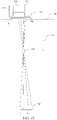
- FIGURE 3 is a schematic diagram illustrating in side view a directional display device. Further, FIGURE 3 illustrates additional detail of a side view of the operation of a stepped waveguide 1, which may be a transparent material.
- the stepped waveguide 1 may include an illuminator input end 2, a reflective end 4, a first guide surface 6 which may be substantially planar, and a second guide surface 8 which includes intermediate regions 10 and light extraction features 12.
- light rays 16 from an illuminator element 15c of an illuminator array 15 may be guided in the stepped waveguide 1 by means of total internal reflection by the first guide surface 6 and total internal reflection by the intermediate regions 10 of the second guide surface 8, to the reflective end 4, which may be a mirrored surface.
- reflective end 4 may be a mirrored surface and may reflect light, it may in some embodiments also be possible for light to pass through reflective end 4.
- light ray 18 reflected by the reflective end 4 may be further guided in the stepped waveguide 1 by total internal reflection at the reflective end 4 and may be reflected by extraction features 12.
- Light rays 18 that are incident on extraction features 12 may be substantially deflected away from guiding modes of the stepped waveguide 1 and may be directed, as shown by ray 20, through the first guide surface 6 to an optical pupil that may form a viewing window 26 of an autostereoscopic display.
- the width of the viewing window 26 may be determined by at least the size of the illuminator, number of illuminator elements 15n illuminated, output design distance and optical power in the reflective end 4 and extraction features 12.
- each viewing window 26 represents a range of separate output directions with respect to the surface normal direction of the spatial light modulator 48 that intersect with a window plane 106 at the nominal viewing distance.
- FIGURE 4A is a schematic diagram illustrating in front view a directional display device which may be illuminated by a first illuminator element and including curved light extraction features. Further, FIGURE 4A shows in front view further guiding of light rays from illuminator element 15c of illuminator array 15, in the stepped waveguide 1 having an optical axis 28.
- the directional backlight may include the stepped waveguide 1 and the light source illuminator array 15. Each of the output rays are directed from the input end 2 towards the same optical window 260 from the respective illuminator 15c. The light rays of FIGURE 4A may exit the reflective end 4 of the stepped waveguide 1.
- ray 16 may be directed from the illuminator element 15c towards the reflective end 4.
- Ray 18 may then reflect from a light extraction feature 12 and exit the reflective end 4 towards the optical window 260.
- light ray 30 may intersect the ray 20 in the optical window 260, or may have a different height in the viewing window as shown by ray 32.
- sides 22, 24 of the waveguide 1 may be transparent, mirrored, or blackened surfaces.
- light extraction features 12 may be elongate, and the orientation of light extraction features 12 in a first region 34 of the second guide surface 8 (shown in FIGURE 3 , but not shown in FIGURE 4A ) may be different to the orientation of light extraction features 12 in a second region 36 of the second guide surface 8. Similar to other embodiments discussed herein, for example as illustrated in FIGURE 3 , the light extraction features of FIGURE 4A may alternate with the intermediate regions 10.
- the stepped waveguide 1 may include a reflective surface on reflective end 4. In one embodiment, the reflective end of the stepped waveguide 1 may have positive optical power in a lateral direction across the stepped waveguide 1.
- the light extraction features 12 of each directional backlight may have positive optical power in a lateral direction across the waveguide.
- each directional backlight may include light extraction features 12 which may be facets of the second guide surface.
- the second guide surface may have regions alternating with the facets that may be arranged to direct light through the waveguide without substantially extracting it.
- FIGURE 4B is a schematic diagram illustrating in front view a directional display device which may illuminated by a second illuminator element. Further, FIGURE 4B shows the light rays 40, 42 from a second illuminator element 15h of the illuminator array 15. The curvature of the reflective surface on the reflective end 4 and the light extraction features 12 cooperatively produce a second optical window 440 laterally separated from the optical window 260 with light rays from the illuminator element 15h.
- the arrangement illustrated in FIGURE 4B may provide a real image of the illuminator element 15c at an optical window 260 in which the real image may be formed by cooperation of optical power in reflective end 4 and optical power which may arise from different orientations of elongate light extraction features 12 between regions 34 and 36, as shown in FIGURE 4A .
- the arrangement of FIGURE 4B may achieve improved aberrations of the imaging of illuminator element 15c to lateral positions in optical window 260. Improved aberrations may achieve an extended viewing freedom for an autostereoscopic display while achieving low cross talk levels.
- FIGURE 5 is a schematic diagram illustrating in front view an embodiment of a directional display device having substantially linear light extraction features. Further, FIGURE 5 shows a similar arrangement of components to FIGURE 1 (with corresponding elements being similar), with one of the differences being that the light extraction features 12 are substantially linear and parallel to each other. Advantageously, such an arrangement may provide substantially uniform illumination across a display surface and may be more convenient to manufacture than the curved extraction features of FIGURE 4A and FIGURE 4B .
- the optical axis 321 of the directional waveguide 1 may be the optical axis direction of the surface at the reflective end 4.
- the optical power of the reflective end 4 is arranged to be across the optical axis direction, thus rays incident on the reflective end 4 will have an angular deflection that varies according to the lateral offset 319 of the incident ray from the optical axis 321.
- FIGURE 6A is a schematic diagram illustrating one embodiment of the generation of a first viewing window in a time multiplexed imaging directional display device in a first time slot
- FIGURE 6B is a schematic diagram illustrating another embodiment of the generation of a second viewing window in a time multiplexed imaging directional backlight apparatus in a second time slot
- FIGURE 6C is a schematic diagram illustrating another embodiment of the generation of a first and a second viewing window in a time multiplexed imaging directional display device.
- FIGURE 6A shows schematically the generation of viewing window 26 from stepped waveguide 1.
- Illuminator element group 31 in illuminator array 15 may provide a light cone 17 directed towards a viewing window 26 (that may comprise a single optical window 260 or an array of optical windows 260).
- FIGURE 6B shows schematically the generation of viewing window 44.
- Illuminator element group 33 in illuminator array 15 may provide a light cone 19 directed towards viewing window 44 (that may comprise a single optical window 440 or an array of optical windows 440).
- viewing windows 26 and 44 may be provided in sequence as shown in FIGURE 6C .
- illuminator element groups 31, 33 each include one or more illumination elements from illumination elements 15a to 15n, where n is an integer greater than one.
- FIGURE 7 is a schematic diagram illustrating one embodiment of an observer tracking autostereoscopic display apparatus including a time multiplexed directional display device.
- selectively turning on and off illuminator elements 15a to 15n along axis 29 provides for directional control of viewing windows 26, 44.
- the head 45 position may be monitored with a camera, motion sensor, motion detector, or any other appropriate optical, mechanical or electrical means, and the appropriate illuminator elements of illuminator array 15 may be turned on and off to provide substantially independent images to each eye irrespective of the head 45 position.
- the head tracking system may provide monitoring of more than one head 45, 47 (head 47 not shown in FIGURE 7 ) and may supply the same left and right eye images to each viewers' left and right eyes providing 3D to all viewers. Again similar operation can be achieved with all the imaging directional backlights described herein.
- FIGURE 8 is a schematic diagram illustrating one embodiment of a multi-viewer directional display device as an example including an imaging directional backlight.
- at least two 2D images may be directed towards a pair of viewers 45, 47 so that each viewer may watch a different image on the spatial light modulator 48.
- the two 2D images of FIGURE 8 may be generated in a similar manner as described with respect to FIGURE 7 in that the two images would be displayed in sequence and in synchronization with sources whose light is directed toward the two viewers.
- One image is presented on the spatial light modulator 48 in a first phase
- a second image is presented on the spatial light modulator 48 in a second phase different from the first phase.
- the output illumination is adjusted to provide first and second viewing windows 26, 44 respectively. An observer with both eyes in viewing window 26 will perceive a first image while an observer with both eyes in viewing window 44 will perceive a second image.
- FIGURE 9 is a schematic diagram illustrating a privacy directional display device which includes an imaging directional backlight.
- 2D display systems may also utilize directional backlighting for security and efficiency purposes in which light may be primarily directed at the eyes of a first viewer 45 as shown in FIGURE 9 .
- first viewer 45 may be able to view an image on device 50
- light is not directed towards second viewer 47.
- second viewer 47 is prevented from viewing an image on device 50.
- Each of the embodiments of the present disclosure may advantageously provide autostereoscopic, dual image or privacy display functions.
- FIGURE 10 is a schematic diagram illustrating in side view the structure of a time multiplexed directional display device as an example including an imaging directional backlight. Further, FIGURE 10 shows in side view an autostereoscopic directional display device, which may include the stepped waveguide 1 and a Fresnel lens 62 arranged to provide the viewing window 26 for a substantially collimated output across the stepped waveguide 1 output surface.
- a vertical diffuser 68 may be arranged to extend the height of the viewing window 26 further and to achieve blurring in directions in the vertical direction (parallel to the x-axis) while minimizing blurring in directions in the lateral direction (y axis). The light may then be imaged through the spatial light modulator 48.
- the illuminator array 15 may include light emitting diodes (LEDs) that may, for example, be phosphor converted blue LEDs, or may be separate RGB LEDs.
- the illuminator elements in illuminator array 15 may include a uniform light source and spatial light modulator arranged to provide separate illumination regions.
- the illuminator elements may include laser light source(s).
- the laser output may be directed onto a diffuser by means of scanning, for example, using a galvo or MEMS scanner.
- laser light may thus be used to provide the appropriate illuminator elements in illuminator array 15 to provide a substantially uniform light source with the appropriate output angle, and further to provide reduction in speckle.
- the illuminator array 15 may be an array of laser light emitting elements.
- the diffuser may be a wavelength converting phosphor, so that illumination may be at a different wavelength to the visible output light.
- FIGURES 1 to 10 variously describe: a waveguide 1; a directional backlight comprising such a waveguide 1 and an illuminator array 15; and a directional display device including such a directional backlight and an SLM 48.
- a waveguide 1 a directional backlight comprising such a waveguide 1 and an illuminator array 15
- a directional display device including such a directional backlight and an SLM 48.
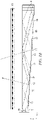
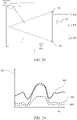
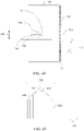
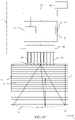
- FIGURE 11 is a schematic diagram illustrating a front view of another imaging directional backlight, as illustrated, a wedge type directional backlight
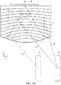
- FIGURE 12 is a schematic diagram illustrating a side view of a similar wedge type directional display device.
- a wedge type directional backlight is generally discussed by U.S. Patent No. 7,660,047 and entitled “Flat Panel Lens,” which is herein incorporated by reference in its entirety.
- the structure may include a wedge type waveguide 1104 with a bottom surface which may be preferentially coated with a reflecting layer 1106 and with an end corrugated surface 1102, which may also be preferentially coated with a reflecting layer 1106.
- a directional display device may include a waveguide having an input end, first and second opposed guide surfaces for guiding light along the waveguide, and a reflective end facing the input end for reflecting light from the input light back through the waveguide.
- the directional display device may also include an array of light sources disposed at different input positions across the input end of the waveguide.
- the waveguide may be arranged to direct input light from the light sources as output light through the first guide surface after reflection from the reflective end into optical windows in output directions relative to the normal to the first guide surface and may be primarily dependent on the input positions.
- the directional display device may also include a transmissive spatial light modulator arranged to receive the output light from the first guide surface and arranged to modulate a first polarization component of the output light having a first polarization.
- the first guide surface may be arranged to guide light by total internal reflection and the second guide surface may be substantially planar and inclined at an angle to reflect light in directions that break the total internal reflection for outputting light through the first guide surface.
- the wedge type directional backlight may be part of a directional display device.
- the directional display device may also include a deflection element extending across the first guide surface of the waveguide for deflecting light towards the normal to the spatial light modulator.
- light may enter the wedge type waveguide 1104 from local sources 1101 and the light may propagate in a first direction before reflecting off the end surface.
- Light may exit the wedge type waveguide 1104 while on its return path and may illuminate a display panel 1110.
- a wedge type waveguide provides extraction by a taper that reduces the incidence angle of propagating light so that when the light is incident at the critical angle on an output surface, it may escape. Escaping light at the critical angle in the wedge type waveguide propagates substantially parallel to the surface until deflected by a redirection layer 1108 such as a prism array. Errors or dust on the wedge type waveguide output surface may change the critical angle, creating stray light and uniformity errors.
- an imaging directional backlight that uses a mirror to fold the beam path in the wedge type directional backlight may employ a faceted mirror that biases the light cone directions in the wedge type waveguide.
- Such faceted mirrors are generally complex to fabricate and may result in illumination uniformity errors as well as stray light.
- the wedge type directional backlight and optical valve further process light beams in different ways.
- light input at an appropriate angle will output at a defined position on a major surface, but light rays will exit at substantially the same angle and substantially parallel to the major surface.
- light input to a stepped waveguide of an optical valve at a certain angle may output from points across the first side, with output angle determined by input angle.
- the stepped waveguide of the optical valve may not require further light re-direction films to extract light towards an observer and angular non-uniformities of input may not provide non-uniformities across the display surface.
- a wedge type waveguide such as wedge type waveguide 1104 may be used in a directional backlight, and may replace the stepped waveguide 1 in the various structures shown in FIGURES 1 to 10 described above and in the structures described below.
- the directional display device includes a directional backlight including a waveguide and an SLM.
- the waveguides, directional backlights and directional display devices are based on and incorporate the structures of FIGURES 1 to 10 above, but could equally be adapted to replace the stepped waveguide 1 by a wedge type waveguide as described above. Except for the modifications and/or additional features which will now be described, the above description applies equally to the following waveguides, directional backlights and display devices, but for brevity will not be repeated.
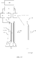
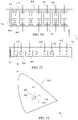
- FIGURE 13 is a schematic diagram illustrating a directional display apparatus including a display device 100 and a control system. The arrangement and operation of the control system will now be described and may be applied, with changes as necessary, to each of the display devices disclosed herein.
- the directional display device 100 includes a directional backlight that includes waveguide 1 and an array 15 of illuminator elements 15n arranged as described above.
- the control system is arranged to selectively operate the illumination elements 15a-15n to direct light into selectable optical windows.
- the waveguide 1 is arranged as described above.
- the reflective end 4 converges the reflected light.
- a Fresnel lens 62 may be arranged to cooperate with reflective end 4 to achieve viewing windows 26 at a window plane 106 observed by an observer 99.
- a transmissive spatial light modulator (SLM) 48 may be arranged to receive the light from the directional backlight. Further a diffuser 68 may be provided to substantially remove Moiré beating between the waveguide 1 and pixels of the SLM 48 as well as the Fresnel lens 62.
- SLM spatial light modulator
- the control system may include a sensor system arranged to detect the position of the observer 99 relative to the display device 100.
- the sensor system includes a position sensor 70, such as a camera, and a head position measurement system 72 that may for example include a computer vision image processing system.
- the control system may further include an illumination controller 74 and an image controller 76 that are both supplied with the detected position of the observer supplied from the head position measurement system 72.
- the illumination controller 74 supplies drive signals to the illuminator elements 15n. By controlling the drive signals, the illumination controller 74 selectively operates the illuminator elements 15n to direct light to into the viewing windows 26 in cooperation with waveguide 1.
- the illumination controller 74 selects the illuminator elements 15n to be operated in dependence on the position of the observer detected by the head position measurement system 72, so that the viewing windows 26 into which light is directed are in positions corresponding to the left and right eyes of the observer 99. In this manner, the lateral output directionality of the waveguide 1 corresponds with the observer position.
- the illumination controller 74 may be arranged to vary the drive signals supplied to respective illuminator element 15to control the luminous flux of the light emitted by the respective light sources of the array 15, which may be referred to as the grey level of light.
- the luminous flux of a light source is a measure of the optical power emitted by the light source, measured in lumens.
- Control of the luminous flux may be effected by any suitable drive scheme including, without limitation, voltage modulation, current modulation, pulse width modulation, control of a spatial light modulator arranged between a light source and the input end 2, or other known greyscale drive scheme.
- the luminous flux emitted by each illuminator element 15n may be varied by altering the current flowing in each addressable device, or by a pulse width modulation scheme where the length of one or more pulses is changed in order to vary the brightness perceived by the observer due to the persistence of vision. It is also possible to combine these two effects to achieve the brightness control desired.
- the image controller 76 controls the SLM 48 to display images.
- the image controller 76 and the illumination controller 74 may operate as follows.
- the image controller 76 controls the SLM 48 to display temporally multiplexed left and right eye images.
- the illumination controller 74 operate the light sources 15 to direct light into viewing windows in positions corresponding to the left and right eyes of an observer synchronously with the display of left and right eye images. The position of the viewing windows may primarily depend on the detected position of the observer. In this manner, an auto stereoscopic effect is achieved using a time division multiplexing technique.
- a luminous flux controller 580 operating under user or automatic control, may control the illumination controller 74 to implement a method of controlling the illuminator elements 15n of the directional backlight to output light with luminous fluxes, scaled inversely by the width associated with the respective illuminator elements 15n in the lateral direction, that varies across the array of illuminator elements 15.
- the quantity of luminous flux that is varied across the array 15 is the luminous flux of an individual illuminator 15 that is scaled.
- the scaling is inverse with the width associated with the respective illuminator elements 15n in the lateral direction.
- the purpose of that scaling is to take account of any variation in the pitch of the illuminator elements 15n across the array 15.
- the scaled luminous fluxes are simply the actual luminous fluxes of the illuminator elements 15n, because the scaling is constant.
- the pitch of the illuminator elements 15n in the lateral direction is variable, then the scaled luminous fluxes take into account that varying pitch.
- the scaled luminous fluxes may therefore take into account gaps between the light sources and non-uniformities across luminous flux of the respective outputs.
- the width associated with an illuminator element 15n may be taken as the pitch of the array illuminator elements 15n at the illuminator element 15n being considered.
- the width associated with an illuminator element 15n may be taken as the width between the mid-points of the gaps between the illuminator elements 15n.
- the scaled luminous flux is described further in reference to FIGURE 53 .
- the scaled luminous fluxes are considered, because in the display device 100 this quantity affects the luminous intensity of the output light as described further below.
- the luminous intensity of the display device is a measure of the power emitted by the display device in a particular direction per unit solid angle. Therefore the scaled luminous fluxes are controlled to provide a desired luminous intensity.
- the brightness of the display device 100 as perceived by the observer 99 is elicited by the luminance which is a photometric measure of the luminous intensity per unit area of light traveling in a given direction.
- variation of the luminous flux linear density allows the perceived brightness to be controlled, for example allowing the perceived brightness (luminance) to be varied for different positions of the observer 99 and/or power consumption to be minimized for a given perceived brightness.
- the luminous flux under consideration is the total luminous flux emitted. This may be derived by integrating the luminous flux emitted by the illuminator elements 15n over the direction perpendicular to the lateral direction.
- the luminous flux controller 580 may control the luminous flux to vary across the array of illuminator elements 15n in a luminous flux distribution that is fixed with respect the position in the lateral direction.
- the luminous flux controller 580 may control the luminous flux to vary across the array of illuminator elements 15n in dependence on the detected position of the observer 99, as detected by the sensor system.
- the luminous flux controller 580 may control the luminous flux to vary across the array of illuminator elements 15n.
- the luminous flux controller 580 controls the scaled luminous fluxes to vary across the array of illuminator elements 15n in a luminous flux distribution that is fixed with respect the position in the lateral direction.
- This has particular advantage when the display device 100 is operated to display a 2D image viewable from a wide angle compared to a directional mode of operation such as an autostereoscopic mode. In that case, all the illuminator elements 15n may simultaneously be operated, in which case the sensor system might be unused or omitted.
- the illumination controller 74 may operate the light sources 15 to direct light into a single viewing window visible by both eyes in dependence on the detected position of the observer with the SLM 48 arranged to operate in a single phase for 2D viewing for privacy and high efficiency modes of operation. Such a viewing window is sufficiently wide to be seen by both the left and right eyes of an observer.
- the fixed luminous flux distribution may also be applied when the display device is operated to provide an autostereoscopic 3D display.
- FIGURE 14A is a schematic diagram illustrating a top view of a directional backlight that includes waveguide 1 and an array of illuminator elements 15n that provide an array of optical windows 260 in a window plane 106, the output direction and hence nominal lateral position in the window plane of each optical window 260 being dependant on the lateral position of the respective illuminator in the array 15..
- the luminous intensity of the display seen from the optical windows 260 may vary with position of an observer 99 (with right and left eye positions 560, 562 as indicated).
- each element of the array 15 of illuminator elements 15n and each optical window 260 of the array of optical windows will comprise the effects of scatter, diffusion, diffraction and imaging properties of the optical components arranged between the array 15 and window plane 106.
- the optical windows 260 are not perfect images of the illuminator elements 15n.
- the lateral position 262 of the optical windows 260 will typically be directly related to the lateral position 261 of the illuminator elements 15n in the array 15.
- the luminous flux controller 580 may control the scaled luminous fluxes to vary across the array of illuminator elements 15n in a luminous flux distribution with the input position of the illuminator element 15 in the lateral direction, that produces a desired luminance intensity distribution that represents the variation of the luminous intensity of the output light with the angle of the output directions, examples of which will now be described.
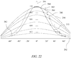
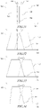
- FIGURE 14B is a schematic diagram illustrating a graph of the luminous intensity 264 of the output light against viewing position 262 in the window plane 106 corresponding to the angle ⁇ of the output directions.
- Luminous intensity distribution 266 is Lambertian, having a luminous intensity that varies as the cosine of viewing angle ⁇ and so the luminous intensity across the display may vary, while the observed luminance of the display is constant from viewing positions 500 to 502 within the viewing windows.
- a Lambertian emitter achieves the same apparent luminance of a surface independent of the observer's angle of view.
- the surface has an isotropic luminance (measured in candela per metre 2 , or lumen per steradian per metre 2 ) and the variation of luminous intensity (measured in candela, or lumen per steradian) 264 obeys Lambert's cosine law wherein luminous intensity observed from an ideal diffuse radiator is directly proportional to the cosine of the angle ⁇ between the observer's line of sight and the surface normal.
- Lambertian is used to describe the emission of a display over a defined angular range, for example the total width of optical windows of the display. Thus at positions in the window plane outside the width of the optical windows, the luminous intensity distribution may behave in a non-Lambertian manner.
- the luminous intensity may typically be considered for a point on the backlight, for example the point corresponding to the centre of the SLM 48.
- the luminance (luminous intensity per unit area) of the display system may vary across the display area due to non-uniformities of output and will further vary with subtended viewing angle of the respective unit area.
- FIGURE 14B further shows a luminous intensity distribution for a luminous intensity distribution 272 having a gain greater than one.
- the luminous intensity distribution 272 has a maximum luminous intensity, corresponding to the global maximum of the luminous flux distribution, that is greater than the luminous intensity distribution 266 that is Lambertian, wherein the total power of the two luminous intensity distributions 266 and 272 is the same over all output directions 500 to 502.
- the peak luminous intensity is greater for on-axis positions, and falls at a faster rate than the luminous intensity distribution 266 that is Lambertian.
- the display luminance falls for off-axis viewing positions.
- the ratio of luminance of distribution 272 to peak luminance of distribution 266 is often referred to as the gain of a display system.
- the luminous flux controller 580 may control the scaled luminous fluxes to vary across the array of illuminator elements 15n in a luminous flux distribution that provides the output light with a luminous intensity distribution 266 that is Lambertian or with a luminous intensity distribution 272 having a gain greater than one, as follows.
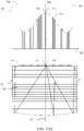
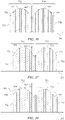
- FIGURE 15A is a schematic diagram illustrating a graph of luminous intensity of the output light against viewing position 262 in the window plane 106 corresponding to the lateral angle ⁇ of the output direction with respect to the optical axis 238, as well as a method to adjust the scaled luminous fluxes of array 15.
- the luminous intensity distributions 266 and 272 are shown but with their peak luminous intensities matched so that the on-axis luminances are matched and the display appears equally bright for on-axis viewing positions.
- the luminous intensity distribution 266 that is Lambertian may be achieved by controlling all of the illuminator elements of array 15 to have substantially the same scaled luminous flux output.
- the luminous intensity for off-axis positions may be reduced in comparison to the distribution 266, as indicated by arrows 270. This may be achieved by controlling the scaled luminous fluxes of the illuminator elements to vary across the array 15 in luminous flux distribution as follows.
- FIGURE 15B is a schematic diagram illustrating a graph of luminous flux distribution for an array of illuminator elements and method to adjust the scaled luminous fluxes of the array 15.
- the scaled luminous fluxes 263 may be plotted against the lateral position 261 in the lateral direction across the input end 2 of the waveguide 1.
- the scaled luminous fluxes 263 has a constant luminous flux distribution 269 to provide the luminous intensity distribution 266 that is Lambertian.
- Arrows 271 shows the drop in scaled luminous flux, compared to constant luminous flux distribution 269, for respective light sources corresponding to arrow 270 at respective optical window position 262, to reach a non-linear luminous flux distribution 273 that provides the luminous intensity distribution 272 having a gain greater than one.
- the luminous flux distribution 273 has a global maximum 508 of luminous flux and reduces on either side of the global maximum 508.
- the global maximum 508 occurs in respect of the illuminator elements aligned with the optical axis of the waveguide1.
- illuminator elements of the array 15 may be controlled so that their scaled luminous fluxes vary in accordance with the non-linear luminous flux distribution 273, thereby providing the display device 100 with the luminous intensity distribution 272 having a gain greater than one. That is, the luminous intensity 264 of the output light varies with the angle 262 of the output directions in an actual luminous intensity distribution 272 that is greater than a notional luminous intensity distribution 266 that is Lambertian and has the same total luminous intensity over all output directions as the actual luminous intensity distribution 272.
- FIGURE 15C is a schematic diagram illustrating a detail of FIGURE 15B , but with the y-axis plotting the actual luminous flux 265 integrated over the direction perpendicular to the lateral direction.
- the actual luminous flux 265 at a given lateral position 261 across the input end 2 is the integral of light captured by the waveguide in a slice perpendicular to the lateral direction, i.e. parallel to the z-axis.
- the actual luminous flux 265 is the same as the integrated flux output of a slice of the light source in the z-axis.
- the light sources of the array 15 will typically have substantially non-uniform distribution of actual luminous flux 265 in the lateral direction (y-axis)due to gaps between light sources and structure within the light sources.
- the light source may comprise an LED with blue and yellow light emitting regions. Different actual luminous flux 265 and chromaticity outputs in the lateral direction when integrated across the thickness of the input end 2 may thus be achieved.
- the light sources may be arranged in a stepwise manner so that light source number 504 is related to a given luminous flux 506 providing the scaled luminous fluxes with the luminous flux distribution 273.
- luminous flux distribution 273 may be provided by the actual luminous flux 265 averaged over the width in the lateral direction associated with a single illuminator element 15n.
- the illuminator elements 15n are not imaged precisely in the window plane 106 so that the viewing windows may include laterally diffused overlapping optical windows.
- the transformation from luminous flux distribution 273 to luminous intensity distribution 272 may further take into account blurring between adjacent optical windows 260 within the viewing windows 26, and may be arranged to achieve the desired luminous intensity distribution 262.
- the output luminance of the display may be maintained for on-axis viewing positions, and reduced for off-axis viewing positions.
- the power consumption of the display may be reduced for less advantageous viewing positions, improving display efficiency, battery charge lifetime and reducing display cost.
- FIGURE 15D is a schematic diagram illustrating a graph of luminous flux distribution and a front view of a directional backlight aligned with the luminous flux distribution.
- luminous flux distribution 273 of the scaled luminous fluxes 263 with lateral position 261 is shown aligned with respective illuminator elements of array 15.
- illuminator elements 514, 516 have respective scaled luminous fluxes 510, 512, including the global maximum 508 of distribution 273 that is aligned with the optical axis 232 of the waveguide 1.
- the distribution 273 is provided between positions 261 of 501, 503.
- the global maximum of the flux distribution may be in respect of the illuminator elements aligned with the optical axis 232 of the waveguide.
- the global maximum of the flux distribution may be in respect of the illuminator elements 514, 516 aligned with the optical axis 232 of the waveguide 1.
- the peak luminous intensity of output is provided on-axis with respect to the display normal 107 that may be aligned with the optical axis 232.
- the luminance is greatest for the on-axis position for displays with gains greater than one.
- the on-axis position is typically the desirable viewing position, particularly for mobile displays and so the display will look brightest for the optimum viewing conditions while achieving reduced power consumption for off-axis viewing positions.
- the global maximum 508 of the luminous flux distribution may be in respect of the illuminator elements 514, 516 aligned with the optical axis 232 of the waveguide 1. Such an arrangement may achieve a global maximum 259 of luminous intensity 264, which may be for respective optical windows that are aligned with the optical axis 232 of the waveguide 1.
- FIGURE 15D illustrates one arrangement of illuminator elements for wide angle 2D viewing; that is the illuminator elements may operate continuously or in a single phase and the spatial light modulator 48 may include a single 2D image. As all the illuminator elements 15n may simultaneously be operated, the sensor system might be unused or omitted. It would be further desirable to provide the power saving advantages of increased display gain in auto stereoscopic mode for off-axis viewing positions.
- FIGURES 15E to 15F are schematic diagrams illustrating a graph of luminous flux distribution for an auto stereoscopic Lambertian display system.
- the scaled luminous fluxes vary across the array of illuminator elements 15n in a luminous flux distribution that is fixed with respect the position in the lateral direction, but the display device is operated to provide an autostereoscopic 3D display as described above by means of the SLM 48 displaying temporally multiplexed left and right eye images and light being directed into viewing windows in positions corresponding to the left and right eyes of an observer synchronously with the display of left and right eye images.
- FIGURES 15E illustrates an example in which a constant luminous flux distribution 269 is used to provide a luminous intensity distribution 266 that is Lambertian as shown in FIGURE 14B .
- Viewing windows 26 may be formed from illumination of illuminator elements in a sub-array 520 for a left eye phase and a sub-array 522 in a right eye phase.
- the scaled luminous fluxes may have a constant value and the display may maintain a Lambertian appearance with viewing angle.
- the number of illuminator elements illuminated is much reduced compared to the arrangement of FIGURE 15D .
- the luminance for each eye will be substantially constant, reducing the appearance of depth errors in autostereoscopic viewing and increasing viewer comfort.
- FIGURE 15F and 15G illustrate an example in which a non-linear luminous flux distribution 273 is used to provide a luminous intensity distribution 272 having a gain greater than one.
- the illuminator elements may be controlled to output light with scaled luminous fluxes 263 that vary across the illuminator elements in dependence on the detected position of the observer 99.
- FIGURE 15F illustrates the case that the detected position of the observer is aligned with the optical axis
- FIGURE 15F illustrates the case that the detected position of the observer is offset.
- Sub-arrays 520, 522 of illuminator elements for the left and right eyes are selectively operated, changing with the detected position of the observer.
- the sub-arrays 520, 522 of illuminator elements have varying luminous intensity across their width to achieve the gain.
- the illuminator elements may be controlled to output light with scaled luminous fluxes 263 that vary across the illuminator elements in dependence on the detected position of the observer 99 in a manner that produces a luminous intensity 264 of the output light that varies with the angle 262 of the output light in the luminous intensity distribution 272 having a gain greater than one.
- the power consumption of the array 15 of illuminator elements is reduced compared to the arrangement of FIGURE 15E , since not all the illuminator elements are operated at any one time.
- Advantageously off-axis power consumption may be reduced compared to on-axis positions, reducing power consumption further.
- FIGURE 15H is a schematic diagram illustrating a further graph of luminous flux distribution for an autostereoscopic display system with a gain of greater than one and an off-axis viewing position.
- the arrays 520, 522 of illuminator elements are arranged to track the distribution 273 shown by matching the scaled luminous fluxes at position 524, but have equal luminous flux linear density across the sub-arrays 520 and 522.
- the scaled luminous fluxes vary across the array of illuminator elements 15n in a luminous flux distribution that is not fixed with respect the position in the lateral direction the illuminator elements but is varies in dependence on the detected position of the observer. In particular, this is controlled in a manner that produces a luminous intensity 264 of the output light that varies with the angle 262 of the detected position of the observer in the luminous intensity distribution 272 having a gain greater than one.
- the left and right eye viewing windows may be arranged with luminous intensity 264 distributions to achieve substantially equal luminance for each eye in the manner of Lambertian distribution of luminous intensity.
- the power consumption of the array 15 of illuminator elements is reduced compared to the arrangement of FIGURE 15E , since not all the illuminator elements are operated at any one time.
- Off-axis power consumption may be reduced compared to on-axis positions and each eye may perceive an image luminance that is substantially equally, reducing depth errors in auto stereoscopic viewing and increasing viewer comfort.
- FIGURE 16 is a schematic diagram illustrating an illuminator element addressing apparatus.
- illumination controller 74 may be arranged to address illuminator elements 243 of array 15 by means of drive lines 244 to provide drive signals to the array of illuminator elements.
- illuminator elements 243 may have varying scaled luminous fluxes, as described elsewhere.
- scaled luminous flux variations may be achieved by means of controlling current into the respective sources 243 by the illumination controller 74 and control system.
- Control of luminous flux distribution may be achieved by means of current control or voltage control for example. Further the variation may be adjusted according to user requirements, thus a user may select a high gain, low power consumption mode or may select a wide field of view mode.
- the array 15 of illuminator elements may be arranged at the input end 2 of a waveguide 1, for example as shown in FIGURE 13 or may be at the input end 1103 of a wedge waveguide 1104 as shown in FIGURE 12 .
- FIGURE 17 is a schematic diagram illustrating a graph of luminous intensity for an array of optical windows and respective optical windows, in a further example in which the display device is operated to provide an auto stereoscopic 3D display as described above, and the scaled luminous fluxes vary across the array of illuminator elements 15n in dependence on the detected position of the observer.
- illuminator elements of array 15 may provide a constant scaled luminous fluxes and an optical system in such conditions may achieve a Lambertian profile of luminous intensity at the window plane.
- Each source of array 15 may provide an optical window 249 in the window plane 106.
- a left eye viewing window 247 is provided by an array 530 of left eye optical windows and a right eye viewing widow 251 is provided by an array 532 of right eye optical windows, in left and right eye illumination phases respectively.
- the left and right eye viewing windows 247 and 251 are generated in dependence on the detected position of the observer.
- the scaled luminous fluxes vary across the array of illuminator elements 15n in accordance with a luminous flux distribution that produces a luminous intensity of the output light in the optical windows that varies with the angle of the output directions in a luminous intensity distribution 267.
- luminous intensity distributions 266, 267 may be Lambertian.
- similar formation of viewing windows from optical windows are provided.
- Different luminous intensity distributions for viewing windows 26 other than Lambertian are further provided by combining arrays of optical windows 249.
- FIGURE 18 is a schematic diagram illustrating a graph of optical window luminous intensity 264 against viewing position 262 for a waveguide 1 including uniform luminous intensity of illuminator elements in array 15, in an alternative construction of the waveguide 1.
- a substantially Lambertian luminous intensity distribution 266 is achieved.
- non-Lambertian behaviour may be exhibited by the waveguide 1 as will be described with reference to FIGUREs 19A-19B .
- a luminous intensity distribution 268 may be achieved by the waveguide 1 including horn shaped features 540, 542.
- the off-axis luminous intensity is substantially higher than that provided by a Lambertian output luminous emittance distribution 266; in other words the luminance of the display may increase for some off-axis viewing positions. It would be desirable to reduce power consumption of the array 15 of illuminator elements when operating in 2D mode by means of compensation of the distribution 268.
- FIGURE 19A is a schematic diagram illustrating a perspective view of a light ray incident with a first direction onto a light extraction feature of a waveguide 1 of an alternative construction in which the light extraction feature 12 are not mirrored and instead reflect light by TIR.
- Surface 8 of the waveguide 1 may include intermediate regions 10 and light extraction features 12, which may be referred to herein as light extraction facets.
- light rays 300 at an angle 307 to the normal 304 to feature 12 and that are parallel to features 10 are reflected by total internal reflection at feature 12 along ray 302.
- light rays 301 that remain in the same x-z plane as rays 300 that at a smaller angle 307 to the surface normal 304 of features 12 may be transmitted to ray 305.
- rays 305 may be lost to the output luminous intensity distribution.
- FIGURE 19B is a schematic diagram illustrating a perspective view of a light ray incident with a second direction onto a light extraction feature of a waveguide 1 of the same construction as FIGURE 19A .
- Off-axis rays 308 may be provided by an off-axis illuminator element of array 15 and are incident at an angle 308 to on-axis rays in the x-y plane.
- Rays 309 that for on axis incidence that would be transmitted by the feature 12 are incident at an angle 312 to the normal 304 that has a greater resolved angle than angle 307 and thus undergoes total internal reflection at the feature 12.
- light rays 311 are reflected rather than transmitted.
- the control system is arranged to control the illuminator elements to output light with scaled luminous fluxes that vary across the array of illuminator elements in manner that compensates for this variation in the luminous flux of the output light reflected by the facets, as follows.
- FIGURE 20A is a schematic diagram illustrating a graph of optical window luminous intensity against viewing position in the window plane of a waveguide and a method to adjust scaled luminous fluxes of the illuminator elements 15n.
- the luminous intensity distribution may be modified as shown by arrows 270. This may be achieved by controlling the scaled luminous fluxes of the illuminator elements 15n to vary across the array 15 in luminous flux distribution as follows.
- FIGURE 20B is a schematic diagram illustrating a graph of luminous flux distribution for an array of illuminator elements and method to adjust the scaled luminous fluxes of the illuminator elements 15n for a waveguide 1.
- Arrows 271 shows the drop in the scaled luminous fluxes, compared to constant luminous flux distribution 269, for respective light sources corresponding to arrow 270 at respective optical window position 262, to reach a non-linear luminous flux distribution 277 that provides the luminous intensity distribution 266 that is Lambertian.
- arrows 271 that may have a length proportionately equivalent to the length of arrows 270 for a respective equivalent positions 262, 261, and the luminous flux distribution 277 may be provided.
- the luminous flux distribution 277 has a global maximum 508 of luminous flux and reduces on either side of the global maximum 508 is provided across the array 15.
- the global maximum 508 occurs in respect of the illuminator elements aligned with the optical axis of the waveguide 1.
- the luminous flux distribution 277 also has 'anti-horn' features 544, 546 to compensate for horn features in the distribution 268.
- the illuminator elements of the array 15 corresponding to optical windows that are not seen by the observer 99 may be extinguished, advantageously reducing power consumption
- the illuminator elements may be controlled to output light with scaled luminous fluxes 263 that vary across the illuminator elements in dependence on the detected position of the observer 99 in a manner that produces a luminous intensity 264 of the output light that varies with the angle 262 of the detected position of the observer 99 in a luminous intensity distribution 266 that is Lambertian.
- the non-Lambertian luminous intensity output of the waveguide 1 can be compensated for, achieving substantially uniform luminance across the viewing angle of the display.
- FIGURE 21A is a schematic diagram illustrating a graph of optical window luminous intensity against viewing position in the window plane of a waveguide and a method to adjust the scaled luminous fluxes of the illuminator elements 15n.
- the luminous intensity distribution 268 can be adjusted to achieve luminance intensity distribution 272 having a gain greater than one.
- the luminous intensity distribution may be modified as shown by arrows 270. This may be achieved by controlling the scaled luminous flux of the illuminator elements to vary across the array 15 in luminous flux distribution as follows.
- FIGURE 21B is a schematic diagram illustrating a graph of luminous flux distribution for an array of illuminator elements and method to adjust the scaled luminous fluxes of the of the illuminator elements 15n for a waveguide 1.
- the luminous flux distribution 275 may be achieved in a similar manner to that described for FIGURE 20B .
- Arrows 271 shows the drop in scaled luminous flux, compared to constant luminous flux distribution 269, for respective light sources corresponding to arrow 270 at respective optical window position 262, to reach a non-linear luminous flux distribution 275 that provides the luminous intensity distribution 272 having a gain greater than one.
- the luminous flux distribution 275 has a global maximum 508 of scaled luminous flux and reduces on either side of the global maximum 508 is provided across the array 15.
- the global maximum 508 occurs in respect of the illuminator elements aligned with the optical axis of the waveguide 1.
- the luminous flux distribution 277 also has 'anti-horn' features 544, 546 to compensate for horn features in the distribution 268.
- the array 15 may include a luminous flux distribution for a constant drive current that varies as shown by distribution 550. Such a variation can be removed during the correction of scaled luminous fluxes described by non-linear luminous flux distribution 275 by knowledge of the distribution 550 prior to applying correction shown by arrows 271.
- the total luminous intensity under curve 272 may be the same as the total luminous intensity under curve 266.
- illuminator elements of the array 15 may be controlled so that their scaled luminous fluxes vary in accordance with the non-linear luminous flux distribution 273, thereby providing the display device 100 with the luminous intensity distribution 272 having a gain greater than one. That is, the luminous intensity 264 of the output light varies with the angle 262 of the output directions in an actual luminous intensity distribution 272 that is greater than a notional luminous intensity distribution 266 that is Lambertian and has the same total luminous intensity over all output directions as the actual luminous intensity distribution 272.
- a 15.6" spatial light modulator may be illuminated by a waveguide 1 including an array 15 of 86 illuminator elements, each that may achieve 16 lumen per steradian of optical output in CW mode in a Lambertian distribution for the illuminator element arranged in air.
- Such illuminator elements may each be driven with 350mW of electrical power if the luminous flux distribution 269 is provided, delivering a total array power consumption of 30W.
- the total electrical power consumption of the array 15 may be reduced to 16W.
- the illuminator elements are operated in pulsed mode, for example with a 25% duty cycle and 50% current overdrive, thus the illuminator elements may have substantially a 50% total luminance compared to CW mode.
- the total power consumption of the array 15 may be reduced to 8W.
- FIGURE 22 is a schematic diagram illustrating a graph of optical window luminous intensity against viewing position in the window plane, corresponding to the angle of the output light in the lateral direction, in an example in which the display device is operated to provide an autostereoscopic 3D display as described above and a method to adjust scaled luminous fluxes of illuminator elements 15n for left and right eye illumination phases.
- the luminous intensity distribution 272 for a gain of greater than one is marked, and left eye 560 and right eye 562 positions are marked for observer 99 at various viewing positions.
- the left eye position is indicated to follow the luminous intensity distribution 272.
- the display should achieve a difference in the luminous intensity between the left and right eyes of the observer that is Lambertian.
- Lambertian distribution 266 may be arranged to pass through the left eye 560 and provide a desired luminous intensity 564 at the right eye position 562 across the window plane 106 position 262.
- points 564 can be interpolated across the window plane for the right eye to provide right eye luminous intensity distribution 280.
- the right eye may follow the luminous intensity distribution 272, while the left eye may provide distribution 282 in a similar manner.
- FIGURE 23A is a schematic diagram illustrating a graph of optical window luminous intensity against viewing position in the window plane of a waveguide 1 and a method to adjust scaled luminous fluxes of illuminator elements 15n for the right eye illumination phase.
- the waveguide luminous intensity distribution 268 may be modified to the luminous intensity distribution 272 for positions to the left of the optical axis and distribution 280 to the right of the optical axis.
- the waveguide luminous intensity distribution 268 may be modified to the luminous intensity distribution 272 for positions to the right of the optical axis and distribution 282 to the left of the optical axis. This may be achieved by controlling the scaled luminous flux of the illuminator elements 15n to vary across the array 15 in dependence on the detected position of the observer and in dependence on whether the output light is modulated by a left or right image, as follows as follows.
- FIGURE 23B is a schematic diagram illustrating a graph of luminous flux distribution for an array of illuminator elements for left and right eye illumination phases and method to adjust scaled luminous fluxes of the illuminator elements 15n for a waveguide 1 for the right eye illumination phase.
- the right eye luminous flux distribution 279 may be different to the left eye luminous flux distribution 281.
- Arrows 271 shows the drop in scaled luminous flux, compared to constant luminous flux distribution 269, for respective light sources corresponding to arrow 270 at respective optical window positions 262, to reach the right eye luminous flux distribution 279 when the output light is modulated by a right image and the left eye luminous flux distribution 281 the output light is modulated by a left image.
- the power consumption of the array 15 may be substantially reduced in a 2D mode while maintaining equal luminance between left and right eyes, thus improving display luminance.
- an observer tracking display for the purposes of an auto stereoscopic display, privacy display or high efficiency 2D mode display can achieve low power consumption while maintaining comfortable luminance properties of the display for left and right eye images.
- control of the scaled luminous flux is effected to provide a luminous intensity distribution 266 that is Lambertian or a luminous intensity distribution 272 that has a gain greater than one.
- this is not limitative and the scaled luminous flux may be controlled so to provide a luminous intensity distribution of other shape.
- FIGURE 24 is a schematic diagram illustrating a graph of optical window luminous intensity against viewing position in the window plane of a waveguide 1, corresponding to the angle of the output direction. It may be desirable to further modify the luminance intensity distribution, for example to provide a broader region of Lambertian behaviour near to on-axis positions but to increase the slope of the distribution 274 in off-axis positions in comparison to distribution 272.
- the display may have substantially Lambertian behaviour on-axis, may have sufficient light for off-axis viewing while achieving low power consumption for off-axis viewing.
- FIGURE 25 is a schematic diagram illustrating a further graph of optical window luminous intensity against viewing position in the window plane of a waveguide 1, corresponding to the angle of the output direction.
- distribution 276 may have a very narrow central region and a fast drop-off to a background illumination profile.
- the distributions for example 266, 272, 274 or 276 may be controlled by a user selection or by automatic selection by a control system, for example by means of luminous flux controller 580 shown in FIGURE 13 .
- the properties of the display may be modified to suit remaining battery lifetime, privacy requirements, multiple viewers, display brightness environment, user experience and other user requirements.
- FIGURE 26A is a schematic diagram illustrating a further graph of optical window luminous intensity against viewing position in the window plane of a waveguide 1, corresponding to the angle of the output direction
- FIGURE 26B is a schematic diagram illustrating a graph of luminous flux distribution for an array of illuminator elements to compensate for light source degradation.
- Illuminator elements such as LEDs including gallium nitride blue emitters and yellow phosphors may undergo ageing wherein the scaled luminous fluxes and chromaticity may vary with usage.
- on-axis illuminator elements may be used more frequently than off-axis illuminator elements that may provide a non-uniform degradation in luminous emittance.
- Such errors can be corrected as shown by distribution 279 of scaled luminous fluxes from the respective illuminator elements.
- the luminance distribution of the display may be maintained throughout the device lifetime.
- FIGURE 27A is a schematic diagram illustrating a front view of a directional display apparatus in landscape mode.
- display 290 may provide vertical viewing windows 292.
- FIGURE 27B is a schematic diagram illustrating a front view of a directional display apparatus in portrait mode.
- FIGURE 27C is a schematic diagram illustrating a further graph of optical window luminous intensity against viewing position in the window plane of a waveguide 1 for the arrangement of FIGURE 27B .
- distribution 294 may be offset from the on-axis position, achieving high brightness for the preferred vertical viewing position, while achieving low power consumption for other viewing angles, while maintaining a display that is visible.
- FIGURE 28 is a schematic diagram illustrating a side view of a waveguide 1 and viewing windows 26 for observer movement in a direction perpendicular to the lateral direction at the same distance from the waveguide 1 (hereinafter referred to as "vertical") and/or along the normal to the first guide surface of the waveguide 1.
- FIGURE 29 is a schematic diagram illustrating a graph of luminous flux distribution for an array 15 of illuminator elements and method to adjust the scaled luminous fluxes of the illuminator elements 15n for a waveguide 1 with the observer movement of FIGURE 28 .
- the scaled luminous fluxes are controlled in dependence on the position of the observer, as detected by the sensor system as described above, to provide aluminous intensity of the output light that varies with the angle of the detected position in the observer in the lateral direction, and also varies with the vertical position of the observer and/or the position of the observer along the normal to the first guide surface of the waveguide 1.
- the respective luminous flux distributions 600, 602, 604 may be provided for vertical viewing positions 601, 603, 605, the respective luminous flux distributions 600, 602, 604 may be provided.
- the output luminous flux distributions may be adjusted accordingly.
- the profiles of the distributions 600, 602, 604 are shown here as being different shapes; the shape of the distributions can be modified for example to achieve a high quality Lambertian output for preferred vertical viewing angles, but higher gain performance for different viewing angles, thus saving power for viewing from those directions.
- viewer movement to plane 607 away from the window plane 106 may be used to modify the luminous flux distribution across the array 15.
- Observer tracking displays may suffer from image flicker for moving observers.
- the whole display may change intensity simultaneously due to non-uniformities of the integrated optical window array 121 in the window plane. If the observer is away from the window plane or the illumination system output is aberrated, then different regions of the display surface may appear to flicker by different amounts. It is desirable that the tracking and illumination steering systems cooperate to remove flicker for moving observers, which may be achieved by reducing the amplitude of the perceived intensity variation.
- an eye that moves into a non-illuminated optical window may see a large intensity variation on the display. It may be desirable to increase the intensity of this window prior to movement so that the flicker artefact may be reduced.
- increasing the intensity of optical windows, particularly the interocular optical windows located between the observer's eyes may increase image cross talk, and may degrade 3D image quality. Further increasing window intensity at times when the observer is substantially stationary, when low cross talk is desirable, and when the observer is moving, when low flicker is desirable, may result in an additional flicker artefact.
- FIGURE 30 is a schematic diagram illustrating an arrangement of viewing windows during observer motion between viewing positions in an example in which the display device is operated to provide an autostereoscopic 3D display as described above. Further, FIGURE 30 shows another switching arrangement for an array 721 of optical windows during movement of an observer and arranged to reduce display flicker while substantially maintaining reduced image cross talk.
- the illuminator elements 15n are controlled to direct light into a left viewing window 730 and a right viewing window 732 that each comprise plural optical windows, in positions corresponding to left and right eyes of an observer, in dependence on the detected position of the observer.
- each of the left and right viewing windows 730 and 732 comprises five optical windows, but in general a viewing window could comprise any number of optical windows.
- the illuminator elements 15n may be controlled to output light with a scaled luminous fluxes that varies across each of the left and right viewing windows 730 and 732.
- the distribution of the scaled luminous fluxes across each of the left and right viewing windows 730 and 732 is as follows.
- the distribution has a global maximum for the optical windows 730 and 734 which are central in the left and right viewing windows 730 and 732.
- the distribution for the the left and right viewing windows 730 reduce on both sides of that global maximum, that is in optical windows 722 and 726 of the left viewing window 730 and in optical windows 724 and 728 of the right viewing window 732.
- the example of FIGURE 30 shows a single optical window 722, 724, 726, 728 on each side of optical window array 730 having a reduced, scaled luminous flux, but in general more than one optical window may have a reduced, scaled luminous flux of the same or different levels.
- the reduced, scaled luminous flux of optical window 722, 724, 726, 728 may be achieved by change in the illumination level, pulse width or pulse pattern, or any combination of these.
- Advantageously using the luminous flux switching of FIGURE 30 may reduce the perception of flicker by the observer while substantially maintaining low cross talk and thereby may improve display quality.
- Such an embodiment may achieve windows suitable for both stationary and moving observers, while reducing the effect of flicker from increasing the intensity of adjacent or interocular optical windows.
- Flicker is reduced in particular by reducing the scaled luminous flux on the side of the viewing window adjacent the other viewing window, i.e. for the left viewing window 730 in the optical window 726 on the side of the right viewing window 732, and similarly for the right viewing window 732 reduces below the global maximum in the optical window 724 on the side of the left viewing window 730.
- the number of optical windows illuminated may be reduced, for example, in battery powered equipment which may extend battery operation time. Reducing the number of illuminated optical windows may increase the perceived flicker.
- FIGURES 31 to 35 illustrate some other distributions of scaled luminous flux that may be applied across the left and right viewing windows at the window plane, being schematic graphs of luminous intensity 700 against input position 702 in the lateral direction (y-direction).
- FIGURE 31 shows distributions 708, 710 for left eye 110 and right eye 108 of an observer i. Eye positions 704, 706 can then be used to determine the intensity and cross talk at a given location across the window plane.
- the arrangement of FIGURE 31 would be for near-perfect windows, such that no cross talk is observed, however such windows are not typically present.
- FIGURE 32 shows distributions 712, 714 having sloped sides so that eyes see some light from adjacent viewing windows, creating undesirable image cross talk and visual fatigue for users.
- FIGURE 33 shows distributions 712, 714 which are similar to FIGURE 32 but more widely separated, for example as would be achieved by illumination wherein the illuminator elements to achieve left and right viewing windows 730, 732 having substantially the same scaled luminous fluxes.
- the cross talk is reduced.
- small movements of the observer can reduce display intensity that creates flicker for a moving observer in observer tracked displays.
- FIGURE 34 shows distributions 716, 718 similar to that which would be achieved in the arrangement of FIGURE 30 .
- Such an arrangement increases the intensity of the windows near the observer's nose for the moving observer, but has reduced image cross talk for a stationary observer.
- FIGURE 35 shows the distribution 714 for the right eye illustrating non-uniformities of display uniformity arising from a non-uniform window intensity distribution.
- the right eye 108 of the observer may be positioned at a distance 746 between the window plane 106 and display device 720.
- light rays that are directed from the display region 742 to the eye 108 are those rays that would have been directed to the uniform portion 723 of the window 714 and light rays from display region 724 are those rays that would have been directed to non-uniform portion 725 of the window 714.
- non-uniform window structure can result in display non-uniformities for observers not in the window plane so that regions 742 and 744 of display 720 have different intensity profiles.
- the grey scale arrangement of FIGURE 30 can advantageously achieve improved performance of uniformity visibility for moving and non-moving observers, while achieving reduced image cross talk.
- FIGURES 36-41 are schematic diagrams illustrating some further non-uniform luminous flux distributions that may be applied across the left and right viewing windows at the window plane, being schematic graphs of scaled luminous flux 263 against input position 261 in the lateral direction (y-direction).
- the left eye viewing window 730 comprises plural optical windows 770 with luminous flux distribution 772
- the right eye viewing window 732 comprises plural optical windows 771 with luminous flux distribution 774.
- the luminous flux distributions 772, 774 are non-uniform with global maxima 773, 775 respectively, and reduce on both sides of those global maxima 773, 775.
- each of the left and right viewing windows 730 and 732 comprises five optical windows, but in general similar distributions reducing on both sides of a global maximum could be provided to viewing windows comprising any number of at least three optical windows.
- the global maxima 773, 775 of the illuminator elements may be directed by the optical system towards the pupils of an observer in an observer tracked display in dependence on the detected position of the observer 99, obtained using the sensor system.
- the global maxima 773, 775 may for example be arranged to be positioned 32mm each side of the measured nose position of an observer 99.
- the luminous flux distributions of FIGURE 36 substantially achieve similar profiles of optical and viewing window arrangements, however diffusion and scatter within the optical system may serve to blur such window arrangements in comparison with the distributions of FIGURE 36 .
- the brightness of the observed image may be obtained, particularly in the central region of the display area.
- the amount of light present in the system may be reduced, and thus cross talk from stray light may be minimised.
- the visibility of flicker artefacts for a moving observer may be further reduced, by providing wider total window width for similar or less cross talk. Further, the total power consumption of the apparatus may be reduced, increasing efficiency and reducing cost.
- FIGURE 36 illustrates the situation that the detected position of the observer 99 is aligned with the optical axis 232 of the waveguide 1
- FIGURE 37 illustrates the situation for an observer 99 that has moved laterally with respect to the optical axis 232 of the waveguide 1.
- the luminous flux distributions 772, 774 of the left and right viewing windows 730 and 732 may be displaced laterally in dependence on the detected position of the observer 99, while maintaining variations in intensity across the viewing windows.
- the change in intensity of the outer optical windows can be reduced in comparison to uniform scaled luminous flux illuminator elements for a viewing window, reducing flicker for a moving observer 99.
- FIGURE 38 illustrates an alternative form of the left and right viewing windows 730 and 732 for an observer that has moved laterally with respect to the optical axis 232 of the waveguide 1.
- the global maxima 773, 775 may be arranged to follow luminous flux distributions 777, 779 to achieve a Lambertian luminous intensity distribution of optical windows, and may track luminous intensity distribution 769 for example.
- Illuminator elements 770, 771 that are not at the global maxima 773, 775 may be modified in scaled luminous flux accordingly.
- the display may appear equally bright from a range of viewing angles, while achieving reduced cross talk, flicker and power consumption.
- further power saving characteristics can be achieved by further reducing display luminance for off-axis viewing positions.
- the distribution 769 may be modified to increase the gain of the display and further reduce power consumption for off-axis positions.
- FIGURE 39 illustrates an alternative form of the left and right viewing windows 730 and 732 for an observer that, in comparison to FIGURE 36 , has moved longitudinally along the optical axis 232 of the waveguide 1, that is along the normal to the first guide surface of the waveguide 1.
- the scaled luminous flux is also varied in dependence on the detected longitudinal position, in this example to provide respective optical windows and viewing windows that comprise flatter luminous flux distributions.
- the variation of luminous intensity across the optical windows can provide a variation in display uniformity. As an observer moves longitudinally with respect to the display, non-uniformities may increase as more optical windows may be captured across the display area. Thus it may be desirable to reduce the intensity variation across the optical windows.
- a user may select a preferred gain profile for the whole display, and within windows to suit personal preferences for efficiency, cross talk, uniformity and image flicker as well as measured eye separation.
- FIGURES 40 and 41 illustrate alternative forms of the left and right viewing windows 730 and 732.
- the scaled luminous flux of illuminator elements that are directed to optical windows between the observer's eyes, and are thus located between the global maxima 773, 775 is reduced less than the reduction of scaled luminous flux of the illuminator elements that are located outside the maxima 773, 775.
- Such an arrangement provides some light towards the edge of the display for observers 99 away from the window plane 106, while achieving relatively uniform brightness for regions in the centre of the display.
- Advantageously display uniformity is maintained while perceived image flicker is reduced.
- the display device is operated to provide an auto stereoscopic 3D display
- similar variation in the scaled luminous flux across a viewing window may be applied in the case that display device is operated to display a 2D image and the control system operate the light sources 15 to direct light into a single viewing window in dependence on the detected position of the observer 99. An example of this will now be described.
- FIGURE 42 is a schematic diagram illustrating a 2D directional display in landscape orientation.
- the display device 100 is arranged to provide a single viewing window 790 in dependence on the detected position of the observer 99 in the lateral direction.
- the light sources are controlled to output light with scaled luminous fluxes that vary across the array of light sources to provide a luminous intensity that varies with the angle of the detected position of the observer in the luminous intensity distribution 793 with global maxima 773, 775 substantially aligned with right and left eyes 791, 792 of observer 99.
- the array 15 is arranged with non-illuminated illuminator elements 797 and illuminated group 804 of illuminator elements of array 15 achieving the global maxima 773, 775 in the viewing window 790.
- the array 15 may be arranged with a substantially constant pitch 803 to minimise non-uniformities in the viewing window when imaged in combination with asymmetric diffuser 68 and other scattering components in the display.
- the array 15 of illuminator elements may be disposed at different input positions 261 with a constant pitch 803 in the lateral direction across the input end of the waveguide, whereby the scaled luminous fluxes are the actual luminous fluxes of the illuminator elements 15n.
- Further illuminator elements 802 may be provided corresponding to off axis viewing positions that have a larger pitch and/or lower scaled luminous flux than the illuminator elements for on axis viewing positions. In combination with the control of scaled luminous flux of the illuminator elements for more on-axis positions, such illuminator elements can reduce cost of the array of illuminator elements without compromising the desired optical window output.
- FIGURE 43 is a schematic diagram illustrating a graph of scaled luminous flux against input position for the display of FIGURE 42 .
- the illumination of a 2D display may be arranged to provide reduced power consumption compared to a Lambertian illuminated display.
- the operation of the display is similar to that shown for FIGURES 36-41 , however, the group 804 is arranged to be illuminated in a single phase for both eyes and may provide continuous operation.
- the power consumption of the device may be reduced, while achieving substantially the same brightness of the centre of the display for an observer at the window plane, and minimizing display flicker for a moving observer.
- the spatial light modulator 48 may operate continuously rather than in synchronization with left and right eye illumination phases, reducing cost of the spatial light modulator 48.
- FIGURE 44 is a schematic diagram illustrating a 2D directional display in portrait orientation.
- the height 808 of the window 795 (in the lateral direction) in the portrait orientation is reduced compared to the width 806 of the window (in the lateral direction) in the landscape orientation as the eyes are arranged parallel to the extent in the x-axis of the viewing windows 795 and luminous intensity distribution 796 may be provided.
- the power consumption can advantageously be further reduced compared to the arrangement of FIGURE 42 .
- FIGURE 45 is a schematic diagram illustrating a graph of scaled luminous flux against input position for the display of FIGURE 44 .
- the luminous flux distribution 800 of optical windows 812 may be of narrower width than the arrangement of FIGURE 44 to form viewing window 794 and a single maximum 810 may be provided so that advantageously the centre of the display is optimally illuminated for on-axis viewing positions away from the window plane.
- the viewing window 794 may be stationary or may be adjusted in correspondence to the detected position of observer 99.
- a step of selectively operating the illuminator elements to direct light into varying optical windows corresponding to said output directions may be performed to direct light into at least one viewing window 794 comprising at least two simultaneously illuminated optical windows 812, the illuminator elements being controlled to output light with luminous flux linear density 263 that varies in dependence on the detected position of the observer 99 and further varies across the plural optical windows 812 of said at least one viewing window 794.
- FIGURE 46 is a schematic diagram illustrating a control system and front view of a directional backlight apparatus comprising a directional backlight as described above including a waveguide 1 and array 15 of illuminator elements.
- the directional backlight appratus includes a control system, as described above, that implements a method of controlling the illuminator elements 15n making a calibration of the drive signals, as follows.
- Light rays 210 from illuminator element 216 are directed to reflective end 4, reflected and directed back towards the input end 2. Some of the light from source 216 will be extracted by means of light extraction features 12, while some of the light will be incident on at least a portion of the input end 2.
- Sensor elements 208, 214 may be arranged at the input end in regions 209, 215 outside the lateral extent of the array 15 on both sides of the array 15. In regions 212, an illumination void is present so that light from source 216 will not be substantially incident on sensor 214; however light rays from source 216 will be incident on sensor 208.
- Each sensor 208, 214 may include a light intensity measurement sensor.
- the sensors 208, 214 may include optical filters 202, 206 and light intensity sensors 200, 204. Such an arrangement may advantageously provide a measurement of both the light intensity and a measurement of chromaticity coordinate for the light from source 216.
- light rays 220 from source 218 may not be incident on sensor 208, but will incident on sensor 214.
- sensors 208, 214 may both detect light from respective on-axis illuminator elements 217.
- Measured signals from sensors 208, 214 may be passed to illumination controller 74 which drives illuminator elements of array 15 using an illuminator element driver 233 which may be a current driver with grey level control to drive lines 244 to provide drive signals to the array of illuminator elements.
- the illumination controller 74 calibrates the drive signals supplied to the illuminator elements 15n in response the measured signals representing the sensed light, as follows.
- Array luminous flux distribution controller 224 may include for example a stored reference grey level profile 230 from front of screen measurements that may be provided at the time of manufacture, for example including luminous flux distribution data for distribution 550 in FIGURE 21B . This allows the control system to output scaled luminous fluxes that have a predetermined distribution across the array of light sources, for example to vary the scaled luminous fluxes as described above.
- Data from sensors 208, 214 may be supplied for example to calibration measurement system 222 that may provide data to a look up table 226 within the luminous flux distribution controller 224. Further selection of luminous intensity distribution (for example to select between luminous intensity distributions 266, 272, 274, 276, 294) may be provided by selection controller 228. Selection controller may have user input or an automatic input that is determined by sensing of display viewing conditions. For example the number of viewers, the room brightness, display orientation, the image quality settings and/or the power savings mode settings may be used to vary the selected distribution.
- the output of the sensors 208, 214 in response to each of the light sources of the array 15 may be compared to the signal from a camera or detector placed in the window plane of the display. This achieves an initial calibration or referencing of the internal sensors with respect to light in the window plane. Such calibration may be stored in a look up table or similar.
- a single illuminator element of the array 15 is illuminated and sensors 208, 214 may measure a signal for the said illuminator element.
- the said illuminator element is extinguished and the next source of the array operated and a measurement taken.
- the output of the array of measurements is compared with a factory calibration so that the output luminous intensity for the given luminous flux distribution can be interpolated.
- the appropriate luminous flux distribution for the required luminous intensity distribution is then derived by the controller 224 and the illuminator element controller 233 appropriately configured to achieve the desired luminous flux distribution.
- the light from the whole array 15 may be measured by a combination of sensors 208, 214 and a desired luminous intensity distribution may be achieved.
- said sensing of light incident on the input end 2 may use sensor elements 208 arranged at region 209 of the input end 2 outside the array 15 of illuminator elements in the lateral direction.
- Said sensing of light incident on the input end 2 may use sensor elements 208, 214 arranged at regions 209, 215 of the input end 2 outside the array 15 of illuminator elements in the lateral direction on both sides of the array of illuminator elements.
- the sensor system may be arranged with the waveguide 1 only during the fabrication of the display for characterization purposes and removed after completion of product fabrication. Preferably the sensor system may be arranged with the waveguide 1 during normal operation.
- the in-field calibration phase may be applied during display switch-on.
- the spatial light modulator may be arranged with a black image during calibration to remove visibility to the user of the calibration phase.
- the calibration phase may be repeated on a daily, weekly or monthly basis for example to compensated for ageing artefacts as shown in FIGUREs 26A-B .
- FIGURE 47 is a schematic diagram illustrating a control system and front view of a directional backlight apparatus, similar to that of FIGURE 47 but with the following modifications in which the sensors 208, 214 are removed and replaced by using the illuminator elements of the array 15 in a sensing mode as will be described.
- an illuminator element is illuminated and all of the other illuminator elements are arranged to sense light rather than emit light.
- the sensed light on the input end is used in the same was as described with reference to FIGURE 46 .
- the illuminator elements 15n In using the illuminator elements 15n to sense light, an integrated intensity measurement is made to provide an averaging of total detected intensity. Thus, while the illuminator elements individually may not provide high quality measurement, the signal to noise ratio of the array may improve the performance. Once a calibration of performance has been made and compared to a factory setting, then the required luminous intensity distribution can be achieved as described with reference to FIGURE 46 .
- the cost of the sensor may be reduced or eliminated, and the sensing may take place over a wide range of positions at the input end, providing an averaging of optical performance.
- FIGURE 48 is a schematic diagram illustrating an apparatus to drive an illuminator element for a calibration mode of operation.
- the illuminator elements are LEDs 248 and the sensing of light is performed by operating the LEDs 248 under reverse bias.
- FIGURE 48 illustrates a semiconductor p-n junction device including LED 248 that may be operated as an illuminator element with a first forward bias and may also be operated with a reverse bias as a photo-detector.
- LED 248 is driven from drive amplifier 244, which has a signal input 243 and an enable input 251 such that when switch 253 is in the GND position 254, amplifier 244 is enabled and the LED 248 emits light 252 in response to signal input 243.
- switch 253 When switch 253 is in position 256, a positive voltage is applied to the cathode of LED 248 such that it is arranged with reversed bias.
- reversed bias LED 248 operates to detect light 250 in cooperation with photo amplifier 246. Therefore the circuitry 240 can operate p-n junction device 248 as either a LED or a photodetector.
- each source of the array may have the arrangement of FIGURE 48 and each individual p-n junction device in the array 15 may have its own photo amplifier 246.
- FIGURE 49 is a schematic diagram illustrating an illuminator element array in calibration mode of operation. Also as shown in FIGURE 49 , a p-n junction of the array 15 may be driven with forward bias as an LED by drive amplifier 244 may be separated from the p-n junctions driven as detectors by switch 249. Similar switches may be configured at other positions in array 15.
- the current output of more than one p-n junction device 248 may be summed at the virtual ground input of photo amplifier 246.
- the sensitivity of detection may be improved and the number of photo amplifiers 246 may be reduced.
- Illuminator elements may typically include white LEDs, in particular LEDs that include a gallium nitride blue light emitting chip and a wavelength converting layer that is typically a phosphor arranged to convert some of the blue light to yellow light.
- the blue and yellow light may achieve white light output.
- the blue and yellow light emitting elements may change output at different rates, and thus the color temperature of the white light output may change with age.
- Color variations may provide chromatic variations of the optical windows, and thus perceived luminance and chrominance changes in the viewing windows. Such changes may increase display flicker for a moving observer and achieve non-uniformities across the display area. It would be desirable to compensate the output of the illuminator elements for such chromaticity changes.
- FIGURE 50 is a schematic diagram illustrating a front view of an illuminator element array arranged to achieve color correction.
- Illuminator element array 400 may be arranged in alignment with the input end 402 of a waveguide 1.
- Each illuminator element package 412 of the array may include first and second gallium nitride chips 404, 408 and respective aligned phosphors 406, 410, with the pair aligned in portrait arrangement compared to the input aperture 402.
- Individual drive lines 405, 407 are arranged to provide a desired luminous flux distribution across the array 15 of illuminator elements.
- the phosphors may be rare earth macroscopic phosphors or may be quantum dot phosphors.
- FIGURE 51 is a schematic diagram illustrating a front view of a further array of illuminator elements arranged to achieve color correction.
- the package may be arranged in landscape orientation compared to the input end 402, and thus the input end may have reduced height, and higher efficiency may be achieved.
- adjacent optical windows in the window plane 106 may have different chromatic appearance; however diffusion by asymmetric diffuser 68 of the optical windows in the lateral direction may be arranged to reduce the chromatic variation in the window plane.
- this arrangement may achieve higher efficiency and lower cross talk of the waveguide 1 for a given height of the reflective end 4 compared to the arrangement of FIGURE 50 .
- FIGURE 52 is a schematic diagram illustrating a graph of optical window chromaticity variations and a method to correct chromaticity variations.
- a factory setting for chromaticity coordinate (being the average of the two sources 404, 406 and 408, 410) may be provided as point 422.
- the average chromaticity may move in direction 430 to point 424.
- Such a chromaticity may be measured by means of sensor and filter elements 204, 206 and 200, 202 respectively as shown in FIGURE 46 .
- the control system of FIGURE 46 can further provide different corrected drive signals along drive lines 405, 407 for each illuminator element to correct for said variation in output chromaticity and move chromaticity coordinate in direction 428 back to point 422.
- the chromaticity and output of illuminator elements may vary with temperature.
- illuminator elements in a heavily used part of the array 15 such as for on-axis positions may operate at a higher temperature than less frequently used parts of the array.
- the luminance of the illuminator elements may vary with time due to temperature effects.
- the sensors 208, 214 may be arranged to operate during display operation to compensate for said temperature variations by means of control system as described above.
- non-operating illuminator elements or separate sensors may be arranged to continuously monitor output luminance and provide adjustment of the illuminator element output dynamically.
- FIGURE 53 is a schematic diagram illustrating a front view of a array of illuminator elements
- FIGURE 54 is a schematic diagram illustrating a front view of a array of illuminator elements and method to correct an illuminator element failure.
- viewing window 26 may include light from adjacent optical windows 249, such that for a given viewing position in the window plane, the viewing window for example includes light from at least two and preferably three or more illuminator elements as shown by region 560.
- Failure of illuminator elements may result in a dip in viewing window profile and can be detected by the sensing system, such as that described in FIGURE 46 . Such a failure can be compensated as described above, and further by increasing the drive to drive lines 566, 568 to neighbouring illuminator elements, removing drive to drive line 564.
- Pitch 421 of the light source 420 of the array 15 of illuminator elements 15n may comprise widths 422, 426 of light with a higher yellow light content due to predominantly phosphor emission compared to width 424 comprising GaN chip area with a higher blue light content. Further gap 428 (that may comprise parts of the the light source mechanical, thermal and electrical package) may have no light emission.
- the scaled luminous flux is therefore a measure of the average luminous flux across the pitch 421.
- the pitch 421 may vary across the lateral width of the array 15 of illuminator elements 15n.
- the terms “substantially” and “approximately” provide an industry-accepted tolerance for its corresponding term and/or relativity between items. Such an industry-accepted tolerance ranges from zero percent to ten percent and corresponds to, but is not limited to, component values, angles, et cetera. Such relativity between items ranges between approximately zero percent to ten percent.
Abstract
Description
- This disclosure generally relates to illumination of spatial light modulators, and more specifically relates to directional backlights for providing large area illumination from localized light sources for use in 2D, 3D, and/or auto stereoscopic display devices.
- Spatially multiplexed autostereoscopic display devices typically align a parallax component such as a lenticular screen or parallax barrier with an array of images arranged as at least first and second sets of pixels on a spatial light modulator, for example an LCD. The parallax component directs light from each of the sets of pixels into different respective directions to provide first and second viewing windows in front of the display. An observer with an eye placed in the first viewing window can see a first image with light from the first set of pixels; and with an eye placed in the second viewing window can see a second image, with light from the second set of pixels.
- Such display devices have reduced spatial resolution compared to the native resolution of the spatial light modulator and further, the structure of the viewing windows is determined by the pixel aperture shape and parallax component imaging function. Gaps between the pixels, for example for electrodes, typically produce non-uniform viewing windows. Undesirably such displays exhibit image flicker as an observer moves laterally with respect to the display and so limit the viewing freedom of the display. Such flicker can be reduced by defocusing the optical elements; however such defocusing results in increased levels of image cross talk and increases visual strain for an observer. Such flicker can be reduced by adjusting the shape of the pixel aperture, however such changes can reduce display brightness and can include addressing electronics in the spatial light modulator.
- According to a first aspect of the present disclosure, there is provided a method of controlling an array of light sources of a directional backlight. The directional backlight may include a waveguide having an input end and the array of light sources may be disposed at different input positions in a lateral direction across the input end of the waveguide. The waveguide may have first and second opposed guide surfaces for guiding light along the waveguide. The waveguide may be arranged to direct input light from the light sources, as output light through the first guide surface into optical windows in output directions distributed in a lateral direction to the normal to the first guide surface that may be primarily dependent on the input positions. The method may selectively operate the light sources to direct light into varying optical windows corresponding to the output directions, and the light sources may be controlled to output light with luminous fluxes, scaled inversely by the width associated with the respective light sources in the lateral direction, that vary across the array of light sources.
- In some embodiments, the variation of display luminance with viewing angle may be modified to achieve a backlight that has Lambertian characteristics from waveguides that exhibit non-Lambertian optical output characteristics when illuminated by light source arrays with uniform luminous fluxes across the array of light sources. Advantageously, the backlight may appear to have a visual appearance similar to paper and may be comfortable to view as each eye of an observer may perceive an illumination structure with the same perceived image brightness.
- In other embodiments, the luminance of the backlight may be arranged to fall for off axis viewing positions at a faster rate than for a Lambertian characteristic. By way of comparison, such a backlight may achieve substantially lower power consumption in comparison to Lambertian output backlights.
- In observer tracked embodiments, the backlight may achieve a Lambertian illumination appearance for a given viewing position, while the change in intensity with viewing position may vary in a non-Lambertian manner. Advantageously, the image may have high comfort to view, while the backlight power consumption may be reduced in comparison to Lambertian displays.
- In further embodiments, the backlight luminance may be arranged to vary across a viewing window; the cross talk of an autostereoscopic image may be reduced while achieving acceptable levels of image flicker for a moving observer.
- According to another aspect of the present disclosure, there is provided a directional display apparatus in which a control system is arranged to implement a similar method.
- According to another aspect of the present disclosure, there is provided a method of controlling an array of light sources of a directional backlight. The directional backlight may include a waveguide having an input end and the array of light sources disposed at different input positions in a lateral direction across the input end of the waveguide. The waveguide may further include first and second opposed guide surfaces for guiding light along the waveguide, and a reflective end facing the input end for reflecting input light from the light sources back through the waveguide. The waveguide may be arranged to direct input light from the light sources, after reflection from the reflective end, as output light through the first guide surface into optical windows in output directions distributed in a lateral direction to the normal to the first guide surface that may be primarily dependent on the input positions. The method may include supplying drive signals to the light sources that selectively operate the light sources to direct light into varying optical windows corresponding to the output directions and sensing light incident on the input end from the light sources after reflection from the reflective end. The drive signals may be calibrated in response to the sensed light incident on the input end.
- The scaled luminous flux of a light source array may vary spatially due to non-uniformities in luminance and chromaticity between respective light source of the array. The present embodiments may advantageously achieve calibration of variation between fluxes of respective light sources so that an optical output may be provided that achieves control of light source scaled luminous flux that may vary in a uniform manner for an observer. Further, the scaled luminous flux may vary with time, for example due to ageing effects of the light source. The present embodiments may achieve in-field correction of light source ageing effects, advantageously providing extended device lifetime and uniformity of output. A small number of detectors may be used to monitor the whole array during a calibration step, reducing cost.
- Sensing the light incident on the input end may use sensor elements arranged at a region of the input end outside the array of light sources in the lateral direction. In another example, sensing the light incident on the input end may use sensor elements arranged at regions of the input end outside the array of light sources in the lateral direction on both sides of the array of light sources. In yet another example, sensing the light incident on the input end may use light sources of the array that are not concurrently operated. The levels of the drive signals may be calibrated such that the light sources output light with luminous fluxes that have a predetermined distribution across the array of light sources
- According to another aspect of the present disclosure, there is provided a directional backlight apparatus in which a control system is arranged to implement a similar method.
- Embodiments herein may provide an autostereoscopic display with large area and thin structure. Further, as will be described, the optical valves of the present disclosure may achieve thin optical components with large back working distances. Such components can be used in directional backlights, to provide directional displays including autostereoscopic displays. Further, embodiments may provide a controlled illuminator for the purposes of an efficient autostereoscopic and efficient 2D image display.
- Embodiments of the present disclosure may be used in a variety of optical systems. The embodiment may include or work with a variety of projectors, projection systems, optical components, displays, microdisplays, computer systems, processors, self-contained projector systems, visual and/or audiovisual systems and electrical and/or optical devices. Aspects of the present disclosure may be used with practically any apparatus related to optical and electrical devices, optical systems, presentation systems or any apparatus that may contain any type of optical system. Accordingly, embodiments of the present disclosure may be employed in optical systems, devices used in visual and/or optical presentations, visual peripherals and so on and in a number of computing environments.
- Before proceeding to the disclosed embodiments in detail, it should be understood that the disclosure is not limited in its application or creation to the details of the particular arrangements shown, because the disclosure is capable of other embodiments. Moreover, aspects of the disclosure may be set forth in different combinations and arrangements to define embodiments unique in their own right. Also, the terminology used herein is for the purpose of description and not of limitation.
- Directional backlights offer control over the illumination emanating from substantially the entire output surface controlled typically through modulation of independent LED light sources arranged at the input aperture side of an optical waveguide. Controlling the emitted light directional distribution can achieve single person viewing for a security function, where the display can only be seen by a single viewer from a limited range of angles; high electrical efficiency, where illumination is only provided over a small angular directional distribution; alternating left and right eye viewing for time sequential stereoscopic and autostereoscopic display; and low cost.
- The various aspects of the present invention and the various features thereof may be applied together in any combination.
- These and other advantages and features of the present disclosure will become apparent to those of ordinary skill in the art upon reading this disclosure in its entirety.
- Embodiments are illustrated by way of example in the accompanying FIGURES, in which like reference numbers indicate similar parts, and in which:
-
FIGURE 1A is a schematic diagram illustrating a front view of light propagation in one embodiment of a directional display device, in accordance with the present disclosure; -
FIGURE 1B is a schematic diagram illustrating a side view of light propagation in one embodiment of the directional display device ofFIGURE 1A , in accordance with the present disclosure; -
FIGURE 2A is a schematic diagram illustrating in a top view of light propagation in another embodiment of a directional display device, in accordance with the present disclosure; -
FIGURE 2B is a schematic diagram illustrating light propagation in a front view of the directional display device ofFIGURE 2A , in accordance with the present disclosure; -
FIGURE 2C is a schematic diagram illustrating light propagation in a side view of the directional display device ofFIGURE 2A , in accordance with the present disclosure; -
FIGURE 3 is a schematic diagram illustrating in a side view of a directional display device, in accordance with the present disclosure; -
FIGURE 4A is schematic diagram illustrating in a front view, generation of a viewing window in a directional display device and including curved light extraction features, in accordance with the present disclosure; -
FIGURE 4B is a schematic diagram illustrating in a front view, generation of a first and a second viewing window in a directional display device and including curved light extraction features, in accordance with the present disclosure; -
FIGURE 5 is a schematic diagram illustrating generation of a first viewing window in a directional display device including linear light extraction features, in accordance with the present disclosure; -
FIGURE 6A is a schematic diagram illustrating one embodiment of the generation of a first viewing window in a time multiplexed directional display device, in accordance with the present disclosure; -
FIGURE 6B is a schematic diagram illustrating another embodiment of the generation of a second viewing window in a time multiplexed directional display device in a second time slot, in accordance with the present disclosure; -
FIGURE 6C is a schematic diagram illustrating another embodiment of the generation of a first and a second viewing window in a time multiplexed directional display device, in accordance with the present disclosure; -
FIGURE 7 is a schematic diagram illustrating an observer tracking auto stereoscopic directional display device, in accordance with the present disclosure; -
FIGURE 8 is a schematic diagram illustrating a multi-viewer directional display device, in accordance with the present disclosure; -
FIGURE 9 is a schematic diagram illustrating a privacy directional display device, in accordance with the present disclosure; -
FIGURE 10 is a schematic diagram illustrating in side view, the structure of a directional display device, in accordance with the present disclosure; -
FIGURE 11 is a schematic diagram illustrating a front view of a wedge type directional backlight, in accordance with the present disclosure; -
FIGURE 12 is a schematic diagram illustrating a side view of a wedge type directional display device, in accordance with the present disclosure; -
FIGURE 13 is a schematic diagram illustrating a control system for an observer tracking directional display apparatus, in accordance with the present disclosure; -
FIGURE 14A is a schematic diagram illustrating a top view of a directional display including a directional backlight, in accordance with the present disclosure; -
FIGURE 14B is a schematic diagram illustrating a graph of optical window luminous intensity against viewing position in the window plane, in accordance with the present disclosure; -
FIGURE 15A is a schematic diagram illustrating a graph of optical window luminous intensity against viewing position in the window plane and a method to adjust luminous fluxes of light sources in the array, in accordance with the present disclosure; -
FIGURE 15B is a schematic diagram illustrating a graph of luminous flux distribution for an array of light sources and method to adjust luminous fluxes of light sources in the array, in accordance with the present disclosure; -
FIGURE 15C is a schematic diagram illustrating a detail ofFIGURE 15B , in accordance with the present disclosure; -
FIGURE 15D is a schematic diagram illustrating a graph of luminous flux distribution and a front view of a directional backlight aligned with the luminous flux distribution, in accordance with the present disclosure; -
FIGURE 15E is a schematic diagram illustrating a graph of luminous flux distribution for an autostereoscopic Lambertian display system, in accordance with the present disclosure; -
FIGURE 15F is a schematic diagram illustrating a graph of luminous flux distribution for an autostereoscopic display system with a gain of greater than one and an on-axis viewing position, in accordance with the present disclosure; -
FIGURE 15G is a schematic diagram illustrating a graph of luminous flux distribution for an autostereoscopic display system with a gain of greater than one and an off-axis viewing position, in accordance with the present disclosure; -
FIGURE 15H is a schematic diagram illustrating a further graph of luminous flux distribution for an autostereoscopic display system with a gain of greater than one and an off-axis viewing position, in accordance with the present disclosure; -
FIGURE 16 is a schematic diagram illustrating a light source addressing apparatus, in accordance with the present disclosure; -
FIGURE 17 is a schematic diagram illustrating a graph of luminous intensity for an array of optical windows and respective optical windows, in accordance with the present disclosure; -
FIGURE 18 is a schematic diagram illustrating a graph of optical window luminous intensity against viewing position for a waveguide including uniform luminous intensity of light sources, in accordance with the present disclosure; -
FIGURE 19A is a schematic diagram illustrating a perspective view of a light ray incident with a first direction onto a light extraction feature of a waveguide, in accordance with the present disclosure; -
FIGURE 19B is a schematic diagram illustrating a perspective view of a light ray incident with a second direction onto a light extraction feature of a waveguide, in accordance with the present disclosure; -
FIGURE 20A is a schematic diagram illustrating a graph of optical window luminous intensity against viewing position in the window plane of a waveguide and a method to adjust luminous fluxes of light sources in the array, in accordance with the present disclosure; -
FIGURE 20B is a schematic diagram illustrating a graph of luminous flux distribution for an array of light sources and method to adjust luminous fluxes of light sources in the array for a waveguide, in accordance with the present disclosure; -
FIGURE 21A is a schematic diagram illustrating a graph of optical window luminous intensity against viewing position in the window plane of a waveguide and a method to adjust luminous fluxes of light sources in the array, in accordance with the present disclosure; -
FIGURE 21B is a schematic diagram illustrating a graph of luminous flux distribution for an array of light sources and method to adjust luminous fluxes of light sources in the array for a waveguide, in accordance with the present disclosure; -
FIGURE 22 is a schematic diagram illustrating a graph of optical window luminous intensity against viewing position in the window plane and a method to adjust luminous fluxes of light sources in the array for left and right eye illumination phases, in accordance with the present disclosure; -
FIGURE 23A is a schematic diagram illustrating a graph of optical window luminous intensity against viewing position in the window plane of a waveguide and a method to adjust luminous fluxes of light sources in the array for the right eye illumination phase, in accordance with the present disclosure; -
FIGURE 23B is a schematic diagram illustrating a graph of luminous flux distribution for an array of light sources for left and right eye illumination phases and method to adjust luminous fluxes of light sources in the array for a waveguide for the right eye illumination phase, in accordance with the present disclosure; -
FIGURE 24 is a schematic diagram illustrating a graph of optical window luminous intensity against viewing position in the window plane of a waveguide, in accordance with the present disclosure; -
FIGURE 25 is a schematic diagram illustrating a further graph of optical window luminous intensity against viewing position in the window plane of a waveguide, in accordance with the present disclosure; -
FIGURE 26A is a schematic diagram illustrating a further graph of optical window luminous intensity against viewing position in the window plane of a waveguide, in accordance with the present disclosure; -
FIGURE 26B is a schematic diagram illustrating a graph of luminous flux distribution for an array of light sources to compensate for light source degradation, in accordance with the present disclosure; -
FIGURE 27A is a schematic diagram illustrating a front view of a directional display apparatus in landscape mode, in accordance with the present disclosure; -
FIGURE 27B is a schematic diagram illustrating a front view of a directional display apparatus in portrait mode, in accordance with the present disclosure; -
FIGURE 27C is a schematic diagram illustrating a further graph of optical window luminous intensity against viewing position in the window plane of a waveguide for the arrangement ofFIGURE 27B , in accordance with the present disclosure; -
FIGURE 28 is a schematic diagram illustrating a side view of a waveguide and viewing windows for observer movement, in accordance with the present disclosure; -
FIGURE 29 is a schematic diagram illustrating a graph of luminous flux distribution for an array of light sources and method to adjust luminous fluxes of light sources in the array for a waveguide with the viewer movement ofFIGURE 28 , in accordance with the present disclosure; -
FIGURE 30 is a schematic diagram illustrating an arrangement of viewing windows during observer motion between viewing positions in accordance with the present disclosure; -
FIGURE 31 is a schematic diagram illustrating intensity distribution of an arrangement of viewing windows in accordance with the present disclosure; -
FIGURE 32 is a schematic diagram illustrating a further intensity distribution of an arrangement of viewing windows in accordance with the present disclosure; -
FIGURE 33 is a schematic diagram illustrating a further intensity distribution of an arrangement of viewing windows in accordance with the present disclosure; -
FIGURE 34 is a schematic diagram illustrating a further intensity distribution of an arrangement of viewing windows in accordance with the present disclosure; -
FIGURE 35 is a schematic diagram illustrating non-uniformities of display illumination arising from a non-uniform window intensity distribution in accordance with the present disclosure; -
FIGURES 36-41 are schematic diagrams illustrating non-uniform luminous flux distributions from light sources, in accordance with the present disclosure; -
FIGURE 42 is a schematic diagram illustrating a 2D directional display in landscape orientation, in accordance with the present disclosure; -
FIGURE 43 is a schematic diagram illustrating a graph of scaled luminous flux against light source position for the display ofFIGURE 42 , in accordance with the present disclosure; -
FIGURE 44 is a schematic diagram illustrating a 2D directional display in portrait orientation, in accordance with the present disclosure; -
FIGURE 45 is a schematic diagram illustrating a graph of scaled luminous flux against light source position for the display ofFIGURE 44 , in accordance with the present disclosure; -
FIGURE 46 is a schematic diagram illustrating a control system and front view of a directional backlight apparatus, in accordance with the present disclosure; -
FIGURE 47 is a schematic diagram illustrating a control system and front view of a directional backlight apparatus, in accordance with the present disclosure; -
FIGURE 48 is a schematic diagram illustrating an apparatus to drive a light source for a calibration mode of operation, in accordance with the present disclosure; -
FIGURE 49 is a schematic diagram illustrating a light source array in calibration mode of operation; in accordance with the present disclosure; -
FIGURE 50 is a schematic diagram illustrating a front view of a light source array arranged to achieve color correction, in accordance with the present disclosure; -
FIGURE 51 is a schematic diagram illustrating a front view of a further light source array arranged to achieve color correction, in accordance with the present disclosure; -
FIGURE 52 is a schematic diagram illustrating a graph of optical window chromaticity variations and a method to correct chromaticity variations, in accordance with the present disclosure; -
FIGURE 53 is a schematic diagram illustrating a front view of a light source array, in accordance with the present disclosure; and -
FIGURE 54 is a schematic diagram illustrating a front view of a light source array and method to correct a light source failure, in accordance with the present disclosure. - Time multiplexed autostereoscopic displays can advantageously improve the spatial resolution of autostereoscopic display by directing light from all of the pixels of a spatial light modulator to a first viewing window in a first time slot, and all of the pixels to a second viewing window in a second time slot. Thus an observer with eyes arranged to receive light in first and second viewing windows will see a full resolution image across the whole of the display over multiple time slots. Time multiplexed displays can advantageously achieve directional illumination by directing an illuminator array through a substantially transparent time multiplexed spatial light modulator using directional optical elements, wherein the directional optical elements substantially form an image of the illuminator array in the window plane.
- The uniformity of the viewing windows may be advantageously independent of the arrangement of pixels in the spatial light modulator. Advantageously, such displays can provide observer tracking displays which have low flicker, with low levels of cross talk for a moving observer.
- To achieve high uniformity in the window plane, it is desirable to provide an array of illumination elements that have a high spatial uniformity. The illuminator elements of the time sequential illumination system may be provided, for example, by pixels of a spatial light modulator with size approximately 100 micrometers in combination with a lens array. However, such pixels suffer from similar difficulties as for spatially multiplexed displays. Further, such devices may have low efficiency and higher cost, requiring additional display components.
- High window plane uniformity can be conveniently achieved with macroscopic illuminators, for example, an array of LEDs in combination with homogenizing and diffusing optical elements that are typically of
size 1 mm or greater. However, the increased size of the illuminator elements means that the size of the directional optical elements increases proportionately. For example, a 16 mm wide illuminator imaged to a 65 mm wide viewing window may require a 200 mm back working distance. Thus, the increased thickness of the optical elements can prevent useful application, for example, to mobile displays, or large area displays. - Addressing the aforementioned shortcomings, optical valves as described in commonly-owned
U.S. Patent Application No. 13/300,293 advantageously can be arranged in combination with fast switching transmissive spatial light modulators to achieve time multiplexed autostereoscopic illumination in a thin package while providing high resolution images with flicker free observer tracking and low levels of cross talk. Described is a one dimensional array of viewing positions, or windows, that can display different images in a first, typically horizontal, direction, but contain the same images when moving in a second, typically vertical, direction. - Conventional non-imaging display backlights commonly employ optical waveguides and have edge illumination from light sources such as LEDs. However, it should be appreciated that there are many fundamental differences in the function, design, structure, and operation between such conventional non-imaging display backlights and the imaging directional backlights discussed in the present disclosure.
- Generally, for example, in accordance with the present disclosure, imaging directional backlights are arranged to direct the illumination from multiple light sources through a display panel to respective multiple optical windows in at least one axis. Each optical window is substantially formed as an image in at least one axis of a light source by the imaging system of the imaging directional backlight. An imaging system may be formed to image multiple light sources to respective viewing windows. In this manner, the light from each of the multiple light sources is substantially not visible for an observer's eye outside of the respective viewing window.
- In contradistinction, conventional non-imaging backlights or light guiding plates (LGPs) are used for illumination of 2D displays. See, e.g., Kälil Käläntär et al., Backlight Unit With Double Surface Light Emission, J. Soc. Inf. Display, Vol. 12, ). Non-imaging backlights are typically arranged to direct the illumination from multiple light sources through a display panel into a substantially common viewing zone for each of the multiple light sources to achieve wide viewing angle and high display uniformity. Thus non-imaging backlights do not form viewing windows. In this manner, the light from each of the multiple light sources may be visible for an observer's eye at substantially all positions across the viewing zone. Such conventional non-imaging backlights may have some directionality, for example, to increase screen gain compared to Lambertian illumination, which may be provided by brightness enhancement films such as BEF™ from 3M. However, such directionality may be substantially the same for each of the respective light sources. Thus, for these reasons and others that should be apparent to persons of ordinary skill, conventional non-imaging backlights are different to imaging directional backlights. Edge lit non-imaging backlight illumination structures may be used in liquid crystal display systems such as those seen in 2D Laptops, Monitors and TVs. Light propagates from the edge of a lossy waveguide which may include sparse features; typically local indentations in the surface of the guide which cause light to be lost regardless of the propagation direction of the light.
- As used herein, an optical valve is an optical structure that may be a type of light guiding structure or device referred to as, for example, a light valve, an optical valve directional backlight, and a valve directional backlight ("v-DBL"). In the present disclosure, optical valve is different to a spatial light modulator (even though spatial light modulators may be sometimes generally referred to as a "light valve" in the art). One example of an imaging directional backlight is an optical valve that may employ a folded optical system. Light may propagate substantially without loss in one direction through the optical valve, may be incident on an imaging reflector, and may counter-propagate such that the light may be extracted by reflection off tilted light extraction features, and directed to viewing windows as described in Pat. App. Ser. No.
13/300,293 - As used herein, examples of an imaging directional backlight include a stepped waveguide imaging directional backlight, a folded imaging directional backlight, a wedge type directional backlight, or an optical valve.
- Additionally, as used herein, a stepped waveguide imaging directional backlight may be an optical valve. A stepped waveguide is a waveguide for an imaging directional backlight including a waveguide for guiding light, further including a first light guiding surface; and a second light guiding surface, opposite the first light guiding surface, further including a plurality of guiding features interspersed with a plurality of extraction features arranged as steps.
- Moreover, as used, a folded imaging directional backlight may be at least one of a wedge type directional backlight, or an optical valve.
- In operation, light may propagate within an exemplary optical valve in a first direction from an input end to a reflective end and may be transmitted substantially without loss. Light may be reflected at the reflective end and propagates in a second direction substantially opposite the first direction. As the light propagates in the second direction, the light may be incident on light extraction features, which are operable to redirect the light outside the optical valve. Stated differently, the optical valve generally allows light to propagate in the first direction and may allow light to be extracted while propagating in the second direction.
- The optical valve may achieve time sequential directional illumination of large display areas. Additionally, optical elements may be employed that are thinner than the back working distance of the optical elements to direct light from macroscopic illuminators to a nominal window plane. Such displays may use an array of light extraction features arranged to extract light counter propagating in a substantially parallel waveguide.
- Thin imaging directional backlight implementations for use with LCDs have been proposed and demonstrated by 3M, for example
U.S. Patent No. 7,528,893; by Microsoft , for exampleU.S. Patent No. 7,970,246 which may be referred to herein as a "wedge type directional backlight;" by RealD , for exampleU.S. Patent Application No. 13/300,293 which may be referred to herein as an "optical valve" or "optical valve directional backlight," all of which are herein incorporated by reference in their entirety. - The present disclosure provides stepped waveguide imaging directional backlights in which light may reflect back and forth between the internal faces of, for example, a stepped waveguide which may include a first guide surface and a second guide surface comprising a plurality of light extraction features and intermediate regions. As the light travels along the length of the stepped waveguide, the light may not substantially change angle of incidence with respect to the first and second guide surfaces and so may not reach the critical angle of the medium at these internal surfaces. Light extraction may be advantageously achieved by a light extraction features which may be facets of the second guide surface (the step "risers") that are inclined to the intermediate regions (the step "treads"). Note that the light extraction features may not be part of the light guiding operation of the stepped waveguide, but may be arranged to provide light extraction from the structure. By contrast, a wedge type imaging directional backlight may allow light to guide within a wedge profiled waveguide having continuous internal surfaces. Thus, the stepped waveguide (optical valve) is thus not a wedge type imaging directional backlight.
-
FIGURE 1A is a schematic diagram illustrating a front view of light propagation in one embodiment of a directional display device, andFIGURE 1B is a schematic diagram illustrating a side view of light propagation in the directional display device ofFIGURE 1A . -
FIGURE 1A illustrates a front view in the xy plane of a directional backlight of a directional display device, and includes anilluminator array 15 which may be used to illuminate a steppedwaveguide 1.Illuminator array 15 includesilluminator elements 15a throughilluminator element 15n (where n is an integer greater than one). In one example, the steppedwaveguide 1 ofFIGURE 1A may be a stepped, displaysized waveguide 1.Illuminator elements 15a through 15n are light sources that may be light emitting diodes (LEDs). Although LEDs are discussed herein asilluminator elements 15a - 15n, other light sources may be used such as, but not limited to, diode sources, semiconductor sources, laser sources, local field emission sources, organic emitter arrays, and so forth. Additionally,FIGURE 1B illustrates a side view in the xz plane, and includesilluminator array 15, SLM (spatial light modulator) 48, extraction features 12,intermediate regions 10, and steppedwaveguide 1, arranged as shown. The side view provided inFIGURE 1B is an alternative view of the front view shown inFIGURE 1A . Accordingly, theilluminator array 15 ofFIGURES 1A and1B corresponds to one another and the steppedwaveguide 1 ofFIGURES 1A and1B may correspond to one another. - Further, in
FIGURE 1B , the steppedwaveguide 1 may have aninput end 2 that is thin and areflective end 4 that is thick. Thus thewaveguide 1 extends between theinput end 2 that receives input light and thereflective end 4 that reflects the input light back through thewaveguide 1. The length of theinput end 2 in a lateral direction across the waveguide is greater than the height of theinput end 2. Theilluminator elements 15a - 15n are disposed at different input positions in a lateral direction across theinput end 2. - The
waveguide 1 has first and second, opposed guide surfaces extending between theinput end 2 and thereflective end 4 for guiding light forwards and back along thewaveguide 1 by total internal reflection (TIR). The first guide surface is planar. The second guide surface has a plurality of light extraction features 12 facing thereflective end 4 and inclined to reflect at least some of the light guided back through thewaveguide 1 from the reflective end in directions that break the total internal reflection at the first guide surface and allow output through the first guide surface, for example, upwards inFIGURE 1B , that is supplied to theSLM 48. - In this example, the light extraction features 12 are reflective facets, although other reflective features could be used. The light extraction features 12 do not guide light through the waveguide, whereas the intermediate regions of the second guide surface intermediate the light extraction features 12 guide light without extracting it. Those regions of the second guide surface are planar and may extend parallel to the first guide surface, or at a relatively low inclination. The light extraction features 12 extend laterally to those regions so that the second guide surface has a stepped shape including of the light extraction features 12 and intermediate regions. The light extraction features 12 are oriented to reflect light from the light sources, after reflection from the
reflective end 4, through the first guide surface. - The light extraction features 12 are arranged to direct input light from different input positions in the lateral direction across the input end in different directions relative to the first guide surface that are dependent on the input position. As the
illumination elements 15a-15n are arranged at different input positions, the light fromrespective illumination elements 15a-15n is reflected in those different directions. In this manner, each of theillumination elements 15a-15n directs light into a respective optical window in output directions distributed in the lateral direction in dependence on the input positions. The lateral direction across theinput end 2 in which the input positions are distributed corresponds with regard to the output light to a lateral direction to the normal to the first guide surface. The lateral directions as defined at theinput end 2 and with regard to the output light remain parallel in this embodiment where the deflections at thereflective end 4 and the first guide surface are generally orthogonal to the lateral direction.. Under the control of a control system, theilluminator elements 15a - 15n may be selectively operated to direct light into a selectable optical window. The optical windows may be used individually or in groups as viewing windows. - In the present disclosure an optical window may correspond to the image of a single light source in the window plane, being a nominal plane in which optical windows form across the entirety of the display device. Alternatively, an optical window may correspond to the image of a groups of light sources that are driven together. Advantageously, such groups of light sources may increase uniformity of the optical windows of the array 121.
- By way of comparison, a viewing window is a region in the window plane wherein light is provided comprising image data of substantially the same image from across the display area. Thus a viewing window may be formed from a single optical window or from plural optical windows, under the control of the control system.
- The
SLM 48 extends across the waveguide is transmissive and modulates the light passing therethrough. Although theSLM 48 may be a liquid crystal display (LCD) but this is merely by way of example, and other spatial light modulators or displays may be used including LCOS, DLP devices, and so forth, as this illuminator may work in reflection. In this example, theSLM 48 is disposed across the first guide surface of the waveguide and modulates the light output through the first guide surface after reflection from the light extraction features 12. - The operation of a directional display device that may provide a one dimensional array of optical windows is illustrated in front view in
FIGURE 1A , with its side profile shown inFIGURE 1B . In operation, inFIGURES 1A and1B , light may be emitted from anilluminator array 15, such as an array ofilluminator elements 15a through 15n, located at different positions, y, along the surface ofinput end 2, x=0, of the steppedwaveguide 1. The light may propagate along +x in a first direction, within the steppedwaveguide 1, while at the same time, the light may fan out in the xy plane and upon reaching thereflective end 4 that is curved to have a positive optical power in the lateral direction, may substantially or entirely fill thecurved end side 4. While propagating, the light may spread out to a set of angles in the xz plane up to, but not exceeding the critical angle of the guide material. The extraction features 12 that link theintermediate regions 10 of the second guide surface of the steppedwaveguide 1 may have a tilt angle greater than the critical angle and hence may be missed by substantially all light propagating along +x in the first direction, ensuring the substantially lossless forward propagation. - Continuing the discussion of
FIGURES 1A and1B , thereflective end 4 of the steppedwaveguide 1 may be made reflective, typically by being coated with a reflective material such as, for example, silver, although other reflective techniques may be employed. Light may therefore be redirected in a second direction, back down the guide in the direction of -x and may be substantially collimated in the xy or display plane. The angular spread may be substantially preserved in the xz plane about the principal propagation direction, which may allow light to hit the riser edges and reflect out of the guide. In an embodiment with approximately 45 degree tilted extraction features 12, light may be effectively directed approximately normal to the xy display plane with the xz angular spread substantially maintained relative to the propagation direction. This angular spread may be increased when light exits the steppedwaveguide 1 through refraction, but may be decreased somewhat dependent on the reflective properties of the extraction features 12. - In some embodiments with uncoated extraction features 12, reflection may be reduced when total internal reflection (TIR) fails, squeezing the xz angular profile and shifting off normal. However, in other embodiments having silver coated or metallized extraction features, the increased angular spread and central normal direction may be preserved. Continuing the description of the embodiment with silver coated extraction features, in the xz plane, light may exit the stepped
waveguide 1 approximately collimated and may be directed off normal in proportion to the y-position of therespective illuminator element 15a - 15n inilluminator array 15 from the input edge center. Havingindependent illuminator elements 15a - 15n along theinput end 2 then enables light to exit from the entirefirst guide surface 6 and propagate at different external angles, as illustrated inFIGURE 1A . - Illuminating a spatial light modulator (SLM) 48 such as a fast liquid crystal display (LCD) panel with such a device may achieve auto stereoscopic 3D as shown in top view or yz-plane viewed from the
illuminator array 15 end inFIGURE 2A , front view inFIGURE 2B and side view inFIGURE 2C .FIGURE 2A is a schematic diagram illustrating in a top view, propagation of light in a directional display device,FIGURE 2B is a schematic diagram illustrating in a front view, propagation of light in a directional display device, andFIGURE 2C is a schematic diagram illustrating in side view propagation of light in a directional display device. As illustrated inFIGURES 2A ,2B , and2C , a steppedwaveguide 1 may be located behind a fast (e.g., greater than 100Hz)LCD panel SLM 48 that displays sequential right and left eye images. In synchronization,specific illuminator elements 15a through 15n of illuminator array 15 (where n is an integer greater than one) may be selectively turned on and off, providing illuminating light that enters right and left eyes substantially independently by virtue of the system's directionality. In the simplest case, sets of illuminator elements ofilluminator array 15 are turned on together, providing a onedimensional viewing window 26 or an optical pupil with limited width in the horizontal direction, but extended in the vertical direction, in which both eyes horizontally separated may view a left eye image, and anotherviewing window 44 in which a right eye image may primarily be viewed by both eyes, and a central position in which both the eyes may view different images.Viewing window 26 may comprise an array ofoptical windows 260 andviewing window 44 may comprise an array ofoptical windows 440, wherein each optical window is formed by a single illuminator of thearray 15. Thus multiple illuminators may be arranged to formviewing windows FIGURE 2A , theviewing window 26 is shown as formed by asingle illuminator 15a and may thus comprise a singleoptical window 260. Similarly, theviewing window 44 is shown as formed by asingle illuminator 15n and may thus comprise a singleoptical window 440. In this way, 3D may be viewed when the head of a viewer is approximately centrally aligned. Movement to the side away from the central position may result in the scene collapsing onto a 2D image. - The
reflective end 4 may have positive optical power in the lateral direction across the waveguide. In embodiments in which typically thereflective end 4 has positive optical power, the optical axis may be defined with reference to the shape of thereflective end 4, for example being a line that passes through the centre of curvature of thereflective end 4 and coincides with the axis of reflective symmetry of theend 4 about the x-axis. In the case that the reflectingsurface 4 is flat, the optical axis may be similarly defined with respect to other components having optical power, for example the light extraction features 12 if they are curved, or theFresnel lens 62 described below. Theoptical axis 238 is typically coincident with the mechanical axis of thewaveguide 1. In the present embodiments that typically comprise a substantially cylindrical reflecting surface atend 4, theoptical axis 238 is a line that passes through the centre of curvature of the surface atend 4 and coincides with the axis of reflective symmetry of theside 4 about the x-axis. Theoptical axis 238 is typically coincident with the mechanical axis of thewaveguide 1. The cylindrical reflecting surface atend 4 may typically be a spherical profile to optimize performance for on-axis and off-axis viewing positions. Other profiles may be used. -
FIGURE 3 is a schematic diagram illustrating in side view a directional display device. Further,FIGURE 3 illustrates additional detail of a side view of the operation of a steppedwaveguide 1, which may be a transparent material. The steppedwaveguide 1 may include anilluminator input end 2, areflective end 4, afirst guide surface 6 which may be substantially planar, and asecond guide surface 8 which includesintermediate regions 10 and light extraction features 12. In operation, light rays 16 from anilluminator element 15c of an illuminator array 15 (not shown inFIGURE 3 ), that may be an addressable array of LEDs for example, may be guided in the steppedwaveguide 1 by means of total internal reflection by thefirst guide surface 6 and total internal reflection by theintermediate regions 10 of thesecond guide surface 8, to thereflective end 4, which may be a mirrored surface. Althoughreflective end 4 may be a mirrored surface and may reflect light, it may in some embodiments also be possible for light to pass throughreflective end 4. - Continuing the discussion of
FIGURE 3 ,light ray 18 reflected by thereflective end 4 may be further guided in the steppedwaveguide 1 by total internal reflection at thereflective end 4 and may be reflected by extraction features 12. Light rays 18 that are incident on extraction features 12 may be substantially deflected away from guiding modes of the steppedwaveguide 1 and may be directed, as shown byray 20, through thefirst guide surface 6 to an optical pupil that may form aviewing window 26 of an autostereoscopic display. The width of theviewing window 26 may be determined by at least the size of the illuminator, number ofilluminator elements 15n illuminated, output design distance and optical power in thereflective end 4 and extraction features 12. The height of the viewing window may be primarily determined by the reflection cone angle of the extraction features 12 and the illumination cone angle input at theinput end 2. Thus eachviewing window 26 represents a range of separate output directions with respect to the surface normal direction of the spatiallight modulator 48 that intersect with awindow plane 106 at the nominal viewing distance. -
FIGURE 4A is a schematic diagram illustrating in front view a directional display device which may be illuminated by a first illuminator element and including curved light extraction features. Further,FIGURE 4A shows in front view further guiding of light rays fromilluminator element 15c ofilluminator array 15, in the steppedwaveguide 1 having anoptical axis 28. InFIGURE 4A , the directional backlight may include the steppedwaveguide 1 and the lightsource illuminator array 15. Each of the output rays are directed from theinput end 2 towards the sameoptical window 260 from therespective illuminator 15c. The light rays ofFIGURE 4A may exit thereflective end 4 of the steppedwaveguide 1. As shown inFIGURE 4A ,ray 16 may be directed from theilluminator element 15c towards thereflective end 4.Ray 18 may then reflect from alight extraction feature 12 and exit thereflective end 4 towards theoptical window 260. Thuslight ray 30 may intersect theray 20 in theoptical window 260, or may have a different height in the viewing window as shown byray 32. Additionally, in various embodiments, sides 22, 24 of thewaveguide 1 may be transparent, mirrored, or blackened surfaces. Continuing the discussion ofFIGURE 4A , light extraction features 12 may be elongate, and the orientation of light extraction features 12 in afirst region 34 of the second guide surface 8 (shown inFIGURE 3 , but not shown inFIGURE 4A ) may be different to the orientation of light extraction features 12 in asecond region 36 of thesecond guide surface 8. Similar to other embodiments discussed herein, for example as illustrated inFIGURE 3 , the light extraction features ofFIGURE 4A may alternate with theintermediate regions 10. As illustrated inFIGURE 4A , the steppedwaveguide 1 may include a reflective surface onreflective end 4. In one embodiment, the reflective end of the steppedwaveguide 1 may have positive optical power in a lateral direction across the steppedwaveguide 1. - In another embodiment, the light extraction features 12 of each directional backlight may have positive optical power in a lateral direction across the waveguide.
- In another embodiment, each directional backlight may include light extraction features 12 which may be facets of the second guide surface. The second guide surface may have regions alternating with the facets that may be arranged to direct light through the waveguide without substantially extracting it.
-
FIGURE 4B is a schematic diagram illustrating in front view a directional display device which may illuminated by a second illuminator element. Further,FIGURE 4B shows the light rays 40, 42 from asecond illuminator element 15h of theilluminator array 15. The curvature of the reflective surface on thereflective end 4 and the light extraction features 12 cooperatively produce a secondoptical window 440 laterally separated from theoptical window 260 with light rays from theilluminator element 15h. - Advantageously, the arrangement illustrated in
FIGURE 4B may provide a real image of theilluminator element 15c at anoptical window 260 in which the real image may be formed by cooperation of optical power inreflective end 4 and optical power which may arise from different orientations of elongate light extraction features 12 betweenregions FIGURE 4A . The arrangement ofFIGURE 4B may achieve improved aberrations of the imaging ofilluminator element 15c to lateral positions inoptical window 260. Improved aberrations may achieve an extended viewing freedom for an autostereoscopic display while achieving low cross talk levels. -
FIGURE 5 is a schematic diagram illustrating in front view an embodiment of a directional display device having substantially linear light extraction features. Further,FIGURE 5 shows a similar arrangement of components toFIGURE 1 (with corresponding elements being similar), with one of the differences being that the light extraction features 12 are substantially linear and parallel to each other. Advantageously, such an arrangement may provide substantially uniform illumination across a display surface and may be more convenient to manufacture than the curved extraction features ofFIGURE 4A andFIGURE 4B . The optical axis 321 of thedirectional waveguide 1 may be the optical axis direction of the surface at thereflective end 4. The optical power of thereflective end 4 is arranged to be across the optical axis direction, thus rays incident on thereflective end 4 will have an angular deflection that varies according to the lateral offset 319 of the incident ray from the optical axis 321. -
FIGURE 6A is a schematic diagram illustrating one embodiment of the generation of a first viewing window in a time multiplexed imaging directional display device in a first time slot,FIGURE 6B is a schematic diagram illustrating another embodiment of the generation of a second viewing window in a time multiplexed imaging directional backlight apparatus in a second time slot, andFIGURE 6C is a schematic diagram illustrating another embodiment of the generation of a first and a second viewing window in a time multiplexed imaging directional display device. Further,FIGURE 6A shows schematically the generation ofviewing window 26 from steppedwaveguide 1.Illuminator element group 31 inilluminator array 15 may provide alight cone 17 directed towards a viewing window 26 (that may comprise a singleoptical window 260 or an array of optical windows 260).FIGURE 6B shows schematically the generation ofviewing window 44.Illuminator element group 33 inilluminator array 15 may provide alight cone 19 directed towards viewing window 44 (that may comprise a singleoptical window 440 or an array of optical windows 440). In cooperation with a time multiplexed display,viewing windows FIGURE 6C . If the image on a spatial light modulator 48 (not shown inFIGURES 6A ,6B ,6C ) is adjusted in correspondence with the light direction output, then an autostereoscopic image may be achieved for a suitably placed viewer. Similar operation can be achieved with all the imaging directional backlights described herein. Note thatilluminator element groups illumination elements 15a to 15n, where n is an integer greater than one. -
FIGURE 7 is a schematic diagram illustrating one embodiment of an observer tracking autostereoscopic display apparatus including a time multiplexed directional display device. As shown inFIGURE 7 , selectively turning on and offilluminator elements 15a to 15n alongaxis 29 provides for directional control ofviewing windows head 45 position may be monitored with a camera, motion sensor, motion detector, or any other appropriate optical, mechanical or electrical means, and the appropriate illuminator elements ofilluminator array 15 may be turned on and off to provide substantially independent images to each eye irrespective of thehead 45 position. The head tracking system (or a second head tracking system) may provide monitoring of more than onehead 45, 47 (head 47 not shown inFIGURE 7 ) and may supply the same left and right eye images to each viewers' left and right eyes providing 3D to all viewers. Again similar operation can be achieved with all the imaging directional backlights described herein. -
FIGURE 8 is a schematic diagram illustrating one embodiment of a multi-viewer directional display device as an example including an imaging directional backlight. As shown inFIGURE 8 , at least two 2D images may be directed towards a pair ofviewers light modulator 48. The two 2D images ofFIGURE 8 may be generated in a similar manner as described with respect toFIGURE 7 in that the two images would be displayed in sequence and in synchronization with sources whose light is directed toward the two viewers. One image is presented on the spatiallight modulator 48 in a first phase, and a second image is presented on the spatiallight modulator 48 in a second phase different from the first phase. In correspondence with the first and second phases, the output illumination is adjusted to provide first andsecond viewing windows window 26 will perceive a first image while an observer with both eyes in viewingwindow 44 will perceive a second image. -
FIGURE 9 is a schematic diagram illustrating a privacy directional display device which includes an imaging directional backlight. 2D display systems may also utilize directional backlighting for security and efficiency purposes in which light may be primarily directed at the eyes of afirst viewer 45 as shown inFIGURE 9 . Further, as illustrated inFIGURE 9 , althoughfirst viewer 45 may be able to view an image ondevice 50, light is not directed towardssecond viewer 47. Thussecond viewer 47 is prevented from viewing an image ondevice 50. Each of the embodiments of the present disclosure may advantageously provide autostereoscopic, dual image or privacy display functions. -
FIGURE 10 is a schematic diagram illustrating in side view the structure of a time multiplexed directional display device as an example including an imaging directional backlight. Further,FIGURE 10 shows in side view an autostereoscopic directional display device, which may include the steppedwaveguide 1 and aFresnel lens 62 arranged to provide theviewing window 26 for a substantially collimated output across the steppedwaveguide 1 output surface. Avertical diffuser 68 may be arranged to extend the height of theviewing window 26 further and to achieve blurring in directions in the vertical direction (parallel to the x-axis) while minimizing blurring in directions in the lateral direction (y axis). The light may then be imaged through the spatiallight modulator 48. Theilluminator array 15 may include light emitting diodes (LEDs) that may, for example, be phosphor converted blue LEDs, or may be separate RGB LEDs. Alternatively, the illuminator elements inilluminator array 15 may include a uniform light source and spatial light modulator arranged to provide separate illumination regions. Alternatively the illuminator elements may include laser light source(s). The laser output may be directed onto a diffuser by means of scanning, for example, using a galvo or MEMS scanner. In one example, laser light may thus be used to provide the appropriate illuminator elements inilluminator array 15 to provide a substantially uniform light source with the appropriate output angle, and further to provide reduction in speckle. Alternatively, theilluminator array 15 may be an array of laser light emitting elements. Additionally in one example, the diffuser may be a wavelength converting phosphor, so that illumination may be at a different wavelength to the visible output light. - Thus,
FIGURES 1 to 10 variously describe: awaveguide 1; a directional backlight comprising such awaveguide 1 and anilluminator array 15; and a directional display device including such a directional backlight and anSLM 48. As such the various features disclosed above with reference toFIGURES 1 to 10 may be combined in any combination. -
FIGURE 11 is a schematic diagram illustrating a front view of another imaging directional backlight, as illustrated, a wedge type directional backlight, andFIGURE 12 is a schematic diagram illustrating a side view of a similar wedge type directional display device. A wedge type directional backlight is generally discussed byU.S. Patent No. 7,660,047 and entitled "Flat Panel Lens," which is herein incorporated by reference in its entirety. The structure may include awedge type waveguide 1104 with a bottom surface which may be preferentially coated with a reflectinglayer 1106 and with an end corrugatedsurface 1102, which may also be preferentially coated with a reflectinglayer 1106. - In one embodiment, a directional display device may include a waveguide having an input end, first and second opposed guide surfaces for guiding light along the waveguide, and a reflective end facing the input end for reflecting light from the input light back through the waveguide. The directional display device may also include an array of light sources disposed at different input positions across the input end of the waveguide. The waveguide may be arranged to direct input light from the light sources as output light through the first guide surface after reflection from the reflective end into optical windows in output directions relative to the normal to the first guide surface and may be primarily dependent on the input positions. The directional display device may also include a transmissive spatial light modulator arranged to receive the output light from the first guide surface and arranged to modulate a first polarization component of the output light having a first polarization.
- In one embodiment of a wedge type directional backlight, the first guide surface may be arranged to guide light by total internal reflection and the second guide surface may be substantially planar and inclined at an angle to reflect light in directions that break the total internal reflection for outputting light through the first guide surface. The wedge type directional backlight may be part of a directional display device. The directional display device may also include a deflection element extending across the first guide surface of the waveguide for deflecting light towards the normal to the spatial light modulator.
- As shown in
FIGURE 12 , light may enter thewedge type waveguide 1104 fromlocal sources 1101 and the light may propagate in a first direction before reflecting off the end surface. Light may exit thewedge type waveguide 1104 while on its return path and may illuminate adisplay panel 1110. By way of comparison with an optical valve, a wedge type waveguide provides extraction by a taper that reduces the incidence angle of propagating light so that when the light is incident at the critical angle on an output surface, it may escape. Escaping light at the critical angle in the wedge type waveguide propagates substantially parallel to the surface until deflected by aredirection layer 1108 such as a prism array. Errors or dust on the wedge type waveguide output surface may change the critical angle, creating stray light and uniformity errors. Further, an imaging directional backlight that uses a mirror to fold the beam path in the wedge type directional backlight may employ a faceted mirror that biases the light cone directions in the wedge type waveguide. Such faceted mirrors are generally complex to fabricate and may result in illumination uniformity errors as well as stray light. - The wedge type directional backlight and optical valve further process light beams in different ways. In the wedge type waveguide, light input at an appropriate angle will output at a defined position on a major surface, but light rays will exit at substantially the same angle and substantially parallel to the major surface. By comparison, light input to a stepped waveguide of an optical valve at a certain angle may output from points across the first side, with output angle determined by input angle. Advantageously, the stepped waveguide of the optical valve may not require further light re-direction films to extract light towards an observer and angular non-uniformities of input may not provide non-uniformities across the display surface.
- However, in the present disclosure, in general a wedge type waveguide such as
wedge type waveguide 1104 may be used in a directional backlight, and may replace the steppedwaveguide 1 in the various structures shown inFIGURES 1 to 10 described above and in the structures described below. - There follows a description of some directional display apparatuses including a directional display device and a control system, wherein the directional display device includes a directional backlight including a waveguide and an SLM. In the following description, the waveguides, directional backlights and directional display devices are based on and incorporate the structures of
FIGURES 1 to 10 above, but could equally be adapted to replace the steppedwaveguide 1 by a wedge type waveguide as described above. Except for the modifications and/or additional features which will now be described, the above description applies equally to the following waveguides, directional backlights and display devices, but for brevity will not be repeated. -
FIGURE 13 is a schematic diagram illustrating a directional display apparatus including adisplay device 100 and a control system. The arrangement and operation of the control system will now be described and may be applied, with changes as necessary, to each of the display devices disclosed herein. - The
directional display device 100 includes a directional backlight that includeswaveguide 1 and anarray 15 ofilluminator elements 15n arranged as described above. The control system is arranged to selectively operate theillumination elements 15a-15n to direct light into selectable optical windows. - The
waveguide 1 is arranged as described above. Thereflective end 4 converges the reflected light. AFresnel lens 62 may be arranged to cooperate withreflective end 4 to achieveviewing windows 26 at awindow plane 106 observed by anobserver 99. A transmissive spatial light modulator (SLM) 48 may be arranged to receive the light from the directional backlight. Further adiffuser 68 may be provided to substantially remove Moiré beating between thewaveguide 1 and pixels of theSLM 48 as well as theFresnel lens 62. - The control system may include a sensor system arranged to detect the position of the
observer 99 relative to thedisplay device 100. The sensor system includes aposition sensor 70, such as a camera, and a headposition measurement system 72 that may for example include a computer vision image processing system. The control system may further include anillumination controller 74 and animage controller 76 that are both supplied with the detected position of the observer supplied from the headposition measurement system 72. Theillumination controller 74 supplies drive signals to theilluminator elements 15n. By controlling the drive signals, theillumination controller 74 selectively operates theilluminator elements 15n to direct light to into theviewing windows 26 in cooperation withwaveguide 1. Theillumination controller 74 selects theilluminator elements 15n to be operated in dependence on the position of the observer detected by the headposition measurement system 72, so that theviewing windows 26 into which light is directed are in positions corresponding to the left and right eyes of theobserver 99. In this manner, the lateral output directionality of thewaveguide 1 corresponds with the observer position. - The
illumination controller 74 may be arranged to vary the drive signals supplied to respective illuminator element 15to control the luminous flux of the light emitted by the respective light sources of thearray 15, which may be referred to as the grey level of light. The luminous flux of a light source is a measure of the optical power emitted by the light source, measured in lumens. - Control of the luminous flux may be effected by any suitable drive scheme including, without limitation, voltage modulation, current modulation, pulse width modulation, control of a spatial light modulator arranged between a light source and the
input end 2, or other known greyscale drive scheme. Further the luminous flux emitted by eachilluminator element 15n may be varied by altering the current flowing in each addressable device, or by a pulse width modulation scheme where the length of one or more pulses is changed in order to vary the brightness perceived by the observer due to the persistence of vision. It is also possible to combine these two effects to achieve the brightness control desired. - The
image controller 76 controls theSLM 48 to display images. To provide an auto stereoscopic display, theimage controller 76 and theillumination controller 74 may operate as follows. Theimage controller 76 controls theSLM 48 to display temporally multiplexed left and right eye images. Theillumination controller 74 operate thelight sources 15 to direct light into viewing windows in positions corresponding to the left and right eyes of an observer synchronously with the display of left and right eye images. The position of the viewing windows may primarily depend on the detected position of the observer. In this manner, an auto stereoscopic effect is achieved using a time division multiplexing technique. - As will now be described, a
luminous flux controller 580, operating under user or automatic control, may control theillumination controller 74 to implement a method of controlling theilluminator elements 15n of the directional backlight to output light with luminous fluxes, scaled inversely by the width associated with therespective illuminator elements 15n in the lateral direction, that varies across the array ofilluminator elements 15. - The quantity of luminous flux that is varied across the
array 15 is the luminous flux of anindividual illuminator 15 that is scaled. The scaling is inverse with the width associated with therespective illuminator elements 15n in the lateral direction. The purpose of that scaling is to take account of any variation in the pitch of theilluminator elements 15n across thearray 15. Thus, in the simple case that theilluminator elements 15n are disposed at different input positions with a constant pitch in the lateral direction across theinput end 4 of thewaveguide 1, then the scaled luminous fluxes are simply the actual luminous fluxes of theilluminator elements 15n, because the scaling is constant. In cases where the pitch of theilluminator elements 15n in the lateral direction is variable, then the scaled luminous fluxes take into account that varying pitch. - The scaled luminous fluxes may therefore may take into account gaps between the light sources and non-uniformities across luminous flux of the respective outputs. Thus, the width associated with an
illuminator element 15n may be taken as the pitch of thearray illuminator elements 15n at theilluminator element 15n being considered. Similarly the width associated with anilluminator element 15n may be taken as the width between the mid-points of the gaps between theilluminator elements 15n. The scaled luminous flux is described further in reference toFIGURE 53 . - Herein, the scaled luminous fluxes are considered, because in the
display device 100 this quantity affects the luminous intensity of the output light as described further below. The luminous intensity of the display device is a measure of the power emitted by the display device in a particular direction per unit solid angle. Therefore the scaled luminous fluxes are controlled to provide a desired luminous intensity. - This is advantageous because the brightness of the
display device 100 as perceived by theobserver 99 is elicited by the luminance which is a photometric measure of the luminous intensity per unit area of light traveling in a given direction. Thus variation of the luminous flux linear density allows the perceived brightness to be controlled, for example allowing the perceived brightness (luminance) to be varied for different positions of theobserver 99 and/or power consumption to be minimized for a given perceived brightness. - The luminous flux under consideration is the total luminous flux emitted. This may be derived by integrating the luminous flux emitted by the
illuminator elements 15n over the direction perpendicular to the lateral direction. - In some embodiments, the
luminous flux controller 580 may control the luminous flux to vary across the array ofilluminator elements 15n in a luminous flux distribution that is fixed with respect the position in the lateral direction. - In other embodiments, the
luminous flux controller 580 may control the luminous flux to vary across the array ofilluminator elements 15n in dependence on the detected position of theobserver 99, as detected by the sensor system. - Some specific ways in which the
luminous flux controller 580 may control the luminous flux to vary across the array ofilluminator elements 15n will now be described. - There will first be described some embodiments in which the
luminous flux controller 580 controls the scaled luminous fluxes to vary across the array ofilluminator elements 15n in a luminous flux distribution that is fixed with respect the position in the lateral direction. This has particular advantage when thedisplay device 100 is operated to display a 2D image viewable from a wide angle compared to a directional mode of operation such as an autostereoscopic mode. In that case, all theilluminator elements 15n may simultaneously be operated, in which case the sensor system might be unused or omitted. - Alternatively, the
illumination controller 74 may operate thelight sources 15 to direct light into a single viewing window visible by both eyes in dependence on the detected position of the observer with theSLM 48 arranged to operate in a single phase for 2D viewing for privacy and high efficiency modes of operation. Such a viewing window is sufficiently wide to be seen by both the left and right eyes of an observer. Alternatively, the fixed luminous flux distribution may also be applied when the display device is operated to provide an autostereoscopic 3D display. -
FIGURE 14A is a schematic diagram illustrating a top view of a directional backlight that includeswaveguide 1 and an array ofilluminator elements 15n that provide an array ofoptical windows 260 in awindow plane 106, the output direction and hence nominal lateral position in the window plane of eachoptical window 260 being dependant on the lateral position of the respective illuminator in thearray 15.. Thus at angle θ corresponding to aposition 262 in the lateral (y-axis) direction across thewindow plane 106, the luminous intensity of the display seen from theoptical windows 260 may vary with position of an observer 99 (with right and left eye positions 560, 562 as indicated). It would be desirable to achieve a variation of display luminous intensity that is Lambertian so that the display appears to equally bright to each eye ofobserver 99; otherwise stated the luminance of the display is substantially the same within the range of lateral viewing freedom. It would alternatively be desirable to achieve a variation of display luminous intensity that achieves a reduced luminance for off-axis viewing positions to achieve power saving advantages. - The transfer function between each element of the
array 15 ofilluminator elements 15n and eachoptical window 260 of the array of optical windows will comprise the effects of scatter, diffusion, diffraction and imaging properties of the optical components arranged between thearray 15 andwindow plane 106. Thus theoptical windows 260 are not perfect images of theilluminator elements 15n. However thelateral position 262 of theoptical windows 260 will typically be directly related to thelateral position 261 of theilluminator elements 15n in thearray 15. - Thus, the
luminous flux controller 580 may control the scaled luminous fluxes to vary across the array ofilluminator elements 15n in a luminous flux distribution with the input position of theilluminator element 15 in the lateral direction, that produces a desired luminance intensity distribution that represents the variation of the luminous intensity of the output light with the angle of the output directions, examples of which will now be described. -
FIGURE 14B is a schematic diagram illustrating a graph of theluminous intensity 264 of the output light againstviewing position 262 in thewindow plane 106 corresponding to the angle θ of the output directions.Luminous intensity distribution 266 is Lambertian, having a luminous intensity that varies as the cosine of viewing angle θ and so the luminous intensity across the display may vary, while the observed luminance of the display is constant fromviewing positions 500 to 502 within the viewing windows. - In the present embodiments, a Lambertian emitter achieves the same apparent luminance of a surface independent of the observer's angle of view. Thus the surface has an isotropic luminance (measured in candela per metre2, or lumen per steradian per metre2) and the variation of luminous intensity (measured in candela, or lumen per steradian) 264 obeys Lambert's cosine law wherein luminous intensity observed from an ideal diffuse radiator is directly proportional to the cosine of the angle θ between the observer's line of sight and the surface normal. In the present embodiments, Lambertian is used to describe the emission of a display over a defined angular range, for example the total width of optical windows of the display. Thus at positions in the window plane outside the width of the optical windows, the luminous intensity distribution may behave in a non-Lambertian manner.
- The luminous intensity may typically be considered for a point on the backlight, for example the point corresponding to the centre of the
SLM 48. The luminance (luminous intensity per unit area) of the display system may vary across the display area due to non-uniformities of output and will further vary with subtended viewing angle of the respective unit area. -
FIGURE 14B further shows a luminous intensity distribution for aluminous intensity distribution 272 having a gain greater than one. In particular, theluminous intensity distribution 272 has a maximum luminous intensity, corresponding to the global maximum of the luminous flux distribution, that is greater than theluminous intensity distribution 266 that is Lambertian, wherein the total power of the twoluminous intensity distributions output directions 500 to 502. Thus the peak luminous intensity is greater for on-axis positions, and falls at a faster rate than theluminous intensity distribution 266 that is Lambertian. Thus, the display luminance falls for off-axis viewing positions. The ratio of luminance ofdistribution 272 to peak luminance ofdistribution 266 is often referred to as the gain of a display system. - The
luminous flux controller 580 may control the scaled luminous fluxes to vary across the array ofilluminator elements 15n in a luminous flux distribution that provides the output light with aluminous intensity distribution 266 that is Lambertian or with aluminous intensity distribution 272 having a gain greater than one, as follows. -
FIGURE 15A is a schematic diagram illustrating a graph of luminous intensity of the output light againstviewing position 262 in thewindow plane 106 corresponding to the lateral angle θ of the output direction with respect to theoptical axis 238, as well as a method to adjust the scaled luminous fluxes ofarray 15. Theluminous intensity distributions - In one embodiment, the
luminous intensity distribution 266 that is Lambertian may be achieved by controlling all of the illuminator elements ofarray 15 to have substantially the same scaled luminous flux output. - To achieve the
luminous intensity distribution 272, the luminous intensity for off-axis positions may be reduced in comparison to thedistribution 266, as indicated byarrows 270. This may be achieved by controlling the scaled luminous fluxes of the illuminator elements to vary across thearray 15 in luminous flux distribution as follows. -
FIGURE 15B is a schematic diagram illustrating a graph of luminous flux distribution for an array of illuminator elements and method to adjust the scaled luminous fluxes of thearray 15. Thus the scaledluminous fluxes 263 may be plotted against thelateral position 261 in the lateral direction across theinput end 2 of thewaveguide 1. In a construction of thewaveguide 1 in which thelight extraction feature 12 are mirrored, the scaledluminous fluxes 263 has a constantluminous flux distribution 269 to provide theluminous intensity distribution 266 that is Lambertian.Arrows 271 shows the drop in scaled luminous flux, compared to constantluminous flux distribution 269, for respective light sources corresponding toarrow 270 at respectiveoptical window position 262, to reach a non-linearluminous flux distribution 273 that provides theluminous intensity distribution 272 having a gain greater than one. Thus, theluminous flux distribution 273 has aglobal maximum 508 of luminous flux and reduces on either side of theglobal maximum 508. Theglobal maximum 508 occurs in respect of the illuminator elements aligned with the optical axis of the waveguide1. In one embodiment, illuminator elements of thearray 15 may be controlled so that their scaled luminous fluxes vary in accordance with the non-linearluminous flux distribution 273, thereby providing thedisplay device 100 with theluminous intensity distribution 272 having a gain greater than one. That is, theluminous intensity 264 of the output light varies with theangle 262 of the output directions in an actualluminous intensity distribution 272 that is greater than a notionalluminous intensity distribution 266 that is Lambertian and has the same total luminous intensity over all output directions as the actualluminous intensity distribution 272. -
FIGURE 15C is a schematic diagram illustrating a detail ofFIGURE 15B , but with the y-axis plotting the actualluminous flux 265 integrated over the direction perpendicular to the lateral direction. As mentioned above, the actualluminous flux 265 at a givenlateral position 261 across theinput end 2 is the integral of light captured by the waveguide in a slice perpendicular to the lateral direction, i.e. parallel to the z-axis. Assuming that all of the light from the respective source is captured by thewaveguide 1, the actualluminous flux 265 is the same as the integrated flux output of a slice of the light source in the z-axis. As shown inFIGURE 15C fordetail 293 ofFIGURE 15B , the light sources of thearray 15 will typically have substantially non-uniform distribution of actualluminous flux 265 in the lateral direction (y-axis)due to gaps between light sources and structure within the light sources. For example, as will be described inFIGURES 50 and 51 the light source may comprise an LED with blue and yellow light emitting regions. Different actualluminous flux 265 and chromaticity outputs in the lateral direction when integrated across the thickness of theinput end 2 may thus be achieved. For the present purposes, the light sources may be arranged in a stepwise manner so thatlight source number 504 is related to a givenluminous flux 506 providing the scaled luminous fluxes with theluminous flux distribution 273. Thusluminous flux distribution 273, may be provided by the actualluminous flux 265 averaged over the width in the lateral direction associated with asingle illuminator element 15n. In operation, the illuminator elements 15nare not imaged precisely in thewindow plane 106 so that the viewing windows may include laterally diffused overlapping optical windows. Thus the transformation fromluminous flux distribution 273 toluminous intensity distribution 272 may further take into account blurring between adjacentoptical windows 260 within theviewing windows 26, and may be arranged to achieve the desiredluminous intensity distribution 262. - Advantageously the output luminance of the display may be maintained for on-axis viewing positions, and reduced for off-axis viewing positions. Thus the power consumption of the display may be reduced for less advantageous viewing positions, improving display efficiency, battery charge lifetime and reducing display cost.
-
FIGURE 15D is a schematic diagram illustrating a graph of luminous flux distribution and a front view of a directional backlight aligned with the luminous flux distribution. For illustrative convenience,luminous flux distribution 273 of the scaledluminous fluxes 263 withlateral position 261 is shown aligned with respective illuminator elements ofarray 15. Thus illuminatorelements luminous fluxes global maximum 508 ofdistribution 273 that is aligned with theoptical axis 232 of thewaveguide 1. Thedistribution 273 is provided betweenpositions 261 of 501, 503. Thus the global maximum of the flux distribution may be in respect of the illuminator elements aligned with theoptical axis 232 of the waveguide. The global maximum of the flux distribution may be in respect of theilluminator elements optical axis 232 of thewaveguide 1. Advantageously, the peak luminous intensity of output is provided on-axis with respect to the display normal 107 that may be aligned with theoptical axis 232. Thus the luminance is greatest for the on-axis position for displays with gains greater than one. The on-axis position is typically the desirable viewing position, particularly for mobile displays and so the display will look brightest for the optimum viewing conditions while achieving reduced power consumption for off-axis viewing positions. - The
global maximum 508 of the luminous flux distribution may be in respect of theilluminator elements optical axis 232 of thewaveguide 1. Such an arrangement may achieve aglobal maximum 259 ofluminous intensity 264, which may be for respective optical windows that are aligned with theoptical axis 232 of thewaveguide 1. - The embodiment of
FIGURE 15D illustrates one arrangement of illuminator elements for wide angle 2D viewing; that is the illuminator elements may operate continuously or in a single phase and the spatiallight modulator 48 may include a single 2D image. As all theilluminator elements 15n may simultaneously be operated, the sensor system might be unused or omitted. It would be further desirable to provide the power saving advantages of increased display gain in auto stereoscopic mode for off-axis viewing positions. -
FIGURES 15E to 15F are schematic diagrams illustrating a graph of luminous flux distribution for an auto stereoscopic Lambertian display system. In this case, the scaled luminous fluxes vary across the array ofilluminator elements 15n in a luminous flux distribution that is fixed with respect the position in the lateral direction, but the display device is operated to provide an autostereoscopic 3D display as described above by means of theSLM 48 displaying temporally multiplexed left and right eye images and light being directed into viewing windows in positions corresponding to the left and right eyes of an observer synchronously with the display of left and right eye images. -
FIGURES 15E illustrates an example in which a constantluminous flux distribution 269 is used to provide aluminous intensity distribution 266 that is Lambertian as shown inFIGURE 14B .Viewing windows 26 may be formed from illumination of illuminator elements in a sub-array 520 for a left eye phase and a sub-array 522 in a right eye phase. As the eyes ofobserver 99 move off-axis, then the scaled luminous fluxes may have a constant value and the display may maintain a Lambertian appearance with viewing angle. Advantageously the number of illuminator elements illuminated is much reduced compared to the arrangement ofFIGURE 15D . The luminance for each eye will be substantially constant, reducing the appearance of depth errors in autostereoscopic viewing and increasing viewer comfort. -
FIGURE 15F and15G illustrate an example in which a non-linearluminous flux distribution 273 is used to provide aluminous intensity distribution 272 having a gain greater than one. Thus the illuminator elements may be controlled to output light with scaledluminous fluxes 263 that vary across the illuminator elements in dependence on the detected position of theobserver 99. For exampleFIGURE 15F illustrates the case that the detected position of the observer is aligned with the optical axis andFIGURE 15F illustrates the case that the detected position of the observer is offset.Sub-arrays luminous fluxes 263 that vary across the illuminator elements in dependence on the detected position of theobserver 99 in a manner that produces aluminous intensity 264 of the output light that varies with theangle 262 of the output light in theluminous intensity distribution 272 having a gain greater than one. Advantageously, the power consumption of thearray 15 of illuminator elements is reduced compared to the arrangement ofFIGURE 15E , since not all the illuminator elements are operated at any one time.
Advantageously off-axis power consumption may be reduced compared to on-axis positions, reducing power consumption further. -
FIGURE 15H is a schematic diagram illustrating a further graph of luminous flux distribution for an autostereoscopic display system with a gain of greater than one and an off-axis viewing position. In this embodiment, thearrays distribution 273 shown by matching the scaled luminous fluxes atposition 524, but have equal luminous flux linear density across the sub-arrays 520 and 522. Thus, the scaled luminous fluxes vary across the array ofilluminator elements 15n in a luminous flux distribution that is not fixed with respect the position in the lateral direction the illuminator elements but is varies in dependence on the detected position of the observer. In particular, this is controlled in a manner that produces aluminous intensity 264 of the output light that varies with theangle 262 of the detected position of the observer in theluminous intensity distribution 272 having a gain greater than one. - Thus, the left and right eye viewing windows may be arranged with
luminous intensity 264 distributions to achieve substantially equal luminance for each eye in the manner of Lambertian distribution of luminous intensity. Again, the power consumption of thearray 15 of illuminator elements is reduced compared to the arrangement ofFIGURE 15E , since not all the illuminator elements are operated at any one time. Off-axis power consumption may be reduced compared to on-axis positions and each eye may perceive an image luminance that is substantially equally, reducing depth errors in auto stereoscopic viewing and increasing viewer comfort. -
FIGURE 16 is a schematic diagram illustrating an illuminator element addressing apparatus. Thusillumination controller 74 may be arranged to addressilluminator elements 243 ofarray 15 by means ofdrive lines 244 to provide drive signals to the array of illuminator elements. Atposition 261 across thearray 15,illuminator elements 243 may have varying scaled luminous fluxes, as described elsewhere. In operation, scaled luminous flux variations may be achieved by means of controlling current into therespective sources 243 by theillumination controller 74 and control system. Control of luminous flux distribution may be achieved by means of current control or voltage control for example. Further the variation may be adjusted according to user requirements, thus a user may select a high gain, low power consumption mode or may select a wide field of view mode. - In the present embodiments, the
array 15 of illuminator elements may be arranged at theinput end 2 of awaveguide 1, for example as shown inFIGURE 13 or may be at theinput end 1103 of awedge waveguide 1104 as shown inFIGURE 12 . -
FIGURE 17 is a schematic diagram illustrating a graph of luminous intensity for an array of optical windows and respective optical windows, in a further example in which the display device is operated to provide an auto stereoscopic 3D display as described above, and the scaled luminous fluxes vary across the array ofilluminator elements 15n in dependence on the detected position of the observer. Thus illuminator elements ofarray 15 may provide a constant scaled luminous fluxes and an optical system in such conditions may achieve a Lambertian profile of luminous intensity at the window plane. Each source ofarray 15 may provide anoptical window 249 in thewindow plane 106. A lefteye viewing window 247 is provided by anarray 530 of left eye optical windows and a righteye viewing widow 251 is provided by anarray 532 of right eye optical windows, in left and right eye illumination phases respectively. The left and righteye viewing windows illuminator elements 15n in accordance with a luminous flux distribution that produces a luminous intensity of the output light in the optical windows that varies with the angle of the output directions in aluminous intensity distribution 267. This produces a luminous intensity of the output light in theviewing windows optical window arrays luminous intensity distribution 266. Thus, thedisplay device 100 may be achieved with substantially Lambertian output appearance. Thusluminous intensity distributions viewing windows 26 other than Lambertian are further provided by combining arrays ofoptical windows 249. -
FIGURE 18 is a schematic diagram illustrating a graph of optical windowluminous intensity 264 againstviewing position 262 for awaveguide 1 including uniform luminous intensity of illuminator elements inarray 15, in an alternative construction of thewaveguide 1. The embodiments described above assume that for aluminous flux distribution 269, a substantially Lambertianluminous intensity distribution 266 is achieved. In embodiments of thewaveguide 1, non-Lambertian behaviour may be exhibited by thewaveguide 1 as will be described with reference toFIGUREs 19A-19B . More specifically, aluminous intensity distribution 268 may be achieved by thewaveguide 1 including horn shapedfeatures luminous intensity 507, the off-axis luminous intensity is substantially higher than that provided by a Lambertian outputluminous emittance distribution 266; in other words the luminance of the display may increase for some off-axis viewing positions. It would be desirable to reduce power consumption of thearray 15 of illuminator elements when operating in 2D mode by means of compensation of thedistribution 268. -
FIGURE 19A is a schematic diagram illustrating a perspective view of a light ray incident with a first direction onto a light extraction feature of awaveguide 1 of an alternative construction in which thelight extraction feature 12 are not mirrored and instead reflect light by TIR.Surface 8 of thewaveguide 1 may includeintermediate regions 10 and light extraction features 12, which may be referred to herein as light extraction facets. On axis light rays 300 at anangle 307 to the normal 304 to feature 12 and that are parallel to features 10 are reflected by total internal reflection atfeature 12 alongray 302. However,light rays 301 that remain in the same x-z plane asrays 300 that at asmaller angle 307 to the surface normal 304 offeatures 12 may be transmitted toray 305. Thus rays 305 may be lost to the output luminous intensity distribution. -
FIGURE 19B is a schematic diagram illustrating a perspective view of a light ray incident with a second direction onto a light extraction feature of awaveguide 1 of the same construction asFIGURE 19A . Off-axis rays 308 may be provided by an off-axis illuminator element ofarray 15 and are incident at anangle 308 to on-axis rays in the x-y plane.Rays 309 that for on axis incidence that would be transmitted by thefeature 12 are incident at anangle 312 to the normal 304 that has a greater resolved angle thanangle 307 and thus undergoes total internal reflection at thefeature 12. Thuslight rays 311 are reflected rather than transmitted. This means that the luminous flux of the output light reflected by thefeature 12, as a proportion of the luminous flux of the input light, varies fordifferent illuminator elements 15n. This contributes to increasedluminous intensity 264 at the respective off-axis position 262 in the window plane, and produce the horn features 540, 542. The control system is arranged to control the illuminator elements to output light with scaled luminous fluxes that vary across the array of illuminator elements in manner that compensates for this variation in the luminous flux of the output light reflected by the facets, as follows. -
FIGURE 20A is a schematic diagram illustrating a graph of optical window luminous intensity against viewing position in the window plane of a waveguide and a method to adjust scaled luminous fluxes of theilluminator elements 15n. In order to achieve aluminous intensity distribution 266 that is Lambertian, the luminous intensity distribution may be modified as shown byarrows 270. This may be achieved by controlling the scaled luminous fluxes of theilluminator elements 15n to vary across thearray 15 in luminous flux distribution as follows. -
FIGURE 20B is a schematic diagram illustrating a graph of luminous flux distribution for an array of illuminator elements and method to adjust the scaled luminous fluxes of theilluminator elements 15n for awaveguide 1.Arrows 271 shows the drop in the scaled luminous fluxes, compared to constantluminous flux distribution 269, for respective light sources corresponding toarrow 270 at respectiveoptical window position 262, to reach a non-linearluminous flux distribution 277 that provides theluminous intensity distribution 266 that is Lambertian. Thusarrows 271 that may have a length proportionately equivalent to the length ofarrows 270 for a respectiveequivalent positions luminous flux distribution 277 may be provided. Thus, theluminous flux distribution 277 has aglobal maximum 508 of luminous flux and reduces on either side of theglobal maximum 508 is provided across thearray 15. Theglobal maximum 508 occurs in respect of the illuminator elements aligned with the optical axis of thewaveguide 1. Theluminous flux distribution 277 also has 'anti-horn' features 544, 546 to compensate for horn features in thedistribution 268. - Further in combination with the observer tracking arrangement of
FIGURE 13 , the illuminator elements of thearray 15 corresponding to optical windows that are not seen by theobserver 99 may be extinguished, advantageously reducing power consumption Thus the illuminator elements may be controlled to output light with scaledluminous fluxes 263 that vary across the illuminator elements in dependence on the detected position of theobserver 99 in a manner that produces aluminous intensity 264 of the output light that varies with theangle 262 of the detected position of theobserver 99 in aluminous intensity distribution 266 that is Lambertian. - Advantageously, the non-Lambertian luminous intensity output of the
waveguide 1 can be compensated for, achieving substantially uniform luminance across the viewing angle of the display. -
FIGURE 21A is a schematic diagram illustrating a graph of optical window luminous intensity against viewing position in the window plane of a waveguide and a method to adjust the scaled luminous fluxes of theilluminator elements 15n. In another embodiment, theluminous intensity distribution 268 can be adjusted to achieveluminance intensity distribution 272 having a gain greater than one. In particular, the luminous intensity distribution may be modified as shown byarrows 270. This may be achieved by controlling the scaled luminous flux of the illuminator elements to vary across thearray 15 in luminous flux distribution as follows. -
FIGURE 21B is a schematic diagram illustrating a graph of luminous flux distribution for an array of illuminator elements and method to adjust the scaled luminous fluxes of the of theilluminator elements 15n for awaveguide 1. Thus theluminous flux distribution 275 may be achieved in a similar manner to that described forFIGURE 20B .Arrows 271 shows the drop in scaled luminous flux, compared to constantluminous flux distribution 269, for respective light sources corresponding toarrow 270 at respectiveoptical window position 262, to reach a non-linearluminous flux distribution 275 that provides theluminous intensity distribution 272 having a gain greater than one. Thus, theluminous flux distribution 275 has aglobal maximum 508 of scaled luminous flux and reduces on either side of theglobal maximum 508 is provided across thearray 15. Theglobal maximum 508 occurs in respect of the illuminator elements aligned with the optical axis of thewaveguide 1. Theluminous flux distribution 277 also has 'anti-horn' features 544, 546 to compensate for horn features in thedistribution 268. - Further, the
array 15 may include a luminous flux distribution for a constant drive current that varies as shown bydistribution 550. Such a variation can be removed during the correction of scaled luminous fluxes described by non-linearluminous flux distribution 275 by knowledge of thedistribution 550 prior to applying correction shown byarrows 271. Thus the total luminous intensity undercurve 272 may be the same as the total luminous intensity undercurve 266. - In one embodiment, illuminator elements of the
array 15 may be controlled so that their scaled luminous fluxes vary in accordance with the non-linearluminous flux distribution 273, thereby providing thedisplay device 100 with theluminous intensity distribution 272 having a gain greater than one. That is, theluminous intensity 264 of the output light varies with theangle 262 of the output directions in an actualluminous intensity distribution 272 that is greater than a notionalluminous intensity distribution 266 that is Lambertian and has the same total luminous intensity over all output directions as the actualluminous intensity distribution 272. - In an illustrative embodiment, a 15.6" spatial light modulator may be illuminated by a
waveguide 1 including anarray 15 of 86 illuminator elements, each that may achieve 16 lumen per steradian of optical output in CW mode in a Lambertian distribution for the illuminator element arranged in air. Such illuminator elements may each be driven with 350mW of electrical power if theluminous flux distribution 269 is provided, delivering a total array power consumption of 30W. For the same on-axis luminous intensity (and thus luminance), and applying thedistribution 272 to luminous intensity, and thus a luminous flux distribution similar todistribution 275, the total electrical power consumption of thearray 15 may be reduced to 16W. In autostereoscopic mode of operation, the illuminator elements are operated in pulsed mode, for example with a 25% duty cycle and 50% current overdrive, thus the illuminator elements may have substantially a 50% total luminance compared to CW mode. By matching the 2D and 3D on-axis luminous intensities, the total power consumption of thearray 15 may be reduced to 8W. -
FIGURE 22 is a schematic diagram illustrating a graph of optical window luminous intensity against viewing position in the window plane, corresponding to the angle of the output light in the lateral direction, in an example in which the display device is operated to provide an autostereoscopic 3D display as described above and a method to adjust scaled luminous fluxes ofilluminator elements 15n for left and right eye illumination phases. - In
FIGURE 22 , theluminous intensity distribution 272 for a gain of greater than one is marked, and lefteye 560 andright eye 562 positions are marked forobserver 99 at various viewing positions. For anobserver 99 moving to the right of the optical axis, the left eye position is indicated to follow theluminous intensity distribution 272. For an equal display luminance, the display should achieve a difference in the luminous intensity between the left and right eyes of the observer that is Lambertian. ThusLambertian distribution 266 may be arranged to pass through theleft eye 560 and provide a desiredluminous intensity 564 at theright eye position 562 across thewindow plane 106position 262. Thus points 564 can be interpolated across the window plane for the right eye to provide right eyeluminous intensity distribution 280. For anobserver 99 moving to the left of the optical axis, the right eye may follow theluminous intensity distribution 272, while the left eye may providedistribution 282 in a similar manner. -
FIGURE 23A is a schematic diagram illustrating a graph of optical window luminous intensity against viewing position in the window plane of awaveguide 1 and a method to adjust scaled luminous fluxes ofilluminator elements 15n for the right eye illumination phase. Thus, after correction as shown by the arrows, for theright eye 562, the waveguideluminous intensity distribution 268 may be modified to theluminous intensity distribution 272 for positions to the left of the optical axis anddistribution 280 to the right of the optical axis. Similarly for theleft eye 560, the waveguideluminous intensity distribution 268 may be modified to theluminous intensity distribution 272 for positions to the right of the optical axis anddistribution 282 to the left of the optical axis. This may be achieved by controlling the scaled luminous flux of theilluminator elements 15n to vary across thearray 15 in dependence on the detected position of the observer and in dependence on whether the output light is modulated by a left or right image, as follows as follows. -
FIGURE 23B is a schematic diagram illustrating a graph of luminous flux distribution for an array of illuminator elements for left and right eye illumination phases and method to adjust scaled luminous fluxes of theilluminator elements 15n for awaveguide 1 for the right eye illumination phase. Thus, the right eyeluminous flux distribution 279 may be different to the left eyeluminous flux distribution 281.Arrows 271 shows the drop in scaled luminous flux, compared to constantluminous flux distribution 269, for respective light sources corresponding toarrow 270 at respectiveoptical window positions 262, to reach the right eyeluminous flux distribution 279 when the output light is modulated by a right image and the left eyeluminous flux distribution 281 the output light is modulated by a left image. - Advantageously, the power consumption of the
array 15 may be substantially reduced in a 2D mode while maintaining equal luminance between left and right eyes, thus improving display luminance. Similarly, an observer tracking display for the purposes of an auto stereoscopic display, privacy display or high efficiency 2D mode display can achieve low power consumption while maintaining comfortable luminance properties of the display for left and right eye images. - In the above examples, control of the scaled luminous flux is effected to provide a
luminous intensity distribution 266 that is Lambertian or aluminous intensity distribution 272 that has a gain greater than one. However, this is not limitative and the scaled luminous flux may be controlled so to provide a luminous intensity distribution of other shape. Some examples are now given. -
FIGURE 24 is a schematic diagram illustrating a graph of optical window luminous intensity against viewing position in the window plane of awaveguide 1, corresponding to the angle of the output direction. It may be desirable to further modify the luminance intensity distribution, for example to provide a broader region of Lambertian behaviour near to on-axis positions but to increase the slope of thedistribution 274 in off-axis positions in comparison todistribution 272. Advantageously the display may have substantially Lambertian behaviour on-axis, may have sufficient light for off-axis viewing while achieving low power consumption for off-axis viewing. -
FIGURE 25 is a schematic diagram illustrating a further graph of optical window luminous intensity against viewing position in the window plane of awaveguide 1, corresponding to the angle of the output direction. Thusdistribution 276 may have a very narrow central region and a fast drop-off to a background illumination profile. - The distributions for example 266, 272, 274 or 276 may be controlled by a user selection or by automatic selection by a control system, for example by means of
luminous flux controller 580 shown inFIGURE 13 . Advantageously the properties of the display may be modified to suit remaining battery lifetime, privacy requirements, multiple viewers, display brightness environment, user experience and other user requirements. -
FIGURE 26A is a schematic diagram illustrating a further graph of optical window luminous intensity against viewing position in the window plane of awaveguide 1, corresponding to the angle of the output direction, andFIGURE 26B is a schematic diagram illustrating a graph of luminous flux distribution for an array of illuminator elements to compensate for light source degradation. Illuminator elements such as LEDs including gallium nitride blue emitters and yellow phosphors may undergo ageing wherein the scaled luminous fluxes and chromaticity may vary with usage. In particular, on-axis illuminator elements may be used more frequently than off-axis illuminator elements that may provide a non-uniform degradation in luminous emittance. Such errors can be corrected as shown bydistribution 279 of scaled luminous fluxes from the respective illuminator elements. Advantageously, the luminance distribution of the display may be maintained throughout the device lifetime. -
FIGURE 27A is a schematic diagram illustrating a front view of a directional display apparatus in landscape mode. Thus display 290 may providevertical viewing windows 292.FIGURE 27B is a schematic diagram illustrating a front view of a directional display apparatus in portrait mode. Thus whendisplay 290 is rotated, theviewing windows 292 become horizontal when such a display is used in privacy mode or green mode, it may be desirable to adjust the luminous intensity distribution as shown inFIGURE 27C. FIGURE 27C is a schematic diagram illustrating a further graph of optical window luminous intensity against viewing position in the window plane of awaveguide 1 for the arrangement ofFIGURE 27B . Thusdistribution 294 may be offset from the on-axis position, achieving high brightness for the preferred vertical viewing position, while achieving low power consumption for other viewing angles, while maintaining a display that is visible. -
FIGURE 28 is a schematic diagram illustrating a side view of awaveguide 1 andviewing windows 26 for observer movement in a direction perpendicular to the lateral direction at the same distance from the waveguide 1 (hereinafter referred to as "vertical") and/or along the normal to the first guide surface of thewaveguide 1.FIGURE 29 is a schematic diagram illustrating a graph of luminous flux distribution for anarray 15 of illuminator elements and method to adjust the scaled luminous fluxes of theilluminator elements 15n for awaveguide 1 with the observer movement ofFIGURE 28 . In this case the scaled luminous fluxes are controlled in dependence on the position of the observer, as detected by the sensor system as described above, to provide aluminous intensity of the output light that varies with the angle of the detected position in the observer in the lateral direction, and also varies with the vertical position of the observer and/or the position of the observer along the normal to the first guide surface of thewaveguide 1. In a first embodiment, forvertical viewing positions luminous flux distributions distributions window plane 106 may be used to modify the luminous flux distribution across thearray 15. - Observer tracking displays may suffer from image flicker for moving observers. For an observer approximately at the window plane, the whole display may change intensity simultaneously due to non-uniformities of the integrated optical window array 121 in the window plane. If the observer is away from the window plane or the illumination system output is aberrated, then different regions of the display surface may appear to flicker by different amounts. It is desirable that the tracking and illumination steering systems cooperate to remove flicker for moving observers, which may be achieved by reducing the amplitude of the perceived intensity variation.
- For example, an eye that moves into a non-illuminated optical window may see a large intensity variation on the display. It may be desirable to increase the intensity of this window prior to movement so that the flicker artefact may be reduced. However, increasing the intensity of optical windows, particularly the interocular optical windows located between the observer's eyes may increase image cross talk, and may degrade 3D image quality. Further increasing window intensity at times when the observer is substantially stationary, when low cross talk is desirable, and when the observer is moving, when low flicker is desirable, may result in an additional flicker artefact.
-
FIGURE 30 is a schematic diagram illustrating an arrangement of viewing windows during observer motion between viewing positions in an example in which the display device is operated to provide an autostereoscopic 3D display as described above. Further,FIGURE 30 shows another switching arrangement for anarray 721 of optical windows during movement of an observer and arranged to reduce display flicker while substantially maintaining reduced image cross talk. - In
FIGURE 30 , theilluminator elements 15n are controlled to direct light into aleft viewing window 730 and aright viewing window 732 that each comprise plural optical windows, in positions corresponding to left and right eyes of an observer, in dependence on the detected position of the observer. In this example, there is a gap of one optical window between the left andright viewing windows right viewing windows - In the case that the viewing windows comprise at least two optical windows, then the
illuminator elements 15n may be controlled to output light with a scaled luminous fluxes that varies across each of the left andright viewing windows FIGURE 30 , the distribution of the scaled luminous fluxes across each of the left andright viewing windows - The distribution has a global maximum for the
optical windows right viewing windows right viewing windows 730 reduce on both sides of that global maximum, that is inoptical windows left viewing window 730 and inoptical windows right viewing window 732. The example ofFIGURE 30 shows a singleoptical window optical window array 730 having a reduced, scaled luminous flux, but in general more than one optical window may have a reduced, scaled luminous flux of the same or different levels. The reduced, scaled luminous flux ofoptical window - Advantageously using the luminous flux switching of
FIGURE 30 may reduce the perception of flicker by the observer while substantially maintaining low cross talk and thereby may improve display quality. Such an embodiment may achieve windows suitable for both stationary and moving observers, while reducing the effect of flicker from increasing the intensity of adjacent or interocular optical windows. Flicker is reduced in particular by reducing the scaled luminous flux on the side of the viewing window adjacent the other viewing window, i.e. for theleft viewing window 730 in theoptical window 726 on the side of theright viewing window 732, and similarly for theright viewing window 732 reduces below the global maximum in theoptical window 724 on the side of theleft viewing window 730. - Advantageously the number of optical windows illuminated may be reduced, for example, in battery powered equipment which may extend battery operation time. Reducing the number of illuminated optical windows may increase the perceived flicker.
-
FIGURES 31 to 35 illustrate some other distributions of scaled luminous flux that may be applied across the left and right viewing windows at the window plane, being schematic graphs ofluminous intensity 700 againstinput position 702 in the lateral direction (y-direction). -
FIGURE 31 shows distributions left eye 110 andright eye 108 of an observer i. Eye positions 704, 706 can then be used to determine the intensity and cross talk at a given location across the window plane. The arrangement ofFIGURE 31 would be for near-perfect windows, such that no cross talk is observed, however such windows are not typically present. -
FIGURE 32 shows distributions -
FIGURE 33 shows distributions FIGURE 32 but more widely separated, for example as would be achieved by illumination wherein the illuminator elements to achieve left andright viewing windows -
FIGURE 34 shows distributions FIGURE 30 . Such an arrangement increases the intensity of the windows near the observer's nose for the moving observer, but has reduced image cross talk for a stationary observer. -
FIGURE 35 shows thedistribution 714 for the right eye illustrating non-uniformities of display uniformity arising from a non-uniform window intensity distribution. Theright eye 108 of the observer may be positioned at adistance 746 between thewindow plane 106 anddisplay device 720. Thus light rays that are directed from thedisplay region 742 to theeye 108 are those rays that would have been directed to theuniform portion 723 of thewindow 714 and light rays fromdisplay region 724 are those rays that would have been directed tonon-uniform portion 725 of thewindow 714. In this manner, non-uniform window structure can result in display non-uniformities for observers not in the window plane so thatregions display 720 have different intensity profiles. It is thus desirable to reduce 'hard' (sharp gradient) window boundaries to reduce visibility of artefacts in the display plane. Thus the grey scale arrangement ofFIGURE 30 can advantageously achieve improved performance of uniformity visibility for moving and non-moving observers, while achieving reduced image cross talk. -
FIGURES 36-41 are schematic diagrams illustrating some further non-uniform luminous flux distributions that may be applied across the left and right viewing windows at the window plane, being schematic graphs of scaledluminous flux 263 againstinput position 261 in the lateral direction (y-direction). In each case, the lefteye viewing window 730 comprises pluraloptical windows 770 withluminous flux distribution 772 and the righteye viewing window 732 comprises pluraloptical windows 771 withluminous flux distribution 774. In each case, within each of the left andright viewing windows luminous flux distributions global maxima global maxima right viewing windows - The
global maxima observer 99, obtained using the sensor system. Theglobal maxima observer 99. - It may be seen that the luminous flux distributions of
FIGURE 36 substantially achieve similar profiles of optical and viewing window arrangements, however diffusion and scatter within the optical system may serve to blur such window arrangements in comparison with the distributions ofFIGURE 36 . - In comparison with viewing windows with substantially constant luminous flux distributions, the brightness of the observed image may be obtained, particularly in the central region of the display area. The amount of light present in the system may be reduced, and thus cross talk from stray light may be minimised. The visibility of flicker artefacts for a moving observer may be further reduced, by providing wider total window width for similar or less cross talk. Further, the total power consumption of the apparatus may be reduced, increasing efficiency and reducing cost.
- Whereas
FIGURE 36 illustrates the situation that the detected position of theobserver 99 is aligned with theoptical axis 232 of thewaveguide 1,FIGURE 37 illustrates the situation for anobserver 99 that has moved laterally with respect to theoptical axis 232 of thewaveguide 1. Thus, theluminous flux distributions right viewing windows observer 99, while maintaining variations in intensity across the viewing windows. Advantageously, the change in intensity of the outer optical windows can be reduced in comparison to uniform scaled luminous flux illuminator elements for a viewing window, reducing flicker for a movingobserver 99. -
FIGURE 38 illustrates an alternative form of the left andright viewing windows optical axis 232 of thewaveguide 1. In this case, theglobal maxima luminous flux distributions luminous intensity distribution 769 for example.Illuminator elements global maxima distribution 769 may be modified to increase the gain of the display and further reduce power consumption for off-axis positions. -
FIGURE 39 illustrates an alternative form of the left andright viewing windows FIGURE 36 , has moved longitudinally along theoptical axis 232 of thewaveguide 1, that is along the normal to the first guide surface of thewaveguide 1. In this case, the scaled luminous flux is also varied in dependence on the detected longitudinal position, in this example to provide respective optical windows and viewing windows that comprise flatter luminous flux distributions. As shown inFIGURE 35 , the variation of luminous intensity across the optical windows can provide a variation in display uniformity. As an observer moves longitudinally with respect to the display, non-uniformities may increase as more optical windows may be captured across the display area. Thus it may be desirable to reduce the intensity variation across the optical windows. - Further, a user may select a preferred gain profile for the whole display, and within windows to suit personal preferences for efficiency, cross talk, uniformity and image flicker as well as measured eye separation.
-
FIGURES 40 and 41 illustrate alternative forms of the left andright viewing windows global maxima maxima observers 99 away from thewindow plane 106, while achieving relatively uniform brightness for regions in the centre of the display. Advantageously display uniformity is maintained while perceived image flicker is reduced. - Whereas in the above examples the display device is operated to provide an auto stereoscopic 3D display, similar variation in the scaled luminous flux across a viewing window may be applied in the case that display device is operated to display a 2D image and the control system operate the
light sources 15 to direct light into a single viewing window in dependence on the detected position of theobserver 99. An example of this will now be described. -
FIGURE 42 is a schematic diagram illustrating a 2D directional display in landscape orientation. Thedisplay device 100 is arranged to provide asingle viewing window 790 in dependence on the detected position of theobserver 99 in the lateral direction. The light sources are controlled to output light with scaled luminous fluxes that vary across the array of light sources to provide a luminous intensity that varies with the angle of the detected position of the observer in theluminous intensity distribution 793 withglobal maxima left eyes observer 99. Thearray 15 is arranged withnon-illuminated illuminator elements 797 andilluminated group 804 of illuminator elements ofarray 15 achieving theglobal maxima viewing window 790. Thearray 15 may be arranged with a substantiallyconstant pitch 803 to minimise non-uniformities in the viewing window when imaged in combination withasymmetric diffuser 68 and other scattering components in the display. - Thus the
array 15 of illuminator elements may be disposed atdifferent input positions 261 with aconstant pitch 803 in the lateral direction across the input end of the waveguide, whereby the scaled luminous fluxes are the actual luminous fluxes of theilluminator elements 15n. -
Further illuminator elements 802 may be provided corresponding to off axis viewing positions that have a larger pitch and/or lower scaled luminous flux than the illuminator elements for on axis viewing positions. In combination with the control of scaled luminous flux of the illuminator elements for more on-axis positions, such illuminator elements can reduce cost of the array of illuminator elements without compromising the desired optical window output. -
FIGURE 43 is a schematic diagram illustrating a graph of scaled luminous flux against input position for the display ofFIGURE 42 . Thus the illumination of a 2D display may be arranged to provide reduced power consumption compared to a Lambertian illuminated display. The operation of the display is similar to that shown forFIGURES 36-41 , however, thegroup 804 is arranged to be illuminated in a single phase for both eyes and may provide continuous operation. Advantageously the power consumption of the device may be reduced, while achieving substantially the same brightness of the centre of the display for an observer at the window plane, and minimizing display flicker for a moving observer. Further, the spatiallight modulator 48 may operate continuously rather than in synchronization with left and right eye illumination phases, reducing cost of the spatiallight modulator 48. -
FIGURE 44 is a schematic diagram illustrating a 2D directional display in portrait orientation. Theheight 808 of the window 795 (in the lateral direction) in the portrait orientation is reduced compared to thewidth 806 of the window (in the lateral direction) in the landscape orientation as the eyes are arranged parallel to the extent in the x-axis of theviewing windows 795 andluminous intensity distribution 796 may be provided. Thus the power consumption can advantageously be further reduced compared to the arrangement ofFIGURE 42 . -
FIGURE 45 is a schematic diagram illustrating a graph of scaled luminous flux against input position for the display ofFIGURE 44 . Thus, theluminous flux distribution 800 ofoptical windows 812 may be of narrower width than the arrangement ofFIGURE 44 to formviewing window 794 and asingle maximum 810 may be provided so that advantageously the centre of the display is optimally illuminated for on-axis viewing positions away from the window plane. Theviewing window 794 may be stationary or may be adjusted in correspondence to the detected position ofobserver 99. - Thus a step of selectively operating the illuminator elements to direct light into varying optical windows corresponding to said output directions may be performed to direct light into at least one
viewing window 794 comprising at least two simultaneously illuminatedoptical windows 812, the illuminator elements being controlled to output light with luminous fluxlinear density 263 that varies in dependence on the detected position of theobserver 99 and further varies across the pluraloptical windows 812 of said at least oneviewing window 794. -
FIGURE 46 is a schematic diagram illustrating a control system and front view of a directional backlight apparatus comprising a directional backlight as described above including awaveguide 1 andarray 15 of illuminator elements. The directional backlight appratus includes a control system, as described above, that implements a method of controlling theilluminator elements 15n making a calibration of the drive signals, as follows. -
Light rays 210 fromilluminator element 216 are directed toreflective end 4, reflected and directed back towards theinput end 2. Some of the light fromsource 216 will be extracted by means of light extraction features 12, while some of the light will be incident on at least a portion of theinput end 2.Sensor elements regions array 15 on both sides of thearray 15. Inregions 212, an illumination void is present so that light fromsource 216 will not be substantially incident onsensor 214; however light rays fromsource 216 will be incident onsensor 208. Eachsensor FIGURE 46 , thesensors optical filters light intensity sensors source 216. In a similar manner,light rays 220 fromsource 218 may not be incident onsensor 208, but will incident onsensor 214. For on-axis measurement,sensors axis illuminator elements 217. - Measured signals from
sensors illumination controller 74 which drives illuminator elements ofarray 15 using anilluminator element driver 233 which may be a current driver with grey level control to drivelines 244 to provide drive signals to the array of illuminator elements. Theillumination controller 74 calibrates the drive signals supplied to theilluminator elements 15n in response the measured signals representing the sensed light, as follows. - Array luminous
flux distribution controller 224 may include for example a stored referencegrey level profile 230 from front of screen measurements that may be provided at the time of manufacture, for example including luminous flux distribution data fordistribution 550 inFIGURE 21B . This allows the control system to output scaled luminous fluxes that have a predetermined distribution across the array of light sources, for example to vary the scaled luminous fluxes as described above. - Data from
sensors calibration measurement system 222 that may provide data to a look up table 226 within the luminousflux distribution controller 224. Further selection of luminous intensity distribution (for example to select betweenluminous intensity distributions selection controller 228. Selection controller may have user input or an automatic input that is determined by sensing of display viewing conditions. For example the number of viewers, the room brightness, display orientation, the image quality settings and/or the power savings mode settings may be used to vary the selected distribution. - In device manufacture, the output of the
sensors array 15 may be compared to the signal from a camera or detector placed in the window plane of the display. This achieves an initial calibration or referencing of the internal sensors with respect to light in the window plane. Such calibration may be stored in a look up table or similar. - In operation of a calibration mode, a single illuminator element of the
array 15 is illuminated andsensors controller 224 and theilluminator element controller 233 appropriately configured to achieve the desired luminous flux distribution. - Advantageously the light from the
whole array 15 may be measured by a combination ofsensors - Thus said sensing of light incident on the
input end 2 may usesensor elements 208 arranged atregion 209 of theinput end 2 outside thearray 15 of illuminator elements in the lateral direction. Said sensing of light incident on theinput end 2 may usesensor elements regions input end 2 outside thearray 15 of illuminator elements in the lateral direction on both sides of the array of illuminator elements. - The sensor system may be arranged with the
waveguide 1 only during the fabrication of the display for characterization purposes and removed after completion of product fabrication. Preferably the sensor system may be arranged with thewaveguide 1 during normal operation. The in-field calibration phase may be applied during display switch-on. The spatial light modulator may be arranged with a black image during calibration to remove visibility to the user of the calibration phase. The calibration phase may be repeated on a daily, weekly or monthly basis for example to compensated for ageing artefacts as shown inFIGUREs 26A-B . -
FIGURE 47 is a schematic diagram illustrating a control system and front view of a directional backlight apparatus, similar to that ofFIGURE 47 but with the following modifications in which thesensors array 15 in a sensing mode as will be described. Thus in a calibration mode of operation, an illuminator element is illuminated and all of the other illuminator elements are arranged to sense light rather than emit light. The sensed light on the input end is used in the same was as described with reference toFIGURE 46 . - In using the
illuminator elements 15n to sense light, an integrated intensity measurement is made to provide an averaging of total detected intensity. Thus, while the illuminator elements individually may not provide high quality measurement, the signal to noise ratio of the array may improve the performance. Once a calibration of performance has been made and compared to a factory setting, then the required luminous intensity distribution can be achieved as described with reference toFIGURE 46 . Advantageously the cost of the sensor may be reduced or eliminated, and the sensing may take place over a wide range of positions at the input end, providing an averaging of optical performance. -
FIGURE 48 is a schematic diagram illustrating an apparatus to drive an illuminator element for a calibration mode of operation. In this case, the illuminator elements areLEDs 248 and the sensing of light is performed by operating theLEDs 248 under reverse bias.FIGURE 48 illustrates a semiconductor p-n junctiondevice including LED 248 that may be operated as an illuminator element with a first forward bias and may also be operated with a reverse bias as a photo-detector. In operation with forward bias,LED 248 is driven fromdrive amplifier 244, which has asignal input 243 and an enableinput 251 such that whenswitch 253 is in theGND position 254,amplifier 244 is enabled and theLED 248 emits light 252 in response to signalinput 243. - When
switch 253 is inposition 256, a positive voltage is applied to the cathode ofLED 248 such that it is arranged with reversed bias. Inreversed bias LED 248 operates to detect light 250 in cooperation withphoto amplifier 246. Therefore thecircuitry 240 can operatep-n junction device 248 as either a LED or a photodetector. - Advantageously this enables the
same LED array 15 to function as a photo detector array withsuitable circuitry 240. Each source of the array may have the arrangement ofFIGURE 48 and each individual p-n junction device in thearray 15 may have itsown photo amplifier 246. -
FIGURE 49 is a schematic diagram illustrating an illuminator element array in calibration mode of operation. Also as shown inFIGURE 49 , a p-n junction of thearray 15 may be driven with forward bias as an LED bydrive amplifier 244 may be separated from the p-n junctions driven as detectors byswitch 249. Similar switches may be configured at other positions inarray 15. Advantageously, the current output of more than onep-n junction device 248 may be summed at the virtual ground input ofphoto amplifier 246. Advantageously the sensitivity of detection may be improved and the number ofphoto amplifiers 246 may be reduced. - Illuminator elements may typically include white LEDs, in particular LEDs that include a gallium nitride blue light emitting chip and a wavelength converting layer that is typically a phosphor arranged to convert some of the blue light to yellow light. In combination the blue and yellow light may achieve white light output. In operation, the blue and yellow light emitting elements may change output at different rates, and thus the color temperature of the white light output may change with age. Color variations may provide chromatic variations of the optical windows, and thus perceived luminance and chrominance changes in the viewing windows. Such changes may increase display flicker for a moving observer and achieve non-uniformities across the display area. It would be desirable to compensate the output of the illuminator elements for such chromaticity changes.
-
FIGURE 50 is a schematic diagram illustrating a front view of an illuminator element array arranged to achieve color correction.Illuminator element array 400 may be arranged in alignment with theinput end 402 of awaveguide 1. Eachilluminator element package 412 of the array may include first and secondgallium nitride chips phosphors input aperture 402.Individual drive lines array 15 of illuminator elements. The phosphors may be rare earth macroscopic phosphors or may be quantum dot phosphors. -
FIGURE 51 is a schematic diagram illustrating a front view of a further array of illuminator elements arranged to achieve color correction. The package may be arranged in landscape orientation compared to theinput end 402, and thus the input end may have reduced height, and higher efficiency may be achieved. In such an arrangement, adjacent optical windows in thewindow plane 106 may have different chromatic appearance; however diffusion byasymmetric diffuser 68 of the optical windows in the lateral direction may be arranged to reduce the chromatic variation in the window plane. Advantageously this arrangement may achieve higher efficiency and lower cross talk of thewaveguide 1 for a given height of thereflective end 4 compared to the arrangement ofFIGURE 50 . -
FIGURE 52 is a schematic diagram illustrating a graph of optical window chromaticity variations and a method to correct chromaticity variations. Thus on a CIE 1931 x-y chromaticity diagram withspectral locus 420 andwhite point locus 426, a factory setting for chromaticity coordinate (being the average of the twosources point 422. After ageing, the average chromaticity may move indirection 430 topoint 424. Such a chromaticity may be measured by means of sensor and filterelements FIGURE 46 . The control system ofFIGURE 46 can further provide different corrected drive signals alongdrive lines direction 428 back topoint 422. - Further, the chromaticity and output of illuminator elements may vary with temperature. Thus illuminator elements in a heavily used part of the
array 15 such as for on-axis positions may operate at a higher temperature than less frequently used parts of the array. Thus, in operation, the luminance of the illuminator elements may vary with time due to temperature effects. Thesensors -
FIGURE 53 is a schematic diagram illustrating a front view of a array of illuminator elements andFIGURE 54 is a schematic diagram illustrating a front view of a array of illuminator elements and method to correct an illuminator element failure. In operation, viewingwindow 26 may include light from adjacentoptical windows 249, such that for a given viewing position in the window plane, the viewing window for example includes light from at least two and preferably three or more illuminator elements as shown byregion 560. Failure of illuminator elements may result in a dip in viewing window profile and can be detected by the sensing system, such as that described inFIGURE 46 . Such a failure can be compensated as described above, and further by increasing the drive to drivelines line 564. -
Pitch 421 of thelight source 420 of thearray 15 ofilluminator elements 15n may comprisewidths width 424 comprising GaN chip area with a higher blue light content. Further gap 428 (that may comprise parts of the the light source mechanical, thermal and electrical package) may have no light emission. The scaled luminous flux is therefore a measure of the average luminous flux across thepitch 421. Thepitch 421 may vary across the lateral width of thearray 15 ofilluminator elements 15n. - As may be used herein, the terms "substantially" and "approximately" provide an industry-accepted tolerance for its corresponding term and/or relativity between items. Such an industry-accepted tolerance ranges from zero percent to ten percent and corresponds to, but is not limited to, component values, angles, et cetera. Such relativity between items ranges between approximately zero percent to ten percent.
- While various embodiments in accordance with the principles disclosed herein have been described above, it should be understood that they have been presented by way of example only, and not limitation. Thus, the breadth and scope of this disclosure should not be limited by any of the above-described exemplary embodiments, but should be defined only in accordance with any claims and their equivalents issuing from this disclosure. Furthermore, the above advantages and features are provided in described embodiments, but shall not limit the application of such issued claims to processes and structures accomplishing any or all of the above advantages.
- Additionally, the section headings herein are provided for consistency with the suggestions under 37 CFR 1.77 or otherwise to provide organizational cues. These headings shall not limit or characterize the embodiment(s) set out in any claims that may issue from this disclosure. Specifically and by way of example, although the headings refer to a "Technical Field," the claims should not be limited by the language chosen under this heading to describe the so-called field. Further, a description of a technology in the "Background" is not to be construed as an admission that certain technology is prior art to any embodiment(s) in this disclosure. Neither is the "Summary" to be considered as a characterization of the embodiment(s) set forth in issued claims. Furthermore, any reference in this disclosure to "invention" in the singular should not be used to argue that there is only a single point of novelty in this disclosure. Multiple embodiments may be set forth according to the limitations of the multiple claims issuing from this disclosure, and such claims accordingly define the embodiment(s), and their equivalents, that are protected thereby. In all instances, the scope of such claims shall be considered on their own merits in light of this disclosure, but should not be constrained by the headings set forth herein.
The following are the claims of the original parent application of this second generation divisional application. They are not claims of this application but do form part of the subject matter of this divisional application. The claims of the original parent application cover subject matter that is related to, and may be combined with, the claims of this divisional application: - 1. A method of controlling an array of light sources of a directional backlight that comprises a waveguide having an input end and the array of light sources disposed at different input positions in a lateral direction across the input end of the waveguide, the waveguide further comprising first and second, opposed guide surfaces for guiding light along the waveguide, the waveguide being arranged to direct input light from the light sources as output light through the first guide surface into optical windows in output directions distributed in a lateral direction to the normal to the first guide surface that are dependent on the input positions;
the method comprising selectively operating the light sources to direct light into varying optical windows, the light sources being controlled to output light with luminous fluxes, scaled inversely by the width associated with the respective light sources in the lateral direction, that vary across the array of light sources. - 2. A method according to
claim 1, wherein the light sources are controlled to output light with said scaled luminous fluxes varying across the array of light sources in a luminous flux distribution with the input positions across the input end that has a global maximum and reduces on either side of the global maximum. - 3. A method according to
claim 2, wherein the global maximum of the luminous flux distribution is in respect of the light sources aligned with the optical axis of the waveguide. - 4. A method according to any one of the preceding claims, wherein the light sources are controlled to output light with said scaled luminous fluxes varying with the light sources in a luminous flux distribution with the input positions that produces a luminous intensity of the output light that varies with the angle of the output directions in a luminous intensity distribution that is Lambertian.
- 5. A method according to any one of
claims 1 to 3, wherein the light sources are controlled to output light with said scaled luminous fluxes varying with the light sources in a luminous flux distribution with the input positions that produces a luminous intensity of the output light that varies with the angle of the output directions in an actual luminous intensity distribution having a maximum luminous intensity corresponding to the global maximum of the luminous flux distribution that is greater than a notional luminous intensity distribution that is Lambertian and has the same total luminous intensity over all output directions as the actual luminous intensity distribution. - 6. A method according to
claim 1, wherein- the directional backlight is part of a display device that further comprises a transmissive spatial light modulator arranged to receive the output light from the first guide surface and to modulate it to display an image, and
- the method further comprises detecting the position of an observer across the display device, said step of selectively operating the light sources to direct light into optical windows being performed to direct light into optical windows in dependence on the detected position of the observer, and the light sources being controlled to output light with said scaled luminous fluxes varying across the array of light sources in dependence on the detected position of the observer.
- 7. A method according to
claim 6, wherein the light sources are controlled to output light with said scaled luminous fluxes varying across the light sources in dependence on the detected position of the observer in a manner that produces a luminous intensity of the output light that varies with the angle of the detected position of the observer in the lateral direction in a luminous intensity distribution that is Lambertian. - 8. A method according to
claim 6, wherein the light sources are controlled to output light with said scaled luminous fluxes varying across the light sources in dependence on the detected position of the observer in a manner that produces a luminous intensity of the output light that varies with the angle of the detected position of the observer in the lateral direction in an actual luminous intensity distribution having a maximum luminous intensity that is greater than a notional luminous intensity distribution that is Lambertian and has the same total luminous intensity over all output directions as the actual luminous intensity distribution. - 9. A method according to
claim 6, wherein the light sources are controlled to output light with said scaled luminous fluxes varying across the light sources in dependence on the detected position of the observer in a manner that produces a luminous intensity of the output light that varies with the angle of the detected position of the observer in the lateral direction and with the detected position of the observer in a direction along the normal to the first guide surface. - 10. A method according to any one of
claims 6 to 9, wherein said step of selectively operating the light sources to direct light into varying optical windows corresponding to said output directions is performed to direct light into at least one viewing window comprising at least two simultaneously illuminated optical windows, the light sources being controlled to output light with said scaled luminous fluxes varying in dependence on the detected position of the observer and further varies across the plural optical windows of said at least one viewing window. - 11. A method according to
claim 10, wherein the at least one viewing window comprises at least three simultaneously illuminated optical windows, and the light sources are controlled to output light with said scaled luminous fluxes varying across the at least three simultaneously illuminated optical windows in a viewing window distribution that has a global maximum and reduces on both sides of the global maximum. - 12. A method according to any one of
claims 6 to 8, further comprising controlling the spatial light modulator to display temporally multiplexed left and right images, said selective operation of the light sources being performed synchronously to direct the displayed left and right images into optical windows corresponding to left and right eyes of the observer, in dependence on the detected position of the observer. - 13. A method according to
claim 12, wherein the light sources are controlled to output light with luminous flux linear density that varies across the array of light sources in dependence on whether the output light is modulated by a left or right image. - 14. A method according to claim 13, wherein the light sources are controlled to output light with said scaled luminous fluxes varying across the array of light sources in dependence on whether the output light is modulated by a left or right image in a manner that produces a luminous intensity of the output light that varies with the angle of the left and right eyes of the observer in the lateral direction with a difference in luminous intensity that is Lambertian.
- 15. A method according to claim 13 or 14, wherein said step of selectively operating the light sources to direct light into varying optical windows corresponding to said output directions is performed to direct light into a left viewing window comprising at least two simultaneously illuminated left optical windows and a right viewing window comprising at least two simultaneously illuminated right optical windows, the light sources being controlled to output light with said scaled luminous fluxes further varying across the at least two optical windows of each of the left and right viewing windows.
- 16. A method according to
claim 15, wherein the light sources are controlled to output light with said scaled luminous fluxes varying across the at least two simultaneously illuminated left optical windows in a left viewing window distribution that has a global maximum and reduces on the side of the global maximum adjacent the right viewing window, and that varies across the at least two simultaneously illuminated right optical windows in a viewing window distribution that has a global maximum and reduces on the side of the global maximum adjacent the left viewing window. - 17. A method according to
claim 16, wherein the left viewing window distribution reduces on both sides of the global maximum, and the right viewing window distribution reduces on both sides of the global maximum. - 18. A method according to
claim 1, wherein- the directional backlight is part of a display device that further comprises a transmissive spatial light modulator arranged to receive the output light from the first guide surface and to modulate it to display an image, and
- the method further comprises controlling the spatial light modulator to display temporally multiplexed left and right images, said selective operation of the light sources being performed synchronously to direct light into a left viewing window comprising at least two simultaneously illuminated left optical windows and a right viewing window comprising at least two simultaneously illuminated right optical windows, the light sources being controlled to output light with said scaled luminous fluxes further varying across the at least two optical windows of each of the left and right viewing windows.
- 19. A method according to any one of the preceding claims, wherein the first guide surface is arranged to guide light by total internal reflection and the second guide surface comprises a plurality of light extraction features oriented to reflect light guided through the waveguide in directions allowing exit through the first guide surface as the output light and intermediate regions between the light extraction features that are arranged to direct light through the waveguide without extracting it.
- 20. A method according to
claim 19, wherein the second guide surface has a stepped shape comprising facets, that are said light extraction features, and intermediate regions. - 21. A method according to
claim 20, wherein said facets of the second guide surface are arranged to reflect light by total internal reflection, whereby the luminous flux of the output light reflected by the facets, as a proportion of the luminous flux of the input light, has a variation for different light sources, the light sources being controlled to output light with said scaled luminous fluxes varying across the array of light sources in manner that compensates for said variation in the luminous flux of the output light reflected by the facets. - 22. A method according to any one of
claims 1 to 18, wherein- the first guide surface is arranged to guide light by total internal reflection and the second guide surface is substantially planar and inclined at an angle to reflect light in directions that break the total internal reflection for outputting light through the first guide surface, and
- the display device further comprises a deflection element extending across the first guide surface of the waveguide for deflecting light towards the normal to the spatial light modulator.
- 23. A method according to any one of the preceding claims, wherein the waveguide further comprises a reflective end facing the input end for reflecting light from the input light back through the waveguide, the waveguide being arranged to direct input light from the light sources as output light through the first guide surface after reflection from the reflective end.
- 24. A method according to
claim 23, wherein the reflective end has positive optical power in a lateral direction across the waveguide. - 25. A method according to any one of the preceding claims, wherein the array of light sources disposed at different input positions with a constant pitch in the lateral direction across the input end of the waveguide, whereby said scaled luminous fluxes are the actual luminous fluxes of the light sources.
- 26. A directional display apparatus comprising:
a display device comprising:- a waveguide having an input end;
- an array of light sources disposed at different input positions in a lateral direction across the input end of the waveguide,
- the waveguide further comprising first and second, opposed guide surfaces for guiding light along the waveguide, the waveguide being arranged to direct input light from the light sources as output light through the first guide surface into optical windows in output directions distributed in a lateral direction to the normal to the first guide surface that are dependent on the input positions; and
- a transmissive spatial light modulator arranged to receive the output light from the first guide surface and to modulate it to display an image; and
- a control system arranged to selectively operate the light sources to direct light into varying optical windows, and to control the light sources to output light with luminous fluxes, scaled inversely by the width associated with the respective light sources in the lateral direction, that vary across the array of light sources.
- 27. A directional display apparatus according to
claim 26, wherein the control system is arranged to control the light sources to output light with said scaled luminous fluxes varying across the array of light sources in a luminous flux distribution with the input positions across the input end that has a global maximum and reduces on either side of the global maximum. - 28. A directional display apparatus according to
claim 27, wherein the global maximum of the luminous flux distribution is in respect of the light sources aligned with the optical axis of the waveguide. - 29. A directional display apparatus according to any one of
claims 26 to 28, wherein the control system is arranged to control the light sources to output light with said scaled luminous fluxes varying with the light sources in a luminous flux distribution with the input positions that produces a luminous intensity of the output light that varies with the angle of the output directions in a luminous intensity distribution that is Lambertian. - 30. A directional display apparatus according to any one of
claims 26 to 28, wherein the control system is arranged to control the light sources to output light with said scaled luminous fluxes varying with the light sources in a luminous flux distribution with the input positions that produces a luminous intensity of the output light that varies with the angle of the output directions in an actual luminous intensity distribution having a maximum luminous intensity corresponding to the global maximum of the luminous flux distribution that is greater than a notional luminous intensity distribution that is Lambertian and has the same total luminous intensity over all output directions as the actual luminous intensity distribution. - 31. A directional display apparatus according to
claim 26, wherein- the control system further comprises a sensor system arranged to detect the position of an observer across the display device,
- the control system is arranged to selectively operate the light sources to direct light into optical windows in dependence on the detected position of the observer, and
- the control system is arranged to control the light sources to output light with said scaled luminous fluxes varying across the array of light sources in dependence on the detected position of the observer.
- 32. A directional display apparatus according to
claim 31, wherein the control system is arranged to control the light sources to output light with said scaled luminous fluxes varying across the light sources in dependence on the detected position of the observer in a manner that produces a luminous intensity of the output light that varies with the angle of the detected position of the observer in the lateral direction in a luminous intensity distribution that is Lambertian. - 33. A directional display apparatus according to
claim 31, wherein the control system is arranged to control the light sources to output light with said scaled luminous fluxes varying across the light sources in dependence on the detected position of the observer in a manner that that produces a luminous intensity of the output light that varies with the angle of the detected position of the observer in the lateral direction in an actual luminous intensity distribution having a maximum luminous intensity that is greater than a notional luminous intensity distribution that is Lambertian and has the same total luminous intensity over all output directions as the actual luminous intensity distribution. - 34. A directional display apparatus according to
claim 31, wherein the light sources are controlled to output light with said scaled luminous fluxes varying across the light sources in dependence on the detected position of the observer in a manner that produces a luminous intensity of the output light that varies with the angle of the detected position of the observer in the lateral direction and with the detected position of the observer in a direction along the normal to the first guide surface. - 35. A directional display apparatus according to any one of
claims 31 to 34, wherein the control system is arranged to control the light sources to direct light into at least one viewing window comprising at least two simultaneously illuminated optical windows, and to output light with said scaled luminous fluxes varying in dependence on the detected position of the observer and further varies across the plural optical windows of said at least one viewing window. - 36. A directional display apparatus according to claim 35, wherein the at least one viewing window comprises at least three simultaneously illuminated optical windows, and the control system is arranged to control the light sources to output light with said scaled luminous fluxes varying across the at least three simultaneously illuminated optical windows in a viewing window distribution that has a global maximum and reduces on both sides of the global maximum.
- 37. A directional display apparatus according to any one of
claims 31 to 33, being an auto stereoscopic display apparatus wherein the control system is arranged to control the spatial light modulator to display temporally multiplexed left and right images, and to selectively operate the light sources synchronously to direct the displayed left and right images into optical windows corresponding to left and right eyes of the observer in dependence on the detected position of the observer. - 38. A directional display apparatus according to claim 37, wherein the control system is arranged to control the light sources to output light with said scaled luminous fluxes varying across the array of light sources in dependence on whether the output light is modulated by a left or right image.
- 39. A directional display apparatus according to claim 38, wherein the control system is arranged to control the light sources to output light with said scaled luminous fluxes varying across the array of light sources in dependence on whether the output light is modulated by a left or right image in a manner that produces a luminous intensity of the output light that varies with the angle of the left and right eyes of the observer in the lateral direction with a difference in luminous intensity that is Lambertian.
- 40. A directional display apparatus according to claim 38 or 39, wherein the control system is arranged to control the light sources to direct light into a left viewing window comprising at least two simultaneously illuminated left optical windows and a right viewing window comprising at least two simultaneously illuminated right optical windows, and the control system is arranged to control the light sources to output light with said scaled luminous fluxes further varying across the at least two optical windows of each of the left and right viewing windows.
- 41. A directional display apparatus according to
claim 40, wherein the control system is arranged to control the light sources to output light with said scaled luminous fluxes varying across the at least two simultaneously illuminated left optical windows in a left viewing window distribution that has a global maximum and reduces on the side of the global maximum adjacent the right viewing window, and that varies across the at least two simultaneously illuminated right optical windows in a viewing window distribution that has a global maximum and reduces on the side of the global maximum adjacent the left viewing window. - 42. A directional display apparatus according to claim 41, wherein the left viewing window distribution reduces on both sides of the global maximum, and the right viewing window distribution reduces on both sides of the global maximum.
- 43. A directional display apparatus according to
claim 26, being an autostereoscopic display apparatus wherein
the control system is arranged to control the spatial light modulator to display temporally multiplexed left and right images, the control system is arranged to control the light sources synchronously to direct light into a left viewing window comprising at least two simultaneously illuminated left optical windows and a right viewing window comprising at least two simultaneously illuminated right optical windows, and the control system is arranged to control the light sources to output light with said scaled luminous fluxes further varying across the at least two optical windows of each of the left and right viewing windows. - 44. A directional display apparatus according to any one of
claims 26 to 43, wherein the first guide surface is arranged to guide light by total internal reflection and the second guide surface comprises a plurality of light extraction features oriented to reflect light guided through the waveguide in directions allowing exit through the first guide surface as the output light and intermediate regions between the light extraction features that are arranged to direct light through the waveguide without extracting it. - 45. A directional display apparatus according to
claim 44, wherein the second guide surface has a stepped shape comprising facets, that are said light extraction features, and the intermediate regions. - 46. A directional display apparatus according to
claim 45, wherein said facets of the second guide surface are arranged to reflect light by total internal reflection, whereby the luminous flux of the output light reflected by the facets, as a proportion of the luminous flux of the input light, varies for different light sources, the control system is arranged to control the light sources to output light with said scaled luminous fluxes varying across the array of light sources in manner that compensates for said variation in the luminous flux of the output light reflected by the facets. - 47. A directional display apparatus according to any one of
claims 26 to 43, wherein- the first guide surface is arranged to guide light by total internal reflection and the second guide surface is substantially planar and inclined at an angle to reflect light in directions that break the total internal reflection for outputting light through the first guide surface, and
- the display device further comprises a deflection element extending across the first guide surface of the waveguide for deflecting light towards the normal to the spatial light modulator.
- 48. A directional display apparatus according to any one of
claims 26 to 47, wherein the waveguide further comprises a reflective end facing the input end for reflecting light from the input light back through the waveguide, the waveguide being arranged to direct input light from the light sources as output light through the first guide surface after reflection from the reflective end. - 49. A directional display apparatus according to
claim 48, wherein the reflective end has positive optical power in a lateral direction across the waveguide. - 50. A directional display apparatus according to any one of
claims 26 to 49, wherein the array of light sources disposed at different input positions with a constant pitch in the lateral direction across the input end of the waveguide, whereby said scaled luminous fluxes are the actual luminous fluxes of the light sources. - 51. A method of controlling an array of light sources of a directional backlight that comprises a waveguide having an input end and the array of light sources disposed at different input positions in a lateral direction across the input end of the waveguide, the waveguide further comprising first and second, opposed guide surfaces for guiding light along the waveguide, and a reflective end facing the input end for reflecting input light from the light sources back through the waveguide, the waveguide being arranged to direct input light from the light sources, after reflection from the reflective end, as output light through the first guide surface into optical windows in output directions distributed in a lateral direction to the normal to the first guide surface that are dependent on the input positions,
the method comprising:- supplying drive signals to the light sources that selectively operate the light sources to direct light into varying optical windows corresponding to said output directions; and
- sensing light incident on the input end from the light sources after reflection from the reflective end, the drive signals being calibrated in response to the sensed light incident on the input end.
- 52. A method according to claim 51, wherein said sensing of light incident on the input end uses sensor elements arranged at a region of the input end outside the array of light sources in the lateral direction.
- 53. A method according to claim 52, wherein said sensing of light incident on the input end uses sensor elements arranged at regions of the input end outside the array of light sources in the lateral direction on both sides of the array of light sources.
- 54. A method according to claim 51, wherein said sensing of light incident on the input end uses light sources of the array that are not concurrently operated.
- 55. A method according to claim 54, wherein the light sources are light emitting diodes, and said sensing of light incident on the input end uses light sources of the array that are operated under reverse bias.
- 56. A method according to any one of claims 51 to 55, the levels of the drive signals being calibrated such that the light sources output light with luminous fluxes that have a predetermined distribution across the array of light sources.
- 57. A method according to any one of claims 51 to 56, wherein the first guide surface is arranged to guide light by total internal reflection and the second guide surface comprises a plurality of light extraction features oriented to reflect light guided through the waveguide in directions allowing exit through the first guide surface as the output light and intermediate regions between the light extraction features that are arranged to direct light through the waveguide without extracting it.
- 58. A method according to claim 57, wherein the second guide surface has a stepped shape comprising facets, that are said light extraction features, and the intermediate regions.
- 59. A method according to any one of claims 51 to 58, wherein
- the first guide surface is arranged to guide light by total internal reflection and the second guide surface is substantially planar and inclined at an angle to reflect light in directions that break the total internal reflection for outputting light through the first guide surface, and
- the display device further comprises a deflection element extending across the first guide surface of the waveguide for deflecting light towards the normal to the spatial light modulator.
- 60. A method according to any one of claims 51 to 59, wherein the reflective end has positive optical power in a lateral direction across the waveguide.
- 61. A method according to any one of claims 51 to 60, wherein the directional backlight is part of a display device that further comprises a transmissive spatial light modulator arranged to receive the output light from the first guide surface and to modulate it to display an image.
- 62. A method according to claim 61, further comprising controlling the display device to display temporally multiplexed left and right images, said selective operation of the light sources being performed synchronously to direct the displayed left and right images into optical windows in positions corresponding to left and right eyes of an observer.
- 63. A method according to
claim 62, further comprising detecting the position of an observer across the display device, said selective operation of the light sources to direct the displayed left and right images into optical windows in positions corresponding to left and right eyes of an observer being performed in dependence on the detected position of the observer. - 64. A directional backlight apparatus comprising:
- a waveguide having an input end;
- an array of light sources disposed at different input positions in a lateral direction across the input end of the waveguide,
- the waveguide further comprising first and second, opposed guide surfaces for guiding light along the waveguide, and a reflective end facing the input end for reflecting input light from the light sources back through the waveguide, the waveguide being arranged to direct input light from the light sources, after reflection from the reflective end, as output light through the first guide surface into optical windows in output directions distributed in a lateral direction to the normal to the first guide surface that are dependent on the input positions; and
- a control system arranged supply drive signals to the light sources that selectively operate the light sources to direct light into varying optical windows corresponding to said output directions,
- the control system being arranged to sense light incident on the input end from the light sources after reflection from the reflective end, and to calibrate the drive signals in response to the sensed light incident on the input end.
- 65. A directional backlight apparatus according to claim 64, wherein the control system further comprises sensor elements arranged at the input end that perform said sensing of light.
- 66. A directional backlight apparatus according to claim 64, wherein the sensor elements are arranged at a region of the input end outside the array of light sources in the lateral direction.
- 67. A directional backlight apparatus according to claim 66, wherein the sensor elements are arranged at regions of the input end outside the array of light sources in the lateral direction on both sides of the array of light sources.
- 68. A directional backlight apparatus according to claim 64, wherein the control system is arranged to perform said sensing of light incident on the input end using light sources of the array that are not concurrently operated.
- 69. A directional backlight apparatus according to
claim 68, wherein the light sources are light emitting diodes, and the control system is arranged to perform said sensing of light incident on the input end using light sources of the array that are operated under reverse bias. - 70. A directional backlight apparatus according to any one of claims 64 to 69, wherein the control system is arranged to calibrate drive signals supplied to the light sources such that the light sources output light with luminous fluxes that have a predetermined distribution across the array of light sources.
- 71. A directional backlight apparatus according to any one of claims 64 to 70, wherein the first guide surface is arranged to guide light by total internal reflection and the second guide surface comprises a plurality of light extraction features oriented to reflect light guided through the waveguide in directions allowing exit through the first guide surface as the output light and intermediate regions between the light extraction features that are arranged to direct light through the waveguide without extracting it.
- 72. A directional backlight apparatus according to claim 71, wherein the second guide surface has a stepped shape comprising facets, that are said light extraction features, and the intermediate regions.
- 73. A directional backlight apparatus according to any one of claims 64 to 72, wherein
- the first guide surface is arranged to guide light by total internal reflection and the second guide surface is substantially planar and inclined at an angle to reflect light in directions that break the total internal reflection for outputting light through the first guide surface, and
- the directional backlight apparatus further comprises a deflection element extending across the first guide surface of the waveguide for deflecting light towards the normal to the spatial light modulator.
- 74. A directional backlight apparatus according to any one of claims 64 to 73, wherein the reflective end has positive optical power in a lateral direction across the waveguide.
- 75. A display apparatus comprising:
- a directional backlight according to any one of claims 64 to 74; and
- a transmissive spatial light modulator arranged to receive the output light from the first guide surface and to modulate it to display an image.
- 76. A display apparatus according to claim 75, being an autostereoscopic display apparatus wherein the control system is arranged to control the display device to display temporally multiplexed left and right images, and to selectively operate the light sources synchronously to direct the displayed left and right images into optical windows in positions corresponding to left and right eyes of an observer.
- 77. An autostereoscopic display apparatus according to claim 75 or 76, wherein
- the control system further comprises a sensor system arranged to detect the position of an observer across the display device, and
- the control system is arranged to selectively operate of the light sources to direct the displayed left and right images into optical windows in positions corresponding to left and right eyes of an observer being performed in dependence on the detected position of the observer.
Claims (15)
- A method of controlling an array of light sources of a directional backlight that comprises a waveguide having an input end and the array of light sources disposed at different input positions in a lateral direction across the input end of the waveguide, the waveguide further comprising first and second, opposed guide surfaces for guiding light along the waveguide, and a reflective end facing the input end for reflecting input light from the light sources back through the waveguide, the waveguide being arranged to direct input light from the light sources, after reflection from the reflective end, as output light through the first guide surface into optical windows in output directions distributed in a lateral direction to the normal to the first guide surface that are dependent on the input positions,
the method comprising:supplying drive signals to the light sources that selectively operate the light sources to direct light into varying optical windows corresponding to said output directions; andsensing light incident on the input end from the light sources after reflection from the reflective end, the drive signals being calibrated in response to the sensed light incident on the input end. - A directional backlight apparatus comprising:a waveguide having an input end;an array of light sources disposed at different input positions in a lateral direction across the input end of the waveguide,the waveguide further comprising first and second, opposed guide surfaces for guiding light along the waveguide, and a reflective end facing the input end for reflecting input light from the light sources back through the waveguide, the waveguide being arranged to direct input light from the light sources, after reflection from the reflective end, as output light through the first guide surface into optical windows in output directions distributed in a lateral direction to the normal to the first guide surface that are dependent on the input positions; anda control system arranged supply drive signals to the light sources that selectively operate the light sources to direct light into varying optical windows corresponding to said output directions,the control system being arranged to sense light incident on the input end from the light sources after reflection from the reflective end, and to calibrate the drive signals in response to the sensed light incident on the input end.
- A directional backlight apparatus according to claim 2, wherein the control system further comprises sensor elements arranged at the input end that perform said sensing of light.
- A directional backlight apparatus according to claim 3, wherein the sensor elements are arranged at a region of the input end outside the array of light sources in the lateral direction.
- A directional backlight apparatus according to claim 4, wherein the sensor elements are arranged at regions of the input end outside the array of light sources in the lateral direction on both sides of the array of light sources.
- A directional backlight apparatus according to claim 2, wherein the control system is arranged to perform said sensing of light incident on the input end using light sources of the array that are not concurrently operated.
- A directional backlight apparatus according to claim 6, wherein the light sources are light emitting diodes, and the control system is arranged to perform said sensing of light incident on the input end using light sources of the array that are operated under reverse bias.
- A directional backlight apparatus according to any one of claims 2 to 7, wherein the control system is arranged to calibrate drive signals supplied to the light sources such that the light sources output light with luminous fluxes that have a predetermined distribution across the array of light sources.
- A directional backlight apparatus according to any one of claims 2 to 8, wherein the first guide surface is arranged to guide light by total internal reflection and the second guide surface comprises a plurality of light extraction features oriented to reflect light guided through the waveguide in directions allowing exit through the first guide surface as the output light and intermediate regions between the light extraction features that are arranged to direct light through the waveguide without extracting it.
- A directional backlight apparatus according to claim 9, wherein the second guide surface has a stepped shape comprising facets, that are said light extraction features, and the intermediate regions.
- A directional backlight apparatus according to any one of claims 2 to 10, whereinthe first guide surface is arranged to guide light by total internal reflection and the second guide surface is substantially planar and inclined at an angle to reflect light in directions that break the total internal reflection for outputting light through the first guide surface, andthe directional backlight apparatus further comprises a deflection element extending across the first guide surface of the waveguide for deflecting light towards the normal to the spatial light modulator.
- A directional backlight apparatus according to any one of claims 2 to 11, wherein the reflective end has positive optical power in a lateral direction across the waveguide.
- A display apparatus comprising:a directional backlight according to any one of claims 2 to 12; anda transmissive spatial light modulator arranged to receive the output light from the first guide surface and to modulate it to display an image.
- A display apparatus according to claim 13, being an autostereoscopic display apparatus wherein the control system is arranged to control the display device to display temporally multiplexed left and right images, and to selectively operate the light sources synchronously to direct the displayed left and right images into optical windows in positions corresponding to left and right eyes of an observer.
- An autostereoscopic display apparatus according to claim 14, whereinthe control system further comprises a sensor system arranged to detect the position of an observer across the display device, andthe control system is arranged to selectively operate of the light sources to direct the displayed left and right images into optical windows in positions corresponding to left and right eyes of an observer being performed in dependence on the detected position of the observer.
Applications Claiming Priority (4)
| Application Number | Priority Date | Filing Date | Title |
|---|---|---|---|
| US201261649050P | 2012-05-18 | 2012-05-18 | |
| US201361791928P | 2013-03-15 | 2013-03-15 | |
| PCT/US2013/041548 WO2013173695A1 (en) | 2012-05-18 | 2013-05-17 | Controlling light sources of a directional backlight |
| EP13790942.0A EP2850482B1 (en) | 2012-05-18 | 2013-05-17 | Controlling light sources of a directional backlight |
Related Parent Applications (1)
| Application Number | Title | Priority Date | Filing Date |
|---|---|---|---|
| EP13790942.0A Division EP2850482B1 (en) | 2012-05-18 | 2013-05-17 | Controlling light sources of a directional backlight |
Publications (2)
| Publication Number | Publication Date |
|---|---|
| EP4123348A1 true EP4123348A1 (en) | 2023-01-25 |
| EP4123348B1 EP4123348B1 (en) | 2024-04-10 |
Family
ID=49584324
Family Applications (2)
| Application Number | Title | Priority Date | Filing Date |
|---|---|---|---|
| EP22186287.3A Active EP4123348B1 (en) | 2012-05-18 | 2013-05-17 | Controlling light sources of a directional backlight |
| EP13790942.0A Active EP2850482B1 (en) | 2012-05-18 | 2013-05-17 | Controlling light sources of a directional backlight |
Family Applications After (1)
| Application Number | Title | Priority Date | Filing Date |
|---|---|---|---|
| EP13790942.0A Active EP2850482B1 (en) | 2012-05-18 | 2013-05-17 | Controlling light sources of a directional backlight |
Country Status (8)
| Country | Link |
|---|---|
| US (4) | US10062357B2 (en) |
| EP (2) | EP4123348B1 (en) |
| JP (1) | JP6508832B2 (en) |
| KR (1) | KR102099590B1 (en) |
| CN (1) | CN104321686B (en) |
| EA (1) | EA032190B8 (en) |
| TW (1) | TWI636283B (en) |
| WO (1) | WO2013173695A1 (en) |
Families Citing this family (75)
| Publication number | Priority date | Publication date | Assignee | Title |
|---|---|---|---|---|
| CN104321686B (en) | 2012-05-18 | 2017-04-12 | 瑞尔D斯帕克有限责任公司 | Controlling light sources of a directional backlight |
| CN104380185B (en) | 2012-05-18 | 2017-07-28 | 瑞尔D斯帕克有限责任公司 | Directional backlight |
| US9188731B2 (en) | 2012-05-18 | 2015-11-17 | Reald Inc. | Directional backlight |
| US9235057B2 (en) | 2012-05-18 | 2016-01-12 | Reald Inc. | Polarization recovery in a directional display device |
| US9678267B2 (en) | 2012-05-18 | 2017-06-13 | Reald Spark, Llc | Wide angle imaging directional backlights |
| TWI622811B (en) | 2013-02-22 | 2018-05-01 | 瑞爾D斯帕克有限責任公司 | Directional backlight |
| JP2014206638A (en) * | 2013-04-12 | 2014-10-30 | 株式会社ジャパンディスプレイ | Stereoscopic display device |
| EP3011734A4 (en) | 2013-06-17 | 2017-02-22 | RealD Inc. | Controlling light sources of a directional backlight |
| US9591295B2 (en) * | 2013-09-24 | 2017-03-07 | Amazon Technologies, Inc. | Approaches for simulating three-dimensional views |
| US9437038B1 (en) | 2013-09-26 | 2016-09-06 | Amazon Technologies, Inc. | Simulating three-dimensional views using depth relationships among planes of content |
| WO2015057588A1 (en) | 2013-10-14 | 2015-04-23 | Reald Inc. | Light input for directional backlight |
| WO2015057625A1 (en) | 2013-10-14 | 2015-04-23 | Reald Inc. | Control of directional display |
| WO2015200814A1 (en) | 2014-06-26 | 2015-12-30 | Reald Inc. | Directional privacy display |
| WO2016057690A1 (en) | 2014-10-08 | 2016-04-14 | Reald Inc. | Directional backlight |
| US10356383B2 (en) | 2014-12-24 | 2019-07-16 | Reald Spark, Llc | Adjustment of perceived roundness in stereoscopic image of a head |
| RU2596062C1 (en) | 2015-03-20 | 2016-08-27 | Автономная Некоммерческая Образовательная Организация Высшего Профессионального Образования "Сколковский Институт Науки И Технологий" | Method for correction of eye image using machine learning and method of machine learning |
| EP3283906B1 (en) | 2015-04-13 | 2020-09-23 | RealD Spark, LLC | Wide angle imaging directional backlights |
| CN107850804B (en) | 2015-05-27 | 2021-06-11 | 瑞尔D斯帕克有限责任公司 | Wide-angle imaging directional backlight |
| CN105093580B (en) * | 2015-08-06 | 2020-12-01 | 京东方科技集团股份有限公司 | Peep-proof structure, display panel, backlight module and display device |
| EP3369034B1 (en) | 2015-10-26 | 2023-07-05 | RealD Spark, LLC | Intelligent privacy system, apparatus, and method thereof |
| WO2017083526A1 (en) | 2015-11-10 | 2017-05-18 | Reald Inc. | Distortion matching polarization conversion systems and methods thereof |
| EP3374822B1 (en) | 2015-11-13 | 2023-12-27 | RealD Spark, LLC | Surface features for imaging directional backlights |
| WO2017083041A1 (en) | 2015-11-13 | 2017-05-18 | Reald Inc. | Wide angle imaging directional backlights |
| ES2912310T3 (en) | 2016-01-05 | 2022-05-25 | Reald Spark Llc | Gaze Correction in Multiview Images |
| WO2017123793A1 (en) * | 2016-01-12 | 2017-07-20 | Magic Leap, Inc. | Beam angle sensor in virtual/augmented reality system |
| KR101760453B1 (en) * | 2016-01-18 | 2017-07-24 | 한국과학기술연구원 | Apparatus for 3-dimensional displaying having modified sub-pixel structure |
| FI128124B (en) * | 2016-04-25 | 2019-10-15 | Teknologian Tutkimuskeskus Vtt Oy | Optical sensor, system and methods |
| CN114554177A (en) | 2016-05-19 | 2022-05-27 | 瑞尔D斯帕克有限责任公司 | Wide-angle imaging directional backlight source |
| EP3464996B1 (en) | 2016-05-23 | 2022-09-14 | RealD Spark, LLC | Wide angle imaging directional backlights |
| CN106328017B (en) * | 2016-10-21 | 2018-05-08 | 京东方科技集团股份有限公司 | A kind of display device and preparation method thereof |
| CN110178072B (en) | 2017-01-04 | 2022-03-11 | 瑞尔D斯帕克有限责任公司 | Optical stack for imaging directional backlights |
| EP3607387A4 (en) | 2017-04-03 | 2020-11-25 | RealD Spark, LLC | Segmented imaging directional backlights |
| US10126575B1 (en) | 2017-05-08 | 2018-11-13 | Reald Spark, Llc | Optical stack for privacy display |
| WO2018208619A1 (en) | 2017-05-08 | 2018-11-15 | Reald Spark, Llc | Optical stack for directional display |
| US10453374B2 (en) | 2017-06-23 | 2019-10-22 | Samsung Electronics Co., Ltd. | Display apparatus and method for displaying |
| EP4293574A3 (en) | 2017-08-08 | 2024-04-03 | RealD Spark, LLC | Adjusting a digital representation of a head region |
| TW201921060A (en) | 2017-09-15 | 2019-06-01 | 美商瑞爾D斯帕克有限責任公司 | Optical stack for switchable directional display |
| US10948648B2 (en) | 2017-09-29 | 2021-03-16 | Reald Spark, Llc | Backlights having stacked waveguide and optical components with different coefficients of friction |
| WO2019090246A1 (en) | 2017-11-06 | 2019-05-09 | Reald Spark, Llc | Privacy display apparatus |
| AU2019211358A1 (en) | 2018-01-25 | 2020-09-24 | Reald Spark, Llc | Reflective optical stack for privacy display |
| JP7353007B2 (en) | 2018-01-25 | 2023-09-29 | リアルディー スパーク エルエルシー | Touch screen for privacy display |
| KR20200141459A (en) | 2018-03-22 | 2020-12-18 | 리얼디 스파크, 엘엘씨 | Optical waveguide for directional backlight |
| EP3814832A4 (en) | 2018-06-29 | 2022-04-06 | RealD Spark, LLC | Stabilization for privacy display |
| US11073735B2 (en) | 2018-07-18 | 2021-07-27 | Reald Spark, Llc | Optical stack for switchable directional display |
| US10936061B2 (en) * | 2018-09-17 | 2021-03-02 | Facebook Technologies, Llc | Eye tracking using reverse-biased light-emitting diode devices |
| WO2020072643A1 (en) | 2018-10-03 | 2020-04-09 | Reald Spark, Llc | Privacy display control apparatus |
| CN113167953B (en) | 2018-11-07 | 2023-10-24 | 瑞尔D斯帕克有限责任公司 | Directional display device |
| CN109387900A (en) * | 2018-11-27 | 2019-02-26 | 深圳市隆利科技股份有限公司 | Light guide plate, backlight module and the liquid crystal display device of adjustable emergent light angle |
| WO2020146091A1 (en) | 2019-01-07 | 2020-07-16 | Reald Spark, Llc | Optical stack for privacy display |
| CN113646695A (en) | 2019-02-12 | 2021-11-12 | 瑞尔D斯帕克有限责任公司 | Diffuser for a privacy display |
| WO2020247763A1 (en) * | 2019-06-07 | 2020-12-10 | Pcms Holdings, Inc. | Optical method and system for light field displays based on distributed apertures |
| US11101987B2 (en) * | 2019-06-10 | 2021-08-24 | International Business Machines Corporation | Adaptive encryption for entity resolution |
| TW202102883A (en) | 2019-07-02 | 2021-01-16 | 美商瑞爾D斯帕克有限責任公司 | Directional display apparatus |
| CN112241100B (en) * | 2019-07-16 | 2024-02-20 | 深圳光峰科技股份有限公司 | Color correction method of lighting system and lighting system |
| EP4007930A4 (en) | 2019-08-02 | 2023-08-30 | RealD Spark, LLC | Optical stack for privacy display |
| US11114063B2 (en) | 2019-10-02 | 2021-09-07 | Reald Spark, Llc | Privacy display apparatus |
| US11079646B2 (en) | 2019-11-13 | 2021-08-03 | Reald Spark, Llc | Display device off-axis luminance reduction uniformity |
| CN110995992B (en) * | 2019-12-04 | 2021-04-06 | 深圳传音控股股份有限公司 | Light supplement device, control method of light supplement device, and computer storage medium |
| EP4073560A4 (en) | 2019-12-10 | 2024-02-21 | Reald Spark Llc | Control of reflections of a display device |
| CN114902093A (en) | 2019-12-18 | 2022-08-12 | 瑞尔D斯帕克有限责任公司 | Control of ambient light for privacy display |
| CN113126315B (en) * | 2020-01-16 | 2023-03-31 | 驻景(广州)科技有限公司 | Three-dimensional display module assembly that optical waveguide sagittal is shaded |
| CN115735144A (en) | 2020-04-30 | 2023-03-03 | 瑞尔D斯帕克有限责任公司 | Directional display device |
| CN115768643A (en) | 2020-04-30 | 2023-03-07 | 瑞尔D斯帕克有限责任公司 | Directional display device |
| EP4143631A1 (en) | 2020-04-30 | 2023-03-08 | RealD Spark, LLC | Directional display apparatus |
| TW202204818A (en) | 2020-07-29 | 2022-02-01 | 美商瑞爾D斯帕克有限責任公司 | Pupillated illumination apparatus |
| EP4189285A1 (en) | 2020-07-29 | 2023-06-07 | RealD Spark, LLC | Backlight for switchable directional display |
| EP4214441A1 (en) | 2020-09-16 | 2023-07-26 | RealD Spark, LLC | Vehicle external illumination device |
| US11902714B1 (en) | 2020-12-20 | 2024-02-13 | Lumus Ltd. | Image projector with laser scanning over spatial light modulator |
| WO2022133264A1 (en) * | 2020-12-20 | 2022-06-23 | Glint Photonics, Inc. | Optical design for steerable reflective luminaire |
| US11709411B2 (en) | 2021-07-16 | 2023-07-25 | Meta Platforms Technologies, Llc | Display with image light steering |
| TWI769058B (en) * | 2021-08-19 | 2022-06-21 | 宏碁股份有限公司 | Calibration method and system of stereoscopic display |
| US20230061336A1 (en) * | 2021-08-30 | 2023-03-02 | Sun Yat-Sen University | Optical-waveguide display module with multiple light sources |
| US11892717B2 (en) | 2021-09-30 | 2024-02-06 | Reald Spark, Llc | Marks for privacy display |
| US11892718B2 (en) | 2022-04-07 | 2024-02-06 | Reald Spark, Llc | Directional display apparatus |
| WO2024030274A1 (en) | 2022-08-02 | 2024-02-08 | Reald Spark, Llc | Pupil tracking near-eye display |
Citations (5)
| Publication number | Priority date | Publication date | Assignee | Title |
|---|---|---|---|---|
| US7528893B2 (en) | 2007-05-18 | 2009-05-05 | 3M Innovative Properties Company | Backlight for liquid crystal display |
| US7660047B1 (en) | 2008-09-03 | 2010-02-09 | Microsoft Corporation | Flat panel lens |
| US7970246B2 (en) | 2009-08-21 | 2011-06-28 | Microsoft Corporation | Efficient collimation of light with optical wedge |
| US20110242298A1 (en) * | 2009-08-21 | 2011-10-06 | Microsoft Corporation | Private video presentation |
| WO2011130718A2 (en) * | 2010-04-16 | 2011-10-20 | Flex Lighting Ii, Llc | Front illumination device comprising a film-based lightguide |
Family Cites Families (379)
| Publication number | Priority date | Publication date | Assignee | Title |
|---|---|---|---|---|
| US1128979A (en) | 1912-06-01 | 1915-02-16 | Walter Hess | Stereoscopic picture. |
| US1970311A (en) | 1931-02-14 | 1934-08-14 | Bell Telephone Labor Inc | Projection of images for viewing in stereoscopic relief |
| US2133121A (en) | 1936-04-02 | 1938-10-11 | Richard I Stearns | Stereoscopic screen and method stereoscopic vision |
| US2247969A (en) | 1937-12-31 | 1941-07-01 | Adlake Co | Edge glow lighting system |
| US2480178A (en) | 1946-05-08 | 1949-08-30 | Ivan H Zinberg | Light conductor |
| US2810905A (en) | 1949-08-23 | 1957-10-22 | Sperry Rand Corp | High frequency directive beam apparatus |
| US3409351A (en) | 1966-02-07 | 1968-11-05 | Douglas F. Winnek | Composite stereography |
| DE2011417A1 (en) | 1970-03-11 | 1971-09-23 | Agfa Gevaert Ag | Projection screen for projection with a three-dimensional impression |
| US3992841A (en) | 1974-08-30 | 1976-11-23 | Ward Jr Robertson | Panel construction and projection screen constructed from such panels |
| US4528617A (en) | 1982-02-08 | 1985-07-09 | Sheltered Workshop For The Disabled, Inc. | Light distribution apparatus |
| US4542958A (en) | 1983-01-13 | 1985-09-24 | Vasco, Ltd. | Variable aspect display |
| JPS6134583A (en) | 1984-07-26 | 1986-02-18 | シャープ株式会社 | Lighting apparatus |
| US4829365A (en) | 1986-03-07 | 1989-05-09 | Dimension Technologies, Inc. | Autostereoscopic display with illuminating lines, light valve and mask |
| US4804253A (en) | 1986-05-15 | 1989-02-14 | General Electric Company | Lenticular filter for display devices |
| US4807978A (en) | 1987-09-10 | 1989-02-28 | Hughes Aircraft Company | Color display device and method using holographic lenses |
| ES2063051T3 (en) | 1987-12-24 | 1995-01-01 | Zeneca Ltd | BACTERIAL STRAINS. |
| US6392689B1 (en) | 1991-02-21 | 2002-05-21 | Eugene Dolgoff | System for displaying moving images pseudostereoscopically |
| JP2566087B2 (en) | 1992-01-27 | 1996-12-25 | 株式会社東芝 | Colored microlens array and manufacturing method thereof |
| JP2746790B2 (en) | 1992-03-02 | 1998-05-06 | 富士写真フイルム株式会社 | Stereoscopic image recording method and stereoscopic image recording apparatus |
| US6002829A (en) | 1992-03-23 | 1999-12-14 | Minnesota Mining And Manufacturing Company | Luminaire device |
| US5528720A (en) | 1992-03-23 | 1996-06-18 | Minnesota Mining And Manufacturing Co. | Tapered multilayer luminaire devices |
| JPH05289208A (en) | 1992-04-15 | 1993-11-05 | Fuji Photo Film Co Ltd | Method and device for recording stereoscopic image |
| US5459592A (en) | 1992-04-24 | 1995-10-17 | Sharp Kabushiki Kaisha | Projection display system including a collimating tapered waveguide or lens with the normal to optical axis angle increasing toward the lens center |
| US5278608A (en) | 1992-05-19 | 1994-01-11 | Eastman Kodak Company | Electronically printed depth photography system with improved viewing range |
| US5903388A (en) | 1992-06-11 | 1999-05-11 | Sedlmayr Steven R | High efficiency electromagnetic beam projector and systems and method for implementation thereof |
| US5347644A (en) | 1992-06-11 | 1994-09-13 | Sedlmayr Steven R | Three-dimensional image display device and systems and methods for implementation thereof |
| CA2143617C (en) | 1992-09-09 | 2004-02-17 | Jesse B. Eichenlaub | Stroboscopic illumination system for video displays |
| US5896225A (en) | 1993-05-24 | 1999-04-20 | Deutsche Thomson Brandt Gmbh | Device for stereoscopic image observation within an increased observation area |
| US5796451A (en) | 1993-10-23 | 1998-08-18 | Samsung Display Devices Co., Ltd. | Liquid crystal cell with an external color filter |
| GB2284068A (en) | 1993-11-12 | 1995-05-24 | Sharp Kk | Three-dimensional projection display apparatus |
| US5581402A (en) | 1993-11-22 | 1996-12-03 | Eastman Kodak Company | Method for producing an improved stereoscopic picture and stereoscopic picture obtained according to this method |
| GB2294350A (en) | 1994-10-21 | 1996-04-24 | Sharp Kk | Light source and display |
| EP1209508B1 (en) | 1993-12-01 | 2004-10-27 | Sharp Kabushiki Kaisha | Display for 3D images |
| CA2178325A1 (en) | 1993-12-21 | 1995-06-29 | Andrew J. Ouderkirk | Reflective polarizer with brightness enhancement |
| JPH09508476A (en) | 1994-01-31 | 1997-08-26 | エス・ディー・エル・インコーポレイテッド | Laser lighting display system |
| US5510831A (en) | 1994-02-10 | 1996-04-23 | Vision Iii Imaging, Inc. | Autostereoscopic imaging apparatus and method using suit scanning of parallax images |
| JP3384867B2 (en) | 1994-03-31 | 2003-03-10 | 株式会社エンプラス | Surface light source device with polarization function provided with polarization conversion means |
| US5588526A (en) | 1994-04-01 | 1996-12-31 | Insight, Inc. | Flat box system with multiple view optics |
| EP0760962B1 (en) | 1994-04-11 | 2002-10-02 | Minnesota Mining And Manufacturing Company | Tapered multilayer luminaire device |
| US5933276A (en) | 1994-04-13 | 1999-08-03 | Board Of Trustees, University Of Arkansas, N.A. | Aberration-free directional image window sheet |
| JPH0870475A (en) | 1994-06-23 | 1996-03-12 | Sanyo Electric Co Ltd | Method and device for encoding and decoding stereoscopic animation |
| US5575549A (en) | 1994-08-12 | 1996-11-19 | Enplas Corporation | Surface light source device |
| US6184969B1 (en) | 1994-10-25 | 2001-02-06 | James L. Fergason | Optical display system and method, active and passive dithering using birefringence, color image superpositioning and display enhancement |
| GB2296617A (en) | 1994-12-29 | 1996-07-03 | Sharp Kk | Observer tracking autosteroscopic display |
| JPH08254617A (en) | 1995-01-30 | 1996-10-01 | Hoshi Seisakusho:Kk | Surface light emitting device |
| GB2297876A (en) | 1995-02-09 | 1996-08-14 | Sharp Kk | Observer tracking autostereoscopic display |
| JP3459721B2 (en) | 1995-05-22 | 2003-10-27 | キヤノン株式会社 | Stereoscopic image display method and stereoscopic image display device using the same |
| JP3516774B2 (en) | 1995-06-14 | 2004-04-05 | 三菱電機株式会社 | 3D image display device |
| JPH0915532A (en) | 1995-06-29 | 1997-01-17 | Canon Inc | Stereoscopic image display method and stereoscopic image display device using the method |
| US6023315A (en) | 1995-07-04 | 2000-02-08 | Sharp Kabushiki Kaisha | Spatial light modulator and directional display |
| GB9513658D0 (en) | 1995-07-05 | 1995-09-06 | Philips Electronics Uk Ltd | Autostereoscopic display apparatus |
| JP3286138B2 (en) | 1995-08-03 | 2002-05-27 | 日東電工株式会社 | Light guide plate, surface light source device, polarized light source device, and liquid crystal display device |
| US6061179A (en) | 1996-01-23 | 2000-05-09 | Canon Kabushiki Kaisha | Stereoscopic image display apparatus with two-/three-dimensional image display switching function |
| EP0788008B1 (en) | 1996-01-31 | 2006-04-26 | Canon Kabushiki Kaisha | Stereoscopic image display apparatus whose observation area is widened |
| US6064424A (en) | 1996-02-23 | 2000-05-16 | U.S. Philips Corporation | Autostereoscopic display apparatus |
| TW413993B (en) | 1996-03-15 | 2000-12-01 | Sharp Kk | Image display device |
| IT1285368B1 (en) | 1996-05-27 | 1998-06-03 | Fiat Ricerche | MICROFILTERS AND MICROCHOPPER DEVICE FOR THE DYNAMIC SELECTION OF COLORS AND IMAGES. |
| JP2865618B2 (en) | 1996-05-31 | 1999-03-08 | 嶋田プレシジョン株式会社 | Light guide plate and light guide plate assembly |
| GB2320156A (en) | 1996-12-07 | 1998-06-10 | Sharp Kk | Directional display and method of making a mask for a directional display |
| JP3096639B2 (en) | 1996-07-22 | 2000-10-10 | 三洋電機株式会社 | 3D image display device |
| GB9618593D0 (en) | 1996-09-06 | 1996-10-16 | Central Research Lab Ltd | Apparatus for displaying an image |
| GB2317291A (en) | 1996-09-12 | 1998-03-18 | Sharp Kk | Observer tracking directional display |
| GB2321815A (en) | 1997-02-04 | 1998-08-05 | Sharp Kk | Autostereoscopic display with viewer position indicator |
| DE19638081A1 (en) | 1996-09-19 | 1998-03-26 | Hella Kg Hueck & Co | Light for vehicles |
| GB2317771A (en) | 1996-09-27 | 1998-04-01 | Sharp Kk | Observer tracking directional display |
| GB2317710A (en) | 1996-09-27 | 1998-04-01 | Sharp Kk | Spatial light modulator and directional display |
| US5959702A (en) | 1996-10-04 | 1999-09-28 | Goodman; John Mott | Lensless video projector |
| JP3397602B2 (en) | 1996-11-11 | 2003-04-21 | 富士通株式会社 | Image display apparatus and method |
| GB9623682D0 (en) | 1996-11-14 | 1997-01-08 | Philips Electronics Nv | Autostereoscopic display apparatus |
| US6219113B1 (en) | 1996-12-17 | 2001-04-17 | Matsushita Electric Industrial Co., Ltd. | Method and apparatus for driving an active matrix display panel |
| US5771066A (en) | 1997-01-03 | 1998-06-23 | Barnea; Daniel I. | Three dimensional display device |
| JP3441911B2 (en) | 1997-02-20 | 2003-09-02 | キヤノン株式会社 | Information processing apparatus and method |
| EP0970589B1 (en) | 1997-03-27 | 2004-08-11 | Litton Systems, Inc. | Autostereoscopic projection system |
| GB2324428A (en) | 1997-04-17 | 1998-10-21 | Sharp Kk | Image tracking; observer tracking stereoscopic display |
| EP1103840B1 (en) | 1997-06-12 | 2008-08-13 | Sharp Kabushiki Kaisha | Vertically-aligned (va) liquid crystal display device |
| GB9715397D0 (en) | 1997-07-23 | 1997-09-24 | Philips Electronics Nv | Lenticular screen adaptor |
| DE19737449A1 (en) | 1997-08-22 | 1999-02-25 | Hertz Inst Heinrich | Viewer-tracking autostereoscopic flat screen display |
| JP3199313B2 (en) | 1997-11-10 | 2001-08-20 | キヤノン株式会社 | Reflection type liquid crystal display device and projection type liquid crystal display device using the same |
| US6295109B1 (en) | 1997-12-26 | 2001-09-25 | Sharp Kabushiki Kaisha | LCD with plurality of pixels having reflective and transmissive regions |
| US7239293B2 (en) | 1998-01-21 | 2007-07-03 | New York University | Autostereoscopic display |
| JPH11242908A (en) | 1998-02-25 | 1999-09-07 | Hitachi Ltd | Lighting system and liquid crystal display using the same |
| JP3642381B2 (en) | 1998-02-26 | 2005-04-27 | 日東電工株式会社 | Light guide plate, surface light source device, and reflective liquid crystal display device |
| JPH11259007A (en) | 1998-03-10 | 1999-09-24 | Sony Corp | Reflection type display device |
| US20040108971A1 (en) | 1998-04-09 | 2004-06-10 | Digilens, Inc. | Method of and apparatus for viewing an image |
| JP2002512976A (en) | 1998-04-27 | 2002-05-08 | プレーシス ファーマスーティカルズ インコーポレイテッド | Method for treating hot flashes and gynecomastia |
| DE19827590C2 (en) | 1998-06-20 | 2001-05-03 | Christoph Grosmann | Method and device for autostereoscopy |
| JP3862422B2 (en) | 1998-07-10 | 2006-12-27 | キヤノン株式会社 | Image reading device |
| JP2000048618A (en) | 1998-07-29 | 2000-02-18 | Casio Comput Co Ltd | Illumination panel and display device using it |
| US6456340B1 (en) | 1998-08-12 | 2002-09-24 | Pixonics, Llc | Apparatus and method for performing image transforms in a digital display system |
| JP2000069504A (en) | 1998-08-25 | 2000-03-03 | Terumo Corp | Stereoscopic image display device |
| US6144118A (en) | 1998-09-18 | 2000-11-07 | General Scanning, Inc. | High-speed precision positioning apparatus |
| US6476850B1 (en) | 1998-10-09 | 2002-11-05 | Kenneth Erbey | Apparatus for the generation of a stereoscopic display |
| JP2000131683A (en) | 1998-10-29 | 2000-05-12 | Hitachi Ltd | Color display device |
| US6816158B1 (en) | 1998-10-30 | 2004-11-09 | Lemelson Jerome H | Three-dimensional display system |
| JP2000200049A (en) | 1998-11-02 | 2000-07-18 | Sony Corp | Reflection type display device |
| GB9828287D0 (en) | 1998-12-23 | 1999-02-17 | Secr Defence Brit | Image display system |
| US6256447B1 (en) | 1998-12-31 | 2001-07-03 | Physical Optics Corporation | Backlight for correcting diagonal line distortion |
| JP2000231339A (en) | 1999-02-10 | 2000-08-22 | Dainippon Printing Co Ltd | Display device |
| US7088333B1 (en) | 1999-03-12 | 2006-08-08 | Matsushita Electric Industrial Co., Ltd. | Surface lighting device and portable terminal using the same |
| US6464365B1 (en) | 1999-07-23 | 2002-10-15 | Bae Systems Information And Electronic Systems Integration Inc. | Light collimator for liquid crystal displays |
| US6305813B1 (en) | 1999-08-11 | 2001-10-23 | North American Lighting, Inc. | Display device using a light guide for exterior automotive lighting |
| US6859240B1 (en) | 2000-01-27 | 2005-02-22 | Mems Optical Inc. | Autostereoscopic display |
| JP4262368B2 (en) | 1999-09-22 | 2009-05-13 | 株式会社日立製作所 | LIGHTING DEVICE AND DISPLAY DEVICE USING THE SAME |
| JP3457591B2 (en) | 1999-10-08 | 2003-10-20 | インターナショナル・ビジネス・マシーンズ・コーポレーション | Liquid crystal display |
| CA2384825C (en) | 1999-10-08 | 2006-05-30 | 3M Innovative Properties Company | Display illumination device and method of enhancing brightness in a display illumination device |
| GB0003311D0 (en) | 2000-02-15 | 2000-04-05 | Koninkl Philips Electronics Nv | Autostereoscopic display driver |
| US6347874B1 (en) | 2000-02-16 | 2002-02-19 | 3M Innovative Properties Company | Wedge light extractor with risers |
| HU0000752D0 (en) | 2000-02-21 | 2000-04-28 | Pixel element for three-dimensional screen | |
| CA2403094C (en) | 2000-03-17 | 2011-07-12 | Zograph, Llc | High acuity lens system |
| US6847354B2 (en) | 2000-03-23 | 2005-01-25 | The United States Of America As Represented By The Administrator Of The National Aeronautics And Space Administration | Three dimensional interactive display |
| JP3968742B2 (en) | 2000-03-30 | 2007-08-29 | 株式会社エンプラス | Light guide plate, surface light source device and display device |
| US6975455B1 (en) | 2000-04-18 | 2005-12-13 | 3M Innovative Properties Company | Transflective layer for displays |
| JP4412441B2 (en) | 2000-07-11 | 2010-02-10 | 日本電気株式会社 | Liquid crystal display |
| JP3554257B2 (en) | 2000-07-31 | 2004-08-18 | キヤノン株式会社 | Display control device and method |
| US6373637B1 (en) | 2000-09-13 | 2002-04-16 | Eastman Kodak Company | Diagonal lenticular image system |
| GB0024112D0 (en) | 2000-10-03 | 2000-11-15 | Cambridge 3D Display Ltd | Flat panel display |
| US6422713B1 (en) | 2000-10-17 | 2002-07-23 | Ford Global Technologies, Inc. | Thin-sheet collimation optics for diode laser illumination systems for use in night vision and exterior lighting applications |
| GB0028800D0 (en) | 2000-11-25 | 2001-01-10 | Cambridge 3D Display Ltd | Achromatic flat panel display |
| GB0029340D0 (en) | 2000-11-30 | 2001-01-17 | Cambridge 3D Display Ltd | Flat panel camera |
| AU2002217579A1 (en) | 2000-12-18 | 2002-07-01 | Byoungho Lee | Relfecting three-dimensional display system |
| US6891200B2 (en) | 2001-01-25 | 2005-05-10 | Matsushita Electric Industrial Co., Ltd. | Light-emitting unit, light-emitting unit assembly, and lighting apparatus produced using a plurality of light-emitting units |
| GB0108838D0 (en) | 2001-04-07 | 2001-05-30 | Cambridge 3D Display Ltd | Far field display |
| EP1397610B1 (en) | 2001-06-01 | 2007-12-12 | Philips Lumileds Lighting Company LLC | Compact illumination system and display device |
| EP1412803A2 (en) | 2001-07-13 | 2004-04-28 | Mems Optical, Inc. | Autostereoscopic display with rotated microlens-array and method of displaying multidimensional images, especially color images |
| GB0118866D0 (en) | 2001-08-02 | 2001-09-26 | Cambridge 3D Display Ltd | Shaped taper flat panel display |
| GB0119176D0 (en) | 2001-08-06 | 2001-09-26 | Ocuity Ltd | Optical switching apparatus |
| US7190825B2 (en) | 2001-08-17 | 2007-03-13 | Geo-Rae Co., Ltd. | Portable communication device for stereoscopic image display and transmission |
| IL160902A0 (en) | 2001-09-25 | 2004-08-31 | Cambridge Flat Projection | Flat-panel projection display |
| KR100403599B1 (en) | 2001-11-06 | 2003-10-30 | 삼성전자주식회사 | Illumination system and a projection system imploying it |
| US7365908B2 (en) | 2001-11-08 | 2008-04-29 | Eugene Dolgoff | Tiling of panels for multiple-image displays |
| TW594119B (en) | 2001-12-21 | 2004-06-21 | Au Optronics Corp | Backlight module for thin film transistor liquid crystal display |
| JP2003207743A (en) | 2002-01-16 | 2003-07-25 | Olympus Optical Co Ltd | Stereoscopic observation apparatus |
| JP4174216B2 (en) | 2002-01-18 | 2008-10-29 | フジノン株式会社 | OPTICAL ELEMENT HAVING BARRIER LAYER, OPTICAL SYSTEM, AND PROJECTION PROJECTOR DEVICE |
| JP3980890B2 (en) | 2002-01-23 | 2007-09-26 | シャープ株式会社 | Light guide plate and light source device and display device including the same |
| US7153017B2 (en) | 2002-01-31 | 2006-12-26 | Mitsubishi Rayon Co., Ltd. | Light deflection element and light source apparatus using the same |
| US7256881B2 (en) | 2002-02-15 | 2007-08-14 | Coopervision, Inc. | Systems and methods for inspection of ophthalmic lenses |
| JP2003262734A (en) | 2002-03-08 | 2003-09-19 | Citizen Electronics Co Ltd | Light guide plate |
| JP4348457B2 (en) | 2002-03-13 | 2009-10-21 | ドルビー ラボラトリーズ ライセンシング コーポレイション | High dynamic range display, display controller, and image display method |
| JP3867597B2 (en) | 2002-03-19 | 2007-01-10 | セイコーエプソン株式会社 | Electro-optical device, electronic apparatus, and projection display device |
| CN1306295C (en) | 2002-03-28 | 2007-03-21 | 皇家飞利浦电子股份有限公司 | Compact lighting system and display device |
| US20040046709A1 (en) | 2002-09-05 | 2004-03-11 | Kazutora Yoshino | 3 Dimensional image projector and holodeck |
| US7437765B2 (en) | 2002-06-04 | 2008-10-14 | Sap Aktiengesellschaft | Sensitive display system |
| KR100513718B1 (en) * | 2002-06-20 | 2005-09-07 | 삼성전자주식회사 | Illumination apparatus for planar display device |
| JP3969252B2 (en) | 2002-08-27 | 2007-09-05 | 日本電気株式会社 | Stereoscopic image plane image switching display device and portable terminal device |
| JP2004095390A (en) | 2002-08-30 | 2004-03-25 | Fujitsu Display Technologies Corp | Lighting device and display device |
| GB2393344A (en) | 2002-09-17 | 2004-03-24 | Sharp Kk | Autostereoscopic display |
| JP3930021B2 (en) | 2002-09-19 | 2007-06-13 | 三菱電機株式会社 | Display device and electronic apparatus equipped with display device |
| JP4398141B2 (en) | 2002-10-31 | 2010-01-13 | パイオニア株式会社 | Display apparatus and method |
| KR100499133B1 (en) | 2002-11-04 | 2005-07-04 | 삼성전자주식회사 | Backlight unit |
| US20040263969A1 (en) | 2002-11-25 | 2004-12-30 | Lenny Lipton | Lenticular antireflection display |
| US6811274B2 (en) | 2002-12-04 | 2004-11-02 | General Electric Company | Polarization sensitive optical substrate |
| US7125131B2 (en) | 2002-12-06 | 2006-10-24 | General Electric Company | Brightness enhancement film with improved view angle |
| EP1597907A2 (en) | 2003-02-21 | 2005-11-23 | Koninklijke Philips Electronics N.V. | Autostereoscopic display |
| JP4143444B2 (en) | 2003-03-07 | 2008-09-03 | キヤノン株式会社 | Illumination optics |
| JP3961973B2 (en) | 2003-03-14 | 2007-08-22 | 富士通株式会社 | OTDR measurement method and terminal device |
| EP1614299A1 (en) | 2003-04-16 | 2006-01-11 | Upstream Engineering Oy | 2d/3d data projector |
| JP2004319364A (en) | 2003-04-18 | 2004-11-11 | Alps Electric Co Ltd | Lighting system and liquid crystal display device |
| US7245430B2 (en) | 2003-04-21 | 2007-07-17 | Ricoh Company, Ltd. | Method and apparatus for displaying three-dimensional stereo image using light deflector |
| US7976169B2 (en) | 2003-05-14 | 2011-07-12 | Sun Innovations, Inc. | Waveguide display |
| GB0313044D0 (en) | 2003-06-06 | 2003-07-09 | Cambridge Flat Projection | Flat panel scanning illuminator |
| JP2006527861A (en) * | 2003-06-16 | 2006-12-07 | コーニンクレッカ フィリップス エレクトロニクス エヌ ヴィ | Projection system |
| GB2403815A (en) | 2003-07-10 | 2005-01-12 | Ocuity Ltd | Birefringent lens array structure |
| GB2403814A (en) | 2003-07-10 | 2005-01-12 | Ocuity Ltd | Directional display apparatus with birefringent lens structure |
| JP4727629B2 (en) | 2003-07-23 | 2011-07-20 | シャープ株式会社 | Liquid crystal display |
| JP4060332B2 (en) | 2003-07-23 | 2008-03-12 | シャープ株式会社 | Liquid crystal display |
| GB2405542A (en) | 2003-08-30 | 2005-03-02 | Sharp Kk | Multiple view directional display having display layer and parallax optic sandwiched between substrates. |
| KR20060065731A (en) | 2003-09-22 | 2006-06-14 | 진 돌고프 | Omnidirectional lenticular and barrier-grid image displays and methods for making them |
| GB2406730A (en) | 2003-09-30 | 2005-04-06 | Ocuity Ltd | Directional display. |
| JP3569522B2 (en) | 2003-10-02 | 2004-09-22 | 公佑 橋本 | Display device |
| JP4411923B2 (en) | 2003-10-06 | 2010-02-10 | セイコーエプソン株式会社 | Lighting device, display device, and projector |
| JP2005135844A (en) | 2003-10-31 | 2005-05-26 | Sony Corp | Optical element and backlight device |
| JP2005183030A (en) | 2003-12-16 | 2005-07-07 | Seiko Epson Corp | Light guide plate and lighting system |
| US7052168B2 (en) | 2003-12-17 | 2006-05-30 | 3M Innovative Properties Company | Illumination device |
| DE10359403B4 (en) | 2003-12-18 | 2005-12-15 | Seereal Technologies Gmbh | Autostereoscopic multi-user display |
| JP4408368B2 (en) | 2003-12-24 | 2010-02-03 | 株式会社 日立ディスプレイズ | DISPLAY DEVICE, DISPLAY METHOD, AND DEVICE USING THEM |
| CN1910399B (en) | 2004-01-15 | 2013-05-15 | 日立化成株式会社 | Reflector and backlight device |
| GB2410116A (en) | 2004-01-17 | 2005-07-20 | Sharp Kk | Illumination system and display device |
| JP4845893B2 (en) | 2004-01-20 | 2011-12-28 | シャープ株式会社 | Directional backlight and multi-view display devices |
| US7300177B2 (en) | 2004-02-11 | 2007-11-27 | 3M Innovative Properties | Illumination system having a plurality of light source modules disposed in an array with a non-radially symmetrical aperture |
| KR100822520B1 (en) | 2004-02-13 | 2008-04-16 | 미쓰비시덴키 가부시키가이샤 | Liquid crystal display apparatus and information device |
| US6962415B2 (en) | 2004-02-27 | 2005-11-08 | Honeywell International Inc. | Electro-optical dimming system |
| JP4394977B2 (en) | 2004-03-09 | 2010-01-06 | 五洋紙工株式会社 | Surface light source device |
| US7375886B2 (en) | 2004-04-19 | 2008-05-20 | Stereographics Corporation | Method and apparatus for optimizing the viewing distance of a lenticular stereogram |
| JP4616577B2 (en) | 2004-04-22 | 2011-01-19 | 株式会社日立製作所 | Video display device |
| JP2005321693A (en) | 2004-05-11 | 2005-11-17 | Hitachi Displays Ltd | Liquid crystal display |
| GB2414127A (en) | 2004-05-12 | 2005-11-16 | Sharp Kk | Time sequential colour projection |
| TWI254166B (en) | 2004-05-25 | 2006-05-01 | Au Optronics Corp | 3D display system and method |
| US7064353B2 (en) | 2004-05-26 | 2006-06-20 | Philips Lumileds Lighting Company, Llc | LED chip with integrated fast switching diode for ESD protection |
| JP4367258B2 (en) | 2004-06-18 | 2009-11-18 | 日本電気株式会社 | I / O device and terminal device |
| JP2006004877A (en) | 2004-06-21 | 2006-01-05 | Nippon Leiz Co Ltd | Light guide plate, and flat illumination device |
| JP3908241B2 (en) | 2004-06-24 | 2007-04-25 | オリンパス株式会社 | Video display device |
| JP2006031941A (en) | 2004-07-12 | 2006-02-02 | Sharp Corp | Planar light source unit |
| US7088488B2 (en) | 2004-07-13 | 2006-08-08 | Imation Corp. | Spatial light modulator device with diffusive element |
| US7215391B2 (en) | 2004-07-16 | 2007-05-08 | United Microelectronics Corp. | Liquid crystal on silicon display with micro color filters positioned on the top surface of the transparent substrate |
| WO2006031545A1 (en) | 2004-09-09 | 2006-03-23 | Fusion Optix, Inc. | Enhanced lcd backlight |
| US20080128728A1 (en) | 2004-09-10 | 2008-06-05 | Luminus Devices, Inc. | Polarized light-emitting devices and methods |
| US7227567B1 (en) | 2004-09-14 | 2007-06-05 | Avaya Technology Corp. | Customizable background for video communications |
| GB2418315A (en) | 2004-09-21 | 2006-03-22 | Sharp Kk | Multiple view display |
| JP4186918B2 (en) | 2004-12-01 | 2008-11-26 | セイコーエプソン株式会社 | Image display device |
| DE102004059729B3 (en) | 2004-12-11 | 2006-04-13 | Fraunhofer-Gesellschaft zur Förderung der angewandten Forschung e.V. | Imaging method for the autostereoscopic generation of three-dimensional image data from scanned sub-pixel extracts from left and right views of an image uses an optical separating grid |
| US20060139447A1 (en) | 2004-12-23 | 2006-06-29 | Unkrich Mark A | Eye detection system and method for control of a three-dimensional display |
| DE102004063838A1 (en) | 2004-12-23 | 2006-07-06 | Seereal Technologies Gmbh | Method and apparatus for calculating computer generated video holograms |
| GB0502453D0 (en) | 2005-02-05 | 2005-03-16 | Cambridge Flat Projection | Flat panel lens |
| US7355800B2 (en) | 2005-02-07 | 2008-04-08 | Coherent, Inc. | Apparatus for projecting a line of light from a diode-laser array |
| WO2006097897A1 (en) | 2005-03-17 | 2006-09-21 | Koninklijke Philips Electronics N.V. | Autostereoscopic display apparatus and colour filter therefor |
| JP4600317B2 (en) * | 2005-03-31 | 2010-12-15 | カシオ計算機株式会社 | Illumination device that emits at least two illumination lights having directivity and display device using the same |
| US20070115551A1 (en) | 2005-04-01 | 2007-05-24 | Alexis Spilman | Space-variant waveplate for polarization conversion, methods and applications |
| JP5090337B2 (en) | 2005-04-08 | 2012-12-05 | リアルディー インコーポレイテッド | Autostereoscopic display with planar pass-through |
| US7430358B2 (en) | 2005-04-20 | 2008-09-30 | Wavefront Technology, Inc. | Elliptical diffusers used in displays |
| US8675125B2 (en) | 2005-04-27 | 2014-03-18 | Parellel Consulting Limited Liability Company | Minimized-thickness angular scanner of electromagnetic radiation |
| US7188953B2 (en) | 2005-05-03 | 2007-03-13 | Eastman Kodak Company | Display apparatus using LCD panel |
| US7535607B2 (en) | 2005-05-06 | 2009-05-19 | Seereal Technologies S.A. | Device for holographic reconstruction of three-dimensional scenes |
| GB2426351A (en) | 2005-05-19 | 2006-11-22 | Sharp Kk | A dual view display |
| TW200641416A (en) | 2005-05-31 | 2006-12-01 | Bright View Electronics Co Ltd | A lighting device providing longitudinal illumination |
| US7404645B2 (en) | 2005-06-20 | 2008-07-29 | Digital Display Innovations, Llc | Image and light source modulation for a digital display system |
| JP4741887B2 (en) | 2005-06-24 | 2011-08-10 | Nec液晶テクノロジー株式会社 | Light source device, display device, and terminal device |
| KR100813977B1 (en) | 2005-07-08 | 2008-03-14 | 삼성전자주식회사 | High resolution 2D-3D switchable autostereoscopic display apparatus |
| GB2428345A (en) | 2005-07-13 | 2007-01-24 | Sharp Kk | A display having multiple view and single view modes |
| KR101128519B1 (en) | 2005-08-04 | 2012-03-27 | 삼성전자주식회사 | High resolution autostereoscopic display |
| JP3872810B1 (en) | 2005-08-12 | 2007-01-24 | シャープ株式会社 | Light source control device, illumination device, and liquid crystal display device |
| WO2007027759A2 (en) | 2005-09-02 | 2007-03-08 | Colorlink, Inc. | Polarization beam splitter and combiner |
| US7429035B2 (en) | 2005-09-29 | 2008-09-30 | Wprwmdm, L.L.C. | Equipment handling apparatus |
| JP4626467B2 (en) | 2005-09-29 | 2011-02-09 | カシオ計算機株式会社 | Liquid crystal display device |
| US7378686B2 (en) | 2005-10-18 | 2008-05-27 | Goldeneye, Inc. | Light emitting diode and side emitting lens |
| JP2009521137A (en) | 2005-11-14 | 2009-05-28 | リアルデー | Monitor with integral interdigitation |
| KR20070071293A (en) | 2005-12-29 | 2007-07-04 | 엘지.필립스 엘시디 주식회사 | Liquid crystal display device and fabricating method |
| US7528906B2 (en) | 2006-01-23 | 2009-05-05 | Real D | Achromatic polarization switches |
| KR20080090961A (en) | 2006-01-27 | 2008-10-09 | 가부시키가이샤 엔프라스 | Surface light source and display |
| JPWO2007091611A1 (en) * | 2006-02-09 | 2009-07-02 | パナソニック株式会社 | Liquid crystal display |
| KR20070080985A (en) | 2006-02-09 | 2007-08-14 | 삼성전자주식회사 | Laser display device |
| US7593615B2 (en) | 2006-02-10 | 2009-09-22 | Rpc Photonics, Inc. | Optical devices for guiding illumination |
| KR100813975B1 (en) | 2006-02-27 | 2008-03-14 | 삼성전자주식회사 | High resolution 2D-3D switchable autostereoscopic display apparatus |
| CN2872404Y (en) | 2006-03-06 | 2007-02-21 | 胡国辉 | High-brightness light-conductive board |
| US20070223252A1 (en) | 2006-03-24 | 2007-09-27 | Junwon Lee | Illumination apparatus and film |
| JP4385031B2 (en) | 2006-03-31 | 2009-12-16 | 日本ライツ株式会社 | Light guide plate and flat illumination device |
| JP2007279474A (en) | 2006-04-10 | 2007-10-25 | Hitachi Displays Ltd | Liquid crystal display device |
| US7876489B2 (en) | 2006-06-05 | 2011-01-25 | Pixtronix, Inc. | Display apparatus with optical cavities |
| US7646453B2 (en) | 2006-06-05 | 2010-01-12 | Skc Haas Display Films Co., Ltd. | Reflective polarizer with polarization splitting microstructure |
| WO2008010593A1 (en) | 2006-07-21 | 2008-01-24 | Fujifilm Corporation | Unit light guide plate, light guide plate unit, planar illuminating device and liquid crystal display device |
| KR100823274B1 (en) | 2006-07-26 | 2008-04-17 | 삼성전자주식회사 | Illuminating unit and display device employing the same |
| CN101506573B (en) | 2006-09-26 | 2011-01-12 | 松下电器产业株式会社 | Planar illuminating device and liquid crystal display device using the same |
| GB0619366D0 (en) | 2006-10-02 | 2006-11-08 | Cambridge Flat Projection | Distortionless wedge projection |
| JP4197716B2 (en) | 2006-10-03 | 2008-12-17 | 株式会社東芝 | 3D image display device |
| JP5243439B2 (en) | 2006-10-06 | 2013-07-24 | スリーエム イノベイティブ プロパティズ カンパニー | Backlight module for autostereoscopic 3D display device and scanning backlight for LCD device |
| GB0620014D0 (en) | 2006-10-10 | 2006-11-22 | Cambridge Flat Projection | Prismatic film backlight |
| JP5292812B2 (en) | 2006-10-27 | 2013-09-18 | 東レ株式会社 | White polyester film for light reflector |
| CN200983052Y (en) | 2006-11-27 | 2007-11-28 | 比亚迪股份有限公司 | A backlight module for 3D LCD |
| EP2104873B1 (en) | 2006-12-29 | 2020-03-11 | Modilis Holdings LLC | Incoupling structure for lighting applications |
| JP4974703B2 (en) | 2007-02-21 | 2012-07-11 | 富士フイルム株式会社 | Surface lighting device |
| GB0704803D0 (en) | 2007-03-13 | 2007-04-18 | Cambridge Flat Projection | Structured colour illumination of lcd's |
| JP4967731B2 (en) | 2007-03-15 | 2012-07-04 | セイコーエプソン株式会社 | Image display device and optical member therefor |
| US7806579B2 (en) | 2007-03-30 | 2010-10-05 | Honeywell International Inc. | Luminaire having a two-way waveguide |
| RU2377623C2 (en) | 2007-04-20 | 2009-12-27 | Василий Александрович ЕЖОВ | Method of viewing stereo images with complete resolution for each aspect and device to this end |
| DE102008021721A1 (en) | 2007-05-08 | 2008-11-27 | Citizen Electronics Co., Ltd., Fujiyoshida-shi | Optical component, backlight unit and display device |
| JP4902431B2 (en) | 2007-06-07 | 2012-03-21 | 富士フイルム株式会社 | Surface lighting device |
| US7618178B2 (en) | 2007-06-11 | 2009-11-17 | SKC Haas Display Films Co., Lt.d | Backlight containing formed birefringence reflective polarizer |
| KR20090009436A (en) * | 2007-07-20 | 2009-01-23 | 엘지이노텍 주식회사 | Led backlight |
| KR100897804B1 (en) | 2007-08-07 | 2009-05-15 | (주)비젼텍 | Pattern-graved light guide plate of back light unit |
| JP5248062B2 (en) | 2007-08-24 | 2013-07-31 | 株式会社東芝 | Directional backlight, display device, and stereoscopic image display device |
| KR100932304B1 (en) | 2007-10-30 | 2009-12-16 | 제일모직주식회사 | Light guide plate for backlight unit having an asymmetric prism on the back and liquid crystal display using the same |
| US8087793B2 (en) | 2007-10-30 | 2012-01-03 | Edward Pakhchyan | Back-light assembly |
| US7791683B2 (en) | 2007-11-19 | 2010-09-07 | Honeywell International Inc. | Backlight systems for liquid crystal displays |
| JP4996433B2 (en) | 2007-11-27 | 2012-08-08 | ミネベア株式会社 | Surface lighting device |
| US8842064B2 (en) | 2007-12-20 | 2014-09-23 | Reald Inc. | Intra-pixel illumination system |
| US20090168459A1 (en) | 2007-12-27 | 2009-07-02 | Qualcomm Incorporated | Light guide including conjugate film |
| KR101421626B1 (en) | 2008-01-09 | 2014-07-22 | 삼성디스플레이 주식회사 | Light source unit and backlight unit and liquid crystal display having the same |
| EP2233823B1 (en) | 2008-01-23 | 2018-11-21 | Panasonic Intellectual Property Management Co., Ltd. | Wavelength separator, planar illumination device and liquid crystal display device using the wavelength separator |
| CN101896765B (en) | 2008-02-05 | 2012-07-04 | 夏普株式会社 | Illuminating device and liquid crystal display device |
| US7750982B2 (en) | 2008-03-19 | 2010-07-06 | 3M Innovative Properties Company | Autostereoscopic display with fresnel lens element and double sided prism film adjacent a backlight having a light transmission surface with left and right eye light sources at opposing ends modulated at a rate of at least 90 hz |
| KR20110009093A (en) * | 2008-04-03 | 2011-01-27 | 스미또모 가가꾸 가부시키가이샤 | Liquid crystal display device |
| WO2009147877A1 (en) | 2008-06-04 | 2009-12-10 | シャープ株式会社 | Light guiding body, illuminating device and liquid crystal display device |
| US8068187B2 (en) | 2008-06-18 | 2011-11-29 | 3M Innovative Properties Company | Stereoscopic 3D liquid crystal display apparatus having a double sided prism film comprising cylindrical lenses and non-contiguous prisms |
| US9253416B2 (en) | 2008-06-19 | 2016-02-02 | Motorola Solutions, Inc. | Modulation of background substitution based on camera attitude and motion |
| US8625881B2 (en) | 2008-08-15 | 2014-01-07 | Reald Inc. | Enhanced ghost compensation for stereoscopic imagery |
| US8621635B2 (en) | 2008-08-18 | 2013-12-31 | Microsoft Corporation | Web page privacy risk detection |
| KR101287636B1 (en) | 2008-08-25 | 2013-07-24 | 엘지디스플레이 주식회사 | Backlight unit and liquid crystal display device having the same |
| US8223296B2 (en) | 2008-08-25 | 2012-07-17 | Lg Display Co. Ltd. | Backlight unit and liquid crystal display device having the same |
| KR101450146B1 (en) | 2008-09-02 | 2014-10-14 | 삼성디스플레이 주식회사 | Backlight assembly and display device having the same |
| WO2010040146A1 (en) | 2008-10-03 | 2010-04-08 | Real D | Optimal depth mapping |
| EP2351377A1 (en) | 2008-10-21 | 2011-08-03 | Koninklijke Philips Electronics N.V. | Method and system for processing an input three dimensional video signal |
| US8482654B2 (en) | 2008-10-24 | 2013-07-09 | Reald Inc. | Stereoscopic image format with depth information |
| US7798699B2 (en) | 2008-11-10 | 2010-09-21 | Nokia Corporation | Layered light guide with diffractive structures |
| TWI396873B (en) | 2008-12-31 | 2013-05-21 | Nat Univ Tsing Hua | A polarized and microstructural light-guide device comprises a non-polarized light source module |
| US8152349B2 (en) | 2009-01-15 | 2012-04-10 | Microsoft Corporation | End reflector for a flat panel lens |
| US20110043501A1 (en) | 2009-01-15 | 2011-02-24 | Tyler Jon Daniel | Material Simulation Device |
| JP2010164914A (en) | 2009-01-19 | 2010-07-29 | Hitachi Displays Ltd | Liquid crystal display device |
| US8026997B2 (en) | 2009-01-28 | 2011-09-27 | Sharp Laboratories Of America, Inc. | Area active backlight with steerable light source |
| KR20100092152A (en) | 2009-02-12 | 2010-08-20 | 엘지이노텍 주식회사 | Backlight unit |
| KR101333439B1 (en) | 2009-02-17 | 2013-12-02 | 샤프 가부시키가이샤 | Light guide, surface light source device and liquid crystal display device |
| DE102009010538B4 (en) | 2009-02-25 | 2022-02-03 | tooz technologies GmbH | Multifunctional glass with an optically effective surface, which at least partially has a Fresnel structure with a number of Fresnel segments, and a method for producing such an optical multifunctional glass |
| US20100214135A1 (en) | 2009-02-26 | 2010-08-26 | Microsoft Corporation | Dynamic rear-projected user interface |
| JP5143770B2 (en) * | 2009-03-02 | 2013-02-13 | 株式会社ジャパンディスプレイイースト | Liquid crystal display |
| GB2468519B (en) | 2009-03-12 | 2014-01-15 | Steritrox Ltd | Improvements in and relating to sterilisation and/or decontamination |
| US20100231498A1 (en) | 2009-03-13 | 2010-09-16 | Microsoft Corporation | Image display via multiple light guide sections |
| WO2010124028A2 (en) | 2009-04-21 | 2010-10-28 | Vasylyev Sergiy V | Light collection and illumination systems employing planar waveguide |
| US8639072B2 (en) | 2011-10-19 | 2014-01-28 | Milan Momcilo Popovich | Compact wearable display |
| WO2010127285A2 (en) | 2009-04-30 | 2010-11-04 | Tetracam, Inc. | Method and apparatus for providing a 3d image via media device |
| US8783898B2 (en) | 2009-05-01 | 2014-07-22 | Abl Ip Holding Llc | Light emitting devices and applications thereof |
| DE102009003069A1 (en) | 2009-05-13 | 2010-11-25 | Seereal Technologies S.A. | 3D display with controllable visibility tracker |
| US8203595B2 (en) | 2009-05-21 | 2012-06-19 | Alcatel Lucent | Method and apparatus for enabling improved eye contact in video teleconferencing applications |
| CN102450026B (en) | 2009-05-28 | 2015-01-14 | 皇家飞利浦电子股份有限公司 | Autostereoscopic display device |
| US8216405B2 (en) | 2009-05-28 | 2012-07-10 | Microsoft Corporation | Making an optic with a cladding |
| GB2470752B (en) * | 2009-06-03 | 2015-01-07 | Au Optronics Corp | Autostereoscopic Display Apparatus |
| KR20110006773A (en) | 2009-07-15 | 2011-01-21 | 삼성전자주식회사 | Display apparatus |
| EP2282231A3 (en) | 2009-08-07 | 2011-05-04 | JDS Uniphase Corporation | Multi-segment optical retarder for creating 3d images |
| FR2949264B1 (en) | 2009-08-18 | 2012-02-24 | Screen Res | METHOD FOR MANUFACTURING A PROJECTION SCREEN AND SCREEN THEREFOR |
| US8354806B2 (en) * | 2009-08-21 | 2013-01-15 | Microsoft Corporation | Scanning collimation of light via flat panel lamp |
| US20110044056A1 (en) | 2009-08-21 | 2011-02-24 | Microsoft Corporation | Light collector for an illumination optic |
| JP5333050B2 (en) | 2009-08-25 | 2013-11-06 | ソニー株式会社 | 3D image display device and 3D image display device manufacturing method |
| WO2011067921A1 (en) | 2009-12-01 | 2011-06-09 | シャープ株式会社 | Folding portable terminal |
| JP5325346B2 (en) | 2009-12-01 | 2013-10-23 | ルミニット エルエルシー | Reflective screen, method of assembling two parts of a movie screen, and seams for the reflective screen |
| KR101676872B1 (en) | 2009-12-14 | 2016-11-16 | 엘지전자 주식회사 | optical assembly, backlight unit having the same, and display apparatus thereof |
| KR101684478B1 (en) | 2010-01-20 | 2016-12-09 | 삼성디스플레이 주식회사 | Backlight assembly having a plurality of light guide plates |
| US20110188120A1 (en) | 2010-01-29 | 2011-08-04 | Beam Engineering For Advanced Measurement Co. | Broadband optics for manipulating light beams and images |
| KR101680771B1 (en) | 2010-02-04 | 2016-11-30 | 삼성전자주식회사 | Three-dimensional image display apparatus and method |
| JP2013080562A (en) | 2010-02-10 | 2013-05-02 | Sharp Corp | Backlight device, liquid crystal display, and television receiver |
| US20110216266A1 (en) | 2010-03-02 | 2011-09-08 | Microsoft Corporation | Wedge backlight with diffraction grating |
| JP5055398B2 (en) | 2010-03-12 | 2012-10-24 | 株式会社ジャパンディスプレイイースト | Illumination device and liquid crystal display device |
| US9628722B2 (en) | 2010-03-30 | 2017-04-18 | Personify, Inc. | Systems and methods for embedding a foreground video into a background feed based on a control input |
| KR20110109565A (en) | 2010-03-31 | 2011-10-06 | 삼성전자주식회사 | Backlight unit, 3d display having the same and method of making 3d image |
| JP5528885B2 (en) | 2010-03-31 | 2014-06-25 | 嶋田プレシジョン株式会社 | Light guide plate using diffraction grating and direct backlight device for liquid crystal television |
| BR112012026325A2 (en) | 2010-04-16 | 2019-09-24 | Flex Lighting Ii Llc | lighting device comprising a film-based light guide |
| US8564740B2 (en) | 2010-05-24 | 2013-10-22 | 3M Innovative Properties Company | Directional backlight with reduced crosstalk |
| US8477261B2 (en) | 2010-05-26 | 2013-07-02 | Microsoft Corporation | Shadow elimination in the backlight for a 3-D display |
| US10089937B2 (en) | 2010-06-21 | 2018-10-02 | Microsoft Technology Licensing, Llc | Spatial and temporal multiplexing display |
| KR101680770B1 (en) | 2010-07-09 | 2016-11-29 | 삼성전자주식회사 | Back light unit and display apparatus employing the same |
| WO2012008152A1 (en) | 2010-07-14 | 2012-01-19 | パナソニック株式会社 | Display device |
| KR101729556B1 (en) | 2010-08-09 | 2017-04-24 | 엘지전자 주식회사 | A system, an apparatus and a method for displaying a 3-dimensional image and an apparatus for tracking a location |
| WO2012021967A1 (en) | 2010-08-16 | 2012-02-23 | Tandemlaunch Technologies Inc. | System and method for analyzing three-dimensional (3d) media content |
| US9024997B2 (en) | 2010-09-03 | 2015-05-05 | At&T Intellectual Property L.L.P. | Virtual presence via mobile |
| JP5364666B2 (en) | 2010-09-13 | 2013-12-11 | 株式会社東芝 | Stereoscopic image display apparatus, method and program |
| US8534901B2 (en) | 2010-09-13 | 2013-09-17 | Teledyne Reynolds, Inc. | Collimating waveguide apparatus and method |
| US8854356B2 (en) | 2010-09-28 | 2014-10-07 | Nintendo Co., Ltd. | Storage medium having stored therein image processing program, image processing apparatus, image processing system, and image processing method |
| US8651725B2 (en) | 2010-09-30 | 2014-02-18 | Global Lighting Technology Inc. | Backlight module |
| US8848040B2 (en) | 2010-10-08 | 2014-09-30 | 3Dv Co., Ltd. | 3D display system with active shutter plate |
| US9294717B2 (en) | 2010-10-13 | 2016-03-22 | At&T Intellectual Property I, L.P. | System and method to enable layered video messaging |
| CA2815418A1 (en) | 2010-10-22 | 2012-04-26 | S. C. Johnson & Son, Inc. | Compressible pouch with multiple collapsible channels across bottom |
| KR20120045098A (en) | 2010-10-29 | 2012-05-09 | 삼성전자주식회사 | Backlight assembly and liquid crystal device having the same |
| KR101670927B1 (en) | 2010-11-05 | 2016-11-01 | 삼성전자주식회사 | Display apparatus and method |
| KR101775068B1 (en) | 2010-11-19 | 2017-09-06 | 리얼디 스파크, 엘엘씨 | Directional flat illuminators |
| US8651726B2 (en) | 2010-11-19 | 2014-02-18 | Reald Inc. | Efficient polarized directional backlight |
| US9250448B2 (en) | 2010-11-19 | 2016-02-02 | Reald Inc. | Segmented directional backlight and related methods of backlight illumination |
| US20140041205A1 (en) | 2010-11-19 | 2014-02-13 | Reald Inc. | Method of manufacturing directional backlight apparatus and directional structured optical film |
| US20130328866A1 (en) | 2010-11-19 | 2013-12-12 | Reald Inc. | Spatially multiplexed imaging directional backlight displays |
| US8988336B2 (en) | 2010-12-16 | 2015-03-24 | 3M Innovative Properties Company | Dual-orientation autostereoscopic backlight and display |
| KR20120074825A (en) | 2010-12-28 | 2012-07-06 | 엘지전자 주식회사 | Display apparatus |
| US8823769B2 (en) | 2011-01-05 | 2014-09-02 | Ricoh Company, Ltd. | Three-dimensional video conferencing system with eye contact |
| JP2012204370A (en) | 2011-03-23 | 2012-10-22 | Sony Corp | Light source circuit unit, lighting device, and display device |
| KR101788723B1 (en) | 2011-04-28 | 2017-10-20 | 엘지이노텍 주식회사 | Light emitting device package |
| JP5751922B2 (en) | 2011-05-09 | 2015-07-22 | キヤノン株式会社 | Light emitting device and display device |
| WO2012158574A1 (en) | 2011-05-13 | 2012-11-22 | Reald Inc. | Efficient polarized directional backlight |
| US9153031B2 (en) | 2011-06-22 | 2015-10-06 | Microsoft Technology Licensing, Llc | Modifying video regions using mobile device input |
| KR101912408B1 (en) | 2011-06-29 | 2018-10-26 | 엘지전자 주식회사 | Mobile terminal and control method for mobile terminal |
| JP5649526B2 (en) | 2011-07-01 | 2015-01-07 | 株式会社ジャパンディスプレイ | Display device |
| US8752200B2 (en) | 2011-07-12 | 2014-06-10 | At&T Intellectual Property I, L.P. | Devices, systems and methods for security using magnetic field based identification |
| US8760762B1 (en) | 2011-08-12 | 2014-06-24 | Google Inc. | Image waveguide utilizing two mirrored or polarized surfaces |
| KR101884628B1 (en) | 2011-08-24 | 2018-08-02 | 엘지이노텍 주식회사 | Light emitting module and backlight unit having the same |
| US9097826B2 (en) | 2011-10-08 | 2015-08-04 | Svv Technology Innovations, Inc. | Collimating illumination systems employing a waveguide |
| US20130107340A1 (en) | 2011-10-31 | 2013-05-02 | Yoon Kean Wong | Autostereoscopic Steering Light-Guide Three-Dimensional Displays |
| US20130127861A1 (en) | 2011-11-18 | 2013-05-23 | Jacques Gollier | Display apparatuses and methods for simulating an autostereoscopic display device |
| US20130135588A1 (en) | 2011-11-29 | 2013-05-30 | Milan Momcilo Popovich | 3D display apparatus |
| WO2013116460A1 (en) | 2012-01-31 | 2013-08-08 | Alphamicron Incorporated | Electronically dimmable optical device |
| CN202486493U (en) | 2012-02-07 | 2012-10-10 | 天津三多水科技有限公司 | Projection curtain |
| US8950883B2 (en) | 2012-03-09 | 2015-02-10 | Corning Incorporated | Bezel-free display device using directional backlighting |
| US9678267B2 (en) | 2012-05-18 | 2017-06-13 | Reald Spark, Llc | Wide angle imaging directional backlights |
| CN104487877A (en) | 2012-05-18 | 2015-04-01 | 瑞尔D股份有限公司 | Directional display apparatus |
| US9350980B2 (en) | 2012-05-18 | 2016-05-24 | Reald Inc. | Crosstalk suppression in a directional backlight |
| US9188731B2 (en) | 2012-05-18 | 2015-11-17 | Reald Inc. | Directional backlight |
| CN104321686B (en) | 2012-05-18 | 2017-04-12 | 瑞尔D斯帕克有限责任公司 | Controlling light sources of a directional backlight |
| JP2015525432A (en) | 2012-05-18 | 2015-09-03 | リアルディー インコーポレイテッド | Light source adjustment for imaging directional backlight |
| JP6308630B2 (en) | 2012-05-18 | 2018-04-11 | リアルディー スパーク エルエルシー | Directional illumination waveguide arrangement |
| WO2014018269A1 (en) | 2012-07-23 | 2014-01-30 | Reald Inc. | Observer tracking autostereoscopic display |
| US9081195B2 (en) | 2012-08-13 | 2015-07-14 | Innolux Corporation | Three-dimensional image display apparatus and three-dimensional image processing method |
| CN103807664A (en) | 2012-11-07 | 2014-05-21 | 纬创资通股份有限公司 | Power supply module and method for producing same |
| TWI622811B (en) | 2013-02-22 | 2018-05-01 | 瑞爾D斯帕克有限責任公司 | Directional backlight |
| US9262648B2 (en) | 2013-02-22 | 2016-02-16 | Fujitsu Limited | Display device with automatic viewing angle control |
| KR101538935B1 (en) | 2013-05-28 | 2015-07-24 | 주식회사 포디컬쳐 | Method for classifying elements of face using depth difference |
| EP3011734A4 (en) | 2013-06-17 | 2017-02-22 | RealD Inc. | Controlling light sources of a directional backlight |
| KR20230060544A (en) | 2014-03-21 | 2023-05-04 | 리얼디 스파크, 엘엘씨 | Directional backlight |
-
2013
- 2013-05-17 CN CN201380026076.5A patent/CN104321686B/en active Active
- 2013-05-17 EP EP22186287.3A patent/EP4123348B1/en active Active
- 2013-05-17 EA EA201401264A patent/EA032190B8/en not_active IP Right Cessation
- 2013-05-17 WO PCT/US2013/041548 patent/WO2013173695A1/en active Application Filing
- 2013-05-17 TW TW102117633A patent/TWI636283B/en active
- 2013-05-17 KR KR1020147035261A patent/KR102099590B1/en active IP Right Grant
- 2013-05-17 JP JP2015512879A patent/JP6508832B2/en active Active
- 2013-05-17 US US13/896,870 patent/US10062357B2/en not_active Expired - Fee Related
- 2013-05-17 EP EP13790942.0A patent/EP2850482B1/en active Active
-
2018
- 2018-08-10 US US16/100,511 patent/US10902821B2/en active Active
-
2020
- 2020-12-14 US US17/121,551 patent/US11287878B2/en active Active
-
2022
- 2022-02-24 US US17/679,350 patent/US11681359B2/en active Active
Patent Citations (5)
| Publication number | Priority date | Publication date | Assignee | Title |
|---|---|---|---|---|
| US7528893B2 (en) | 2007-05-18 | 2009-05-05 | 3M Innovative Properties Company | Backlight for liquid crystal display |
| US7660047B1 (en) | 2008-09-03 | 2010-02-09 | Microsoft Corporation | Flat panel lens |
| US7970246B2 (en) | 2009-08-21 | 2011-06-28 | Microsoft Corporation | Efficient collimation of light with optical wedge |
| US20110242298A1 (en) * | 2009-08-21 | 2011-10-06 | Microsoft Corporation | Private video presentation |
| WO2011130718A2 (en) * | 2010-04-16 | 2011-10-20 | Flex Lighting Ii, Llc | Front illumination device comprising a film-based lightguide |
Non-Patent Citations (1)
| Title |
|---|
| KALIL KALANTAR ET AL.: "Backlight Unit With Double Surface Light Emission", J. SOC. INF. DISPLAY, vol. 12, December 2004 (2004-12-01), pages 379 - 387 |
Also Published As
| Publication number | Publication date |
|---|---|
| EP2850482A4 (en) | 2016-06-22 |
| CN104321686A (en) | 2015-01-28 |
| EP4123348B1 (en) | 2024-04-10 |
| CN104321686B (en) | 2017-04-12 |
| EP2850482B1 (en) | 2022-07-27 |
| US10062357B2 (en) | 2018-08-28 |
| US20210174765A1 (en) | 2021-06-10 |
| KR102099590B1 (en) | 2020-04-10 |
| US20180350324A1 (en) | 2018-12-06 |
| US11287878B2 (en) | 2022-03-29 |
| US10902821B2 (en) | 2021-01-26 |
| WO2013173695A1 (en) | 2013-11-21 |
| US11681359B2 (en) | 2023-06-20 |
| KR20150020210A (en) | 2015-02-25 |
| EA201401264A1 (en) | 2015-08-31 |
| EA032190B8 (en) | 2019-06-28 |
| EA032190B1 (en) | 2019-04-30 |
| JP6508832B2 (en) | 2019-05-08 |
| JP2015527597A (en) | 2015-09-17 |
| EP2850482A1 (en) | 2015-03-25 |
| US20220374071A1 (en) | 2022-11-24 |
| US20140009508A1 (en) | 2014-01-09 |
| TW201411193A (en) | 2014-03-16 |
| TWI636283B (en) | 2018-09-21 |
Similar Documents
| Publication | Publication Date | Title |
|---|---|---|
| US11287878B2 (en) | Controlling light sources of a directional backlight | |
| US10634840B2 (en) | Wide angle imaging directional backlights | |
| US10712582B2 (en) | Directional display apparatus | |
| US10175418B2 (en) | Wide angle imaging directional backlights | |
| US9740034B2 (en) | Control of directional display | |
| US11067736B2 (en) | Directional privacy display | |
| KR20150021936A (en) | Crosstalk suppression in a directional backlight |
Legal Events
| Date | Code | Title | Description |
|---|---|---|---|
| PUAI | Public reference made under article 153(3) epc to a published international application that has entered the european phase |
Free format text: ORIGINAL CODE: 0009012 |
|
| STAA | Information on the status of an ep patent application or granted ep patent |
Free format text: STATUS: THE APPLICATION HAS BEEN PUBLISHED |
|
| AC | Divisional application: reference to earlier application |
Ref document number: 2850482 Country of ref document: EP Kind code of ref document: P |
|
| AK | Designated contracting states |
Kind code of ref document: A1 Designated state(s): AL AT BE BG CH CY CZ DE DK EE ES FI FR GB GR HR HU IE IS IT LI LT LU LV MC MK MT NL NO PL PT RO RS SE SI SK SM TR |
|
| RAP3 | Party data changed (applicant data changed or rights of an application transferred) |
Owner name: REALD SPARK, LLC |
|
| STAA | Information on the status of an ep patent application or granted ep patent |
Free format text: STATUS: REQUEST FOR EXAMINATION WAS MADE |
|
| 17P | Request for examination filed |
Effective date: 20230717 |
|
| RBV | Designated contracting states (corrected) |
Designated state(s): AL AT BE BG CH CY CZ DE DK EE ES FI FR GB GR HR HU IE IS IT LI LT LU LV MC MK MT NL NO PL PT RO RS SE SI SK SM TR |
|
| GRAP | Despatch of communication of intention to grant a patent |
Free format text: ORIGINAL CODE: EPIDOSNIGR1 |
|
| STAA | Information on the status of an ep patent application or granted ep patent |
Free format text: STATUS: GRANT OF PATENT IS INTENDED |
|
| RIC1 | Information provided on ipc code assigned before grant |
Ipc: G02B 30/33 20200101ALI20240115BHEP Ipc: F21V 8/00 20060101ALI20240115BHEP Ipc: G02B 6/00 20060101AFI20240115BHEP |
|
| INTG | Intention to grant announced |
Effective date: 20240129 |
|
| GRAS | Grant fee paid |
Free format text: ORIGINAL CODE: EPIDOSNIGR3 |
|
| GRAA | (expected) grant |
Free format text: ORIGINAL CODE: 0009210 |
|
| STAA | Information on the status of an ep patent application or granted ep patent |
Free format text: STATUS: THE PATENT HAS BEEN GRANTED |
|
| P01 | Opt-out of the competence of the unified patent court (upc) registered |
Effective date: 20240214 |
|
| AC | Divisional application: reference to earlier application |
Ref document number: 2850482 Country of ref document: EP Kind code of ref document: P |
|
| AK | Designated contracting states |
Kind code of ref document: B1 Designated state(s): AL AT BE BG CH CY CZ DE DK EE ES FI FR GB GR HR HU IE IS IT LI LT LU LV MC MK MT NL NO PL PT RO RS SE SI SK SM TR |
|
| REG | Reference to a national code |
Ref country code: GB Ref legal event code: FG4D |
|
| REG | Reference to a national code |
Ref country code: CH Ref legal event code: EP |