EP4122643B1 - Boring bar tool changer and boring bar tool changing method using same - Google Patents
Boring bar tool changer and boring bar tool changing method using same Download PDFInfo
- Publication number
- EP4122643B1 EP4122643B1 EP20927746.6A EP20927746A EP4122643B1 EP 4122643 B1 EP4122643 B1 EP 4122643B1 EP 20927746 A EP20927746 A EP 20927746A EP 4122643 B1 EP4122643 B1 EP 4122643B1
- Authority
- EP
- European Patent Office
- Prior art keywords
- magazine
- tool
- boring bar
- spindle
- exchanging
- Prior art date
- Legal status (The legal status is an assumption and is not a legal conclusion. Google has not performed a legal analysis and makes no representation as to the accuracy of the status listed.)
- Active
Links
Images


Classifications
-
- B—PERFORMING OPERATIONS; TRANSPORTING
- B23—MACHINE TOOLS; METAL-WORKING NOT OTHERWISE PROVIDED FOR
- B23Q—DETAILS, COMPONENTS, OR ACCESSORIES FOR MACHINE TOOLS, e.g. ARRANGEMENTS FOR COPYING OR CONTROLLING; MACHINE TOOLS IN GENERAL CHARACTERISED BY THE CONSTRUCTION OF PARTICULAR DETAILS OR COMPONENTS; COMBINATIONS OR ASSOCIATIONS OF METAL-WORKING MACHINES, NOT DIRECTED TO A PARTICULAR RESULT
- B23Q3/00—Devices holding, supporting, or positioning work or tools, of a kind normally removable from the machine
- B23Q3/155—Arrangements for automatic insertion or removal of tools, e.g. combined with manual handling
- B23Q3/15503—Processes characterized by special sequencing of operations or the like, e.g. for optimizing tool changing time or capacity in tool storage
-
- B—PERFORMING OPERATIONS; TRANSPORTING
- B23—MACHINE TOOLS; METAL-WORKING NOT OTHERWISE PROVIDED FOR
- B23Q—DETAILS, COMPONENTS, OR ACCESSORIES FOR MACHINE TOOLS, e.g. ARRANGEMENTS FOR COPYING OR CONTROLLING; MACHINE TOOLS IN GENERAL CHARACTERISED BY THE CONSTRUCTION OF PARTICULAR DETAILS OR COMPONENTS; COMBINATIONS OR ASSOCIATIONS OF METAL-WORKING MACHINES, NOT DIRECTED TO A PARTICULAR RESULT
- B23Q3/00—Devices holding, supporting, or positioning work or tools, of a kind normally removable from the machine
- B23Q3/155—Arrangements for automatic insertion or removal of tools, e.g. combined with manual handling
- B23Q3/157—Arrangements for automatic insertion or removal of tools, e.g. combined with manual handling of rotary tools
- B23Q3/15713—Arrangements for automatic insertion or removal of tools, e.g. combined with manual handling of rotary tools a transfer device taking a single tool from a storage device and inserting it in a spindle
- B23Q3/1572—Arrangements for automatic insertion or removal of tools, e.g. combined with manual handling of rotary tools a transfer device taking a single tool from a storage device and inserting it in a spindle the storage device comprising rotating or circulating storing means
- B23Q3/15722—Rotary discs or drums
-
- B—PERFORMING OPERATIONS; TRANSPORTING
- B23—MACHINE TOOLS; METAL-WORKING NOT OTHERWISE PROVIDED FOR
- B23Q—DETAILS, COMPONENTS, OR ACCESSORIES FOR MACHINE TOOLS, e.g. ARRANGEMENTS FOR COPYING OR CONTROLLING; MACHINE TOOLS IN GENERAL CHARACTERISED BY THE CONSTRUCTION OF PARTICULAR DETAILS OR COMPONENTS; COMBINATIONS OR ASSOCIATIONS OF METAL-WORKING MACHINES, NOT DIRECTED TO A PARTICULAR RESULT
- B23Q3/00—Devices holding, supporting, or positioning work or tools, of a kind normally removable from the machine
- B23Q3/155—Arrangements for automatic insertion or removal of tools, e.g. combined with manual handling
- B23Q3/15506—Arrangements for automatic insertion or removal of tools, e.g. combined with manual handling the tool being inserted in a tool holder directly from a storage device (without transfer device)
-
- B—PERFORMING OPERATIONS; TRANSPORTING
- B23—MACHINE TOOLS; METAL-WORKING NOT OTHERWISE PROVIDED FOR
- B23B—TURNING; BORING
- B23B29/00—Holders for non-rotary cutting tools; Boring bars or boring heads; Accessories for tool holders
- B23B29/02—Boring bars
-
- B—PERFORMING OPERATIONS; TRANSPORTING
- B23—MACHINE TOOLS; METAL-WORKING NOT OTHERWISE PROVIDED FOR
- B23Q—DETAILS, COMPONENTS, OR ACCESSORIES FOR MACHINE TOOLS, e.g. ARRANGEMENTS FOR COPYING OR CONTROLLING; MACHINE TOOLS IN GENERAL CHARACTERISED BY THE CONSTRUCTION OF PARTICULAR DETAILS OR COMPONENTS; COMBINATIONS OR ASSOCIATIONS OF METAL-WORKING MACHINES, NOT DIRECTED TO A PARTICULAR RESULT
- B23Q3/00—Devices holding, supporting, or positioning work or tools, of a kind normally removable from the machine
- B23Q3/155—Arrangements for automatic insertion or removal of tools, e.g. combined with manual handling
- B23Q3/1552—Arrangements for automatic insertion or removal of tools, e.g. combined with manual handling parts of devices for automatically inserting or removing tools
- B23Q3/15526—Storage devices; Drive mechanisms therefor
- B23Q2003/15537—Linearly moving storage devices
-
- Y—GENERAL TAGGING OF NEW TECHNOLOGICAL DEVELOPMENTS; GENERAL TAGGING OF CROSS-SECTIONAL TECHNOLOGIES SPANNING OVER SEVERAL SECTIONS OF THE IPC; TECHNICAL SUBJECTS COVERED BY FORMER USPC CROSS-REFERENCE ART COLLECTIONS [XRACs] AND DIGESTS
- Y10—TECHNICAL SUBJECTS COVERED BY FORMER USPC
- Y10T—TECHNICAL SUBJECTS COVERED BY FORMER US CLASSIFICATION
- Y10T483/00—Tool changing
- Y10T483/10—Process
-
- Y—GENERAL TAGGING OF NEW TECHNOLOGICAL DEVELOPMENTS; GENERAL TAGGING OF CROSS-SECTIONAL TECHNOLOGIES SPANNING OVER SEVERAL SECTIONS OF THE IPC; TECHNICAL SUBJECTS COVERED BY FORMER USPC CROSS-REFERENCE ART COLLECTIONS [XRACs] AND DIGESTS
- Y10—TECHNICAL SUBJECTS COVERED BY FORMER USPC
- Y10T—TECHNICAL SUBJECTS COVERED BY FORMER US CLASSIFICATION
- Y10T483/00—Tool changing
- Y10T483/17—Tool changing including machine tool or component
- Y10T483/1733—Rotary spindle machine tool [e.g., milling machine, boring, machine, grinding machine, etc.]
- Y10T483/1736—Tool having specific mounting or work treating feature
-
- Y—GENERAL TAGGING OF NEW TECHNOLOGICAL DEVELOPMENTS; GENERAL TAGGING OF CROSS-SECTIONAL TECHNOLOGIES SPANNING OVER SEVERAL SECTIONS OF THE IPC; TECHNICAL SUBJECTS COVERED BY FORMER USPC CROSS-REFERENCE ART COLLECTIONS [XRACs] AND DIGESTS
- Y10—TECHNICAL SUBJECTS COVERED BY FORMER USPC
- Y10T—TECHNICAL SUBJECTS COVERED BY FORMER US CLASSIFICATION
- Y10T483/00—Tool changing
- Y10T483/18—Tool transfer to or from matrix
- Y10T483/1873—Indexing matrix
- Y10T483/1882—Rotary disc
Definitions
- the present invention relates to an apparatus for exchanging a tool of a boring bar and a method of exchanging a tool of a boring bar using the same. More particularly, the present invention relates to an apparatus for exchanging a tool installed at a front end of a long boring bar to machine a workpiece, and a method of exchanging a tool of a boring bar using the apparatus.
- a boring machine may be used for precisely machining a hole of a long workpiece.
- the boring machine may include a boring bar having a long length configured to enter into an inner surface of the hole of the long workpiece.
- a tool for machining the inner surface of the hole may be installed at a front end of the boring bar.
- the boring machine may include an apparatus for exchanging the tool for a new tool.
- the exchanging apparatus may have a structure commonly used with a spindle exchanging apparatus.
- the tool installed at the front end of the boring bar may have a size substantially the same as a size of a tool installed at a spindle.
- it may be required to reduce a weight of the tool at the front end of the boring bar.
- the tool at the spindle may not have a vibration damping function, the tool may have a large size so that the tool at the front end of the boring bar may also have a large size.
- a fixing force corresponding to the weight of the tool may be provided to the swing arm to prevent a falling of the tool.
- the fixing force may impact the boring bar having a long overhang in an exchanging process.
- the swing arm may have long X-Y axis strokes due to a distance difference between the spindle and the boring bar regardless of a size of the workpiece for the exchanging process. When a large space for the swing arm may not be secured, the size of the workpiece may be restricted due to interference between the workpiece and the spindle.
- JP 2003-080408 A discloses a machine tool comprising a boring bar supporting device.
- various standard tools to be demountable from a spindle and to be changed including a boring standard tool are constituted free to be demountably changed in the same way with respet to a boring bar main bodyto be supported and fixed on a boring bar installing part of a tool rest.
- a second tool supporting device free to demountably change the various standard tools from and a distal end of the boring bar main body is constituted such that a clamp working device provided with a first piston member to reciprocate in accordance with energizing force of a coil spring.
- the present invention provides an apparatus in accordance with claim 1 and a method in accordance with claim 9.
- an apparatus for exchanging a tool of a boring bar includes a magazine, a frame, a guide rail and an actuator.
- the magazine is configured to receive a plurality of the tools.
- the frame is arranged under the magazine.
- the guide is arranged on the frame.
- the magazine is movably connected to the guide rail.
- the actuator is configured to rotate the magazine.
- the magazine may include a rotation plate rotated by the actuator and a plurality of holders arranged on an outer surface of the rotation plate to hold the tools.
- the magazine may be rotated with respect to an axial direction of the boring bar.
- the guide rail may be extended in a direction substantially perpendicular to a rotation shaft of the magazine.
- the apparatus may further include a cylinder arranged at the frame to move the magazine along the guide rail.
- the apparatus may further include a bracket movably connected to the guide rail.
- the magazine may be rotatably connected to the bracket.
- the actuator may be installed at the bracket.
- the actuator may include a servo motor.
- the magazine may be arranged between a spindle exchanging apparatus and a spindle configured to fix a workpiece machined by the boring bar.
- arranging the magazine on the axial direction of the main shaft may include horizontally moving the magazine along a guide rail.
- the main shaft 110 may be horizontally arranged to fix a one end of a workpiece W.
- the workpiece W may have a long pipe shape having a hole.
- the vibration isolator 120 may support the other end of the workpiece W to prevent a vibration of the workpiece W.
- the spindle exchange apparatus 100 may be arranged on an end of the main shaft 110.
- the spindle exchange apparatus 100 may exchange the spindle 130 for a new spindle.
- the spindle exchange apparatus 100 may be arranged in a direction substantially parallel to an axial direction of the main shaft 110.
- the tool exchange apparatus 300 is configured to exchange a tool T installed at a front end of the boring bar B for a new tool T.
- the tool exchange apparatus 300 may be arranged between the main shaft 110 and the spindle exchange apparatus 100.
- the tool exchange apparatus 300 includes a frame 310, a guide rail 320, a bracket 330, a cylinder 340, a magazine 350 and an actuator 360.
- the frame 310 may be arranged between the main shaft 110 and the spindle exchange apparatus 100.
- the frame 310 may be extended in a direction substantially perpendicular to the axial direction of the main shaft 110.
- the guide rail 320 may be arranged on an upper surface of the frame 310.
- the guide rail 320 may be extended in the direction substantially perpendicular to the axial direction of the main shaft 110.
- the cylinder 340 may be installed at the upper surface of the frame 310.
- the cylinder 340 may provide the bracket 330, particularly, the slider 332 with a straight movement force in the direction substantially perpendicular to the axial direction of the main shaft 110.
- the slider 332 may be moved along the guide rail 320 by the straight movement force provided from the cylinder 340.
- the magazine 350 may be arranged on a first surface of the supporting plate 334 of the bracket 330, i.e., a front surface of the supporting plate 334 oriented toward the spindle 130.
- the magazine 350 may include a rotation plate 352 and a plurality of holder 354.
- the rotation plate 352 may be rotatably connected to the supporting plate 352 with respect to the axial direction of the main shaft 110.
- the holders 354 may be arranged on an outer surface of the rotation shaft 352.
- the holders 352 may be configured to hole the tools T.
- a holder 352 with the tool T to be exchanged among the holders 354 may be positioned at an exchange position by the rotation of the rotation plate 352.
- FIG. 5 is a flow chart illustrating a method of exchanging a tool of a boring bar using the apparatus in FIG. 1 .
- the tool T may be unclamped from the boring bar B.
- the boring bar B with the tool T may be moved forwardly to the exchange position.
- the magazine 350 may be moved to hold the tool T.
- the boring bar B may then be moved backwardly to unclamp the tool T from the boring bar B.
- step ST420 the cylinder 340 may move forwardly the bracket 330 along the guide rail 320 to position the bracket 330 on the axial direction of the main shaft 110.
- the actuator 360 may rotate the magazine 350 to locate the holder 352 with the tool T to be exchanged at the exchange position.
- the magazine configured to hold the tools may be arranged between the main shaft and the spindle exchanging apparatus to reduce a weight of the tool.
- a damper may have a vibration damping capacity to decrease an impulse generated in exchanging the tool. Further, the tool may be exchanged for the new tool regardless of a size of a workpiece.
Landscapes
- Engineering & Computer Science (AREA)
- Mechanical Engineering (AREA)
- Drilling And Boring (AREA)
- Automatic Tool Replacement In Machine Tools (AREA)
Description
- The present invention relates to an apparatus for exchanging a tool of a boring bar and a method of exchanging a tool of a boring bar using the same. More particularly, the present invention relates to an apparatus for exchanging a tool installed at a front end of a long boring bar to machine a workpiece, and a method of exchanging a tool of a boring bar using the apparatus.
- Generally, a boring machine may be used for precisely machining a hole of a long workpiece. The boring machine may include a boring bar having a long length configured to enter into an inner surface of the hole of the long workpiece. A tool for machining the inner surface of the hole may be installed at a front end of the boring bar. Further, the boring machine may include an apparatus for exchanging the tool for a new tool.
- According to related arts, the exchanging apparatus may have a structure commonly used with a spindle exchanging apparatus. Thus, the tool installed at the front end of the boring bar may have a size substantially the same as a size of a tool installed at a spindle. In order to improve a performance of a damper in the boring machine, it may be required to reduce a weight of the tool at the front end of the boring bar. However, because the tool at the spindle may not have a vibration damping function, the tool may have a large size so that the tool at the front end of the boring bar may also have a large size.
- In a type for exchanging a tool using a swing arm, a fixing force corresponding to the weight of the tool may be provided to the swing arm to prevent a falling of the tool. The fixing force may impact the boring bar having a long overhang in an exchanging process. Further, the swing arm may have long X-Y axis strokes due to a distance difference between the spindle and the boring bar regardless of a size of the workpiece for the exchanging process. When a large space for the swing arm may not be secured, the size of the workpiece may be restricted due to interference between the workpiece and the spindle.
-
JP 2003-080408 A - It is one object of the invention to provide an apparatus for exchanging a tool of a boring bar that may be capable of reducing a weight of the tool installed at a front end of the boring bar.
also It is a further object of the invention to provide a method of exchanging a tool of a boring bar using the above-mentioned apparatus. - To this end, the present invention provides an apparatus in accordance with claim 1 and a method in accordance with claim 9.
- According to the present invention, there is provided an apparatus for exchanging a tool of a boring bar. The apparatus includes a magazine, a frame, a guide rail and an actuator. The magazine is configured to receive a plurality of the tools. The frame is arranged under the magazine. The guide is arranged on the frame. The magazine is movably connected to the guide rail. The actuator is configured to rotate the magazine.
- In example embodiments, the magazine may include a rotation plate rotated by the actuator and a plurality of holders arranged on an outer surface of the rotation plate to hold the tools.
- In example embodiments, the magazine may be rotated with respect to an axial direction of the boring bar.
- In example embodiments, the guide rail may be extended in a direction substantially perpendicular to a rotation shaft of the magazine.
- In example embodiments, the apparatus may further include a cylinder arranged at the frame to move the magazine along the guide rail.
- In example embodiments, the apparatus may further include a bracket movably connected to the guide rail. The magazine may be rotatably connected to the bracket. The actuator may be installed at the bracket.
- In example embodiments, the actuator may include a servo motor.
- In example embodiments, the magazine may be arranged between a spindle exchanging apparatus and a spindle configured to fix a workpiece machined by the boring bar.
- According to the invention, there is also provided a method of exchanging a tool of a boring bar. In the method of exchanging the tool of the boring bar, a magazine is arranged on an axial direction of a main shaft of the boring machine. A plurality of holder configured to hold a plurality of the tools are installed at the magazine. The magazine is rotated to locate a holder holding a new tool at an exchange position. The boring with the tool is arranged at a front of the boring bar. The tool is exchanged for the new tool.
- In example embodiments, arranging the magazine on the axial direction of the main shaft may include horizontally moving the magazine along a guide rail.
- In example embodiments, the method may further include returning the magazine to an original position after exchanging the tool for the new tool.
- According to the invention, the magazine configured to hold the tools may be arranged between the main shaft and the spindle exchanging apparatus to reduce a weight of the tool. Thus, a damper may have a vibration damping capacity to decrease an impulse generated in exchanging the tool. Further, the tool may be exchanged for the new tool regardless of a size of a workpiece.
-
-
FIG. 1 is a perspective view illustrating a boring machine with a tool exchanging apparatus in accordance with an embodiment of the invention; -
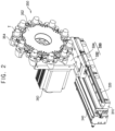
FIG. 2 is an enlarged perspective view illustrating the tool exchanging apparatus inFIG. 1 ; -
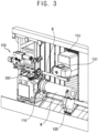
FIG. 3 is a perspective view illustrating an operation of the tool exchanging apparatus inFIG. 1 ; -
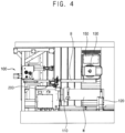
FIG. 4 is a front view illustrating the tool exchanging apparatus inFIG. 3 ; and -
FIG. 5 is a flow chart illustrating a method of exchanging a tool of a boring bar using the apparatus inFIG. 1 . - Various example embodiments will be described more fully hereinafter with reference to the accompanying drawings, in which some example embodiments are shown.
- The present invention may, however, be embodied in many different forms and should not be construed as limited to the example embodiments set forth herein. Rather, these example embodiments are provided so that this disclosure will be thorough and complete, and will fully convey the scope of the present invention to those skilled in the art. In the drawings, the sizes and relative sizes of layers and regions may be exaggerated for clarity.
- It will be understood that, although the terms first, second, third etc. may be used herein to describe various elements, components, regions, layers and/or sections, these elements, components, regions, layers and/or sections should not be limited by these terms. These terms are only used to distinguish one element, component, region, layer or section from another region, layer or section. Thus, a first element, component, region, layer or section discussed below could be termed a second element, component, region, layer or section without departing from the teachings of the present invention.
- The terminology used herein is for the purpose of describing particular example embodiments only and is not intended to be limiting of the present invention. As used herein, the singular forms "a," "an" and "the" are intended to include the plural forms as well, unless the context clearly indicates otherwise. It will be further understood that the terms "comprises" and/or "comprising," when used in this specification, specify the presence of stated features, integers, steps, operations, elements, and/or components, but do not preclude the presence or addition of one or more other features, integers, steps, operations, elements, components, and/or groups thereof.
- Unless otherwise defined, all terms (including technical and scientific terms) used herein have the same meaning as commonly understood by one of ordinary skill in the art to which this invention belongs. It will be further understood that terms, such as those defined in commonly used dictionaries, should be interpreted as having a meaning that is consistent with their meaning in the context of the relevant art and will not be interpreted in an idealized or overly formal sense unless expressly so defined herein.
-
FIG. 1 is a perspective view illustrating a boring machine with a tool exchanging apparatus. - Referring to
FIG. 1 , a boring machine may include amain shaft 110, avibration isolator 120, aspindle 130, atail stock 140, atransfer stock 150, aspindle exchange apparatus 100, a boringbar storage apparatus 200 and atool exchange apparatus 300. - The
main shaft 110 may be horizontally arranged to fix a one end of a workpiece W. The workpiece W may have a long pipe shape having a hole. Thevibration isolator 120 may support the other end of the workpiece W to prevent a vibration of the workpiece W. - The
spindle 130 may be transferred by thetransfer stock 150. Thetransfer stock 150 may transfer thespindle 130 in horizontal and vertical directions. A boring bar B may be fixed to a lower end of thetransfer stock 150. The boring bar B may machine an inner surface of the hole of the workpiece W. The boring bar B may have a bar shape having a long length. Thetail stock 140 may support an end of the boring bar B fixed to the lower end of thetransfer stock 150. - The
spindle exchange apparatus 100 may be arranged on an end of themain shaft 110. Thespindle exchange apparatus 100 may exchange thespindle 130 for a new spindle. Thespindle exchange apparatus 100 may be arranged in a direction substantially parallel to an axial direction of themain shaft 110. - The boring
bar storage apparatus 200 may be arranged over thetail stock 140. Adoor 160 may be arranged between the boringbar storage apparatus 200 and thespindle 130. The boringbar storage apparatus 200 may store a plurality of new boring bars B. The boringbar storage apparatus 200 may forward to thetransfer stock 150 to exchange the boring bar B fixed to thetransfer stock 150 for the new boring bar B. -
FIG. 2 is an enlarged perspective view illustrating the tool exchanging apparatus inFIG. 1 ,FIG. 3 is a perspective view illustrating an operation of the tool exchanging apparatus inFIG. 1 andFIG. 4 is a front view illustrating the tool exchanging apparatus inFIG. 3 . - Referring to
FIGS. 2 to 4 , thetool exchange apparatus 300 is configured to exchange a tool T installed at a front end of the boring bar B for a new tool T. Thetool exchange apparatus 300 may be arranged between themain shaft 110 and thespindle exchange apparatus 100. Thetool exchange apparatus 300 includes aframe 310, aguide rail 320, abracket 330, acylinder 340, amagazine 350 and anactuator 360. - The
frame 310 may be arranged between themain shaft 110 and thespindle exchange apparatus 100. Theframe 310 may be extended in a direction substantially perpendicular to the axial direction of themain shaft 110. Theguide rail 320 may be arranged on an upper surface of theframe 310. Theguide rail 320 may be extended in the direction substantially perpendicular to the axial direction of themain shaft 110. - The
bracket 330 may be movably connected to theguide rail 320. Thebracket 330 may include aslider 332 and a supportingplate 334. Theslider 332 may be movably connected to theguide rail 320. The supportingplate 334 may be arranged on an upper surface of theslider 332. Theslider 332 may be moved along theguide rail 320 to move thebracket 330 along the direction substantially perpendicular to the axial direction of themain shaft 110. - The
cylinder 340 may be installed at the upper surface of theframe 310. Thecylinder 340 may provide thebracket 330, particularly, theslider 332 with a straight movement force in the direction substantially perpendicular to the axial direction of themain shaft 110. Thus, theslider 332 may be moved along theguide rail 320 by the straight movement force provided from thecylinder 340. - The
magazine 350 may be arranged on a first surface of the supportingplate 334 of thebracket 330, i.e., a front surface of the supportingplate 334 oriented toward thespindle 130. Themagazine 350 may include arotation plate 352 and a plurality ofholder 354. Therotation plate 352 may be rotatably connected to the supportingplate 352 with respect to the axial direction of themain shaft 110. Theholders 354 may be arranged on an outer surface of therotation shaft 352. Theholders 352 may be configured to hole the toolsT. A holder 352 with the tool T to be exchanged among theholders 354 may be positioned at an exchange position by the rotation of therotation plate 352. - The
actuator 360 may be installed at a second surface of the supportingplate 334 opposite to the first surface. Theactuator 360 may rotate therotation shaft 352 of themagazine 350 with respect to the axial direction of themain shaft 110. In example embodiments, theactuator 360 may include a servo motor. -
FIG. 5 is a flow chart illustrating a method of exchanging a tool of a boring bar using the apparatus inFIG. 1 . - Referring to
FIGS. 1 and5 , in step ST410, the tool T may be unclamped from the boring bar B. Particularly, the boring bar B with the tool T may be moved forwardly to the exchange position. Themagazine 350 may be moved to hold the tool T. The boring bar B may then be moved backwardly to unclamp the tool T from the boring bar B. - In step ST420, the
cylinder 340 may move forwardly thebracket 330 along theguide rail 320 to position thebracket 330 on the axial direction of themain shaft 110. - In step ST430, the
actuator 360 may rotate themagazine 350 to locate theholder 352 with the tool T to be exchanged at the exchange position. - In step ST440, the
transfer stock 150 may be moved toward themagazine 350. Thus, thespindle 130 may be moved to the front of themagazine 350 to locate the front end of the boring bar B at the front of theholder 352. - In step ST450, the boring bar B may clamp the new tool T in the
holder 352. Particularly, the boring bar B may be moved forwardly to clamp the new tool T in theholder 352. Themagazine 350 may be moved to release the new tool T from themagazine 350. Thus, the boring bar B may clamp the new tool T. - After exchanging the tool T, in step ST460, the
cylinder 340 may move backwardly thebracket 330 along theguide rail 320 to return thebracket 330 at the original position. Thetransfer stock 150 may also be returned to an original position so that thespindle 130 and the boring bar B may be returned to a machining position. - According to the example embodiments, the magazine configured to hold the tools may be arranged between the main shaft and the spindle exchanging apparatus to reduce a weight of the tool. Thus, a damper may have a vibration damping capacity to decrease an impulse generated in exchanging the tool. Further, the tool may be exchanged for the new tool regardless of a size of a workpiece.
<The description of the reference numerals> 110 ; main shaft 120 ; vibration isolator 130 ; spindle 140 ; tail stock 150 ; transfer stock 160 ; door 100 ; spindle exchange apparatus 200 ; boring bar storage apparatus 300 ; tool exchange apparatus 310 ; frame 320 ; guide rail 330 ; bracket 332 ; slider 334 ; supporting plate 340 ; cylinder 350 ; magazine 352 ; rotation plate 354 ; holder 360 ; actuator
Claims (11)
- An apparatus (300) for exchanging a tool (T) of a boring bar (B), the apparatus (300) comprising:a magazine (350) configured to receive a plurality of the tools (T) to be installed at a front end of the boring bar (B);a frame (310) arranged under the magazine (350);a guide rail (320) arranged on the frame (310), the magazine (350) being movably connected to the guide rail (320); andan actuator (360) configured to rotate the magazine (350).
- The apparatus (300) of claim 1, wherein the magazine (350) comprises:a rotation plate (352) rotated by the actuator (360); anda plurality of holders (354) arranged an outer surface of the rotation plate (352) to hole the tools (T).
- The apparatus (300) of claim 1, wherein the magazine (350) is rotated with respect to an axial direction of the boring bar (B).
- The apparatus (300) of claim 1, wherein the guide rail (320) is arranged in a direction substantially perpendicular to a rotation shaft of the magazine (350).
- The apparatus (300) of claim 1, further comprising a cylinder (340) installed at the frame (310) to move the magazine (350) along the guide rail (320).
- The apparatus (300) of claim 1, further comprising a bracket (330) movably connected to the guide rail (320), the magazine (350) being rotatably connected to the bracket (330), and the actuator (360) being installed at the bracket (330).
- The apparatus (300) of claim 1, wherein the actuator (360) comprises a servo motor.
- A boring machine, comprising:a main shaft (110) which is horizontally arranged and configured to fix one end of a workpiece (W);a vibration isolator 120 configured to support another end of the workpiece (W);a spindle (130);a transfer stock (150) configured to transfer the spindle (130);a boring bar (B) fixed to a lower end of the transfer stock (150) and configured to machine the workpiece (W);a spindle exchange apparatus (100) arranged on an end of the main shaft (110) and configured to exchange the spindle (130) for a new spindle (130); andthe apparatus (300) of claim 1, wherein the magazine (350) is arranged between the spindle exchange apparatus (100) and the main shaft (110).
- A method of exchanging a tool (T) of a boring bar (B), the method comprising:arranging a magazine (350), which is configured to receive a plurality of holders (354) for holding a plurality of the tools (T), on an axial direction of a main shaft (110) in a boring machine;rotating the magazine (350) to locate a holder (354) with a new tool (T) among the holders (354) at an exchange position;arranging the boring bar (B) with the tool (T) at a front of the magazine (350); andexchanging the tool (T) for the new tool (T).
- The method of claim 9, wherein arranging the magazine (350) on the axial direction of the main shaft (110) comprises horizontally moving the magazine (350) along a guide rail (320).
- The method of claim 9, further comprising returning the magazine (350) to an original position after exchanging the tool (T) for the new tool (T).
Applications Claiming Priority (1)
| Application Number | Priority Date | Filing Date | Title |
|---|---|---|---|
| PCT/KR2020/003919 WO2021193986A1 (en) | 2020-03-23 | 2020-03-23 | Boring bar tool changer and boring bar tool changing method using same |
Publications (4)
| Publication Number | Publication Date |
|---|---|
| EP4122643A1 EP4122643A1 (en) | 2023-01-25 |
| EP4122643A4 EP4122643A4 (en) | 2023-12-20 |
| EP4122643B1 true EP4122643B1 (en) | 2025-01-22 |
| EP4122643C0 EP4122643C0 (en) | 2025-01-22 |
Family
ID=77890391
Family Applications (1)
| Application Number | Title | Priority Date | Filing Date |
|---|---|---|---|
| EP20927746.6A Active EP4122643B1 (en) | 2020-03-23 | 2020-03-23 | Boring bar tool changer and boring bar tool changing method using same |
Country Status (4)
| Country | Link |
|---|---|
| US (1) | US12678903B2 (en) |
| EP (1) | EP4122643B1 (en) |
| CN (1) | CN115335188B (en) |
| WO (1) | WO2021193986A1 (en) |
Families Citing this family (2)
| Publication number | Priority date | Publication date | Assignee | Title |
|---|---|---|---|---|
| CN116141005B (en) * | 2023-04-17 | 2023-08-18 | 池州中科裕华汽车科技有限公司 | Numerical control machining center for belt pulley |
| JP7573096B1 (en) | 2023-12-26 | 2024-10-24 | Dmg森精機株式会社 | Tool transport device and machining system |
Family Cites Families (32)
| Publication number | Priority date | Publication date | Assignee | Title |
|---|---|---|---|---|
| CH481717A (en) * | 1968-02-24 | 1969-11-30 | Mueller Max Brinker Maschf | Machine tool, in particular lathe |
| DE8421945U1 (en) | 1984-07-23 | 1984-10-31 | Kastner, Hermann, Dipl.-Ing., 7140 Ludwigsburg | DIVISIBLE TOOL FOR CUTTING MACHINING |
| JPS6362629A (en) * | 1986-09-02 | 1988-03-18 | Kyushu Toshiba Kikai Kk | Deep hole drilling machine |
| JP2532663Y2 (en) | 1990-06-29 | 1997-04-16 | 三井精機工業株式会社 | Automatic change equipment for line boring bar |
| US6149561A (en) * | 1999-03-16 | 2000-11-21 | Unova Ip Corp | Machine and method for flexible line boring |
| JP2002307218A (en) * | 2001-04-12 | 2002-10-23 | Toyoda Mach Works Ltd | High-speed boring shaft head that can handle multiple diameters |
| JP3908495B2 (en) * | 2001-09-10 | 2007-04-25 | ヤマザキマザック株式会社 | Boring bar support device and machine tool |
| US7144355B2 (en) * | 2002-07-03 | 2006-12-05 | Toshiba Kikai Kabushiki Kaisha | Tool replacement method and nut driver for machine tools |
| JP4632344B2 (en) * | 2003-12-18 | 2011-02-16 | 株式会社森精機製作所 | Machine tool with a boring bar magazine |
| JP4342928B2 (en) * | 2003-12-25 | 2009-10-14 | 株式会社森精機製作所 | Tool changer for machine tools |
| DE102005043399B4 (en) * | 2005-09-08 | 2009-06-10 | Tixbo Tiefbohr-Center Gmbh & Co.Kg | Device for machining with automatic tool change and method for automatically changing tools on the device for machining |
| KR100750594B1 (en) * | 2006-10-26 | 2007-08-21 | 한국기계연구원 | Mobile Armless ATC Machining Center with Semicircular Magazine |
| KR100779805B1 (en) | 2006-12-14 | 2007-11-27 | 두산인프라코어 주식회사 | Opening and closing of the ATC door in conjunction with the drive of the tool magazine |
| JP5026884B2 (en) | 2007-08-04 | 2012-09-19 | 株式会社森精機製作所 | Machine tool with automatic tool changer |
| KR100938081B1 (en) | 2007-10-12 | 2010-01-21 | 현대위아 주식회사 | Umbrella type automatic tool changer with integrated magazine and ATC door |
| JP2009178804A (en) * | 2008-01-31 | 2009-08-13 | Mori Seiki Co Ltd | Machine tool having a boring bar magazine and boring bar magazine |
| CN201346715Y (en) * | 2009-01-24 | 2009-11-18 | 苏州江南电梯(集团)有限公司 | Machining center provided with composite tool magazine |
| CN202556120U (en) * | 2011-12-28 | 2012-11-28 | 南京宁庆数控机床制造有限公司 | Rear end face mounted tool changer for gantry machining center |
| ITTV20120043A1 (en) * | 2012-03-21 | 2013-09-22 | Almerino Canuto | CANNON DRILL CHANGE DEVICE FOR DEEP HOLE DRILLS |
| TW201343284A (en) * | 2012-04-23 | 2013-11-01 | Alex Tech Machinery Ind Co Ltd | Composite tailstock apparatus for deep hole processing of machine tool |
| JP2015182139A (en) * | 2014-03-20 | 2015-10-22 | 三菱重工業株式会社 | Machine tool |
| CN104959865A (en) * | 2015-04-29 | 2015-10-07 | 佛山市普拉迪数控科技有限公司 | Bamboo hat tool magazine in high tool changing precision |
| JP5956040B1 (en) * | 2015-09-07 | 2016-07-20 | Dmg森精機株式会社 | Machine Tools |
| CN106914634A (en) * | 2015-12-25 | 2017-07-04 | 茅保富 | Adjustable boring tool disk |
| JP6886166B2 (en) * | 2016-04-22 | 2021-06-16 | 中村留精密工業株式会社 | Tool changer and change method |
| KR101850759B1 (en) | 2016-12-19 | 2018-06-07 | 주식회사 스맥 | machine tool |
| EP3456466B1 (en) * | 2017-09-14 | 2022-04-06 | Rollomatic S.A. | Tool magazine and method for changing tools |
| DE102017125316A1 (en) * | 2017-10-27 | 2019-05-02 | Moroff & Baierl Gmbh | Device for exchanging a part of a tool and a hollow milling tool |
| KR20190083104A (en) * | 2018-01-03 | 2019-07-11 | 두산공작기계 주식회사 | Tool magazine of machine tool |
| KR102768668B1 (en) | 2019-03-05 | 2025-02-18 | 주식회사 디엔솔루션즈 | Apparatus for exchanging a tool of a boring bar and method of exchanging a tool of a boring bar using the same |
| KR102598071B1 (en) * | 2019-03-08 | 2023-11-03 | 주식회사 디엔솔루션즈 | Auto toool changer and method for controlling the same and machine tool having the same |
| JP7808947B2 (en) * | 2021-10-21 | 2026-01-30 | 花王株式会社 | Oil-based cosmetics |
-
2020
- 2020-03-23 EP EP20927746.6A patent/EP4122643B1/en active Active
- 2020-03-23 CN CN202080098990.0A patent/CN115335188B/en active Active
- 2020-03-23 US US17/913,133 patent/US12678903B2/en active Active
- 2020-03-23 WO PCT/KR2020/003919 patent/WO2021193986A1/en not_active Ceased
Also Published As
| Publication number | Publication date |
|---|---|
| CN115335188A (en) | 2022-11-11 |
| WO2021193986A1 (en) | 2021-09-30 |
| EP4122643C0 (en) | 2025-01-22 |
| US20230191548A1 (en) | 2023-06-22 |
| CN115335188B (en) | 2024-06-18 |
| EP4122643A1 (en) | 2023-01-25 |
| EP4122643A4 (en) | 2023-12-20 |
| US12678903B2 (en) | 2026-07-14 |
Similar Documents
| Publication | Publication Date | Title |
|---|---|---|
| US5172464A (en) | Machine tool | |
| US11167354B2 (en) | Machine tool, in particular lathe | |
| EP2982473B1 (en) | Automatic tool exchanging device for angle tool holder for 5-face machining in vertical machining center | |
| EP2163334B2 (en) | Machine comprising a drum having workpiece supporting spindles movable in the direction of the longitudinal axis of the drum | |
| JP2005186186A (en) | Tool changer for machine tools | |
| JP2018001364A (en) | Machine tool unit | |
| EP4122643A1 (en) | Boring bar tool changer and boring bar tool changing method using same | |
| US10661403B2 (en) | Tool changer, machine tool, and method for changing tool | |
| KR101796321B1 (en) | Automatic tool changer for machine tool | |
| JP6525737B2 (en) | Machine Tools | |
| KR102768668B1 (en) | Apparatus for exchanging a tool of a boring bar and method of exchanging a tool of a boring bar using the same | |
| CN101508028B (en) | Machine tool | |
| JP4741351B2 (en) | Small lathe | |
| JP5374195B2 (en) | Machine Tools | |
| JP3249741B2 (en) | Machine tools and tool changers | |
| WO2022254719A1 (en) | Work machine | |
| JP2004261935A (en) | Lathe provided with steady rest device for work | |
| CN222175953U (en) | Automatic processing device for automobile shock absorber piston production line | |
| US20240307971A1 (en) | Machine tool, in particular a lathe, and method for machining workpieces using a machine tool | |
| JP7466068B2 (en) | Tool Clamping Device | |
| JP7733584B2 (en) | Additional tool magazine device and machine tool | |
| JP6825153B1 (en) | Magazines and machine tools | |
| JPH06246514A (en) | Automatic lathe | |
| JP2008110425A (en) | Tool magazine and machine tool | |
| JPH10128637A (en) | Tool transport method for matrix type tool magazine and matrix type tool magazine |
Legal Events
| Date | Code | Title | Description |
|---|---|---|---|
| STAA | Information on the status of an ep patent application or granted ep patent |
Free format text: STATUS: THE INTERNATIONAL PUBLICATION HAS BEEN MADE |
|
| PUAI | Public reference made under article 153(3) epc to a published international application that has entered the european phase |
Free format text: ORIGINAL CODE: 0009012 |
|
| STAA | Information on the status of an ep patent application or granted ep patent |
Free format text: STATUS: REQUEST FOR EXAMINATION WAS MADE |
|
| 17P | Request for examination filed |
Effective date: 20221020 |
|
| AK | Designated contracting states |
Kind code of ref document: A1 Designated state(s): AL AT BE BG CH CY CZ DE DK EE ES FI FR GB GR HR HU IE IS IT LI LT LU LV MC MK MT NL NO PL PT RO RS SE SI SK SM TR |
|
| DAV | Request for validation of the european patent (deleted) | ||
| DAX | Request for extension of the european patent (deleted) | ||
| A4 | Supplementary search report drawn up and despatched |
Effective date: 20231122 |
|
| RIC1 | Information provided on ipc code assigned before grant |
Ipc: B23B 29/02 20060101ALI20231116BHEP Ipc: B23Q 3/155 20060101AFI20231116BHEP |
|
| GRAP | Despatch of communication of intention to grant a patent |
Free format text: ORIGINAL CODE: EPIDOSNIGR1 |
|
| STAA | Information on the status of an ep patent application or granted ep patent |
Free format text: STATUS: GRANT OF PATENT IS INTENDED |
|
| INTG | Intention to grant announced |
Effective date: 20240903 |
|
| GRAS | Grant fee paid |
Free format text: ORIGINAL CODE: EPIDOSNIGR3 |
|
| GRAA | (expected) grant |
Free format text: ORIGINAL CODE: 0009210 |
|
| STAA | Information on the status of an ep patent application or granted ep patent |
Free format text: STATUS: THE PATENT HAS BEEN GRANTED |
|
| AK | Designated contracting states |
Kind code of ref document: B1 Designated state(s): AL AT BE BG CH CY CZ DE DK EE ES FI FR GB GR HR HU IE IS IT LI LT LU LV MC MK MT NL NO PL PT RO RS SE SI SK SM TR |
|
| REG | Reference to a national code |
Ref country code: GB Ref legal event code: FG4D |
|
| REG | Reference to a national code |
Ref country code: CH Ref legal event code: EP |
|
| REG | Reference to a national code |
Ref country code: IE Ref legal event code: FG4D |
|
| REG | Reference to a national code |
Ref country code: DE Ref legal event code: R096 Ref document number: 602020045382 Country of ref document: DE |
|
| U01 | Request for unitary effect filed |
Effective date: 20250122 |
|
| U07 | Unitary effect registered |
Designated state(s): AT BE BG DE DK EE FI FR IT LT LU LV MT NL PT RO SE SI Effective date: 20250129 |
|
| U20 | Renewal fee for the european patent with unitary effect paid |
Year of fee payment: 6 Effective date: 20250221 |
|
| PG25 | Lapsed in a contracting state [announced via postgrant information from national office to epo] |
Ref country code: RS Free format text: LAPSE BECAUSE OF FAILURE TO SUBMIT A TRANSLATION OF THE DESCRIPTION OR TO PAY THE FEE WITHIN THE PRESCRIBED TIME-LIMIT Effective date: 20250422 |
|
| PG25 | Lapsed in a contracting state [announced via postgrant information from national office to epo] |
Ref country code: PL Free format text: LAPSE BECAUSE OF FAILURE TO SUBMIT A TRANSLATION OF THE DESCRIPTION OR TO PAY THE FEE WITHIN THE PRESCRIBED TIME-LIMIT Effective date: 20250122 |
|
| PG25 | Lapsed in a contracting state [announced via postgrant information from national office to epo] |
Ref country code: ES Free format text: LAPSE BECAUSE OF FAILURE TO SUBMIT A TRANSLATION OF THE DESCRIPTION OR TO PAY THE FEE WITHIN THE PRESCRIBED TIME-LIMIT Effective date: 20250122 |
|
| PG25 | Lapsed in a contracting state [announced via postgrant information from national office to epo] |
Ref country code: NO Free format text: LAPSE BECAUSE OF FAILURE TO SUBMIT A TRANSLATION OF THE DESCRIPTION OR TO PAY THE FEE WITHIN THE PRESCRIBED TIME-LIMIT Effective date: 20250422 Ref country code: IS Free format text: LAPSE BECAUSE OF FAILURE TO SUBMIT A TRANSLATION OF THE DESCRIPTION OR TO PAY THE FEE WITHIN THE PRESCRIBED TIME-LIMIT Effective date: 20250522 |
|
| PG25 | Lapsed in a contracting state [announced via postgrant information from national office to epo] |
Ref country code: HR Free format text: LAPSE BECAUSE OF FAILURE TO SUBMIT A TRANSLATION OF THE DESCRIPTION OR TO PAY THE FEE WITHIN THE PRESCRIBED TIME-LIMIT Effective date: 20250122 |
|
| PG25 | Lapsed in a contracting state [announced via postgrant information from national office to epo] |
Ref country code: GR Free format text: LAPSE BECAUSE OF FAILURE TO SUBMIT A TRANSLATION OF THE DESCRIPTION OR TO PAY THE FEE WITHIN THE PRESCRIBED TIME-LIMIT Effective date: 20250423 |
|
| PG25 | Lapsed in a contracting state [announced via postgrant information from national office to epo] |
Ref country code: SM Free format text: LAPSE BECAUSE OF FAILURE TO SUBMIT A TRANSLATION OF THE DESCRIPTION OR TO PAY THE FEE WITHIN THE PRESCRIBED TIME-LIMIT Effective date: 20250122 |
|
| PG25 | Lapsed in a contracting state [announced via postgrant information from national office to epo] |
Ref country code: MC Free format text: LAPSE BECAUSE OF FAILURE TO SUBMIT A TRANSLATION OF THE DESCRIPTION OR TO PAY THE FEE WITHIN THE PRESCRIBED TIME-LIMIT Effective date: 20250122 |
|
| PG25 | Lapsed in a contracting state [announced via postgrant information from national office to epo] |
Ref country code: CZ Free format text: LAPSE BECAUSE OF FAILURE TO SUBMIT A TRANSLATION OF THE DESCRIPTION OR TO PAY THE FEE WITHIN THE PRESCRIBED TIME-LIMIT Effective date: 20250122 |
|
| REG | Reference to a national code |
Ref country code: CH Ref legal event code: H13 Free format text: ST27 STATUS EVENT CODE: U-0-0-H10-H13 (AS PROVIDED BY THE NATIONAL OFFICE) Effective date: 20251023 |
|
| PG25 | Lapsed in a contracting state [announced via postgrant information from national office to epo] |
Ref country code: SK Free format text: LAPSE BECAUSE OF FAILURE TO SUBMIT A TRANSLATION OF THE DESCRIPTION OR TO PAY THE FEE WITHIN THE PRESCRIBED TIME-LIMIT Effective date: 20250122 |
|
| PLBE | No opposition filed within time limit |
Free format text: ORIGINAL CODE: 0009261 |
|
| STAA | Information on the status of an ep patent application or granted ep patent |
Free format text: STATUS: NO OPPOSITION FILED WITHIN TIME LIMIT |
|
| 26N | No opposition filed |
Effective date: 20251023 |
|
| PG25 | Lapsed in a contracting state [announced via postgrant information from national office to epo] |
Ref country code: CH Free format text: LAPSE BECAUSE OF NON-PAYMENT OF DUE FEES Effective date: 20250331 |
|
| PG25 | Lapsed in a contracting state [announced via postgrant information from national office to epo] |
Ref country code: IE Free format text: LAPSE BECAUSE OF NON-PAYMENT OF DUE FEES Effective date: 20250323 |
|
| U20 | Renewal fee for the european patent with unitary effect paid |
Year of fee payment: 7 Effective date: 20260209 |
|
| PGFP | Annual fee paid to national office [announced via postgrant information from national office to epo] |
Ref country code: GB Payment date: 20260106 Year of fee payment: 7 |
|
| PG25 | Lapsed in a contracting state [announced via postgrant information from national office to epo] |
Ref country code: CY Free format text: LAPSE BECAUSE OF FAILURE TO SUBMIT A TRANSLATION OF THE DESCRIPTION OR TO PAY THE FEE WITHIN THE PRESCRIBED TIME-LIMIT Effective date: 20250122 |
|
| PG25 | Lapsed in a contracting state [announced via postgrant information from national office to epo] |
Ref country code: TR Free format text: LAPSE BECAUSE OF FAILURE TO SUBMIT A TRANSLATION OF THE DESCRIPTION OR TO PAY THE FEE WITHIN THE PRESCRIBED TIME-LIMIT Effective date: 20250122 |