EP4122636B1 - Laser welding device - Google Patents
Laser welding device Download PDFInfo
- Publication number
- EP4122636B1 EP4122636B1 EP20926072.8A EP20926072A EP4122636B1 EP 4122636 B1 EP4122636 B1 EP 4122636B1 EP 20926072 A EP20926072 A EP 20926072A EP 4122636 B1 EP4122636 B1 EP 4122636B1
- Authority
- EP
- European Patent Office
- Prior art keywords
- cylindrical lens
- lens
- power density
- density spot
- spot
- Prior art date
- Legal status (The legal status is an assumption and is not a legal conclusion. Google has not performed a legal analysis and makes no representation as to the accuracy of the status listed.)
- Active
Links
Images



Classifications
-
- B—PERFORMING OPERATIONS; TRANSPORTING
- B23—MACHINE TOOLS; METAL-WORKING NOT OTHERWISE PROVIDED FOR
- B23K—SOLDERING OR UNSOLDERING; WELDING; CLADDING OR PLATING BY SOLDERING OR WELDING; CUTTING BY APPLYING HEAT LOCALLY, e.g. FLAME CUTTING; WORKING BY LASER BEAM
- B23K26/00—Working by laser beam, e.g. welding, cutting or boring
- B23K26/02—Positioning or observing the workpiece, e.g. with respect to the point of impact; Aligning, aiming or focusing the laser beam
- B23K26/06—Shaping the laser beam, e.g. by masks or multi-focusing
- B23K26/064—Shaping the laser beam, e.g. by masks or multi-focusing by means of optical elements, e.g. lenses, mirrors or prisms
-
- B—PERFORMING OPERATIONS; TRANSPORTING
- B23—MACHINE TOOLS; METAL-WORKING NOT OTHERWISE PROVIDED FOR
- B23K—SOLDERING OR UNSOLDERING; WELDING; CLADDING OR PLATING BY SOLDERING OR WELDING; CUTTING BY APPLYING HEAT LOCALLY, e.g. FLAME CUTTING; WORKING BY LASER BEAM
- B23K26/00—Working by laser beam, e.g. welding, cutting or boring
- B23K26/02—Positioning or observing the workpiece, e.g. with respect to the point of impact; Aligning, aiming or focusing the laser beam
- B23K26/06—Shaping the laser beam, e.g. by masks or multi-focusing
- B23K26/062—Shaping the laser beam, e.g. by masks or multi-focusing by direct control of the laser beam
- B23K26/0626—Energy control of the laser beam
-
- B—PERFORMING OPERATIONS; TRANSPORTING
- B23—MACHINE TOOLS; METAL-WORKING NOT OTHERWISE PROVIDED FOR
- B23K—SOLDERING OR UNSOLDERING; WELDING; CLADDING OR PLATING BY SOLDERING OR WELDING; CUTTING BY APPLYING HEAT LOCALLY, e.g. FLAME CUTTING; WORKING BY LASER BEAM
- B23K26/00—Working by laser beam, e.g. welding, cutting or boring
- B23K26/02—Positioning or observing the workpiece, e.g. with respect to the point of impact; Aligning, aiming or focusing the laser beam
- B23K26/06—Shaping the laser beam, e.g. by masks or multi-focusing
- B23K26/064—Shaping the laser beam, e.g. by masks or multi-focusing by means of optical elements, e.g. lenses, mirrors or prisms
- B23K26/0648—Shaping the laser beam, e.g. by masks or multi-focusing by means of optical elements, e.g. lenses, mirrors or prisms comprising lenses
-
- B—PERFORMING OPERATIONS; TRANSPORTING
- B23—MACHINE TOOLS; METAL-WORKING NOT OTHERWISE PROVIDED FOR
- B23K—SOLDERING OR UNSOLDERING; WELDING; CLADDING OR PLATING BY SOLDERING OR WELDING; CUTTING BY APPLYING HEAT LOCALLY, e.g. FLAME CUTTING; WORKING BY LASER BEAM
- B23K26/00—Working by laser beam, e.g. welding, cutting or boring
- B23K26/02—Positioning or observing the workpiece, e.g. with respect to the point of impact; Aligning, aiming or focusing the laser beam
- B23K26/06—Shaping the laser beam, e.g. by masks or multi-focusing
- B23K26/073—Shaping the laser spot
-
- B—PERFORMING OPERATIONS; TRANSPORTING
- B23—MACHINE TOOLS; METAL-WORKING NOT OTHERWISE PROVIDED FOR
- B23K—SOLDERING OR UNSOLDERING; WELDING; CLADDING OR PLATING BY SOLDERING OR WELDING; CUTTING BY APPLYING HEAT LOCALLY, e.g. FLAME CUTTING; WORKING BY LASER BEAM
- B23K26/00—Working by laser beam, e.g. welding, cutting or boring
- B23K26/02—Positioning or observing the workpiece, e.g. with respect to the point of impact; Aligning, aiming or focusing the laser beam
- B23K26/06—Shaping the laser beam, e.g. by masks or multi-focusing
- B23K26/073—Shaping the laser spot
- B23K26/0732—Shaping the laser spot into a rectangular shape
-
- B—PERFORMING OPERATIONS; TRANSPORTING
- B23—MACHINE TOOLS; METAL-WORKING NOT OTHERWISE PROVIDED FOR
- B23K—SOLDERING OR UNSOLDERING; WELDING; CLADDING OR PLATING BY SOLDERING OR WELDING; CUTTING BY APPLYING HEAT LOCALLY, e.g. FLAME CUTTING; WORKING BY LASER BEAM
- B23K26/00—Working by laser beam, e.g. welding, cutting or boring
- B23K26/02—Positioning or observing the workpiece, e.g. with respect to the point of impact; Aligning, aiming or focusing the laser beam
- B23K26/06—Shaping the laser beam, e.g. by masks or multi-focusing
- B23K26/073—Shaping the laser spot
- B23K26/0734—Shaping the laser spot into an annular shape
-
- B—PERFORMING OPERATIONS; TRANSPORTING
- B23—MACHINE TOOLS; METAL-WORKING NOT OTHERWISE PROVIDED FOR
- B23K—SOLDERING OR UNSOLDERING; WELDING; CLADDING OR PLATING BY SOLDERING OR WELDING; CUTTING BY APPLYING HEAT LOCALLY, e.g. FLAME CUTTING; WORKING BY LASER BEAM
- B23K26/00—Working by laser beam, e.g. welding, cutting or boring
- B23K26/02—Positioning or observing the workpiece, e.g. with respect to the point of impact; Aligning, aiming or focusing the laser beam
- B23K26/06—Shaping the laser beam, e.g. by masks or multi-focusing
- B23K26/073—Shaping the laser spot
- B23K26/0738—Shaping the laser spot into a linear shape
-
- B—PERFORMING OPERATIONS; TRANSPORTING
- B23—MACHINE TOOLS; METAL-WORKING NOT OTHERWISE PROVIDED FOR
- B23K—SOLDERING OR UNSOLDERING; WELDING; CLADDING OR PLATING BY SOLDERING OR WELDING; CUTTING BY APPLYING HEAT LOCALLY, e.g. FLAME CUTTING; WORKING BY LASER BEAM
- B23K26/00—Working by laser beam, e.g. welding, cutting or boring
- B23K26/20—Bonding
- B23K26/21—Bonding by welding
-
- G—PHYSICS
- G02—OPTICS
- G02B—OPTICAL ELEMENTS, SYSTEMS OR APPARATUS
- G02B13/00—Optical objectives specially designed for the purposes specified below
- G02B13/08—Anamorphotic objectives
- G02B13/12—Anamorphotic objectives with variable magnification
-
- G—PHYSICS
- G02—OPTICS
- G02B—OPTICAL ELEMENTS, SYSTEMS OR APPARATUS
- G02B3/00—Simple or compound lenses
-
- G—PHYSICS
- G02—OPTICS
- G02B—OPTICAL ELEMENTS, SYSTEMS OR APPARATUS
- G02B3/00—Simple or compound lenses
- G02B3/02—Simple or compound lenses with non-spherical faces
- G02B3/06—Simple or compound lenses with non-spherical faces with cylindrical or toric faces
-
- G—PHYSICS
- G02—OPTICS
- G02B—OPTICAL ELEMENTS, SYSTEMS OR APPARATUS
- G02B7/00—Mountings, adjusting means, or light-tight connections, for optical elements
- G02B7/02—Mountings, adjusting means, or light-tight connections, for optical elements for lenses
- G02B7/04—Mountings, adjusting means, or light-tight connections, for optical elements for lenses with mechanism for focusing or varying magnification
- G02B7/10—Mountings, adjusting means, or light-tight connections, for optical elements for lenses with mechanism for focusing or varying magnification by relative axial movement of several lenses, e.g. of varifocal objective lens
-
- H—ELECTRICITY
- H01—ELECTRIC ELEMENTS
- H01S—DEVICES USING THE PROCESS OF LIGHT AMPLIFICATION BY STIMULATED EMISSION OF RADIATION [LASER] TO AMPLIFY OR GENERATE LIGHT; DEVICES USING STIMULATED EMISSION OF ELECTROMAGNETIC RADIATION IN WAVE RANGES OTHER THAN OPTICAL
- H01S3/00—Lasers, i.e. devices using stimulated emission of electromagnetic radiation in the infrared, visible or ultraviolet wave range
- H01S3/005—Optical devices external to the laser cavity, specially adapted for lasers, e.g. for homogenisation of the beam or for manipulating laser pulses, e.g. pulse shaping
Definitions
- the present invention relates to the field of laser machining, and more particularly to a laser welding apparatus according to the preamble of claim 1 (see for example US 2019/389001 A1 ).
- an objective of the present invention is to provide a laser apparatus that is applicable, in a flexible way, to various lasers and is operable with high durability.
- the present invention provides, according to claim 1, for a laser welding head that uses a collimation lens and a condensing lens to form an image with laser light emerging from an optical fiber, a hollowed convex cylindrical lens or a concave cylindrical lens having a longer focal distance to be arranged in front of the collimation lens (or behind the collimation lens or behind the condensing lens).
- the hollowed portion allows a light beam around a center of the optical fiber to pass therethrough to be collimated and condensed by the welding head to form a high power density spot.
- a light beam that distantly deviates from the center of the optical fiber is subjected to change of the location of the focal point by means of the convex cylindrical lens/the concave cylindrical lens having a relatively long focal distance so as to deviate from the focal point of the light beam passing through the hollowed portion to thereby form a circular high power density spot and an elongate strip like lower power density spot overlapping each other on a welding plane.
- the high power density spot is small and may achieve keyhole welding.
- a light beam around a center of the optical fiber passes, without loss, a void or hollowed portion of the cylindrical lens that is arranged in front of or behind the collimation lens or behind the condensing lens to get focused on a workpiece surface, without being subject to any influence, while remaining light beams that transmit through a curved portion of the cylindrical lens changes a beam angle thereof in transmission through the optical axis in individual direction due to the curved surface of the cylindrical lens and after convergence of the light beams, the locations of focal points in the individual direction shift relative to the location of the focal point of the central light beam, either moving frontwards or moving rearwards, and therefore two spots are formed on the surface of the workpiece, one being a high power density spot, and the other being a lower power density spot. This prevents the occurrence of welding cracking and may thus help enhance quality and yield.
- the present invention by changing a distance between an output end of the optical fiber and the cylindrical lens and, a distance between the cylindrical lens and the condensing lens, it is possible to adjust a power ratio between the high power density spot and the lower power density spot.
- the present invention by changing the location of the cylindrical lens to cause the optical axis of the cylindrical lens to deviate from the original optical axis, it is possible to adjust a relative position between the high power density spot and the lower power density spot for finely changing the process condition to further enhance the quality of welding.
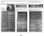
- Table 1 shows results of the embodiments and the prior art.
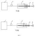
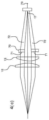
- FIG 1 is an overall structure diagram showing a laser apparatus according to the instant embodiment, wherein 1(a) is a side elevational view and 1(b) is a top view.
- Mixed light 4 produced as coming from a fiber laser 1 and transmitting through a single-core optical fiber 2 to pass through a barrel is applied to conduct welding on a welding object 5.
- the barrel is a mixing emergent barrel 3, which functions for beam shaping and converging of the emergent light coming from the single-core optical fiber, in order to realize a combined/hybrid welding of high power density spot and/or lower power density spot.
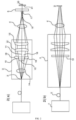
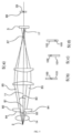
- FIG 2(a) is a side elevational view of the basic structure of the laser apparatus according to the first embodiment.
- the laser apparatus includes a convex cylindrical lens 10 added between the optical fiber 2 and a collimation lens 12.
- the cylindrical lens 10, the collimation lens 12, and a condensing lens 13 are sequentially arranged on the same optical axis 11 as the single-core optical fiber 2.
- laser light 16 that passes through a hollowed portion 15 of the convex cylindrical lens 10 is collimated by the collimation lens 12 and then condensed by the condensing lens 13, and a high-luminance focal point 20 that satisfies keyhole welding can be formed on a condensing point 17.
- an incident angle of the laser light 16 that transmits through a non-hollowed convex lens portion 18 of the convex cylindrical lens 10, after transmitting through the collimation lens 12, is slightly changed, by a plano-convex cylindrical lens, with respect to the condensing lens 13.
- the light beam After transmitting through the collimation lens 12, the light beam is converged at a site 19 that is slightly frontward of the light converging point 17, and then diffused again after the condensation. Due to be out of focusing, a lower power density spot 21, compared to the high power density of the condensing point 17, is formed on a working surface 5.
- the lower power density spot 21 functions for increasing temperature and preheating of a workpiece before keyhole welding, and allowing a cooling rate of the workpiece to slow down after welding, so as to provide an effect of preventing cracking generated after welding.
- Such an intensity distribution can be varied by having the cylindrical lens 10 moved frontward or rearward, so as to better the welding condition.
- FIG 2(b) is a top plan view of the basic structure diagram of the laser apparatus according to the first embodiment.
- the cylindrical lens 10 shows no variation of curvature, and for laser light that pass through the hollowed portion 15 or that transmitting through the non-hollowed portion 18, the incident angle of the laser light does not change, so that no condensing point is formed on the site 19 in this direction, all being converged on the same focal plane as the condensing point 17.
- the cylindrical lens is a mixed spot 21 of the high power density spot and the lower power density spot.
- FIG 2(c) is a side elevational view of a basic structure diagram of the laser apparatus according to the first embodiment that includes a concave cylindrical lens 30.
- the lens is convex or concave, and common arrangements are omitted.
- the laser light 32 that transmits through a curved portion 31 that is not a hollowed portion of the cylindrical lens 30, after transmitting through the collimation lens 12, is incident to the condensing lens 13 and an incident angle of the laser light 32 is slightly expanded, so that location of the focal point relative to the condensing point 17 changes.
- FIG. 17 A top plan view of the basic structure diagram of the laser apparatus of the first embodiment including the concave cylindrical lens 30 is the same as FIG 2(b) , and details will be omitted here.
- FIG 3(a) is a side elevational view of a basic structure diagram of a laser apparatus according to a second embodiment in which a convex cylindrical lens 40 is arranged between the collimation lens 12 and the condensing lens 13.
- the collimation lens 12, the convex cylindrical lens 40, and the condensing lens 13 are sequentially arranged on the same optical axis 11 as the single-core optical fiber 2.
- Laser light 14 emerging from the single-core optical fiber 2 is collimated by the collimation lens 12, and then laser light 42 that passes through a hollowed portion 41 of the cylindrical lens 40 is condensed by the condensing lens 13, so as to form a high-luminance focal point 20 that satisfies keyhole welding on a condensing point 17.
- laser light 44 that transmits through a non-hollowed portion 43 with a curved surface of the convex cylindrical lens 40 is incident to the condensing lens 13 and an incident angle of the laser light 44 is slightly changed, and thus converged at a site 19 that is slightly frontward of the converging point 17 and is then diffused again, and being out of focusing, a lower power density spot 45, compared to the high power density of the condensing point 17, is formed on a working surface 5.
- FIG 3(b) is a top plan view of the basic structure diagram of the laser apparatus according to the second embodiment.
- the convex cylindrical lens 40 shows no variation of curvature, and for laser light that passes through the hollowed portion 41 or that transmitting through the non-hollowed portion 43, the incident angle of the laser light does not change, so that no condensing point is formed on the site 19 in this direction, all being converged on the same focal plane as the condensing point 17.
- the cylindrical lens is a mixed spot 46 of the high power density spot and the lower power density spot.
- FIG 3(c) is a side elevational view of a basic structure diagram of the laser apparatus according to the second embodiment that includes a concave cylindrical lens 50.
- the lens is convex or concave, and common arrangements are omitted.
- the laser light 52 that transmits through a non- hollowed portion 51 with a curved surface of the concave cylindrical lens 50 is incident to the condensing lens 13 and an incident angle of the laser light 52 is slightly expanded, so that the location of the focal point relative to the condensing point 17 changes.
- FIG. 17 A top plan view of the basic structure diagram of the laser apparatus of the second embodiment including the concave cylindrical lens 50 is the same as FIG 3(b) , and details will be omitted here.
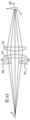
- FIG 4(a) is a side elevational view of a basic structure diagram of a laser apparatus according to a third embodiment in which a convex cylindrical lens 60 is arranged after the condensing lens 13.
- the collimation lens 12, the condensing lens 13, and the convex cylindrical lens 60 are sequentially arranged on the same optical axis 11 as the single-core optical fiber 2.
- Laser light 14 emerging from the single-core optical fiber 2 is collimated by the collimation lens 12 and then converged by the focusing lens 13.
- Laser light 62 of a portion of the converged light beam passes through a hollowed portion 61 of the convex cylindrical lens 60 so as to form a high-luminance focal point 20 that satisfies keyhole welding on a condensing point 17.
- an exit angle of laser light 64 that transmits through a non-hollowed portion 63 with a curved surface of the convex cylindrical lens 60 is slightly changed and the laser light 64 exiting from the non-hollowed portion 63 is thus converged at a site 19 that is slightly frontward of the converging point and then diffused again. Due to being out of focusing, a lower power density spot 65, compared to the high power density of the condensing point 17, is formed on a working surface 5.
- Such an intensity distribution can be varied by having the cylindrical lens 60 moved frontward or rearward, so as to better the welding condition.
- FIG 4(b) is a top plan view of the basic structure diagram of the laser apparatus according to the third embodiment.
- the convex cylindrical lens 60 shows no variation of curvature, and for laser light that passes through the hollowed portion 61 or that transmitting through the non-hollowed portion 63, the exit angle of the laser light does not change, so that no condensing point is formed on the site 19 in this direction, all being converged on the same focal plane as the condensing point 17.
- the cylindrical lens is a mixed spot 66 of the high power density spot and the lower power density spot.
- FIG 4(c) is a side elevational view of a basic structure diagram of the laser apparatus according to the third embodiment that includes a concave cylindrical lens 70.
- a difference from FIG 4(a) is that the lens 60 in FIG 4(a) is convex while the lens 70 in FIG 4(c) is concave, and common arrangements are omitted.
- an exit angle of the laser light 72 that transmits through a non-hollowed portion 71 with a curved surface of the concave cylindrical lens 70 is slightly changed so that the location of the focal point relative to the condensing point 17 changes.
- FIG. 7 A top plan view of the basic structure diagram of the laser apparatus of the third embodiment including the concave cylindrical lens 70 is the same as FIG 4(b) , and details will be omitted here.
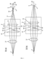
- FIG 5(a) is a side elevational view of a basic structure diagram of a laser apparatus in which the location of a cylindrical lens 80 is varied.
- an optical axis 81 of the cylindrical lens 80 deviates from the optical axis 11 of the single-core optical fiber 2, while the axis of collimation lens 12 and the condensing lens 13 are coincident with the optical axis 11 of the single-core optical fiber 2.
- laser light 83 of a portion thereof passes through a hollowed portion 82 of the cylindrical lens 80 and is collimated by the collimation lens 12 to be then focused by the focusing lens 13, so as to form a high-luminance focal point 20 that satisfies keyhole welding on a condensing point 17.
- an exit angle of laser light 85 that transmits through a non-hollowed portion 84 with a curved surface of the cylindrical lens 80 is slightly changed, and since the optical axis 81 of the cylindrical lens 80 deviates from the main optical axis 11, a condensing point location of the converging point 87 is not just moved frontwards or rearwards and is also deviating from the optical axis in an upward/downward direction. Due to being out of focusing, a lower power density spot 86, compared to the high power density of the condensing point 17, is formed on a working surface 5.
- the fourth embodiment provides a universal way that is applicable to the first, second, and third embodiments, and is also applicable to a flat-top cylindrical lens, a partial flat-top cylindrical lens, a multi-curvature cylindrical lens, and an aspheric cylindrical lens.
- a flat-top cylindrical lens By changing the upward/downward location of the cylindrical lens 80, shifting of a relative position between the high power density spot 20 and the lower power density spot 86 occurs and can greatly change the welding condition.
- FIG 5(b) is a diagram showing a mixed spot of a high power density spot and a lower power density spot in case that an optical axis of a cylindrical lens coincides a main optical axis, wherein the high power density spot 100 is located in a middle portion of the lower power density spot 101.
- 5(c) and 5(d) demonstrate, in case that the optical axis of the cylindrical lens deviates from the main optical axis, the location of the high power density spot 100 does not change, while the lower power density spot 101 is moved upwards/downwards.
- the cylindrical lens can be a convex or concave cylindrical lens, or can also be a flat-top or partly flat-top cylindrical lens, and can also be a multi-curvature or aspheric cylindrical lens.
- FIG 6(a) is a side elevational view of a basic structure diagram of a laser apparatus according to a fifth embodiment in which a cylindrical lens 90 is arranged between the single-core optical fiber 2 and the collimation lens 12.
- FIG 6(b) is a top plan view of the cylindrical lens barrel diagram.
- the cylindrical lens 90, the collimation lens 12, and the condensing lens 13 are sequentially arranged on the same optical axis 11 as the single-core optical fiber 2.
- a portion 91 of laser light transmits through a curved surface portion of the cylindrical lens 90 and an angle of incident light is slightly changed, and after transmitting through the collimation lens 12, transmits, in a non-parallel form, through the focusing lens 13 to get focused, so as to get converged at a site 19 that is slightly frontwards of the converging point and then diffused again. Due to being out of focusing, a lower power density spot 92, compared to the high power density of the condensing point 17, is formed on a working surface 5.
- laser light 93 that do not transmit through the cylindrical lens 90 is collimated by the collimation lens 12 and then transmits through the focusing lens 13 to get focused, so as to form a high-luminance focal point 20 that satisfies keyhole welding on a condensing point 17.
- an amount of incident light thereof is adjusted, so as to adjust an intensity ratio between the high power density spot 20 and the lower power density spot 45.
- the cylindrical lens described in Embodiment 5 can be a convex or concave cylindrical lens, or can also be a flat-top or partly flat-top cylindrical lens, and can also be a multi-curvature or aspheric cylindrical lens.
- the cylindrical lens described in Embodiment 5 can be, similar to Embodiment 1, arranged between the optical fiber 2 and the collimation lens 12, or can be, similar to Embodiment 2, arranged between the collimation lens 12 and the condensing lens 13, or can be, similar to Embodiment 3, arranged behind the condensing lens 13.
- the cylindrical lens described in Embodiment 5 can realize an effect of adjusting a relative position between the high power density spot 20 and the lower power density spot 92 by adjusting positions of the optical axis of the cylindrical lens and the main optical axis, similar to Embodiment 4.
- the single-core optical fiber 2 can equally provide a mixed spot of a high power density spot and a lower power density spot in either a single mode or a multiple mode optical fiber.
- a collimation lens in front of a cylindrical lens, it is also possible to form a mixed spot of a high power density spot and a lower power density spot.
- Table 1 shows results of the instant embodiment and the prior art. As shown in Table 1, according to the present invention, it is possible to realize crack-free, high stability, high speed, and high quality laser welding, as compared to the known laser device.
Landscapes
- Physics & Mathematics (AREA)
- Optics & Photonics (AREA)
- Engineering & Computer Science (AREA)
- Plasma & Fusion (AREA)
- Mechanical Engineering (AREA)
- General Physics & Mathematics (AREA)
- Laser Beam Processing (AREA)
- Laser Surgery Devices (AREA)
- Semiconductor Lasers (AREA)
- Glass Compositions (AREA)
Description
- The present invention relates to the field of laser machining, and more particularly to a laser welding apparatus according to the preamble of claim 1 (see for example
US 2019/389001 A1 ). - In the manufacturing of high-silicon steel plates or in the manufacturing of laminations of iron cores of transformers and electrical motors, welding portions often suffer defects, such as being easy to crack in a low temperature. Steel plates that contain silicon exhibit an excellent soft magnetic property and are commonly used for an iron core of a power converter or electrical motor. With an increase of the silicon content, such a soft magnetic material demonstrates excellent iron loss characteristics and the magneto-strictive rate approaches zero, and thus, magnetic permeability is also enhanced, making it an excellent novel magnetic material. Recently, the soft magnetic material is regarded as a novel magnetic material targeting a purpose of energy saving, featuring low iron loss, and meeting various needs of magnetic characteristics for electrical devices. However, once the silicon concentration exceeds 4.3wt%, if known welding techniques are adopted in room temperature, deformation may happen during welding and cracking may easily develop in the welding portions in the low temperature.
- On the other hand, it is commonplace to implement preheating or post-heating in welding to prevent the occurrence of cracking. To implement post-heating in a high temperature, dedicated post-heating measure must be adopted. Post-heating may result in thermal distortion. If such a process is applied in the welding of a product handling process, dimensional accuracy declines and product property deteriorates.
- In view of the above, in order to resolve the above issues, an objective of the present invention is to provide a laser apparatus that is applicable, in a flexible way, to various lasers and is operable with high durability.
- To resolve the above technical issues, the present invention provides, according to
claim 1, for a laser welding head that uses a collimation lens and a condensing lens to form an image with laser light emerging from an optical fiber, a hollowed convex cylindrical lens or a concave cylindrical lens having a longer focal distance to be arranged in front of the collimation lens (or behind the collimation lens or behind the condensing lens). The hollowed portion allows a light beam around a center of the optical fiber to pass therethrough to be collimated and condensed by the welding head to form a high power density spot. On the other hand, a light beam that distantly deviates from the center of the optical fiber is subjected to change of the location of the focal point by means of the convex cylindrical lens/the concave cylindrical lens having a relatively long focal distance so as to deviate from the focal point of the light beam passing through the hollowed portion to thereby form a circular high power density spot and an elongate strip like lower power density spot overlapping each other on a welding plane. The high power density spot is small and may achieve keyhole welding. - Further preferred embodiments of the present invention are defined in the dependent claims.
- In the above technical solution, a light beam around a center of the optical fiber passes, without loss, a void or hollowed portion of the cylindrical lens that is arranged in front of or behind the collimation lens or behind the condensing lens to get focused on a workpiece surface, without being subject to any influence, while remaining light beams that transmit through a curved portion of the cylindrical lens changes a beam angle thereof in transmission through the optical axis in individual direction due to the curved surface of the cylindrical lens and after convergence of the light beams, the locations of focal points in the individual direction shift relative to the location of the focal point of the central light beam, either moving frontwards or moving rearwards, and therefore two spots are formed on the surface of the workpiece, one being a high power density spot, and the other being a lower power density spot. This prevents the occurrence of welding cracking and may thus help enhance quality and yield.
- According to the present invention, by changing a distance between an output end of the optical fiber and the cylindrical lens and, a distance between the cylindrical lens and the condensing lens, it is possible to adjust a power ratio between the high power density spot and the lower power density spot.
- According to the present invention, since it is possible to simply switch cylindrical lenses of different hollow opening sizes, it is possible to greatly change the extent of the processing condition and also to conduct welding on various shapes and materials in an easy and high-quality way.
- According to the present invention, by changing the location of the cylindrical lens to cause the optical axis of the cylindrical lens to deviate from the original optical axis, it is possible to adjust a relative position between the high power density spot and the lower power density spot for finely changing the process condition to further enhance the quality of welding.
- Further, by taking a flat-top cylindrical lens of which a cylinder middle portion is flat to substitute the cylindrical lens, it is possible to further enhance durability of the laser.
-
-
FIG 1 is a diagram of an entire structure of a laser apparatus according to an embodiment; 1(a) being a side elevational view, 1(b) being a top plan view; -
FIG 2 is a basic structure diagram of a laser light source according to a first embodiment, 2(a) being a side elevational view of a convex cylindrical lens barrel diagram, 2(b) being a top plan view of the convex cylindrical lens barrel diagram, 2(c) being a side elevational view of a concave cylindrical lens barrel diagram; -
FIG 3 is a basic structure diagram of a laser light source according to a second embodiment; 3(a) being a side elevational view of a convex cylindrical lens barrel diagram, 3(b) being a top plan view of the convex cylindrical lens barrel diagram, 3(c) being a side elevational view of a concave cylindrical lens barrel diagram; -
FIG 4 is a basic structure diagram of a laser light source according to a third embodiment; 4(a) being a side elevational view of a convex cylindrical lens barrel diagram, 4(b) being a top plan view of the convex cylindrical lens barrel diagram, 4(c) being a side elevational view of a concave cylindrical lens barrel diagram; -
FIG 5 is a schematic view illustrating adjustment of the laser light source of the first, second, and third embodiment; 5(a) being a diagram of moving of a cylindrical lens; 5(b) being a view showing an original spot shape; 5(c) being a view showing an adjusted spot shape; -
FIG 6 is a basic structure diagram of a laser light source according to a fifth embodiment, 6(a) being a side elevational view of a cylindrical lens barrel diagram, 6(b) being a top plan view of the cylindrical lens barrel diagram; and - Table 1 shows results of the embodiments and the prior art.
- The following embodiments are provided for further explanation and supplementation of the present invention and are not construed as limitation to the present invention. The following, as taken in combination with the attached drawings, provides a detailed description of a technical solution of the present invention.
-
FIG 1 is an overall structure diagram showing a laser apparatus according to the instant embodiment, wherein 1(a) is a side elevational view and 1(b) is a top view. Mixedlight 4 produced as coming from afiber laser 1 and transmitting through a single-coreoptical fiber 2 to pass through a barrel is applied to conduct welding on awelding object 5. In the instant embodiment, the barrel is a mixingemergent barrel 3, which functions for beam shaping and converging of the emergent light coming from the single-core optical fiber, in order to realize a combined/hybrid welding of high power density spot and/or lower power density spot. -
FIG 2(a) is a side elevational view of the basic structure of the laser apparatus according to the first embodiment. - The laser apparatus includes a convex
cylindrical lens 10 added between theoptical fiber 2 and acollimation lens 12. In an interior of the mixingemergent barrel 3, thecylindrical lens 10, thecollimation lens 12, and acondensing lens 13 are sequentially arranged on the sameoptical axis 11 as the single-coreoptical fiber 2. - In
laser light 14 emerging from the single-coreoptical fiber 2,laser light 16 that passes through a hollowedportion 15 of the convexcylindrical lens 10 is collimated by thecollimation lens 12 and then condensed by thecondensing lens 13, and a high-luminancefocal point 20 that satisfies keyhole welding can be formed on acondensing point 17. - On the other hand, an incident angle of the
laser light 16 that transmits through a non-hollowedconvex lens portion 18 of the convexcylindrical lens 10, after transmitting through thecollimation lens 12, is slightly changed, by a plano-convex cylindrical lens, with respect to thecondensing lens 13. After transmitting through thecollimation lens 12, the light beam is converged at asite 19 that is slightly frontward of thelight converging point 17, and then diffused again after the condensation. Due to be out of focusing, a lowerpower density spot 21, compared to the high power density of thecondensing point 17, is formed on a workingsurface 5. The lowerpower density spot 21 functions for increasing temperature and preheating of a workpiece before keyhole welding, and allowing a cooling rate of the workpiece to slow down after welding, so as to provide an effect of preventing cracking generated after welding. - Further, such an intensity distribution can be varied by having the
cylindrical lens 10 moved frontward or rearward, so as to better the welding condition. - Further, by changing the size of the hollowed
portion 15, it is possible to adjust an intensity ratio between the highpower density spot 20 and the lowerpower density spot 21, and can greatly change the welding condition. -
FIG 2(b) is a top plan view of the basic structure diagram of the laser apparatus according to the first embodiment. In the direction of the top plan view, thecylindrical lens 10 shows no variation of curvature, and for laser light that pass through the hollowedportion 15 or that transmitting through the non-hollowedportion 18, the incident angle of the laser light does not change, so that no condensing point is formed on thesite 19 in this direction, all being converged on the same focal plane as thecondensing point 17. Thus, what can be obtained with the cylindrical lens is a mixedspot 21 of the high power density spot and the lower power density spot. -
FIG 2(c) is a side elevational view of a basic structure diagram of the laser apparatus according to the first embodiment that includes a concavecylindrical lens 30. A difference fromFIG 2(a) is that the lens is convex or concave, and common arrangements are omitted. In the case of concavecylindrical lens 30, thelaser light 32 that transmits through acurved portion 31 that is not a hollowed portion of thecylindrical lens 30, after transmitting through thecollimation lens 12, is incident to thecondensing lens 13 and an incident angle of thelaser light 32 is slightly expanded, so that location of the focal point relative to thecondensing point 17 changes. On the focal plane of thecondensing point 17, a lowerpower density spot 33 having a length of 100-10000µm and a width of 10-200um is formed. A top plan view of the basic structure diagram of the laser apparatus of the first embodiment including the concavecylindrical lens 30 is the same asFIG 2(b) , and details will be omitted here. -
FIG 3(a) is a side elevational view of a basic structure diagram of a laser apparatus according to a second embodiment in which a convexcylindrical lens 40 is arranged between thecollimation lens 12 and thecondensing lens 13. In an interior of the mixingemergent barrel 3, thecollimation lens 12, the convexcylindrical lens 40, and thecondensing lens 13 are sequentially arranged on the sameoptical axis 11 as the single-coreoptical fiber 2. -
Laser light 14 emerging from the single-coreoptical fiber 2 is collimated by thecollimation lens 12, and thenlaser light 42 that passes through a hollowedportion 41 of thecylindrical lens 40 is condensed by thecondensing lens 13, so as to form a high-luminancefocal point 20 that satisfies keyhole welding on acondensing point 17. - On the other hand,
laser light 44 that transmits through anon-hollowed portion 43 with a curved surface of the convexcylindrical lens 40 is incident to thecondensing lens 13 and an incident angle of thelaser light 44 is slightly changed, and thus converged at asite 19 that is slightly frontward of theconverging point 17 and is then diffused again, and being out of focusing, a lowerpower density spot 45, compared to the high power density of thecondensing point 17, is formed on a workingsurface 5. - Further, similar to
FIG 2(a) , by changing the size of the hollowedportion 41, it is possible to adjust an intensity ratio between the highpower density spot 20 and the lowerpower density spot 45, and can greatly change the welding condition. -
FIG 3(b) is a top plan view of the basic structure diagram of the laser apparatus according to the second embodiment. In the direction of the top plan view, the convexcylindrical lens 40 shows no variation of curvature, and for laser light that passes through the hollowedportion 41 or that transmitting through thenon-hollowed portion 43, the incident angle of the laser light does not change, so that no condensing point is formed on thesite 19 in this direction, all being converged on the same focal plane as thecondensing point 17. Thus, what can be obtained with the cylindrical lens is amixed spot 46 of the high power density spot and the lower power density spot. -
FIG 3(c) is a side elevational view of a basic structure diagram of the laser apparatus according to the second embodiment that includes a concavecylindrical lens 50. A difference fromFIG 3(a) is that the lens is convex or concave, and common arrangements are omitted. For laser light that has been collimated by thecollimation lens 12, thelaser light 52 that transmits through a non- hollowedportion 51 with a curved surface of the concavecylindrical lens 50 is incident to the condensinglens 13 and an incident angle of thelaser light 52 is slightly expanded, so that the location of the focal point relative to thecondensing point 17 changes. On the focal plane of thecondensing point 17, a lowerpower density spot 53 having a length: 100-10000µm and a width: 10-200um is formed. A top plan view of the basic structure diagram of the laser apparatus of the second embodiment including the concavecylindrical lens 50 is the same asFIG 3(b) , and details will be omitted here. -
FIG 4(a) is a side elevational view of a basic structure diagram of a laser apparatus according to a third embodiment in which a convexcylindrical lens 60 is arranged after the condensinglens 13. In an interior of the mixingemergent barrel 3, thecollimation lens 12, the condensinglens 13, and the convexcylindrical lens 60 are sequentially arranged on the sameoptical axis 11 as the single-coreoptical fiber 2. -
Laser light 14 emerging from the single-coreoptical fiber 2 is collimated by thecollimation lens 12 and then converged by the focusinglens 13.Laser light 62 of a portion of the converged light beam passes through a hollowedportion 61 of the convexcylindrical lens 60 so as to form a high-luminancefocal point 20 that satisfies keyhole welding on acondensing point 17. - On the other hand, an exit angle of
laser light 64 that transmits through anon-hollowed portion 63 with a curved surface of the convexcylindrical lens 60 is slightly changed and thelaser light 64 exiting from thenon-hollowed portion 63 is thus converged at asite 19 that is slightly frontward of the converging point and then diffused again. Due to being out of focusing, a lowerpower density spot 65, compared to the high power density of thecondensing point 17, is formed on a workingsurface 5. - Further, such an intensity distribution can be varied by having the
cylindrical lens 60 moved frontward or rearward, so as to better the welding condition. - Further, similar to
FIG 2(a) , by changing the size of the hollowedportion 61, it is possible to adjust an intensity ratio between the highpower density spot 20 and the lowerpower density spot 65, and can greatly change the welding condition. -
FIG 4(b) is a top plan view of the basic structure diagram of the laser apparatus according to the third embodiment. In the direction of the top plan view, the convexcylindrical lens 60 shows no variation of curvature, and for laser light that passes through the hollowedportion 61 or that transmitting through thenon-hollowed portion 63, the exit angle of the laser light does not change, so that no condensing point is formed on thesite 19 in this direction, all being converged on the same focal plane as thecondensing point 17. Thus, what can be obtained with the cylindrical lens is amixed spot 66 of the high power density spot and the lower power density spot. -
FIG 4(c) is a side elevational view of a basic structure diagram of the laser apparatus according to the third embodiment that includes a concavecylindrical lens 70. A difference fromFIG 4(a) is that thelens 60 inFIG 4(a) is convex while thelens 70 inFIG 4(c) is concave, and common arrangements are omitted. For laser light that has been collimated by thecollimation lens 12 and then focused by the focusinglens 13, an exit angle of thelaser light 72 that transmits through anon-hollowed portion 71 with a curved surface of the concavecylindrical lens 70 is slightly changed so that the location of the focal point relative to thecondensing point 17 changes. On the focal plane of thecondensing point 17, a lower power density spot 73 having a length: 100-10000µm and a width: 10-200um is formed. A top plan view of the basic structure diagram of the laser apparatus of the third embodiment including the concavecylindrical lens 70 is the same asFIG 4(b) , and details will be omitted here. -
FIG 5(a) is a side elevational view of a basic structure diagram of a laser apparatus in which the location of acylindrical lens 80 is varied. In an interior of the mixingemergent barrel 3, anoptical axis 81 of thecylindrical lens 80 deviates from theoptical axis 11 of the single-coreoptical fiber 2, while the axis ofcollimation lens 12 and the condensinglens 13 are coincident with theoptical axis 11 of the single-coreoptical fiber 2. - For
laser light 14 emerging from the single-coreoptical fiber 2,laser light 83 of a portion thereof passes through a hollowedportion 82 of thecylindrical lens 80 and is collimated by thecollimation lens 12 to be then focused by the focusinglens 13, so as to form a high-luminancefocal point 20 that satisfies keyhole welding on acondensing point 17. - On the other hand, an exit angle of
laser light 85 that transmits through anon-hollowed portion 84 with a curved surface of thecylindrical lens 80 is slightly changed, and since theoptical axis 81 of thecylindrical lens 80 deviates from the mainoptical axis 11, a condensing point location of the convergingpoint 87 is not just moved frontwards or rearwards and is also deviating from the optical axis in an upward/downward direction. Due to being out of focusing, a lowerpower density spot 86, compared to the high power density of thecondensing point 17, is formed on a workingsurface 5. - Further, the fourth embodiment provides a universal way that is applicable to the first, second, and third embodiments, and is also applicable to a flat-top cylindrical lens, a partial flat-top cylindrical lens, a multi-curvature cylindrical lens, and an aspheric cylindrical lens. By changing the upward/downward location of the
cylindrical lens 80, shifting of a relative position between the highpower density spot 20 and the lowerpower density spot 86 occurs and can greatly change the welding condition. -
FIG 5(b) is a diagram showing a mixed spot of a high power density spot and a lower power density spot in case that an optical axis of a cylindrical lens coincides a main optical axis, wherein the highpower density spot 100 is located in a middle portion of the lowerpower density spot 101. 5(c) and 5(d) demonstrate, in case that the optical axis of the cylindrical lens deviates from the main optical axis, the location of the highpower density spot 100 does not change, while the lowerpower density spot 101 is moved upwards/downwards. - In the above-described fourth embodiment, the cylindrical lens can be a convex or concave cylindrical lens, or can also be a flat-top or partly flat-top cylindrical lens, and can also be a multi-curvature or aspheric cylindrical lens.
-
FIG 6(a) is a side elevational view of a basic structure diagram of a laser apparatus according to a fifth embodiment in which a cylindrical lens 90 is arranged between the single-coreoptical fiber 2 and thecollimation lens 12.FIG 6(b) is a top plan view of the cylindrical lens barrel diagram. In an interior of the mixingemergent barrel 3, the cylindrical lens 90, thecollimation lens 12, and the condensinglens 13 are sequentially arranged on the sameoptical axis 11 as the single-coreoptical fiber 2. - For
laser light 14 emerging from the single-coreoptical fiber 2, aportion 91 of laser light transmits through a curved surface portion of the cylindrical lens 90 and an angle of incident light is slightly changed, and after transmitting through thecollimation lens 12, transmits, in a non-parallel form, through the focusinglens 13 to get focused, so as to get converged at asite 19 that is slightly frontwards of the converging point and then diffused again. Due to being out of focusing, a lower power density spot 92, compared to the high power density of thecondensing point 17, is formed on a workingsurface 5. - On the other hand,
laser light 93 that do not transmit through the cylindrical lens 90 is collimated by thecollimation lens 12 and then transmits through the focusinglens 13 to get focused, so as to form a high-luminancefocal point 20 that satisfies keyhole welding on acondensing point 17. - Further, by moving the location of the cylindrical lens 90, an amount of incident light thereof is adjusted, so as to adjust an intensity ratio between the high
power density spot 20 and the lowerpower density spot 45. - Further, the cylindrical lens described in
Embodiment 5 can be a convex or concave cylindrical lens, or can also be a flat-top or partly flat-top cylindrical lens, and can also be a multi-curvature or aspheric cylindrical lens. - Further, the cylindrical lens described in
Embodiment 5 can be, similar toEmbodiment 1, arranged between theoptical fiber 2 and thecollimation lens 12, or can be, similar toEmbodiment 2, arranged between thecollimation lens 12 and the condensinglens 13, or can be, similar toEmbodiment 3, arranged behind the condensinglens 13. - Further, the cylindrical lens described in
Embodiment 5 can realize an effect of adjusting a relative position between the highpower density spot 20 and the lower power density spot 92 by adjusting positions of the optical axis of the cylindrical lens and the main optical axis, similar toEmbodiment 4. - In the above-described embodiments, the single-core
optical fiber 2 can equally provide a mixed spot of a high power density spot and a lower power density spot in either a single mode or a multiple mode optical fiber. - Further, in other types of laser devices, such as a galvanometer welding head, a handheld welding head, a YAG laser device, and an LD laser device, by arranging a collimation lens in front of a cylindrical lens, it is also possible to form a mixed spot of a high power density spot and a lower power density spot.
- Table 1 shows results of the instant embodiment and the prior art. As shown in Table 1, according to the present invention, it is possible to realize crack-free, high stability, high speed, and high quality laser welding, as compared to the known laser device.
- Although the present invention is disclosed by way of the embodiments discussed above, yet the scope of the present invention is not limited thereto. Under a condition of not departing from the scope of the present invention as defined in the appended claims, components discussed above can be replaced with similar or equivalent components that are familiar to those skilled in the art.
Claims (10)
- A laser welding apparatus comprising a single-core optical fiber (2) and a barrel (3) configured for beam shaping and converging of emergent light from the single-core optical fiber in order to realize combined welding of a high power density spot (20, 100) and a lower power density spot (21, 33, 45, 53, 92, 101), the laser welding apparatus being characterized in that:in an interior of the barrel, a cylindrical lens (10, 30, 80, 90), a collimation lens (12), and a condensing lens (13) are sequentially arranged on a same optical axis as the single-core optical fiber, the cylindrical lens being arranged in the interior of the barrel and located between an output of the optical fiber and the collimation lens, the cylindrical lens having a focal distance that is longer than that of the condensing lens, a hollowed portion (15, 82) of the cylindrical lens being arranged in a light beam emerging from the optical fiber; or wherein, in an interior of the barrel, a collimation lens (12), a cylindrical lens (40, 50, 80, 90), and a condensing lens (13) are sequentially arranged on a same optical axis as the single-core optical fiber, the cylindrical lens being arranged in the interior of the barrel and located between the collimation lens and the condensing lens, the cylindrical lens having a focal distance that is longer than that of the condensing lens, a hollowed portion (41, 82) of the cylindrical lens being arranged in a collimated light beam emerging from the collimation lens ; or wherein, in an interior of the barrel, a collimation lens (12), a condensing lens (13), and a cylindrical lens (60, 70, 80, 90) are sequentially arranged on a same optical axis as the single-core optical fiber, the cylindrical lens being arranged in the interior of the barrel and located behind the condensing lens, the cylindrical lens having a focal distance that is longer than that of the condensing lens, a hollowed portion (61, 82) of the cylindrical lens being arranged in a focused light beam emerging from the condensing lens;such that the high power density spot is a circular spot having a diameter of 10-200um, and the lower power density spot has a shape that is one of an ellipse, a rectangle, and a strip, and such that the lower power density spot has a length in a range of 100-10000 µm and a width in a range of 10-200 µm;in that the laser welding apparatus is configured to switch cylindrical lenses (10) having different hollowed portions for varying the size of the hollowed portion of the cylindrical lens (10), so that intensity values of the high power density spot and the lower power density spot can be adjusted;in that the laser welding apparatus further comprises means for moving the cylindrical lens frontwards or rearwards, so that the intensity values of the high power density spot and the lower power density spot can be changed.
- The laser apparatus according to claim 1, characterized in that the cylindrical lens is one of a plano-convex cylindrical lens, a plano-concave cylindrical lens, a flat-top cylindrical lens, a non-flat-top cylindrical lens, a double-convex cylindrical lens, a double-concave cylindrical lens, and an aspheric cylindrical lens.
- The laser apparatus according to claim 2, characterized in that with respect to the condensing lens, the cylindrical lens is out of focus at a condensing point of the condensing lens and provides a strip-like spot having a length of 100-10000µm and a width of 10-200µm.
- The laser apparatus according to claim 2, characterized in that in laser light emerging from the single-core optical fiber, a portion of the laser light that passes through the hollowed portion of the cylindrical lens is first collimated by the collimation lens and then condensed by the condensing lens, so as to form a high-luminance point that satisfies keyhole welding on a condensing point of the condensing lens.
- The laser apparatus according to claim 1, characterized in that the switching of cylindrical lenses (10) having different hollowed portions in use allows the adjustment of intensity values of the lower power density spot.
- The laser apparatus according to any one of claims 1 to 5, characterized in that a range of adjustment of the intensity value of the high power density spot is 20-100%, and a range of adjustment of the intensity value of the lower power density spot is 0-80%.
- The laser apparatus according to any one of claims 1 to 6, characterized in that by the means for moving the cylindrical lens (1), a relative position of the high power density spot and the lower power density spot is changed.
- The laser apparatus according to claim 1, characterized in that the cylindrical lens is a convex cylindrical lens located between the optical fiber (2) and the collimation lens (12), a focusing point of the high power density spot is located at a light converging point (17) and a focusing point of the lower power density spot is located frontward of the light converging point (17).
- The laser apparatus according to claim 8, characterized in that in a direction of a top plan view, the cylindrical lens shows no variation of curvature such that the high power density spot is a circular high power density spot and the lower power density spot is an elongate strip like lower power density spot.
- The laser apparatus according to claim 1, characterized in that the cylindrical lens is a concave cylindrical lens located between the collimation lens (12) and the condensing lens (13), a focusing point of the high power density spot is located at a light converging point (17) and a focusing point of the lower power density spot is located rearward of the light converging point (17).
Applications Claiming Priority (2)
| Application Number | Priority Date | Filing Date | Title |
|---|---|---|---|
| CN202010187307.2A CN113399825B (en) | 2020-03-17 | 2020-03-17 | Laser device |
| PCT/CN2020/089531 WO2021184519A1 (en) | 2020-03-17 | 2020-05-11 | Laser device |
Publications (4)
| Publication Number | Publication Date |
|---|---|
| EP4122636A1 EP4122636A1 (en) | 2023-01-25 |
| EP4122636A4 EP4122636A4 (en) | 2023-10-04 |
| EP4122636B1 true EP4122636B1 (en) | 2025-01-29 |
| EP4122636C0 EP4122636C0 (en) | 2025-01-29 |
Family
ID=77677497
Family Applications (1)
| Application Number | Title | Priority Date | Filing Date |
|---|---|---|---|
| EP20926072.8A Active EP4122636B1 (en) | 2020-03-17 | 2020-05-11 | Laser welding device |
Country Status (5)
| Country | Link |
|---|---|
| EP (1) | EP4122636B1 (en) |
| JP (1) | JP2023510398A (en) |
| KR (1) | KR102774780B1 (en) |
| CN (1) | CN113399825B (en) |
| WO (1) | WO2021184519A1 (en) |
Families Citing this family (5)
| Publication number | Priority date | Publication date | Assignee | Title |
|---|---|---|---|---|
| CN113828923B (en) * | 2021-10-18 | 2022-07-15 | 光惠(上海)激光科技有限公司 | Handheld laser for welding |
| JP7854621B2 (en) * | 2022-01-24 | 2026-05-07 | パナソニックIpマネジメント株式会社 | Laser processing head |
| CN115121943B (en) * | 2022-06-13 | 2025-11-21 | 中国人民解放军空军工程大学 | Oblique incidence laser shock enhanced facula dynamic correction device, system and method |
| CN116441716A (en) * | 2023-04-20 | 2023-07-18 | 深圳市华瀚激光科技有限公司 | Bar-shaped facula laser welding head |
| CN116799598A (en) * | 2023-07-27 | 2023-09-22 | 上海飞博激光科技股份有限公司 | A dot matrix laser output device and method |
Family Cites Families (22)
| Publication number | Priority date | Publication date | Assignee | Title |
|---|---|---|---|---|
| JPS61160846A (en) * | 1985-01-09 | 1986-07-21 | Victor Co Of Japan Ltd | Producer of light spot having cross-section form with large aspect ratio |
| KR970000381U (en) * | 1995-06-14 | 1997-01-21 | Intake port of vacuum cleaner | |
| JPH09108879A (en) * | 1995-10-20 | 1997-04-28 | Hitachi Constr Mach Co Ltd | Laser processing equipment |
| JPH09189881A (en) * | 1996-01-11 | 1997-07-22 | Mitsubishi Heavy Ind Ltd | Optical system in laser device |
| JP2000275568A (en) | 1999-03-25 | 2000-10-06 | Sumitomo Heavy Ind Ltd | Beam mode conversion optical system |
| JP2003340582A (en) * | 2002-05-23 | 2003-12-02 | Mitsubishi Heavy Ind Ltd | Laser welding apparatus and laser welding method |
| US6870690B1 (en) * | 2003-09-09 | 2005-03-22 | Cbc-America | Dual-band lens |
| CN100412969C (en) * | 2005-03-25 | 2008-08-20 | 鸿富锦精密工业(深圳)有限公司 | Optical system and optical recording/reproducing device using the same |
| CN201000999Y (en) * | 2006-07-13 | 2008-01-02 | 中国科学院西安光学精密机械研究所 | Laser output double-cladding large-mode-field photonic crystal fiber laser |
| US8334478B2 (en) * | 2007-01-15 | 2012-12-18 | Japan Unix Co., Ltd. | Laser type soldering apparatus |
| JP2009072789A (en) * | 2007-09-18 | 2009-04-09 | Hamamatsu Photonics Kk | Laser machining apparatus |
| JP2014073526A (en) * | 2012-10-05 | 2014-04-24 | Mitsubishi Heavy Ind Ltd | Optical system and laser beam machining apparatus |
| CN203541861U (en) * | 2013-10-19 | 2014-04-16 | 南京中科煜宸激光技术有限公司 | Laser electric arc hybrid welding coaxial wire feeding processing device |
| CN103722290B (en) * | 2014-01-15 | 2016-06-22 | 江苏亚威创科源激光装备有限公司 | Focusing arrangement and there is the laser cutting device of this focusing arrangement |
| DE102015202347A1 (en) * | 2015-02-10 | 2016-08-11 | Trumpf Laser- Und Systemtechnik Gmbh | Irradiation device, processing machine and method for producing a layer of a three-dimensional component |
| EP3551372B1 (en) * | 2016-12-08 | 2022-09-14 | Corelase OY | Laser processing apparatus and method of cutting a workpiece with a laser beam |
| CN106624355A (en) * | 2017-02-23 | 2017-05-10 | 常州特尔玛枪嘴有限公司 | Laser cutting head capable of regulating pot energy density distribution |
| CN110402179A (en) * | 2017-03-03 | 2019-11-01 | 古河电气工业株式会社 | Welding method and welding device |
| DE102017208979A1 (en) * | 2017-05-29 | 2018-11-29 | Trumpf Laser- Und Systemtechnik Gmbh | Method for deep welding a workpiece, with distribution of the laser power to several foci |
| CN206952364U (en) * | 2017-07-03 | 2018-02-02 | 大族激光科技产业集团股份有限公司 | Point ring-shaped light spot welder |
| JP2020009851A (en) | 2018-07-05 | 2020-01-16 | パナソニックIpマネジメント株式会社 | Laser oscillator and control method thereof |
| CN110398842B (en) * | 2019-07-12 | 2024-04-16 | 南京波长光电科技股份有限公司 | Laser linear facula shaping optical system |
-
2020
- 2020-03-17 CN CN202010187307.2A patent/CN113399825B/en active Active
- 2020-05-11 KR KR1020227028465A patent/KR102774780B1/en active Active
- 2020-05-11 JP JP2022543388A patent/JP2023510398A/en active Pending
- 2020-05-11 WO PCT/CN2020/089531 patent/WO2021184519A1/en not_active Ceased
- 2020-05-11 EP EP20926072.8A patent/EP4122636B1/en active Active
Also Published As
| Publication number | Publication date |
|---|---|
| WO2021184519A1 (en) | 2021-09-23 |
| CN113399825A (en) | 2021-09-17 |
| JP2023510398A (en) | 2023-03-13 |
| KR20220121900A (en) | 2022-09-01 |
| EP4122636A4 (en) | 2023-10-04 |
| KR102774780B1 (en) | 2025-02-27 |
| EP4122636A1 (en) | 2023-01-25 |
| EP4122636C0 (en) | 2025-01-29 |
| CN113399825B (en) | 2022-05-20 |
Similar Documents
| Publication | Publication Date | Title |
|---|---|---|
| EP4122636A1 (en) | Laser device | |
| EP2716397B1 (en) | Optical system for laser working device, laser working head with such optical system, laser working device with such head, laser focusing method, and laser working method using such method | |
| US10744597B1 (en) | Multi-focus optics | |
| JP5267755B1 (en) | Laser processing apparatus and laser processing method | |
| US9442272B2 (en) | F-theta objective | |
| US5633967A (en) | Waveguide fiber optical coupler | |
| CN100549761C (en) | Laser beam shaping optical lens | |
| JP2009226473A (en) | Transmutation control method and apparatus for condensing diameter in fiber laser beam machine | |
| CN112630984A (en) | Laser scanning device and scanning method capable of changing size and shape of laser focus position light spot | |
| JP2011522769A (en) | Non-flat material scribing | |
| KR20180125564A (en) | An imaging optical system for processing a material by laser emitting means and a laser machining head | |
| CN111736355A (en) | An optical system with adjustable energy distribution based on microlens group | |
| CN118234592A (en) | Method for laser welding of workpieces by means of rapid switching between welding zones with different materials to be welded | |
| CN114160965B (en) | Laser wire-forming cutting device | |
| CN112756775A (en) | Laser processing method, optical system and laser processing equipment | |
| JP7186071B2 (en) | Laser oscillator and laser processing machine | |
| WO2021145358A1 (en) | Laser processing device | |
| CN114682906B (en) | Optical system of laser processing equipment, laser processing equipment | |
| JP2019018233A (en) | Laser processing machine | |
| JP2017173371A (en) | Optical fiber-based laser light transmission device for laser beam machine | |
| CN118720403B (en) | A two-piece Bessel beam shaping system with diffraction rings | |
| CN118577932B (en) | A three-piece Bessel beam shaping system with diffraction rings | |
| JP2003154477A (en) | Laser cutting method and apparatus | |
| CN223863035U (en) | Laser processing module and laser processing equipment | |
| JP2022063975A (en) | Optical unit for laser beam irradiation and laser processing equipment |
Legal Events
| Date | Code | Title | Description |
|---|---|---|---|
| STAA | Information on the status of an ep patent application or granted ep patent |
Free format text: STATUS: THE INTERNATIONAL PUBLICATION HAS BEEN MADE |
|
| PUAI | Public reference made under article 153(3) epc to a published international application that has entered the european phase |
Free format text: ORIGINAL CODE: 0009012 |
|
| STAA | Information on the status of an ep patent application or granted ep patent |
Free format text: STATUS: REQUEST FOR EXAMINATION WAS MADE |
|
| 17P | Request for examination filed |
Effective date: 20220908 |
|
| AK | Designated contracting states |
Kind code of ref document: A1 Designated state(s): AL AT BE BG CH CY CZ DE DK EE ES FI FR GB GR HR HU IE IS IT LI LT LU LV MC MK MT NL NO PL PT RO RS SE SI SK SM TR |
|
| DAV | Request for validation of the european patent (deleted) | ||
| DAX | Request for extension of the european patent (deleted) | ||
| REG | Reference to a national code |
Ref country code: DE Ref legal event code: R079 Free format text: PREVIOUS MAIN CLASS: B23K0026200000 Ipc: B23K0026210000 Ref document number: 602020045684 Country of ref document: DE |
|
| A4 | Supplementary search report drawn up and despatched |
Effective date: 20230906 |
|
| RIC1 | Information provided on ipc code assigned before grant |
Ipc: H01S 3/00 20060101ALI20230831BHEP Ipc: G02B 13/12 20060101ALI20230831BHEP Ipc: G02B 7/10 20210101ALI20230831BHEP Ipc: G02B 3/06 20060101ALI20230831BHEP Ipc: B23K 26/073 20060101ALI20230831BHEP Ipc: B23K 26/064 20140101ALI20230831BHEP Ipc: B23K 26/06 20140101ALI20230831BHEP Ipc: G02B 3/00 20060101ALI20230831BHEP Ipc: B23K 26/21 20140101AFI20230831BHEP |
|
| GRAP | Despatch of communication of intention to grant a patent |
Free format text: ORIGINAL CODE: EPIDOSNIGR1 |
|
| STAA | Information on the status of an ep patent application or granted ep patent |
Free format text: STATUS: GRANT OF PATENT IS INTENDED |
|
| INTG | Intention to grant announced |
Effective date: 20240828 |
|
| GRAS | Grant fee paid |
Free format text: ORIGINAL CODE: EPIDOSNIGR3 |
|
| GRAA | (expected) grant |
Free format text: ORIGINAL CODE: 0009210 |
|
| STAA | Information on the status of an ep patent application or granted ep patent |
Free format text: STATUS: THE PATENT HAS BEEN GRANTED |
|
| AK | Designated contracting states |
Kind code of ref document: B1 Designated state(s): AL AT BE BG CH CY CZ DE DK EE ES FI FR GB GR HR HU IE IS IT LI LT LU LV MC MK MT NL NO PL PT RO RS SE SI SK SM TR |
|
| REG | Reference to a national code |
Ref country code: GB Ref legal event code: FG4D |
|
| REG | Reference to a national code |
Ref country code: CH Ref legal event code: EP |
|
| REG | Reference to a national code |
Ref country code: DE Ref legal event code: R096 Ref document number: 602020045684 Country of ref document: DE |
|
| REG | Reference to a national code |
Ref country code: IE Ref legal event code: FG4D |
|
| U01 | Request for unitary effect filed |
Effective date: 20250224 |
|
| U07 | Unitary effect registered |
Designated state(s): AT BE BG DE DK EE FI FR IT LT LU LV MT NL PT RO SE SI Effective date: 20250303 |
|
| U20 | Renewal fee for the european patent with unitary effect paid |
Year of fee payment: 6 Effective date: 20250528 |
|
| PG25 | Lapsed in a contracting state [announced via postgrant information from national office to epo] |
Ref country code: RS Free format text: LAPSE BECAUSE OF FAILURE TO SUBMIT A TRANSLATION OF THE DESCRIPTION OR TO PAY THE FEE WITHIN THE PRESCRIBED TIME-LIMIT Effective date: 20250429 |
|
| PG25 | Lapsed in a contracting state [announced via postgrant information from national office to epo] |
Ref country code: PL Free format text: LAPSE BECAUSE OF FAILURE TO SUBMIT A TRANSLATION OF THE DESCRIPTION OR TO PAY THE FEE WITHIN THE PRESCRIBED TIME-LIMIT Effective date: 20250129 |
|
| PG25 | Lapsed in a contracting state [announced via postgrant information from national office to epo] |
Ref country code: ES Free format text: LAPSE BECAUSE OF FAILURE TO SUBMIT A TRANSLATION OF THE DESCRIPTION OR TO PAY THE FEE WITHIN THE PRESCRIBED TIME-LIMIT Effective date: 20250129 |
|
| PG25 | Lapsed in a contracting state [announced via postgrant information from national office to epo] |
Ref country code: NO Free format text: LAPSE BECAUSE OF FAILURE TO SUBMIT A TRANSLATION OF THE DESCRIPTION OR TO PAY THE FEE WITHIN THE PRESCRIBED TIME-LIMIT Effective date: 20250429 Ref country code: IS Free format text: LAPSE BECAUSE OF FAILURE TO SUBMIT A TRANSLATION OF THE DESCRIPTION OR TO PAY THE FEE WITHIN THE PRESCRIBED TIME-LIMIT Effective date: 20250529 |
|
| PG25 | Lapsed in a contracting state [announced via postgrant information from national office to epo] |
Ref country code: HR Free format text: LAPSE BECAUSE OF FAILURE TO SUBMIT A TRANSLATION OF THE DESCRIPTION OR TO PAY THE FEE WITHIN THE PRESCRIBED TIME-LIMIT Effective date: 20250129 |
|
| PG25 | Lapsed in a contracting state [announced via postgrant information from national office to epo] |
Ref country code: GR Free format text: LAPSE BECAUSE OF FAILURE TO SUBMIT A TRANSLATION OF THE DESCRIPTION OR TO PAY THE FEE WITHIN THE PRESCRIBED TIME-LIMIT Effective date: 20250430 |
|
| PG25 | Lapsed in a contracting state [announced via postgrant information from national office to epo] |
Ref country code: SM Free format text: LAPSE BECAUSE OF FAILURE TO SUBMIT A TRANSLATION OF THE DESCRIPTION OR TO PAY THE FEE WITHIN THE PRESCRIBED TIME-LIMIT Effective date: 20250129 |
|
| PG25 | Lapsed in a contracting state [announced via postgrant information from national office to epo] |
Ref country code: CZ Free format text: LAPSE BECAUSE OF FAILURE TO SUBMIT A TRANSLATION OF THE DESCRIPTION OR TO PAY THE FEE WITHIN THE PRESCRIBED TIME-LIMIT Effective date: 20250129 |
|
| PG25 | Lapsed in a contracting state [announced via postgrant information from national office to epo] |
Ref country code: SK Free format text: LAPSE BECAUSE OF FAILURE TO SUBMIT A TRANSLATION OF THE DESCRIPTION OR TO PAY THE FEE WITHIN THE PRESCRIBED TIME-LIMIT Effective date: 20250129 |
|
| PLBE | No opposition filed within time limit |
Free format text: ORIGINAL CODE: 0009261 |
|
| STAA | Information on the status of an ep patent application or granted ep patent |
Free format text: STATUS: NO OPPOSITION FILED WITHIN TIME LIMIT |
|
| REG | Reference to a national code |
Ref country code: CH Ref legal event code: L10 Free format text: ST27 STATUS EVENT CODE: U-0-0-L10-L00 (AS PROVIDED BY THE NATIONAL OFFICE) Effective date: 20251210 |
|
| REG | Reference to a national code |
Ref country code: CH Ref legal event code: H13 Free format text: ST27 STATUS EVENT CODE: U-0-0-H10-H13 (AS PROVIDED BY THE NATIONAL OFFICE) Effective date: 20251223 |
|
| 26N | No opposition filed |
Effective date: 20251030 |
|
| PG25 | Lapsed in a contracting state [announced via postgrant information from national office to epo] |
Ref country code: CH Free format text: LAPSE BECAUSE OF NON-PAYMENT OF DUE FEES Effective date: 20250531 |
|
| GBPC | Gb: european patent ceased through non-payment of renewal fee |
Effective date: 20250511 |
|
| PG25 | Lapsed in a contracting state [announced via postgrant information from national office to epo] |
Ref country code: MC Free format text: LAPSE BECAUSE OF FAILURE TO SUBMIT A TRANSLATION OF THE DESCRIPTION OR TO PAY THE FEE WITHIN THE PRESCRIBED TIME-LIMIT Effective date: 20250129 |
|
| PG25 | Lapsed in a contracting state [announced via postgrant information from national office to epo] |
Ref country code: GB Free format text: LAPSE BECAUSE OF NON-PAYMENT OF DUE FEES Effective date: 20250511 |
|
| PG25 | Lapsed in a contracting state [announced via postgrant information from national office to epo] |
Ref country code: IE Free format text: LAPSE BECAUSE OF NON-PAYMENT OF DUE FEES Effective date: 20250511 |
|
| U20 | Renewal fee for the european patent with unitary effect paid |
Year of fee payment: 7 Effective date: 20260428 |
|
| PG25 | Lapsed in a contracting state [announced via postgrant information from national office to epo] |
Ref country code: CY Free format text: LAPSE BECAUSE OF FAILURE TO SUBMIT A TRANSLATION OF THE DESCRIPTION OR TO PAY THE FEE WITHIN THE PRESCRIBED TIME-LIMIT Effective date: 20250129 |