EP4122520A1 - Flüssigkeitsbehandlungssystem - Google Patents
Flüssigkeitsbehandlungssystem Download PDFInfo
- Publication number
- EP4122520A1 EP4122520A1 EP22195112.2A EP22195112A EP4122520A1 EP 4122520 A1 EP4122520 A1 EP 4122520A1 EP 22195112 A EP22195112 A EP 22195112A EP 4122520 A1 EP4122520 A1 EP 4122520A1
- Authority
- EP
- European Patent Office
- Prior art keywords
- console
- electrical
- interface
- interface member
- assembly
- Prior art date
- Legal status (The legal status is an assumption and is not a legal conclusion. Google has not performed a legal analysis and makes no representation as to the accuracy of the status listed.)
- Pending
Links
- 239000012530 fluid Substances 0.000 title claims abstract description 118
- 238000004891 communication Methods 0.000 claims abstract description 20
- 238000000034 method Methods 0.000 claims description 51
- 238000001802 infusion Methods 0.000 claims description 25
- 238000011282 treatment Methods 0.000 claims description 21
- 230000008569 process Effects 0.000 claims description 4
- 238000012544 monitoring process Methods 0.000 claims description 2
- 230000037452 priming Effects 0.000 description 53
- 230000007246 mechanism Effects 0.000 description 21
- 239000002699 waste material Substances 0.000 description 18
- 239000008280 blood Substances 0.000 description 11
- 210000004369 blood Anatomy 0.000 description 11
- FAPWRFPIFSIZLT-UHFFFAOYSA-M Sodium chloride Chemical compound [Na+].[Cl-] FAPWRFPIFSIZLT-UHFFFAOYSA-M 0.000 description 8
- 238000003780 insertion Methods 0.000 description 8
- 230000037431 insertion Effects 0.000 description 8
- 238000005086 pumping Methods 0.000 description 8
- 238000007789 sealing Methods 0.000 description 8
- 239000011780 sodium chloride Substances 0.000 description 8
- 210000005240 left ventricle Anatomy 0.000 description 7
- 239000007788 liquid Substances 0.000 description 6
- 206010007556 Cardiac failure acute Diseases 0.000 description 5
- 240000002989 Euphorbia neriifolia Species 0.000 description 5
- 239000008155 medical solution Substances 0.000 description 5
- 230000002572 peristaltic effect Effects 0.000 description 5
- 230000008901 benefit Effects 0.000 description 4
- 230000000747 cardiac effect Effects 0.000 description 4
- 230000008878 coupling Effects 0.000 description 4
- 238000010168 coupling process Methods 0.000 description 4
- 238000005859 coupling reaction Methods 0.000 description 4
- 238000012986 modification Methods 0.000 description 4
- 230000004048 modification Effects 0.000 description 4
- 230000002792 vascular Effects 0.000 description 4
- 210000005166 vasculature Anatomy 0.000 description 4
- 206010019280 Heart failures Diseases 0.000 description 3
- 210000000709 aorta Anatomy 0.000 description 3
- 238000013459 approach Methods 0.000 description 3
- 206010007625 cardiogenic shock Diseases 0.000 description 3
- 230000001976 improved effect Effects 0.000 description 3
- 230000001050 lubricating effect Effects 0.000 description 3
- 208000010125 myocardial infarction Diseases 0.000 description 3
- 230000037361 pathway Effects 0.000 description 3
- 238000013146 percutaneous coronary intervention Methods 0.000 description 3
- 206010018910 Haemolysis Diseases 0.000 description 2
- 230000002411 adverse Effects 0.000 description 2
- 210000001105 femoral artery Anatomy 0.000 description 2
- 230000006870 function Effects 0.000 description 2
- 230000008588 hemolysis Effects 0.000 description 2
- 238000004519 manufacturing process Methods 0.000 description 2
- 239000012528 membrane Substances 0.000 description 2
- 230000003287 optical effect Effects 0.000 description 2
- 239000002245 particle Substances 0.000 description 2
- 238000002560 therapeutic procedure Methods 0.000 description 2
- 230000002861 ventricular Effects 0.000 description 2
- 208000005189 Embolism Diseases 0.000 description 1
- 208000007536 Thrombosis Diseases 0.000 description 1
- 230000003213 activating effect Effects 0.000 description 1
- 230000001154 acute effect Effects 0.000 description 1
- 206010000891 acute myocardial infarction Diseases 0.000 description 1
- 238000011360 adjunctive therapy Methods 0.000 description 1
- 210000003484 anatomy Anatomy 0.000 description 1
- 210000002376 aorta thoracic Anatomy 0.000 description 1
- 210000001765 aortic valve Anatomy 0.000 description 1
- 230000000712 assembly Effects 0.000 description 1
- 238000000429 assembly Methods 0.000 description 1
- 230000006931 brain damage Effects 0.000 description 1
- 231100000874 brain damage Toxicity 0.000 description 1
- 208000029028 brain injury Diseases 0.000 description 1
- 210000000748 cardiovascular system Anatomy 0.000 description 1
- 230000008859 change Effects 0.000 description 1
- 238000001816 cooling Methods 0.000 description 1
- 230000007423 decrease Effects 0.000 description 1
- 230000001934 delay Effects 0.000 description 1
- 238000010586 diagram Methods 0.000 description 1
- 230000002526 effect on cardiovascular system Effects 0.000 description 1
- 229940124645 emergency medicine Drugs 0.000 description 1
- 238000000605 extraction Methods 0.000 description 1
- 230000005484 gravity Effects 0.000 description 1
- 230000005802 health problem Effects 0.000 description 1
- 208000019622 heart disease Diseases 0.000 description 1
- 210000003709 heart valve Anatomy 0.000 description 1
- 238000002513 implantation Methods 0.000 description 1
- 238000010348 incorporation Methods 0.000 description 1
- 230000001939 inductive effect Effects 0.000 description 1
- 238000005461 lubrication Methods 0.000 description 1
- 238000000465 moulding Methods 0.000 description 1
- 210000004165 myocardium Anatomy 0.000 description 1
- 238000011458 pharmacological treatment Methods 0.000 description 1
- 238000003825 pressing Methods 0.000 description 1
- 210000001147 pulmonary artery Anatomy 0.000 description 1
- 238000011084 recovery Methods 0.000 description 1
- 230000008439 repair process Effects 0.000 description 1
- 210000005241 right ventricle Anatomy 0.000 description 1
- 238000005096 rolling process Methods 0.000 description 1
- 238000007493 shaping process Methods 0.000 description 1
- 239000000243 solution Substances 0.000 description 1
- 230000008093 supporting effect Effects 0.000 description 1
- 230000004083 survival effect Effects 0.000 description 1
- 230000007704 transition Effects 0.000 description 1
- 238000013519 translation Methods 0.000 description 1
Images


Classifications
-
- A—HUMAN NECESSITIES
- A61—MEDICAL OR VETERINARY SCIENCE; HYGIENE
- A61M—DEVICES FOR INTRODUCING MEDIA INTO, OR ONTO, THE BODY; DEVICES FOR TRANSDUCING BODY MEDIA OR FOR TAKING MEDIA FROM THE BODY; DEVICES FOR PRODUCING OR ENDING SLEEP OR STUPOR
- A61M1/00—Suction or pumping devices for medical purposes; Devices for carrying-off, for treatment of, or for carrying-over, body-liquids; Drainage systems
- A61M1/36—Other treatment of blood in a by-pass of the natural circulatory system, e.g. temperature adaptation, irradiation ; Extra-corporeal blood circuits
- A61M1/3621—Extra-corporeal blood circuits
- A61M1/3653—Interfaces between patient blood circulation and extra-corporal blood circuit
- A61M1/3659—Cannulae pertaining to extracorporeal circulation
-
- A—HUMAN NECESSITIES
- A61—MEDICAL OR VETERINARY SCIENCE; HYGIENE
- A61M—DEVICES FOR INTRODUCING MEDIA INTO, OR ONTO, THE BODY; DEVICES FOR TRANSDUCING BODY MEDIA OR FOR TAKING MEDIA FROM THE BODY; DEVICES FOR PRODUCING OR ENDING SLEEP OR STUPOR
- A61M60/00—Blood pumps; Devices for mechanical circulatory actuation; Balloon pumps for circulatory assistance
- A61M60/10—Location thereof with respect to the patient's body
- A61M60/122—Implantable pumps or pumping devices, i.e. the blood being pumped inside the patient's body
- A61M60/126—Implantable pumps or pumping devices, i.e. the blood being pumped inside the patient's body implantable via, into, inside, in line, branching on, or around a blood vessel
- A61M60/148—Implantable pumps or pumping devices, i.e. the blood being pumped inside the patient's body implantable via, into, inside, in line, branching on, or around a blood vessel in line with a blood vessel using resection or like techniques, e.g. permanent endovascular heart assist devices
-
- A—HUMAN NECESSITIES
- A61—MEDICAL OR VETERINARY SCIENCE; HYGIENE
- A61M—DEVICES FOR INTRODUCING MEDIA INTO, OR ONTO, THE BODY; DEVICES FOR TRANSDUCING BODY MEDIA OR FOR TAKING MEDIA FROM THE BODY; DEVICES FOR PRODUCING OR ENDING SLEEP OR STUPOR
- A61M1/00—Suction or pumping devices for medical purposes; Devices for carrying-off, for treatment of, or for carrying-over, body-liquids; Drainage systems
- A61M1/14—Dialysis systems; Artificial kidneys; Blood oxygenators ; Reciprocating systems for treatment of body fluids, e.g. single needle systems for hemofiltration or pheresis
- A61M1/15—Dialysis systems; Artificial kidneys; Blood oxygenators ; Reciprocating systems for treatment of body fluids, e.g. single needle systems for hemofiltration or pheresis with a cassette forming partially or totally the flow circuit for the treating fluid, e.g. the dialysate fluid circuit or the treating gas circuit
- A61M1/152—Details related to the interface between cassette and machine
- A61M1/1524—Details related to the interface between cassette and machine the interface providing means for actuating on functional elements of the cassette, e.g. plungers
-
- A—HUMAN NECESSITIES
- A61—MEDICAL OR VETERINARY SCIENCE; HYGIENE
- A61M—DEVICES FOR INTRODUCING MEDIA INTO, OR ONTO, THE BODY; DEVICES FOR TRANSDUCING BODY MEDIA OR FOR TAKING MEDIA FROM THE BODY; DEVICES FOR PRODUCING OR ENDING SLEEP OR STUPOR
- A61M5/00—Devices for bringing media into the body in a subcutaneous, intra-vascular or intramuscular way; Accessories therefor, e.g. filling or cleaning devices, arm-rests
- A61M5/14—Infusion devices, e.g. infusing by gravity; Blood infusion; Accessories therefor
- A61M5/142—Pressure infusion, e.g. using pumps
-
- A—HUMAN NECESSITIES
- A61—MEDICAL OR VETERINARY SCIENCE; HYGIENE
- A61M—DEVICES FOR INTRODUCING MEDIA INTO, OR ONTO, THE BODY; DEVICES FOR TRANSDUCING BODY MEDIA OR FOR TAKING MEDIA FROM THE BODY; DEVICES FOR PRODUCING OR ENDING SLEEP OR STUPOR
- A61M5/00—Devices for bringing media into the body in a subcutaneous, intra-vascular or intramuscular way; Accessories therefor, e.g. filling or cleaning devices, arm-rests
- A61M5/14—Infusion devices, e.g. infusing by gravity; Blood infusion; Accessories therefor
- A61M5/168—Means for controlling media flow to the body or for metering media to the body, e.g. drip meters, counters ; Monitoring media flow to the body
- A61M5/172—Means for controlling media flow to the body or for metering media to the body, e.g. drip meters, counters ; Monitoring media flow to the body electrical or electronic
-
- A—HUMAN NECESSITIES
- A61—MEDICAL OR VETERINARY SCIENCE; HYGIENE
- A61M—DEVICES FOR INTRODUCING MEDIA INTO, OR ONTO, THE BODY; DEVICES FOR TRANSDUCING BODY MEDIA OR FOR TAKING MEDIA FROM THE BODY; DEVICES FOR PRODUCING OR ENDING SLEEP OR STUPOR
- A61M60/00—Blood pumps; Devices for mechanical circulatory actuation; Balloon pumps for circulatory assistance
- A61M60/10—Location thereof with respect to the patient's body
- A61M60/122—Implantable pumps or pumping devices, i.e. the blood being pumped inside the patient's body
- A61M60/126—Implantable pumps or pumping devices, i.e. the blood being pumped inside the patient's body implantable via, into, inside, in line, branching on, or around a blood vessel
- A61M60/13—Implantable pumps or pumping devices, i.e. the blood being pumped inside the patient's body implantable via, into, inside, in line, branching on, or around a blood vessel by means of a catheter allowing explantation, e.g. catheter pumps temporarily introduced via the vascular system
-
- A—HUMAN NECESSITIES
- A61—MEDICAL OR VETERINARY SCIENCE; HYGIENE
- A61M—DEVICES FOR INTRODUCING MEDIA INTO, OR ONTO, THE BODY; DEVICES FOR TRANSDUCING BODY MEDIA OR FOR TAKING MEDIA FROM THE BODY; DEVICES FOR PRODUCING OR ENDING SLEEP OR STUPOR
- A61M60/00—Blood pumps; Devices for mechanical circulatory actuation; Balloon pumps for circulatory assistance
- A61M60/20—Type thereof
- A61M60/205—Non-positive displacement blood pumps
- A61M60/216—Non-positive displacement blood pumps including a rotating member acting on the blood, e.g. impeller
-
- A—HUMAN NECESSITIES
- A61—MEDICAL OR VETERINARY SCIENCE; HYGIENE
- A61M—DEVICES FOR INTRODUCING MEDIA INTO, OR ONTO, THE BODY; DEVICES FOR TRANSDUCING BODY MEDIA OR FOR TAKING MEDIA FROM THE BODY; DEVICES FOR PRODUCING OR ENDING SLEEP OR STUPOR
- A61M60/00—Blood pumps; Devices for mechanical circulatory actuation; Balloon pumps for circulatory assistance
- A61M60/50—Details relating to control
- A61M60/508—Electronic control means, e.g. for feedback regulation
- A61M60/515—Regulation using real-time patient data
- A61M60/531—Regulation using real-time patient data using blood pressure data, e.g. from blood pressure sensors
-
- A—HUMAN NECESSITIES
- A61—MEDICAL OR VETERINARY SCIENCE; HYGIENE
- A61M—DEVICES FOR INTRODUCING MEDIA INTO, OR ONTO, THE BODY; DEVICES FOR TRANSDUCING BODY MEDIA OR FOR TAKING MEDIA FROM THE BODY; DEVICES FOR PRODUCING OR ENDING SLEEP OR STUPOR
- A61M1/00—Suction or pumping devices for medical purposes; Devices for carrying-off, for treatment of, or for carrying-over, body-liquids; Drainage systems
- A61M1/14—Dialysis systems; Artificial kidneys; Blood oxygenators ; Reciprocating systems for treatment of body fluids, e.g. single needle systems for hemofiltration or pheresis
- A61M1/15—Dialysis systems; Artificial kidneys; Blood oxygenators ; Reciprocating systems for treatment of body fluids, e.g. single needle systems for hemofiltration or pheresis with a cassette forming partially or totally the flow circuit for the treating fluid, e.g. the dialysate fluid circuit or the treating gas circuit
- A61M1/155—Dialysis systems; Artificial kidneys; Blood oxygenators ; Reciprocating systems for treatment of body fluids, e.g. single needle systems for hemofiltration or pheresis with a cassette forming partially or totally the flow circuit for the treating fluid, e.g. the dialysate fluid circuit or the treating gas circuit with treatment-fluid pumping means or components thereof
-
- A—HUMAN NECESSITIES
- A61—MEDICAL OR VETERINARY SCIENCE; HYGIENE
- A61M—DEVICES FOR INTRODUCING MEDIA INTO, OR ONTO, THE BODY; DEVICES FOR TRANSDUCING BODY MEDIA OR FOR TAKING MEDIA FROM THE BODY; DEVICES FOR PRODUCING OR ENDING SLEEP OR STUPOR
- A61M60/00—Blood pumps; Devices for mechanical circulatory actuation; Balloon pumps for circulatory assistance
- A61M60/20—Type thereof
- A61M60/247—Positive displacement blood pumps
- A61M60/253—Positive displacement blood pumps including a displacement member directly acting on the blood
- A61M60/268—Positive displacement blood pumps including a displacement member directly acting on the blood the displacement member being flexible, e.g. membranes, diaphragms or bladders
- A61M60/279—Peristaltic pumps, e.g. roller pumps
-
- A—HUMAN NECESSITIES
- A61—MEDICAL OR VETERINARY SCIENCE; HYGIENE
- A61M—DEVICES FOR INTRODUCING MEDIA INTO, OR ONTO, THE BODY; DEVICES FOR TRANSDUCING BODY MEDIA OR FOR TAKING MEDIA FROM THE BODY; DEVICES FOR PRODUCING OR ENDING SLEEP OR STUPOR
- A61M60/00—Blood pumps; Devices for mechanical circulatory actuation; Balloon pumps for circulatory assistance
- A61M60/40—Details relating to driving
- A61M60/403—Details relating to driving for non-positive displacement blood pumps
- A61M60/408—Details relating to driving for non-positive displacement blood pumps the force acting on the blood contacting member being mechanical, e.g. transmitted by a shaft or cable
- A61M60/411—Details relating to driving for non-positive displacement blood pumps the force acting on the blood contacting member being mechanical, e.g. transmitted by a shaft or cable generated by an electromotor
- A61M60/414—Details relating to driving for non-positive displacement blood pumps the force acting on the blood contacting member being mechanical, e.g. transmitted by a shaft or cable generated by an electromotor transmitted by a rotating cable, e.g. for blood pumps mounted on a catheter
-
- A—HUMAN NECESSITIES
- A61—MEDICAL OR VETERINARY SCIENCE; HYGIENE
- A61M—DEVICES FOR INTRODUCING MEDIA INTO, OR ONTO, THE BODY; DEVICES FOR TRANSDUCING BODY MEDIA OR FOR TAKING MEDIA FROM THE BODY; DEVICES FOR PRODUCING OR ENDING SLEEP OR STUPOR
- A61M60/00—Blood pumps; Devices for mechanical circulatory actuation; Balloon pumps for circulatory assistance
- A61M60/50—Details relating to control
- A61M60/508—Electronic control means, e.g. for feedback regulation
- A61M60/538—Regulation using real-time blood pump operational parameter data, e.g. motor current
- A61M60/546—Regulation using real-time blood pump operational parameter data, e.g. motor current of blood flow, e.g. by adapting rotor speed
-
- A—HUMAN NECESSITIES
- A61—MEDICAL OR VETERINARY SCIENCE; HYGIENE
- A61M—DEVICES FOR INTRODUCING MEDIA INTO, OR ONTO, THE BODY; DEVICES FOR TRANSDUCING BODY MEDIA OR FOR TAKING MEDIA FROM THE BODY; DEVICES FOR PRODUCING OR ENDING SLEEP OR STUPOR
- A61M60/00—Blood pumps; Devices for mechanical circulatory actuation; Balloon pumps for circulatory assistance
- A61M60/80—Constructional details other than related to driving
- A61M60/855—Constructional details other than related to driving of implantable pumps or pumping devices
- A61M60/871—Energy supply devices; Converters therefor
- A61M60/878—Electrical connections within the patient's body
Definitions
- This application is directed to pumps for mechanical circulatory support of a heart.
- this application is directed to a console and controller for a catheter pump and a fluid handling system configured to convey and remove fluids to and from the catheter pump.
- Heart disease is a major health problem that has high mortality rate. Physicians increasingly use mechanical circulatory support systems for treating heart failure. The treatment of acute heart failure requires a device that can provide support to the patient quickly. Physicians desire treatment options that can be deployed quickly and minimally-invasively.
- Intra-aortic balloon pumps are currently the most common type of circulatory support devices for treating acute heart failure.
- IABPs are commonly used to treat heart failure, such as to stabilize a patient after cardiogenic shock, during treatment of acute myocardial infarction (MI) or decompensated heart failure, or to support a patient during high risk percutaneous coronary intervention (PCI).
- Circulatory support systems may be used alone or with pharmacological treatment.
- an IABP is positioned in the aorta and actuated in a counterpulsation fashion to provide partial support to the circulatory system.
- minimally-invasive rotary blood pumps have been developed in an attempt to increase the level of potential support (i.e., higher flow).
- a rotary blood pump is typically inserted into the body and connected to the cardiovascular system, for example, to the left ventricle and the ascending aorta to assist the pumping function of the heart.
- Other known applications pumping venous blood from the right ventricle to the pulmonary artery for support of the right side of the heart.
- An aim of acute circulatory support devices is to reduce the load on the heart muscle for a period of time, to stabilize the patient prior to heart transplant or for continuing support.
- a pump with improved performance and clinical outcomes.
- a pump that can provide elevated flow rates with reduced risk of hemolysis and thrombosis.
- a pump that can be inserted minimally-invasively and provide sufficient flow rates for various indications while reducing the risk of major adverse events.
- a heart pump that can be placed minimally-invasively, for example, through a 15FR or 12FR incision.
- a heart pump that can provide an average flow rate of 4 Lpm or more during operation, for example, at 62 mmHg of head pressure.
- a controller may be provided to control the flow into and out of the catheter assembly. It can be advantageous to provide improved mechanisms for engaging the catheter assembly with the controller, which may be housed in a console.
- a fluid handling system can include a housing.
- the housing can include one or more pumps, and a controller configured to operate the pump(s).
- the system can further include a catheter assembly.
- the catheter assembly may include a catheter body having a proximal portion and an operative device at a distal portion.
- An infusion system can be in fluid communication with the proximal portion of the catheter body.
- the infusion system can include a closure member configured to be separate from the housing in a first state and to at least partially secure the infusion system to the housing in a second state. Upon engagement of the closure member with the housing in the second state, the infusion system may be operably engaged with the pump(s).
- a removable interface member for a fluid handling system can include an interface body sized and shaped to be inserted into an interface aperture of a console housing.
- An electrical component can be disposed on the interface body.
- an occlusion bed can be disposed on the interface body.
- a tube segment can be disposed on the interface body near the occlusion bed.
- the interface body can be dimensioned such that when the interface body is inserted into the interface aperture of the console housing, a pump in the console housing is operably engaged with the tube segment and the occlusion bed, and an electrical interconnect in the console housing is electrically coupled with the electrical component on the interface body.
- a method for operably coupling an infusion system to a console housing can comprise positioning an interface body of the infusion system in an interface aperture of the console housing.
- the interface body can comprise an occlusion bed, a tube segment mounted on the interface body near the occlusion bed, and an electrical component.
- the method can further comprise inserting the interface body through the interface aperture until a pump roller of the console housing compresses the tube segment against the occlusion bed and until an electrical interconnect of the console housing is electrically coupled to the electrical component of the interface body.
- a method for priming a catheter assembly can include an elongate body and an operative device.
- the method can comprise inserting the operative device of the catheter assembly into a priming vessel.
- the method can further comprise securing a proximal portion of the priming vessel to a distal portion of the elongate body, such that the elongate body is in fluid communication with the priming vessel. Fluid can be delivered through the elongate body and the priming vessel to expel air within the catheter assembly.
- the disclosed percutaneous heart pump systems may include a catheter assembly and a console that includes a controller configured to control the fluid and electrical pathways that pass through the catheter assembly.
- the console may be configured to control the flow rate of the pump and to monitor various physiological parameters and pump performance through the various electrical and fluid pathways of the catheter assembly.
- the catheter assembly may be disposable, such that the catheter assembly can be discarded after use, while the console and controller are reusable.
- an interface member at a proximal portion of the catheter assembly that is removably engageable with the console.
- it can be important to make the interface easy to use so that users can easily connect the catheter assembly to the console before use and easily remove the catheter assembly from the console after use.
- the interface provides a secure connection between the interface member of the catheter assembly and an interface region of the console to ensure that the catheter assembly remains connected to the console uninterrupted during treatment.
- a catheter assembly is used in a percutaneous heart pump system having an operative device (e.g., an impeller assembly) that is configured to assist the patient's heart in pumping blood.
- the heart pump system may be configured to at least temporarily support the workload of the left ventricle in some embodiments.
- the exemplary heart pump can be designed for percutaneous entry through the femoral artery to a patient's heart.
- the exemplary impeller assembly can include a collapsible impeller and cannula, which can be inserted into the patient's vasculature at a catheter size of less than 13 FR, for example, about 12.5 FR in some arrangements.
- a sheath may maintain the impeller and cannula assembly in a stored configuration.
- the impeller and cannula can expand to a larger diameter, for example to a catheter size of about 24 FR when the sheath is removed from the impeller assembly.
- the expanded diameter of the impeller and cannula may allow for the generation of higher flow rates, according to some embodiments.
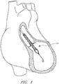
- Figure 1 illustrates one use of the disclosed catheter pump system.
- a distal portion of the pump which can include an impeller assembly 116A, is placed in the left ventricle (LV) of the heart to pump blood from the LV into the aorta.
- the pump can be used in this way to treat patients with a wide range of conditions, including cardiogenic shock, myocardial infarction, and other cardiac conditions, and also to support a patient during a procedure such as percutaneous coronary intervention.
- One convenient manner of placement of the distal portion of the pump in the heart is by percutaneous access and delivery using the Seldinger technique, or other methods familiar to cardiologists. These approaches enable the pump to be used in emergency medicine, a catheter lab and in other non-surgical settings.
- Modifications can also enable the pump 10 to support the right side of the heart.
- Example modifications that could be used for right side support include providing delivery features and/or shaping a distal portion that is to be placed through at least one heart valve from the venous side, such as is discussed in US 6,544,216 ; US 7,070,555 ; and US 2012-0203056A1 , all of which are hereby incorporated by reference herein in their entirety for all purposes.
- the catheter assembly 100A may correspond to the disposable portion of the heart pump systems described herein.
- the catheter assembly 100A may include the impeller assembly 116A near a distal portion of the catheter assembly 100A, an elongate body 174A extending proximally from the impeller assembly 116A, an infusion system 195 configured to supply infusate to the catheter assembly 100A, a motor assembly comprising a driven assembly 101 and a drive assembly 103, one or more conduits 302 (e.g., electrical and/or fluid conduits) extending proximally from the motor assembly, and an interface member 300 coupled at a proximal portion of the conduits 302.
- conduits 302 e.g., electrical and/or fluid conduits
- the impeller assembly 116A may be disposed at a distal portion of the catheter assembly 100A.
- the impeller assembly 116A can include an expandable cannula or housing and an impeller with one or more blades. As the impeller rotates, blood can be pumped proximally (or distally in some implementations) to function as a cardiac assist device.
- a priming apparatus 1400 can be disposed over the impeller assembly 116A. As explained herein with reference to Figures 7-8 , the priming apparatus 1400 can be configured to expedite a process of expelling air from the catheter assembly 100A before insertion of the operative device of the catheter assembly into the patient.
- the elongate body 174A extends proximally from the impeller assembly 116A to an infusion system 195 configured to allow infusate to enter the catheter assembly 100A and waste fluid to leave the catheter assembly 100A.
- a catheter body 120A (which also passes through the elongate body 174A) can extend proximally and couple to the driven assembly 101 of the motor assembly.
- the catheter body 120A can pass within the elongate body 174A, such that the elongate body 174A can axially translate relative to the catheter body 120A.
- Axial translation of the elongate body 174A relative to the catheter body 120A can enable the expansion and collapse of the impeller assembly 116A.
- the impeller assembly 116A coupled to a distal portion of the catheter body 120A, may expand into an expanded state by moving the elongate body 174A proximally relative to the impeller assembly 116A.
- the impeller assembly 116A may self-expand into the expanded state in some embodiments.
- the impeller assembly 116A is able to pump blood at high flow rates.
- the impeller assembly 116A may be compressed into a collapsed state by advancing a distal portion 170A of the elongate body 174A distally over the impeller assembly 116A to cause the impeller assembly 116A to collapse.
- the catheter body 120A can couple to the driven assembly 101 of the motor assembly.
- the driven assembly 101 can be configured to receive torque applied by the drive assembly 103, which is shown as being decoupled from the driven assembly 101 and the catheter assembly 100A in Figure 2 .
- the drive assembly 103 can be coupled to the driven assembly 101 by engaging a proximal portion of the driven assembly 101 with the drive assembly, e.g., by inserting the proximal portion of the driven assembly 101 into an aperture 105 of the drive assembly 103.
- a drive shaft can extend from the driven assembly 101 through the catheter body 120A to couple to an impeller shaft at or proximal to the impeller assembly 116A.
- the drive assembly 103 can electrically communicate with a controller in a console (see, e.g., Figures 3A-3B ), which can be configured to control the operation of the motor assembly and the infusion system 195 that supplies a flow of infusate in the catheter assembly 100A.
- the impeller of the impeller assembly 116A may thus be rotated remotely by the motor assembly during operation of the catheter pump in various embodiments.
- the motor assembly can be disposed outside the patient.
- the motor assembly is separate from the controller or console, e.g., to be placed closer to the patient. In other embodiments, the motor assembly is part of the controller. In still other embodiments, the motor assembly is miniaturized to be insertable into the patient. Such embodiments allow the drive shaft to be much shorter, e.g., shorter than the distance from the aortic valve to the aortic arch (about 5 cm or less).
- the motor assembly (e . g ., the drive assembly 103 and the driven assembly 101) is in electrical communication with the controller and console by way of the conduits 302, which may include electrical wires.
- the electrical wires may extend from the motor assembly proximally to the interface member 300.
- the controller in the console to electrically communicate with the motor assembly and/or other sensors in the catheter assembly 100A (such as pressure sensors, flow sensors, temperature sensors, bubble detectors, etc.), it can be advantageous to provide a reliable electrical connection between the interface member 300 and the console.
- the removable interface member 300 may include electrical components configured to couple to one or more electrical contacts (sometimes referred to herein as interconnections) in the console.
- the electrical connections may be achieved in a simple, user-friendly manner.
- the electrical connections may be made substantially at the same time, e . g ., substantially simultaneously, as fluid connections are made between the interface member 300 and console.
- the mechanical components rotatably supporting the impeller within the impeller assembly 116A permit high rotational speeds while controlling heat and particle generation that can come with high speeds.
- the infusion system 195 may deliver a cooling and lubricating solution to the distal portion of the catheter assembly 100A for these purposes. As shown in Figure 2 , the infusion system 195 may be in fluid communication with the interface member 300 by way of the conduits 302, which may also include fluid conduits or tubes. Because the catheter assembly 100A may be disposable and/or removable from a console, it can be important to securely couple interface member 300 to the console. Furthermore, it can be important to provide an easy-to-use interface such that users can easily complete fluid connections that remain secure during a treatment procedure.
- Maintaining security of the connection is important because the fluids and signals carried by the conduits 302 enable the impeller to operate in a continuous manner. Stoppage of the pump system may require the catheter assembly 100A to be removed from the patient and replaced in certain circumstances, which may be life-threatening or extremely inconvenient at a minimum.
- the catheter pump system When activated, the catheter pump system can effectively increase the flow of blood out of the heart and through the patient's vascular system.
- the pump can be configured to produce a maximum flow rate (e.g. low mm Hg) of greater than 4 Lpm, greater than 4.5 Lpm, greater than 5 Lpm, greater than 5.5 Lpm, greater than 6 Lpm, greater than 6.5 Lpm, greater than 7 Lpm, greater than 7.5 Lpm, greater than 8 Lpm, greater than 9 Lpm, or greater than 10 Lpm.
- a maximum flow rate e.g. low mm Hg
- the pump can be configured to produce an average flow rate at 62 mmHg pressure head of greater than 2 Lpm, greater than 2.5 Lpm, greater than 3 Lpm, greater than 3.5 Lpm, greater than 4 Lpm, greater than 4.25 Lpm, greater than 4.5 Lpm, greater than 5 Lpm, greater than 5.5 Lpm, or greater than 6 Lpm.
- Figure 3A is a three-dimensional perspective view of a fluid handling system 350 that includes a console 301 and the catheter assembly 100A of Figure 2 .
- the console 301 can provide electrical power, control signals, medical fluids (e . g ., saline) for infusion, and fluid waste extraction to the catheter assembly 100A by way of its interface with the interface member 300.
- medical fluids e . g ., saline
- the removable interface member 300 may be disposed at a proximal portion of the catheter assembly 100A and may be configured to couple to the console 301 at an interface region 303.
- the fluid handling system 350 can be configured to deliver fluids to and/or remove fluids from the catheter assembly 100A.
- saline and/or other medical solutions can lubricate and/or cool component between the motor assembly and the operative device.
- waste fluids can be removed from the catheter assembly 100A using the fluid handling system 350.
- the fluid handling system 350 can include a multilumen catheter body having a proximal end and a distal end. The catheter body can include one or more lumens through which medical solutions (e . g ., saline), waste fluids, and/or blood can flow.
- the console 301 may include one or more pump(s) configured to apply positive or negative pressure to the catheter assembly 100A when the catheter assembly 100A is coupled to the console 301 and engages the pump(s).
- the fluid handling system 350 may also be configured to provide electrical communication between the console 301 and the catheter assembly 100A.
- the console can include a controller (e.g., a processor) that is programmed to control and/or manage the operation of the motor assembly.
- the console 301 may also include electrical interfaces configured to supply power to the motor assembly and/or other components that are driven by electrical power when the interface member 300 is coupled to the console 301.
- one or more electrical or electronic sensors may be provided in the catheter assembly 100A and may electrically couple to the console 301 by way of the fluid handling system 350. The embodiments disclosed herein may thereby provide fluid and electrical connections between the catheter assembly 100A and the console 301.
- the fluid handling system 350 may provide a removable interface between the catheter assembly 100A and the console 301, which may include various components, including, e.g., one or more pump(s), processors (e.g., the controller), electrical interconnections, etc.
- a user may simply insert a distal portion of the interface member 300 (e.g., including a closure member) along the illustrated Z-direction into an aperture 304 of the interface region 303 until the pump(s) are engaged and the electrical connection(s) are formed.
- the insertion of the interface member along the Z-direction may engage the pump(s) and complete the electrical connection(s) substantially simultaneously.
- the interface member 300 may be secured to the console 301 by engaging a locking device between the interface region 303 and the interface member 300.
- a locking device is by rotating a portion of the interface member 300 relative to another portion of the interface member or relative to the console 301, as explained herein.
- rotation of an outermost structure (opposite the direction Z), sometimes referred to herein as a "cap" relative to the console may engage a locking mechanism configured to mechanically secure the interface member 300 to the console 301 to prevent the interface member 300 from being accidentally disengaged during a treatment procedure.
- the console 301 may also include a user interface 312, which may comprise a display device and/or a touch-screen display.
- the user may operate the percutaneous heart pump system by interacting with the user interface 312 to select, e.g., desired flow rates and other treatment parameters.
- the user may also monitor properties of the procedure on the user interface 312.
- Figure 3B is a three-dimensional perspective view of the interface region 303 of the console 301 shown in Figure 3A .
- the interface region 303 can include the aperture 304 configured to receive the distal portion of the interface member 303.
- the aperture 304 may include a generally circular cavity shaped and sized to receive a portion of the interface member 300.
- a bubble detector 308 (e.g., an optical sensor in some embodiments) can be positioned at a back wall of the aperture 304.
- the bubble detector 308 may include a recess portion defined by two walls sized and shaped to receive a segment of tubing.
- the bubble detector 308 may monitor the fluid to determine whether or not the fluid includes unwanted matter, e . g ., bubbles of air or other gas. In some embodiments, the bubble detector 308 may measure the amount (number or volume) of bubbles in the fluid passing though the tube segment. It should be appreciated that it can be important to detect bubbles in the treatment fluid to avoid inducing embolisms in the patient.
- the bubble detector 308 may electrically communicate with the controller in the console 301 and can indicate the amount of bubbles in the treatment fluid. The console 301, in turn, can alert the user if there are bubbles in the treatment fluid.
- the interface region 303 can also include one or more pumps, e . g ., peristaltic pumps in some embodiments.
- the peristaltic pumps can be used to pump fluid into or out of the catheter assembly 100A to deliver medical fluids and to remove waste fluids, respectively.
- Such pumps may employ one or more rollers 306 to control delivery of a fluid within a respective tube (see, e.g., pump tube segments 324a, 324b of Figure 4 ).
- the one or more pump rollers 306 can be housed within the console 301. As shown, two pump rollers 306 are mounted about their rotational axes (e.g., the Y-direction illustrated in Figure 3B ) at the back wall of the aperture 304.
- the pump rollers 306 can be rotated by a peristaltic pump motor within the console (not shown in Figures 3A-3B ). As explained in more detail herein with respect to Figure 4 below, the rollers 306 can engage pump tube segments 324a, 324b to pump fluid into or out of the catheter assembly 100A.
- the pump rollers 306 may be configured to be received within occlusion bed regions of the interface member 300 (see, e.g., occlusion beds 322a and 322b of Figure 4 ) to pump fluid through the catheter assembly 100A.
- An electrical interconnect 307 can also be provided in the back wall of the aperture 304.
- the electrical interconnect 307 can be configured to provide power to the motor assembly and/or electrical signals or instructions to control the operation of the motor assembly.
- the electrical interconnect 307 can also be configured to receive electrical signals indicative of sensor readings for monitoring pressure, flow rates, and/or temperature of one or more components in the catheter assembly 100A.
- a recessed channel 309 can extend from the bottom of the aperture 304 along the side to the lower edge of the console 301.
- the recessed channel 309 can be shaped and sized to receive one or more of the conduits 302 (e.g., electrical and/or fluid conduits) extending between the interface member 300 and the motor assembly. In one embodiment, all of the conduits 302 can be received within the channel 309 providing a flush side surface when the interface member 300 is disposed in the interface aperture 304.
- the interface region 303 can include a groove 313 sized and shaped to receive a locking mechanism (e . g ., a tab or flange projecting in the X direction) on the interface member 300.
- a locking mechanism e . g ., a tab or flange projecting in the X direction
- a disengaging member 305 includes a spring-loaded release mechanism 310 provided above the aperture 304 and a pin 311 that can be inserted into a hole in the interface member 300 (see, e.g., Figures 5A-5C and the accompanying disclosure below).
- the pin 311 can assist in releasing the interface member 300 relative to the console 301.
- the spring-loaded release mechanism 310 can be pressed to release the pin 311 and unlock the interface member 300 from the console 301.
- the spring-loaded release mechanism 310 can therefore act as a further safety mechanism to ensure that the cassette is not accidentally disengaged by the user.
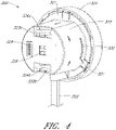
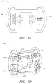
- Figure 4 is a three-dimensional perspective view of the interface member 300, according to one embodiment.
- the interface member 300 can comprise a body that is shaped and sized to fit into the interface region 303 of the console 301. As shown in Figure 4 , the interface member 300 can have a substantially circular profile, and is sometimes referred to as a puck.
- the interface member 300 can include an outer body 333 operably coupled to a manual interface 320, sometimes referred to as a cap.
- the manual interface 320 is generally palm-sized so that a user can receive it in their hand and operate it comfortably, e.g., with finger pressure on the outer rim of the cap.
- One or more occlusion beds can be formed or provided at the interface between the interface member 300 and the console 301, e.g., in or on the interface member 300.
- first and second occlusion beds 322a and 322b may be formed in the interface member 300.
- the occlusion beds 322a, 322b can include arcuate recessed regions formed in the interface member 300.
- the interface member 300 can further include first and second pump tube segments 324a, 324b positioned along the occlusion beds 322a, 322b formed in the interface member 300.
- the pump rollers 306 can engage with the interface member 300 and compress the tube segment(s) 324a, 324b against the occlusion bed(s) 322a, 322b, respectively.
- the pump motor(s) in the console 301 rotate the rollers 306, fluid flows into uncompressed portions of the tube segment(s) 324a, 324b and continues flowing throughout the catheter assembly 100A.
- the fluid may be pumped into or out of the catheter assembly 100A by way of the conduits 302 extending from the interface member 300 to the motor assembly and distally beyond the motor assembly.
- the body of the interface member 300 (e.g., the outer body 333 and/or an inner body, such as inner body 339 illustrated in Figures 5B-5C ) can be formed with precise tolerances (e . g ., molded from a unitary structure in some implementations) such that when the interface member 300 is inserted into the console 301, the pump rollers 306 precisely and automatically engage with the tube segments 324a, 324b and occlusion beds 322a, 322b to reliably occlude the tube segments 324a, 324b and pump fluids through the catheter assembly 100A.
- the pump in the console 301 can automatically engage the interface member 300.
- the gap between the rollers 306 and the occlusion beds 322a, 322b can be less than about two wall thicknesses of the tube segments 324a, 324b in some arrangements, such that the tubes 324a, 324b can be effectively occluded.
- the pump can be engaged by simply inserting the interface member 300 into the console 301. There is no need to separately activate the pump in some embodiments.
- the dimensions of the interface member 300 may be selected such that the occlusion bed(s) 322a, 322b automatically engages the respective pump rollers 306 upon insertion of the interface member 300 into the console 301.
- the interface member 300 and interface region 303 provide an easy-to-use, quick connection of the tubing segments to one or more respective rollers 306. Moreover, the components can be manufactured easily and cost-effectively because only certain components require tight tolerances and the interface of member 300 to region 303 is essentially self-aligning. The interface also eliminates any need to engage the pump through a second mechanism or operator step, streamlining operation of the heart pump and simplifying the engagement of the catheter assembly 100A to the console 301.
- the simplified engagement mechanisms disclosed herein can be advantageous because there is only a minimal applied force against the pole, which prevents the pole from rolling or tipping when the pump is engaged.
- the pump tube segments 324a, 324b can be mounted on the interface body 300 near or in the respective occlusion beds 322a, 322b. As illustrated, the first and second pump tube segments 324a, 324b can be configured to engage with the pump rollers 306 in the console 301, as explained above.
- the first and second pump tube segments 324a, 324b can have an arcuate shape (which may be pre-formed in various arrangements) that generally conforms to the curved shape of each respective occlusion bed 322a, 322b.
- the pump rollers 306 within the console 301 can thereby be positioned within the occlusion beds 322a, 322b to compress the tube segments 324a, 324b against the wall of the occlusion beds 322a, 322b.
- a bubble detector tube segment 326 can also be mounted in or on the interface member 300 and can be configured to engage with or be positioned adjacent to the bubble detector 308 illustrated in Figure 3B .
- the bubble detector tube segment 326 can be any suitable shape.
- the bubble detector tube segment can be substantially straight and can be sized and shaped to be received by the bubble detector 308 within the console 301.
- the bubble detector 308 (which may be an optical sensor) can be used to detect air bubbles in the treatment or lubricating fluid being supplied to the patient.
- the tube segments can be fluidly connected to the remainder of the catheter assembly 100A, including, e . g ., one or more lumens of the catheter body, by way of the conduits 302.
- the removable interface member 300 may allow fluid to be pumped into and out of the patient within a controlled system, e . g ., such that the fluids within the catheter assembly 100A can be pumped while maintaining a sterile environment for the fluids.
- the volume of medical solution into the catheter body can be equal to, or can exceed by a minimum amount, the volume of medical solution out of the catheter body to assure that blood does not enter a blood-free portion of the heart pump.
- one or more electrical contacts 328 can be provided in the interface member 300.
- the electrical contacts 328 can be any suitable electrical interface configured to transmit electrical signals between the console 301 and the catheter assembly 100A (e.g., the motor assembly and/or any suitable sensors).
- the electrical contacts 328 can be configured to electrically couple to the electrical interconnect 307 disposed in the console 301. Electrical control signals and/or power may be transmitted between the console 301 and the catheter assembly 100A by way of the electrical connection between the electrical contacts 328 and the electrical interconnect 307.
- the electrical connection between the electrical contacts 328 and the electrical interconnect 307 may be formed or completed when the interface member 300 is inserted into the interface region 303 of the console 301.
- the electrical connection between the electrical contacts 328 and the electrical interconnect 307 may be formed substantially simultaneously with the fluid connection ( e . g ., the engagement of the pump) when the interface member 300 is inserted into the interface region 303.
- the electrical connection can be formed by inserting electrical pins from the electrical contacts 328 into corresponding holes of the electrical interconnect 307 of the console 301, or vice versa.
- the manual interface 320 can be mechanically coupled to a proximal portion of the outer body 333 and may be configured to rotate relative to the outer body 333 in a constrained manner, as explained below relative to Figures 5A-5C .
- the outer body 333 can include one or more locking apertures 331 configured to receive locking tabs 332 that are configured to lock the manual interface 320 relative to the console 301.
- the outer body 333 may include a pin hole 321 sized and shaped to receive the pin 311 illustrated in Figure 3B to releasably couple the removable interface member 300 relative to the console 301.
- the configuration of the pump rollers, occlusion bed, and tubing can be modified depending on the application in accordance with the present inventions.
- the configuration may be modified to provide easier access for service and repair.
- the pump rollers may be disposed external to the console.
- the pump rollers and occlusion bed may be both disposed within the cassette.
- the console includes a mechanism to actuate the pump rollers in the cassette.
- the rollers may be fixed.
- the rollers may be configured to rotate, translate, or both.
- the rollers and/or the occlusion bed may be positioned on a base that is configured to move.
- the console-cassette interface can include a positive pressure interface to pump fluid (e.g., saline) into the patient's vasculature and a negative pressure interface to pump fluid (e . g ., waste fluid) out of the patient's vasculature.
- pump fluid e.g., saline
- negative pressure interface to pump fluid (e . g ., waste fluid) out of the patient's vasculature.
- the interface member 300 advantageously can be fully engaged with the console 301 by simply inserting it into a correspondingly shaped aperture 304 in the housing of the console 301.
- a locking mechanism in the interface member 300 can be provided for additional security, which can be particularly useful for patient transport and other more dynamic settings. For example, it is desirable to ensure that the catheter assembly 100A is secured to the console 301 during the entire procedure to ensure that the procedure is not disrupted due to accidental disengagement of the interface member 300 from the console 301.
- the locking mechanism can be disposed between the console 301 and the interface member 300 and can be configured to be engaged by a minimal movement of an actuator.
- the manual interface 320 can be provided to cause engagement of a locking device by a small rotational turn of the manual interface 320 relative to the console 301.
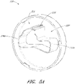
- Figure 5A is a three-dimensional perspective view of the manual interface 320.
- the manual interface 320 can include or be coupled with an internal cam 335.
- the cam 335 can include one or more protruding lobes, such as lobes 336a and 336b. Further, the cam 335 can include a recessed region 337 recessed inwardly relative to the lobes 336a, 336b.
- the cam 335 can also include a stepped region 338 which can enable the interface member 300 to be locked and unlocked relative to the console 301, as explained herein.
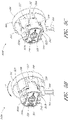
- Figure 5B is a three-dimensional perspective view of an interface member 300A in an unlocked configuration
- Figure 5C is a three-dimensional perspective view of an interface member 300B in a locked configuration.
- the interface members 300A, 300B of Figures 5B and 5C are illustrated without the outer body 333, which has been hidden in Figures 5B and 5C for purposes of illustration.
- the components of Figures 5B and 5C are the same as or similar to the components illustrated with respect to Figure 4 .
- the interface members 300A, 300B can include an inner body 339 that can be disposed within the outer body 333 shown in Figure 4 .
- the occlusion beds 322a, 322b can be formed in the inner body 339 of the interface member 300A, 300B, as shown in Figures 5B-5C ; however, in other arrangements, the occlusion beds 322a, 322b may be formed in the outer body 333 or other portions of the interface member 300A, 300B.
- an electrical component 340 can be disposed in a recess or other portion of the inner body 339. Additional details regarding the electrical component 340 are explained below with respect to Figures 6A-6B .
- the inner body 339 of the interface member 300A, 300B can further include a protrusion 330 that includes the tab 332 at a distal portion of the protrusion 330.
- the protrusion 330 can be disposed in or near the recess 337 of the cam 335 in the manual interface 320.
- the cam 335 may therefore not contact or apply a force against the protrusion 330 when the interface member 300A is in the unlocked configuration, as shown in Figure 5B .
- the interface member 300 can be locked into place by rotating the manual interface 320 relative to the inner body 339 and the console 301, e.g., rotated in the A-direction illustrated in Figure 5B .
- the internal cam 335 is also rotated within the interface member 300A, 300B.
- the lobes 336a, 336b of the cam 335 can engage with the one or more protrusions 330 of the inner body 339 and can push the protrusions 330 outwardly relative to the inner body 339.
- the tabs 332 may extend outwardly through the locking apertures 331 formed on the outer body 333.
- each of the tabs 332 can lock into the groove(s) 313 in the console 301 ( see Figure 3B ) to secure the interface member 300B to the console 301.
- the tab 332 in the unlocked position, can be substantially flush with the outer surface of the interface member 300A, and in the locked position, the tab 332 can extend through the locking aperture 331 and lock into the grooves 313 in the console 301.
- the protrusion 330 can be a cantilevered protrusion from the inner body 339. As mentioned above, it can be important to maintain tight tolerances between the occlusion beds 322a, 322b, which is also formed in the interface member, and the pump rollers 306 when the interface member 300 engages with the console 301. Because the occlusion beds 322a, 322b may be formed in the same body as the cantilevered protrusions 330, conventional manufacturing processes, such as molding processes, can be used to manufacture the interface member 300 (e.g., the outer body 333 and/or the inner body 339) according to precise dimensions.
- the protrusion(s) 330, tab(s) 332 and the occlusion bed(s) 322a, 322b can be made within tight dimensional tolerances, and the tab(s) 332 and/or protrusion(s) 330 can be positioned relative to the occlusion bed(s) 322a, 322b with very high precision such that when the interface member 300 is engaged with the console 301, the tube segments 324a, 324b are optimally occluded.
- the interface member 300 can be locked by rotating the manual interface 320 on the interface member 300, only minimal forces are applied to the console 301. This enhances the advantages of minimizing disruption of a mobile cart or IV pole to which the system may be coupled.
- the disengaging member 305 of the console 301 can be configured to disengage and unlock the interface member 300 from the console 301.
- the pin 311 may be spring-loaded such that when the interface member 300A is in the unlocked configuration, the pin 311 extends through the pin hole 321 of the outer body 333 but only contacts a side surface of one of the lobes 336b of the cam 335. Thus, in the unlocked configuration of the interface member 300A, the pin 311 may simply slide along the cam surface, permitting rotation of the manual interface 320 relative to the pin 311 and the console 301.
- the pin 311 can engage with the stepped region 338 of the internal cam 335, e.g., the spring-biased pin 311 can extend into the stepped region 338 or shoulder of the cam 335.
- the pin 311 prevents the cam 335 from rotating from the locked configuration to the unlocked configuration.
- a user can disengage the cassette by pressing the spring-loaded release mechanism 310 to release the spring and remove the pin 311 from the stepped region 338.
- the pin 311 can thereby be disengaged from the stepped region 338, and the internal cam 335 can rotate back into the unlocked position.
- the tab 332 can be withdrawn from the groove 313 in the console 301 to unlock the interface member 300.
- Figure 6A is a three-dimensional perspective view of a first side of the electrical component 340 illustrated in Figure 4 .
- Figure 6B is a three-dimensional perspective view of a second, opposite side of the electrical component 340 of Figure 6A .
- the electrical component 340 may be disposed in a recess of the interface member 300.
- the electrical component 340 can be any suitable electrical or electronic component, including, e.g., a printed circuit board (PCB) configured to provide an electrical interface between various components in the catheter assembly 100A and the console 301.
- the electrical component 340 can form an electrical interface between the interface member 300 and the console 301 to provide electrical communication between the console 301 and the catheter assembly 100A (such as the motor assembly and/or various sensors).
- the electrical component 340 of the interface member 300 can include the one or more electrical contacts 328 configured to mate with the corresponding electrical interconnect 307 in the console 301.
- the electrical contacts 328 and/or the electrical interconnect 307 can be, for example, nine-pin electrical interconnects, although any suitable interconnect can be used.
- the motor assembly that drives the operative device ( e . g ., impeller) of the catheter pump can be electrically connected to the interface member 300 by way of one or more electrical cables, e.g., the conduits 302.
- the console 301 can be coupled to a power source, which can drive the catheter pump motor assembly by way of the interface member's contacts 328 and the electrical conduits 302 connecting the interface member 300 to the motor assembly.
- the electrical component 340 can also include communications interconnects configured to relay electrical signals between the console 301 and the catheter pump motor assembly or other portions of the catheter assembly 100A.
- a controller within the console 301 (or interface member) can send instructions to the catheter pump motor assembly via the electrical component 340 between the console 301 and the interface member 300.
- the electrical component 340 can include interconnects for sensors (such as pressure or temperature sensors) within the catheter assembly 100A, including sensors at the operative device.
- the sensors may be used to measure a characteristic of the fluid in one or more of the tubes ( e . g ., saline pressure).
- the sensors may be used to measure an operational parameter of the system (e.g., ventricular or aortic pressure).
- the sensors may be provided as part of an adjunctive therapy.
- the electrical component 340 within the interface member 300 can be used to electrically couple the cable (and the motor assembly, sensors, etc.) with the corresponding interconnects 307 in the console 301.
- one or more internal connectors 346 and 348 on the second side of the electrical component 340 may provide electrical communication between the contacts 328 (configured to couple to the interconnects 307 of the console 301) and the catheter assembly 100.
- electrical cables e.g., the conduits 302
- the internal connectors 346, 348 may electrically communicate with the contacts 328 on the first side of the electrical component 340, which in turn communicate with the interconnects 307 of the console 301.
- the electrical component 340 is fluidly sealed to prevent the internal electronics from getting wet. This may be advantageous in wet and/or sterile environments. This may also advantageously protect the electronics in the event one of the fluid tubes leaks or bursts, which is a potential risk in high pressure applications.
- the electrical component 340 can include various electrical or electronic components mounted thereon.
- two pressure sensors 344a, 344b can be mounted on the electrical component 340 to detect the pressure in the pump tube segments 324a, 324b.
- the pressure sensors 344a, 344b may be used to monitor the flow of fluids in the tube segments 324a, 324b to confirm proper operation of the heart pump, for example, confirming a proper balance of medical solution into the catheter body and waste out of the catheter body.
- Various other components such as a processor, memory, or an Application-Specific Integrated Circuit (ASIC), can be provided on the circuit board.
- ASIC Application-Specific Integrated Circuit
- respective pressure sensor ASICs 345a, 345b can be coupled to the pressure sensors 344a, 344b to process the signals detected by the pressure sensors 344a, 344b.
- the processed signals may be transmitted from the ASICs 345a, 345b to the console 301 by way of internal traces (not shown) in the PCB and the contacts 328.
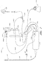
- an infusate system 1300 is illustrated in Figure 7 .
- the infusate system 1300 can be configured to supply treatment and/or lubricating fluids to the operative device of the catheter assembly (e . g ., an impeller assembly 116), and to remove waste fluid from the assembly.
- an elongate body 174 can be slidably disposed over a catheter body 120, such that there may be gaps or channels between the outer surface of the catheter body 120 and the inner surface of the elongate body 174. Such gaps or channels can contain air pockets harmful to the patient during a medical procedure.
- the lumen or lumens extending within the catheter body 120 also can contain air pockets harmful to the patient. Thus, it is desirable to expel air from both the lumens within catheter body 120 and the gaps or channels disposed between the elongate body 174 and the catheter body 120 before conducting a treatment procedure.
- the system 1300 of Figure 7 may be configured to supply fluid to the catheter assembly during treatment, to remove waste fluid during treatment, and/or to expel air from the elongate body 174, e.g., between the inner surface of the elongate body 174 and the outer surface of the catheter body 120 before treatment.
- an interface member 1313 (similar to or the same as the interface member 300 described herein, in some aspects) may be provided to connect various components of the catheter assembly, as discussed herein.
- An outer sheath tubing 1303a can extend from a fluid reservoir 1305 to a luer 102 configured to be coupled to an infusate device.
- the outer sheath tubing 1303a can be configured to deliver fluid to the outer sheath, e.g., the space between the elongate body 174 and the catheter body 120.
- the fluid reservoir 1305 may optionally include a pressure cuff to urge fluid through the outer sheath tubing 1303a. Pressure cuffs may be particularly useful in fluid delivery embodiments using gravity-induced fluid flow.
- the luer 102 can be configured to deliver infusate or other priming fluid to the elongate body 174 to expel air from the elongate body 174 as described herein in order to "prime" the system 1300.
- a pressure sensor 1309a which may be disposed on a motor housing 1314, can be coupled to the outer sheath tubing 1303a to measure the pressure of the infusate or priming fluid flowing through the outer sheath tubing 1303a and into the luer 102.
- the motor housing 1314 illustrated in Figure 7 may be the same as or similar to the motor assembly described above with reference to Figure 2 , for example, when the drive assembly 103 is coupled to the driven assembly 101.
- inner catheter tubing 1303b can extend between the motor housing 1314 and the fluid reservoir 1305, by way of a T-junction 1320.
- the inner catheter tubing 1303b can be configured to deliver fluid to the lumen or lumens within catheter body 120 during treatment and/or to expel air from the catheter 120 and prime the system 1300.
- a pumping mechanism 1306a such as a roller pump for example, can be provided along inner catheter tubing 1303b to assist in pumping the infusate or priming fluid through the system 1300.
- the roller pump can be a peristaltic pump in some arrangements.
- an air detector 1308 can be coupled to the inner catheter tubing 1303b and can be configured to detect any air or bubbles introduced into the system 1300.
- a pressure sensor 1309b can couple to inner catheter tubing 1303b to detect the pressure of the fluid within the tubing.
- a filter 1311 can be employed to remove debris and other undesirable particles from the infusate or priming fluid before the catheter body 120 is infused or primed with liquid.
- the air detector 1308, the pressure sensor 1309b, and the pumping mechanism 1306a can be coupled to the interface member 1313 described above (such as the interface member 300).
- One or more electrical lines 1315 can connect the motor housing 1314 with the cassette 1313.
- the electrical lines 1315 can provide electrical signals for energizing a motor or for powering the sensor 1309a or for other components.
- infusate or priming fluid can be introduced at the proximal end of the catheter assembly. The fluid can be driven distally to drive air out of the catheter body 120 to prime the system.
- a waste fluid line 1304 can fluidly connect the catheter body 120 with a waste reservoir 1310.
- a pressure sensor 1309c which may be disposed on or coupled to the interface member 1313, can measure the pressure of the fluid within the waste fluid line 1304.
- a pumping mechanism 1306b such as a roller pump, for example, can be coupled to the interface member 1313 and can pump the waste fluid through the waste fluid line 1304 to the waste reservoir 1310.
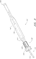
- Figure 8 is an enlarged view of the priming apparatus 1400 shown in Figure 2 .
- the priming apparatus 1400 may be disposed over the impeller assembly 116A near the distal end 170A of the elongate body 174A.
- the priming apparatus 1400 can be used in connection with a procedure to expel air from the impeller assembly 116A, e.g., any air that is trapped within the housing or that remains within the elongate body 174A near the distal end 170A.
- the priming procedure may be performed before the pump is inserted into the patient's vascular system, so that air bubbles are not allowed to enter and/or injure the patient.
- the priming apparatus 1400 can include a primer housing 1401 configured to be disposed around both the elongate body 174A and the impeller assembly 116A.
- a sealing cap 1406 can be applied to the proximal end 1402 of the primer housing 1401 to substantially seal the priming apparatus 1400 for priming, i.e. , so that air does not proximally enter the elongate body 174A and also so that priming fluid does not flow out of the proximal end of the housing 1401.
- the sealing cap 1406 can couple to the primer housing 1401 in any way known to a skilled artisan.
- the sealing cap 1406 is threaded onto the primer housing by way of a threaded connector 1405 located at the proximal end 1402 of the primer housing 1401.
- the sealing cap 1406 can include a sealing recess disposed at the distal end of the sealing cap 1406.
- the sealing recess can be configured to allow the elongate body 174A to pass through the sealing cap 1406.
- the priming operation can proceed by introducing fluid into the sealed priming apparatus 1400 to expel air from the impeller assembly 116A and the elongate body 174A.
- Fluid can be introduced into the priming apparatus 1400 in a variety of ways.
- fluid can be introduced distally through the elongate body 174A into the priming apparatus 1400.
- an inlet such as a luer, can optionally be formed on a side of the primer housing 1401 to allow for introduction of fluid into the priming apparatus 1400.
- a gas permeable membrane can be disposed on a distal end 1404 of the primer housing 1401.
- the gas permeable membrane can permit air to escape from the primer housing 1401 during priming.
- the priming apparatus 1400 also can advantageously be configured to collapse an expandable portion of the catheter assembly 100A.
- the primer housing 1401 can include a funnel 1415 where the inner diameter of the housing decreases from distal to proximal.
- the funnel may be gently curved such that relative proximal movement of the impeller housing causes the impeller housing to be collapsed by the funnel 1415.
- the distal end 170A of the elongate body 174A can be moved distally relative to the collapsed housing.
- the catheter assembly 100A can be removed from the priming housing 1400 before a percutaneous heart procedure is performed, e.g., before the pump is activated to pump blood.
- the embodiments disclosed herein may be implemented such that the total time for infusing the system is minimized or reduced.
- the time to fully infuse the system can be about six minutes or less.
- the infusate time can be less than 5 minutes, less than 4 minutes, or less than 3 minutes.
- the total time to infuse the system can be about 45 seconds or less. It should be appreciated that lower infusate times can be advantageous for use with cardiovascular patients.
- the heart pump is inserted in a less invasive manner, e.g., using techniques that can be employed in a catheter lab.
- the catheter assembly 100A Prior to insertion of the catheter assembly 100A of the heart pump, various techniques can be used to prepare the system for insertion.
- the catheter assembly 100A can be primed to remove gas that could be contained therein prior to any method being performed on the patient.
- This priming technique can be performed by placing a distal portion of the catheter assembly 100A in a priming vessel, such as the apparatus 1400. Thereafter, a media is delivered into the catheter assembly 100A under pressure to displace any potentially harmful matter, e.g., air or other gas, out of the catheter assembly 100A.
- the apparatus 1400 is filled with a biocompatible liquid such as saline.
- a biocompatible liquid such as saline is caused to flow distally through the catheter assembly 100 to displace air in any of the cavities formed therein, as discussed above.
- a pressure or flow rate for priming can be provided that is suitable for priming, e.g., a pressure or flow rate that is lower than the operational pressure or flow rate.
- the biocompatible liquid is pushed under positive pressure from the proximal end through the catheter assembly 100A until all gas is removed from voids therein.
- One technique for confirming that all gas has been removed is to observe the back-pressure or the current draw of the pump.
- the priming apparatus 1400 can be configured to permit gas to escape while preventing saline or other biocompatible liquid from escaping. As such, the back-pressure or current draw to maintain a pre-selected flow will change dramatically once all gas has been evacuated.
- the priming apparatus 1400 can include a source of negative pressure for drawing a biocompatible liquid into the proximal end of the catheter assembly 100A.
- Applying a negative pressure to the priming apparatus 1400 can have the advantage of permitting the catheter assembly 100A to be primed separate from the pumps that are used during operation of the heart pump.
- the priming can be done in parallel with other medical procedures on the patient by an operator that is not directly working on the patient.
- a positive pressure pump separate from the pump that operates the heart pump can be used to prime under positive pressure applied to the proximal end.
- Various priming methods may also be expedited by providing a separate inlet for faster filling of the enclosed volume of the priming apparatus 1400.
- a further aspect of certain methods of preparing the catheter assembly 100A for insertion into a patient can involve collapsing the impeller housing 116A.
- the collapsed state of the impeller housing 116A reduces the size, e.g., the crossing profile, of the distal end of the system. This enables a patient to have right, left or right and left side support through a small vessel that is close to the surface of the skin, e.g., using catheter lab-type procedures.
- the priming apparatus 1400 has a funnel configuration that has a large diameter at a distal end and a smaller diameter at a proximal end. The funnel gently transitions from the large to the small diameter.
- the impeller housing 116A can be collapsed by providing relative movement between the priming apparatus 1400 and the impeller housing 116A.
- the priming housing 1400 can be held in a fixed position, e . g ., by hand, and the catheter assembly 100A can be withdrawn until at least a portion of the impeller assembly 116A is disposed in the small diameter segment of the priming apparatus 1400.
- the elongate body 174A of the sheath assembly can be advanced over the collapsed impeller assembly 116A.
- the catheter assembly 100A is held still and the priming apparatus 1400 is slid distally over the impeller assembly 116A to cause the impeller assembly 116A to collapse. Thereafter, relative movement between the elongate body 174A and the impeller assembly 116A can position the distal end 170A of the elongate body 174A over the impeller assembly 116A after the catheter assembly 100A has been fully primed.
Applications Claiming Priority (4)
| Application Number | Priority Date | Filing Date | Title |
|---|---|---|---|
| US201361780656P | 2013-03-13 | 2013-03-13 | |
| EP21150599.5A EP3834876B1 (de) | 2013-03-13 | 2014-03-05 | Flüssigkeitsbehandlungssystem |
| EP14779928.2A EP2968718B1 (de) | 2013-03-13 | 2014-03-05 | Flüssigkeitsbehandlungssystem |
| PCT/US2014/020790 WO2014164136A1 (en) | 2013-03-13 | 2014-03-05 | Fluid handling system |
Related Parent Applications (2)
| Application Number | Title | Priority Date | Filing Date |
|---|---|---|---|
| EP21150599.5A Division EP3834876B1 (de) | 2013-03-13 | 2014-03-05 | Flüssigkeitsbehandlungssystem |
| EP14779928.2A Division EP2968718B1 (de) | 2013-03-13 | 2014-03-05 | Flüssigkeitsbehandlungssystem |
Publications (1)
| Publication Number | Publication Date |
|---|---|
| EP4122520A1 true EP4122520A1 (de) | 2023-01-25 |
Family
ID=51530250
Family Applications (3)
| Application Number | Title | Priority Date | Filing Date |
|---|---|---|---|
| EP21150599.5A Active EP3834876B1 (de) | 2013-03-13 | 2014-03-05 | Flüssigkeitsbehandlungssystem |
| EP14779928.2A Active EP2968718B1 (de) | 2013-03-13 | 2014-03-05 | Flüssigkeitsbehandlungssystem |
| EP22195112.2A Pending EP4122520A1 (de) | 2013-03-13 | 2014-03-05 | Flüssigkeitsbehandlungssystem |
Family Applications Before (2)
| Application Number | Title | Priority Date | Filing Date |
|---|---|---|---|
| EP21150599.5A Active EP3834876B1 (de) | 2013-03-13 | 2014-03-05 | Flüssigkeitsbehandlungssystem |
| EP14779928.2A Active EP2968718B1 (de) | 2013-03-13 | 2014-03-05 | Flüssigkeitsbehandlungssystem |
Country Status (4)
| Country | Link |
|---|---|
| US (5) | US9381288B2 (de) |
| EP (3) | EP3834876B1 (de) |
| JP (4) | JP6530367B2 (de) |
| WO (1) | WO2014164136A1 (de) |
Families Citing this family (49)
| Publication number | Priority date | Publication date | Assignee | Title |
|---|---|---|---|---|
| US7393181B2 (en) | 2004-09-17 | 2008-07-01 | The Penn State Research Foundation | Expandable impeller pump |
| WO2007112033A2 (en) | 2006-03-23 | 2007-10-04 | The Penn State Research Foundation | Heart assist device with expandable impeller pump |
| US9138518B2 (en) | 2011-01-06 | 2015-09-22 | Thoratec Corporation | Percutaneous heart pump |
| US9446179B2 (en) | 2012-05-14 | 2016-09-20 | Thoratec Corporation | Distal bearing support |
| US8721517B2 (en) | 2012-05-14 | 2014-05-13 | Thoratec Corporation | Impeller for catheter pump |
| DE102013008168A1 (de) | 2012-05-14 | 2013-11-14 | Thoratec Corporation | Laufrad für Katheterpumpe |
| US9872947B2 (en) | 2012-05-14 | 2018-01-23 | Tc1 Llc | Sheath system for catheter pump |
| US9327067B2 (en) | 2012-05-14 | 2016-05-03 | Thoratec Corporation | Impeller for catheter pump |
| EP4186557A1 (de) | 2012-07-03 | 2023-05-31 | Tc1 Llc | Motoranordnung für katheterpumpe |
| US9358329B2 (en) | 2012-07-03 | 2016-06-07 | Thoratec Corporation | Catheter pump |
| US9421311B2 (en) | 2012-07-03 | 2016-08-23 | Thoratec Corporation | Motor assembly for catheter pump |
| WO2014164136A1 (en) | 2013-03-13 | 2014-10-09 | Thoratec Corporation | Fluid handling system |
| US11077294B2 (en) | 2013-03-13 | 2021-08-03 | Tc1 Llc | Sheath assembly for catheter pump |
| US11033728B2 (en) | 2013-03-13 | 2021-06-15 | Tc1 Llc | Fluid handling system |
| EP3808390B1 (de) | 2013-03-15 | 2023-11-08 | Tc1 Llc | Katheterpumpenanordnung mit einem stator |
| US9308302B2 (en) | 2013-03-15 | 2016-04-12 | Thoratec Corporation | Catheter pump assembly including a stator |
| US10105475B2 (en) | 2014-04-15 | 2018-10-23 | Tc1 Llc | Catheter pump introducer systems and methods |
| US10583232B2 (en) | 2014-04-15 | 2020-03-10 | Tc1 Llc | Catheter pump with off-set motor position |
| EP3799918A1 (de) | 2014-04-15 | 2021-04-07 | Tc1 Llc | Sensoren für katheterpumpen |
| EP3131599B1 (de) | 2014-04-15 | 2019-02-20 | Tc1 Llc | Katheterpumpe mit zugangsports |
| EP3583973A1 (de) | 2014-08-18 | 2019-12-25 | Tc1 Llc | Führungsfunktionen für perkutane katheterpumpe |
| EP3045184B1 (de) * | 2015-01-13 | 2019-01-09 | ECP Entwicklungsgesellschaft mbH | Behälter für eine Herzpumpeneinrichtung sowie Verfahren zum Betrieb einer Herzpumpeneinrichtung |
| US9770543B2 (en) | 2015-01-22 | 2017-09-26 | Tc1 Llc | Reduced rotational mass motor assembly for catheter pump |
| US9675739B2 (en) | 2015-01-22 | 2017-06-13 | Tc1 Llc | Motor assembly with heat exchanger for catheter pump |
| WO2016118784A1 (en) | 2015-01-22 | 2016-07-28 | Thoratec Corporation | Attachment mechanisms for motor of catheter pump |
| CN111905230B (zh) * | 2015-01-22 | 2023-04-11 | Ecp发展有限责任公司 | 包括用于控制通过导管的流体流的阀的导管装置 |
| US9907890B2 (en) | 2015-04-16 | 2018-03-06 | Tc1 Llc | Catheter pump with positioning brace |
| EP3331596A4 (de) * | 2015-09-14 | 2019-04-03 | Thoratec Corporation | Flüssigkeitsbehandlungssystem |
| JP2019080594A (ja) * | 2016-03-18 | 2019-05-30 | テルモ株式会社 | カテーテルポンプおよび処置方法 |
| EP3804804A1 (de) | 2016-07-21 | 2021-04-14 | Tc1 Llc | Fluiddichtungen für katheterpumpenmotoranordnung |
| US11491322B2 (en) * | 2016-07-21 | 2022-11-08 | Tc1 Llc | Gas-filled chamber for catheter pump motor assembly |
| JP7383476B2 (ja) | 2016-10-25 | 2023-11-20 | マジェンタ・メディカル・リミテッド | 心室補助デバイス |
| DE102017102829A1 (de) | 2017-02-13 | 2018-08-16 | Cardiobridge Gmbh | Spülsystem |
| AU2018280236A1 (en) | 2017-06-07 | 2020-01-16 | Shifamed Holdings, Llc | Intravascular fluid movement devices, systems, and methods of use |
| US10090616B1 (en) * | 2017-06-27 | 2018-10-02 | Ethicon Llc | Surgical instrument handle assembly with feature to clean electrical contacts at modular shaft interface |
| EP3710076B1 (de) | 2017-11-13 | 2023-12-27 | Shifamed Holdings, LLC | Intravaskuläre fluidbewegungsvorrichtungen, systeme und verwendungsverfahren |
| JP7356431B2 (ja) | 2018-01-10 | 2023-10-04 | マジェンタ・メディカル・リミテッド | 心室補助デバイス |
| US10905808B2 (en) | 2018-01-10 | 2021-02-02 | Magenta Medical Ltd. | Drive cable for use with a blood pump |
| DE102018201030A1 (de) | 2018-01-24 | 2019-07-25 | Kardion Gmbh | Magnetkuppelelement mit magnetischer Lagerungsfunktion |
| US10722631B2 (en) | 2018-02-01 | 2020-07-28 | Shifamed Holdings, Llc | Intravascular blood pumps and methods of use and manufacture |
| WO2019212861A1 (en) * | 2018-04-30 | 2019-11-07 | Tc1 Llc | Improved blood pump connectors |
| DE102018211327A1 (de) | 2018-07-10 | 2020-01-16 | Kardion Gmbh | Laufrad für ein implantierbares, vaskuläres Unterstützungssystem |
| US11298525B2 (en) * | 2018-07-19 | 2022-04-12 | Abiomed, Inc. | Systems and methods for reducing leaks from a catheter |
| CN115137966A (zh) | 2019-01-24 | 2022-10-04 | 马真塔医药有限公司 | 心室辅助装置 |
| US11654275B2 (en) | 2019-07-22 | 2023-05-23 | Shifamed Holdings, Llc | Intravascular blood pumps with struts and methods of use and manufacture |
| US11724089B2 (en) | 2019-09-25 | 2023-08-15 | Shifamed Holdings, Llc | Intravascular blood pump systems and methods of use and control thereof |
| CN114945395A (zh) * | 2019-12-17 | 2022-08-26 | 康尔福盛303公司 | 用于输注装置的模块化电力和连接系统 |
| DE102020102474A1 (de) | 2020-01-31 | 2021-08-05 | Kardion Gmbh | Pumpe zum Fördern eines Fluids und Verfahren zum Herstellen einer Pumpe |
| WO2022120270A1 (en) * | 2020-12-04 | 2022-06-09 | Shifamed Holdings, Llc | Catheter blood pumps and external fluid control consoles |
Citations (17)
| Publication number | Priority date | Publication date | Assignee | Title |
|---|---|---|---|---|
| US5964694A (en) | 1997-04-02 | 1999-10-12 | Guidant Corporation | Method and apparatus for cardiac blood flow assistance |
| US6007478A (en) | 1997-11-13 | 1999-12-28 | Impella Cardiotechnik Aktiengesellschaft | Cannula having constant wall thickness with increasing distal flexibility and method of making |
| US6176848B1 (en) | 1996-04-04 | 2001-01-23 | Impella Cardiotechnik Gmbh | Intravascular blood pump |
| US6178922B1 (en) | 1997-04-15 | 2001-01-30 | Seefar Technologies, Inc. | Mastication article possessing microbe-inhibiting properties |
| US6544216B1 (en) | 1998-05-13 | 2003-04-08 | Impella Cardiotechnik Aktiengesellschaft | Intracardiac blood pump |
| US20040116862A1 (en) * | 2001-04-10 | 2004-06-17 | Claude Ray | Programmable cassette pump for injecting medicaments |
| US7022100B1 (en) | 1999-09-03 | 2006-04-04 | A-Med Systems, Inc. | Guidable intravascular blood pump and related methods |
| US7070555B2 (en) | 2000-08-18 | 2006-07-04 | Impella Cardiosystems Ag | Intracardiac blood pump |
| US7393181B2 (en) | 2004-09-17 | 2008-07-01 | The Penn State Research Foundation | Expandable impeller pump |
| US7841976B2 (en) | 2006-03-23 | 2010-11-30 | Thoratec Corporation | Heart assist device with expandable impeller pump |
| US20110004046A1 (en) | 2009-07-01 | 2011-01-06 | The Penn State Research Foundation | Blood pump with expandable cannula |
| US7998054B2 (en) | 1997-10-09 | 2011-08-16 | Thoratec Corporation | Implantable heart assist system and method of applying same |
| US20120172655A1 (en) | 2011-01-05 | 2012-07-05 | Campbell Robert L | Impeller housing for percutaneous heart pump |
| US20120178986A1 (en) | 2011-01-06 | 2012-07-12 | Campbell Robert L | Percutaneous heart pump |
| WO2012094534A2 (en) * | 2011-01-05 | 2012-07-12 | Thoratec Corporation | Percutaneous heart pump |
| US20120178985A1 (en) | 2011-01-06 | 2012-07-12 | Walters Daniel A | Percutaneous heart pump |
| US20120203056A1 (en) | 2010-05-26 | 2012-08-09 | Corbett Scott C | Anatomic fit of a percutaneous vad for right heart support |
Family Cites Families (495)
| Publication number | Priority date | Publication date | Assignee | Title |
|---|---|---|---|---|
| US1902418A (en) | 1931-11-02 | 1933-03-21 | Jensen Salsbery Lab Inc | Surgical instrument |
| US2356659A (en) | 1941-11-24 | 1944-08-22 | Aguiar Clovis De Paiva | Nozzle for duodenal pump tubes |
| US2649052A (en) | 1947-04-17 | 1953-08-18 | Marine Products Company | Rotary pump or motor |
| US2684035A (en) | 1947-10-02 | 1954-07-20 | Philip G Kemp | Fluid pump |
| US2664050A (en) | 1949-03-02 | 1953-12-29 | Gen Motors Corp | Domestic appliance |
| US2789511A (en) | 1953-05-25 | 1957-04-23 | Jabsco Pump Co | Flexible vane pump impeller |
| US2935068A (en) | 1955-08-04 | 1960-05-03 | Donaldson John Shearman | Surgical procedure and apparatus for use in carrying out the same |
| US2896926A (en) | 1956-01-10 | 1959-07-28 | Chapman Harold Eric | Device for mixing or treating fluids or free-flowing powders |
| US3080824A (en) | 1961-02-27 | 1963-03-12 | James A Boyd | Fluid moving device |
| US3455540A (en) | 1968-01-04 | 1969-07-15 | Emil G Marcmann | Stirring device |
| JPS4823295Y1 (de) | 1968-03-09 | 1973-07-06 | ||
| US3510229A (en) | 1968-07-23 | 1970-05-05 | Maytag Co | One-way pump |
| US3860968A (en) | 1969-11-20 | 1975-01-21 | Max Shapiro | Compact, implantable apparatus for pumping blood to sustain blood circulation in a living body |
| US3995617A (en) | 1972-05-31 | 1976-12-07 | Watkins David H | Heart assist method and catheter |
| CH591178A5 (de) | 1972-11-03 | 1977-09-15 | Anvar | |
| US3812812A (en) | 1973-06-25 | 1974-05-28 | M Hurwitz | Trolling propeller with self adjusting hydrodynamic spoilers |
| FR2267800A1 (en) | 1974-04-17 | 1975-11-14 | Anvar | Catheter insertion system - uses auxiliary fluid injected in catheter and forming propulsion jets |
| US4458366C1 (en) | 1975-05-09 | 2001-02-20 | David C Macgregor | Artificial implantable blood pump |
| LU77252A1 (de) | 1976-05-06 | 1977-08-22 | ||
| DE2624058C2 (de) | 1976-05-28 | 1984-11-15 | Franz Klaus-Union, 4630 Bochum | Permanentmagnetpumpe |
| US4066556A (en) * | 1976-10-28 | 1978-01-03 | Johnson & Johnson | Fluid filter and method of making same |
| US4135253A (en) | 1976-11-30 | 1979-01-23 | Medtronic, Inc. | Centrifugal blood pump for cardiac assist |
| US4129129A (en) | 1977-03-18 | 1978-12-12 | Sarns, Inc. | Venous return catheter and a method of using the same |
| US4143425A (en) | 1977-10-27 | 1979-03-13 | Runge Thomas M | Left atrial to descending thoracic aorta left ventricular assist device |
| USD264134S (en) | 1979-05-07 | 1982-04-27 | Stewart-Reiss Laboratories, Inc. | Disposable cassette for use in a peristaltic pump |
| GB2058231B (en) | 1979-09-07 | 1982-01-20 | Woodcoxon Eng International Lt | Variable pitch marine propellers |
| JPH0247496Y2 (de) | 1980-05-21 | 1990-12-13 | ||
| US4382199A (en) | 1980-11-06 | 1983-05-03 | Nu-Tech Industries, Inc. | Hydrodynamic bearing system for a brushless DC motor |
| DE3214397C2 (de) | 1982-04-20 | 1984-07-26 | Karl Dr. 6301 Pohlheim Aigner | Perfusions-Doppellumenkatheter |
| US4537561A (en) | 1983-02-24 | 1985-08-27 | Medical Technology, Ltd. | Peristaltic infusion pump and disposable cassette for use therewith |
| US4560375A (en) | 1983-06-30 | 1985-12-24 | Pudenz-Schulte Medical Research Corp. | Flow control valve |
| US4625712A (en) | 1983-09-28 | 1986-12-02 | Nimbus, Inc. | High-capacity intravascular blood pump utilizing percutaneous access |
| US4704121A (en) | 1983-09-28 | 1987-11-03 | Nimbus, Inc. | Anti-thrombogenic blood pump |
| US4673334A (en) | 1984-05-25 | 1987-06-16 | Isco, Inc. | Peristaltic pump |
| US4589822A (en) | 1984-07-09 | 1986-05-20 | Mici Limited Partnership Iv | Centrifugal blood pump with impeller |
| US4686982A (en) | 1985-06-19 | 1987-08-18 | John Nash | Spiral wire bearing for rotating wire drive catheter |
| US4769006A (en) | 1985-05-13 | 1988-09-06 | Kos Medical Technologies, Ltd. | Hydrodynamically propelled pacing catheter |
| US4655745A (en) | 1985-07-29 | 1987-04-07 | Corbett Joseph E | Ventricular catheter |
| US4728319A (en) | 1986-03-20 | 1988-03-01 | Helmut Masch | Intravascular catheter |
| US4696667A (en) | 1986-03-20 | 1987-09-29 | Helmut Masch | Intravascular catheter and method |
| US4819653A (en) | 1986-04-11 | 1989-04-11 | Lloyd A. Marks | Multi-function fluid communication control system |
| US4930341A (en) * | 1986-08-08 | 1990-06-05 | Scimed Life Systems, Inc. | Method of prepping a dilatation catheter |
| US4790315A (en) * | 1986-09-02 | 1988-12-13 | Advanced Cardiovascular Systems, Inc. | Perfusion dilatation catheter and method of manufacture |
| US4777951A (en) | 1986-09-19 | 1988-10-18 | Mansfield Scientific, Inc. | Procedure and catheter instrument for treating patients for aortic stenosis |
| US4753221A (en) | 1986-10-22 | 1988-06-28 | Intravascular Surgical Instruments, Inc. | Blood pumping catheter and method of use |
| US5195960A (en) * | 1987-04-27 | 1993-03-23 | Site Microsurgical Systems, Inc. | Disposable vacuum/peristaltic pump cassette system |
| US4902272A (en) | 1987-06-17 | 1990-02-20 | Abiomed Cardiovascular, Inc. | Intra-arterial cardiac support system |
| US4817586A (en) | 1987-11-24 | 1989-04-04 | Nimbus Medical, Inc. | Percutaneous bloom pump with mixed-flow output |
| US4846152A (en) | 1987-11-24 | 1989-07-11 | Nimbus Medical, Inc. | Single-stage axial flow blood pump |
| AU2807389A (en) | 1987-12-07 | 1989-07-05 | Nimbus Medical, Inc. | Inflow cannula for intravascular blood pumps |
| US4895557A (en) | 1987-12-07 | 1990-01-23 | Nimbus Medical, Inc. | Drive mechanism for powering intravascular blood pumps |
| US5061256A (en) | 1987-12-07 | 1991-10-29 | Johnson & Johnson | Inflow cannula for intravascular blood pumps |
| US4906229A (en) | 1988-05-03 | 1990-03-06 | Nimbus Medical, Inc. | High-frequency transvalvular axisymmetric blood pump |
| US5074756A (en) | 1988-05-17 | 1991-12-24 | Patient Solutions, Inc. | Infusion device with disposable elements |
| US5246347A (en) | 1988-05-17 | 1993-09-21 | Patients Solutions, Inc. | Infusion device with disposable elements |
| FR2632686B1 (de) | 1988-06-14 | 1993-07-16 | Thomson Brandt Armements | |
| US4908012A (en) | 1988-08-08 | 1990-03-13 | Nimbus Medical, Inc. | Chronic ventricular assist system |
| US4964864A (en) | 1988-09-27 | 1990-10-23 | American Biomed, Inc. | Heart assist pump |
| JPH0653161B2 (ja) | 1988-09-28 | 1994-07-20 | 東洋紡績株式会社 | 循環装置 |
| US4919647A (en) | 1988-10-13 | 1990-04-24 | Kensey Nash Corporation | Aortically located blood pumping catheter and method of use |
| US4957504A (en) | 1988-12-02 | 1990-09-18 | Chardack William M | Implantable blood pump |
| US5112292A (en) | 1989-01-09 | 1992-05-12 | American Biomed, Inc. | Helifoil pump |
| US4969865A (en) | 1989-01-09 | 1990-11-13 | American Biomed, Inc. | Helifoil pump |
| US4944722A (en) | 1989-02-23 | 1990-07-31 | Nimbus Medical, Inc. | Percutaneous axial flow blood pump |
| FR2644212B1 (fr) | 1989-03-13 | 1991-11-15 | Malbec Edouard | Cassette pour pompe peristaltique a tube deformable, et pompe peristaltique equipee d'une telle cassette |
| US5163900A (en) | 1989-03-16 | 1992-11-17 | Surgin Surgical Instrumentation, Inc. | Disposable cassette systems |
| US4976270A (en) | 1989-03-28 | 1990-12-11 | Vanderbilt University | Apparatus for continuously sampling plasma |
| US4995857A (en) | 1989-04-07 | 1991-02-26 | Arnold John R | Left ventricular assist device and method for temporary and permanent procedures |
| US5049134A (en) | 1989-05-08 | 1991-09-17 | The Cleveland Clinic Foundation | Sealless heart pump |
| US5045072A (en) | 1989-06-13 | 1991-09-03 | Cordis Corporation | Catheter having highly radiopaque, flexible tip |
| US5089016A (en) | 1989-06-15 | 1992-02-18 | Abiomed Cardiovascular, Inc. | Blood pump |
| US4955856A (en) | 1989-06-30 | 1990-09-11 | Phillips Steven J | Method and apparatus for installing a ventricular assist device cannulae |
| US4985014A (en) | 1989-07-11 | 1991-01-15 | Orejola Wilmo C | Ventricular venting loop |
| US5021048A (en) | 1989-08-04 | 1991-06-04 | Medtronic, Inc. | Blood pump drive system |
| US5147186A (en) | 1989-08-04 | 1992-09-15 | Bio Medicus, Inc. | Blood pump drive system |
| US5098256A (en) | 1989-11-21 | 1992-03-24 | The Cleveland Clinic Foundation | Viscous seal blood pump |
| GB2239675A (en) | 1989-12-05 | 1991-07-10 | Man Fai Shiu | Pump for pumping liquid |
| US5000177A (en) | 1990-01-29 | 1991-03-19 | Cardiac Pacemakers, Inc. | Bipolar lead adapter with resilient housing and rigid retainers for plug seals |
| US5163910A (en) | 1990-04-10 | 1992-11-17 | Mayo Foundation For Medical Education And Research | Intracatheter perfusion pump apparatus and method |
| US5092844A (en) | 1990-04-10 | 1992-03-03 | Mayo Foundation For Medical Education And Research | Intracatheter perfusion pump apparatus and method |
| US5106368A (en) | 1990-04-20 | 1992-04-21 | Cook Incorporated | Collapsible lumen catheter for extracorporeal treatment |
| US5211546A (en) | 1990-05-29 | 1993-05-18 | Nu-Tech Industries, Inc. | Axial flow blood pump with hydrodynamically suspended rotor |
| US5112200A (en) | 1990-05-29 | 1992-05-12 | Nu-Tech Industries, Inc. | Hydrodynamically suspended rotor axial flow blood pump |
| DE4020120A1 (de) | 1990-06-25 | 1991-01-31 | Klaus Prof Dr Ing Affeld | Medizinische vorrichtung zur erzeugung eines alternierenden volumenstroms fuer den antrieb von implantierbaren blutpumpen |
| CA2022019C (en) | 1990-07-26 | 1992-12-29 | Michael Black | Catheter |
| US5059174A (en) * | 1990-08-23 | 1991-10-22 | Vaillancourt Vincent L | Fluid infusion delivery system |
| US5190528A (en) | 1990-10-19 | 1993-03-02 | Boston University | Percutaneous transseptal left atrial cannulation system |
| US5171212A (en) | 1991-02-08 | 1992-12-15 | Minnesota Mining And Manufacturing Company | Blood pumping system with backflow warning |
| US5234407A (en) | 1991-03-06 | 1993-08-10 | Baxter International Inc. | Method and device for exchanging cardiovascular guide catheter while a previously inserted angioplasty guide wire remains in place |
| US5142155A (en) | 1991-03-11 | 1992-08-25 | Hewlett-Packard Company | Catheter tip fluorescence-quenching fiber optic pressure sensor |
| US5234416A (en) | 1991-06-06 | 1993-08-10 | Advanced Cardiovascular Systems, Inc. | Intravascular catheter with a nontraumatic distal tip |
| US5221270A (en) | 1991-06-28 | 1993-06-22 | Cook Incorporated | Soft tip guiding catheter |
| US5584803A (en) | 1991-07-16 | 1996-12-17 | Heartport, Inc. | System for cardiac procedures |
| US6027863A (en) | 1991-09-05 | 2000-02-22 | Intratherapeutics, Inc. | Method for manufacturing a tubular medical device |
| US5741429A (en) | 1991-09-05 | 1998-04-21 | Cardia Catheter Company | Flexible tubular device for use in medical applications |
| JP2713515B2 (ja) | 1991-09-17 | 1998-02-16 | 禎祐 山内 | カテーテル装置 |
| US5449342A (en) | 1991-09-30 | 1995-09-12 | Nippon Zeon Co., Ltd. | Apparatus for assisting blood circulation |
| US5201679A (en) | 1991-12-13 | 1993-04-13 | Attwood Corporation | Marine propeller with breakaway hub |
| US5267956A (en) | 1992-02-05 | 1993-12-07 | Alcon Surgical, Inc. | Surgical cassette |
| EP0633798B1 (de) | 1992-03-31 | 2003-05-07 | Boston Scientific Corporation | Blutgefässfilter |
| DE4222380A1 (de) | 1992-07-08 | 1994-01-13 | Ernst Peter Prof Dr M Strecker | In den Körper eines Patienten perkutan implantierbare Endoprothese |
| US5300112A (en) | 1992-07-14 | 1994-04-05 | Aai Corporation | Articulated heart pump |
| JP3399528B2 (ja) | 1992-07-30 | 2003-04-21 | コーブ カルディオバスキュラー, インコーポレイテッド | 渦巻き型血液ポンプ |
| US5458459A (en) | 1992-07-30 | 1995-10-17 | Haemonetics Corporation | Centrifugal blood pump with impeller blades forming a spin inducer |
| US5676651A (en) | 1992-08-06 | 1997-10-14 | Electric Boat Corporation | Surgically implantable pump arrangement and method for pumping body fluids |
| US5290227A (en) | 1992-08-06 | 1994-03-01 | Pasque Michael K | Method of implanting blood pump in ascending aorta or main pulmonary artery |
| US5312341A (en) | 1992-08-14 | 1994-05-17 | Wayne State University | Retaining apparatus and procedure for transseptal catheterization |
| SE501215C2 (sv) | 1992-09-02 | 1994-12-12 | Oeyvind Reitan | Kateterpump |
| US5344443A (en) | 1992-09-17 | 1994-09-06 | Rem Technologies, Inc. | Heart pump |
| JP3265650B2 (ja) | 1992-09-30 | 2002-03-11 | 日本ゼオン株式会社 | 血液循環補助装置 |
| US5376114A (en) | 1992-10-30 | 1994-12-27 | Jarvik; Robert | Cannula pumps for temporary cardiac support and methods of their application and use |
| US5393207A (en) | 1993-01-21 | 1995-02-28 | Nimbus, Inc. | Blood pump with disposable rotor assembly |
| US5643226A (en) | 1993-02-24 | 1997-07-01 | Minnesota Mining And Manufacturing | Low velocity aortic cannula |
| ES2114964T3 (es) | 1993-04-23 | 1998-06-16 | Schneider Europ Ag | Endoprotesis con una capa de recubrimiento de material elastico y metodo para aplicar la capa sobre la endoprotesis. |
| US5752932A (en) | 1993-04-29 | 1998-05-19 | Scimed Life Systems, Inc. | Intravascular catheter with a recoverable guide wire lumen and method of use |
| US5405341A (en) | 1993-06-03 | 1995-04-11 | Med-Pro Design, Inc. | Catheter with multiple lumens |
| WO1995010989A1 (en) | 1993-10-19 | 1995-04-27 | Scimed Life Systems, Inc. | Intravascular stent pump |
| US5397222A (en) | 1993-11-01 | 1995-03-14 | Moss; Richard | Reusable medical cassette for ambulatory medical infusion pumps |
| US5393197A (en) | 1993-11-09 | 1995-02-28 | Lemont Aircraft Corporation | Propulsive thrust ring system |
| US5527159A (en) | 1993-11-10 | 1996-06-18 | The United States Of America As Represented By The Administrator Of The National Aeronautics And Space Administration | Rotary blood pump |
| ES2077519B1 (es) | 1993-11-22 | 1996-07-01 | Fernandez De Lomana Euge Anaya | Cateter intraaortico para perfusion y conservacion renal. |
| US5437541A (en) | 1993-12-30 | 1995-08-01 | Vainrub; John | Blade for axial fan |
| EP0997115B1 (de) | 1994-04-01 | 2003-10-29 | Prograft Medical, Inc. | Selbstausdehnbarer Stent bzw. Stenttransplantat und Verfahren zu ihrer Vorbereitung |
| US5597377A (en) | 1994-05-06 | 1997-01-28 | Trustees Of Boston University | Coronary sinus reperfusion catheter |
| DK0751794T3 (da) | 1994-05-13 | 2003-11-03 | Abbott Lab | Engangskassette til væskeinfusionspumpekammer med en trykknap til strømningsstop |
| US5403292A (en) | 1994-05-18 | 1995-04-04 | Schneider (Usa) Inc. | Thin wall catheter having enhanced torqueability characteristics |
| US5601420A (en) | 1994-09-12 | 1997-02-11 | Ivac Medical Systems, Inc. | Interlock, latching, and retaining mechanism for an infusion pump |
| US5490763A (en) | 1994-09-15 | 1996-02-13 | Abrams; Andrew L. | Pump for shear sensitive fluids |
| AU4242996A (en) | 1994-11-23 | 1996-06-17 | Navarre Biomedical, Ltd. | Flexible catheter |
| US5613935A (en) | 1994-12-16 | 1997-03-25 | Jarvik; Robert | High reliability cardiac assist system |
| US6203528B1 (en) | 1995-03-06 | 2001-03-20 | Baxter International Inc. | Unitary molded elastomer conduit for use with a medical infusion pump |
| US5904668A (en) | 1995-03-06 | 1999-05-18 | Sabratek Corporation | Cassette for an infusion pump |
| US5588812A (en) | 1995-04-19 | 1996-12-31 | Nimbus, Inc. | Implantable electric axial-flow blood pump |
| US5707218A (en) | 1995-04-19 | 1998-01-13 | Nimbus, Inc. | Implantable electric axial-flow blood pump with blood cooled bearing |
| US5793974A (en) | 1995-06-30 | 1998-08-11 | Sun Microsystems, Inc. | Network navigation and viewing system for network management system |
| US6007479A (en) | 1996-07-08 | 1999-12-28 | H.D.S. Systems Ltd. | Heart assist system and method |
| US5702418A (en) | 1995-09-12 | 1997-12-30 | Boston Scientific Corporation | Stent delivery system |
| DE19535781C2 (de) | 1995-09-26 | 1999-11-11 | Fraunhofer Ges Forschung | Vorrichtung zur aktiven Strömungsunterstützung von Körperflüssigkeiten |
| US5776161A (en) | 1995-10-16 | 1998-07-07 | Instent, Inc. | Medical stents, apparatus and method for making same |
| US6287336B1 (en) | 1995-10-16 | 2001-09-11 | Medtronic, Inc. | Variable flexibility stent |
| AU7431396A (en) | 1995-10-26 | 1997-05-15 | Medisystems Technology Corporation | Pressure measurement in blood treatment |
| US5824070A (en) | 1995-10-30 | 1998-10-20 | Jarvik; Robert | Hybrid flow blood pump |
| US5911685A (en) | 1996-04-03 | 1999-06-15 | Guidant Corporation | Method and apparatus for cardiac blood flow assistance |
| DE19613565C1 (de) | 1996-04-04 | 1997-07-24 | Guenter Prof Dr Rau | Intravasale Blutpumpe |
| US5868703A (en) | 1996-04-10 | 1999-02-09 | Endoscopic Technologies, Inc. | Multichannel catheter |
| US5738649A (en) | 1996-04-16 | 1998-04-14 | Cardeon Corporation | Peripheral entry biventricular catheter system for providing access to the heart for cardiopulmonary surgery or for prolonged circulatory support of the heart |
| US5746709A (en) | 1996-04-25 | 1998-05-05 | Medtronic, Inc. | Intravascular pump and bypass assembly and method for using the same |
| US5814011A (en) | 1996-04-25 | 1998-09-29 | Medtronic, Inc. | Active intravascular lung |
| US6254359B1 (en) | 1996-05-10 | 2001-07-03 | The United States Of America As Represented By The Administrator Of The National Aeronautics And Space Administration | Method for providing a jewel bearing for supporting a pump rotor shaft |
| DE19622335C2 (de) | 1996-06-04 | 1999-03-18 | Voelker Wolfram Priv Doz Dr Me | Ballonkatheter |
| CA2206729A1 (en) | 1996-06-13 | 1997-12-13 | Nitinol Devices & Components, Inc. | A stent |
| US6015272A (en) | 1996-06-26 | 2000-01-18 | University Of Pittsburgh | Magnetically suspended miniature fluid pump and method of designing the same |
| US5741234A (en) | 1996-07-16 | 1998-04-21 | Aboul-Hosn; Walid Nagib | Anatomical cavity access sealing condit |
| DE19629614A1 (de) | 1996-07-23 | 1998-01-29 | Cardiotools Herzchirurgietechn | Linksherzassistpumpe |
| JP2807786B2 (ja) | 1996-07-26 | 1998-10-08 | 工業技術院長 | 人工心臓用ポンプ |
| US5779721A (en) | 1996-07-26 | 1998-07-14 | Kensey Nash Corporation | System and method of use for revascularizing stenotic bypass grafts and other blood vessels |
| US6245026B1 (en) | 1996-07-29 | 2001-06-12 | Farallon Medsystems, Inc. | Thermography catheter |
| FR2753235B1 (fr) | 1996-09-10 | 1998-12-04 | Conseilray Sa | Pompe peristaltique portable |
| CA2237203C (en) | 1996-09-10 | 2007-09-18 | Sulzer Electronics Ag | Rotary pump and method for operation thereof |
| US5851174A (en) | 1996-09-17 | 1998-12-22 | Robert Jarvik | Cardiac support device |
| US5730628A (en) | 1996-09-25 | 1998-03-24 | Pacesetter, Inc. | Multi-contact connector for an implantable medical device |
| JP3488349B2 (ja) * | 1996-09-27 | 2004-01-19 | テルモ株式会社 | カテーテル用プライミング器具およびプライミング器具を備えたカテーテル装置 |
| US5957941A (en) | 1996-09-27 | 1999-09-28 | Boston Scientific Corporation | Catheter system and drive assembly thereof |
| US6783328B2 (en) | 1996-09-30 | 2004-08-31 | Terumo Cardiovascular Systems Corporation | Method and apparatus for controlling fluid pumps |
| US5895557A (en) | 1996-10-03 | 1999-04-20 | Kimberly-Clark Worldwide, Inc. | Latex-saturated paper |
| US5965089A (en) | 1996-10-04 | 1999-10-12 | United States Surgical Corporation | Circulatory support system |
| US6071093A (en) | 1996-10-18 | 2000-06-06 | Abiomed, Inc. | Bearingless blood pump and electronic drive system |
| US5888242A (en) | 1996-11-01 | 1999-03-30 | Nimbus, Inc. | Speed control system for implanted blood pumps |
| US5776111A (en) | 1996-11-07 | 1998-07-07 | Medical Components, Inc. | Multiple catheter assembly |
| US5807311A (en) | 1996-11-29 | 1998-09-15 | Palestrant; Aubrey M. | Dialysis catheter having rigid and collapsible lumens and related method |
| US5859482A (en) | 1997-02-14 | 1999-01-12 | General Electric Company | Liquid cooled electric motor frame |
| AUPO902797A0 (en) | 1997-09-05 | 1997-10-02 | Cortronix Pty Ltd | A rotary blood pump with hydrodynamically suspended impeller |
| US6129704A (en) | 1997-06-12 | 2000-10-10 | Schneider (Usa) Inc. | Perfusion balloon catheter having a magnetically driven impeller |
| CA2291734A1 (en) | 1997-06-27 | 1999-01-07 | Merck Sharp & Dohme Limited | Substituted 3-(benzylamino)piperidine derivatives and their use as therapeutic agents |
| US6123725A (en) | 1997-07-11 | 2000-09-26 | A-Med Systems, Inc. | Single port cardiac support apparatus |
| US6709418B1 (en) | 1997-07-11 | 2004-03-23 | A-Med Systems, Inc. | Apparatus and methods for entering cavities of the body |
| US6395026B1 (en) | 1998-05-15 | 2002-05-28 | A-Med Systems, Inc. | Apparatus and methods for beating heart bypass surgery |
| US6532964B2 (en) | 1997-07-11 | 2003-03-18 | A-Med Systems, Inc. | Pulmonary and circulatory blood flow support devices and methods for heart surgery procedures |
| US6059760A (en) | 1997-08-14 | 2000-05-09 | Medtronic, Inc. | Cannula having reverse flow tip |
| US6250880B1 (en) | 1997-09-05 | 2001-06-26 | Ventrassist Pty. Ltd | Rotary pump with exclusively hydrodynamically suspended impeller |
| US6371935B1 (en) | 1999-01-22 | 2002-04-16 | Cardeon Corporation | Aortic catheter with flow divider and methods for preventing cerebral embolization |
| US6042606A (en) | 1997-09-29 | 2000-03-28 | Cook Incorporated | Radially expandable non-axially contracting surgical stent |
| CA2303818A1 (en) | 1997-09-30 | 1999-04-08 | Paul S. Freed | Cardiovascular support control system |
| US6387037B1 (en) | 1997-10-09 | 2002-05-14 | Orqis Medical Corporation | Implantable heart assist system and method of applying same |
| UA56262C2 (uk) | 1997-10-09 | 2003-05-15 | Орквіс Медікел Корпорейшн | Імплантовувана система підтримки серця |
| US6610004B2 (en) | 1997-10-09 | 2003-08-26 | Orqis Medical Corporation | Implantable heart assist system and method of applying same |
| US6234995B1 (en) | 1998-11-12 | 2001-05-22 | Advanced Interventional Technologies, Inc. | Apparatus and method for selectively isolating a proximal anastomosis site from blood in an aorta |
| US6422990B1 (en) | 1997-11-26 | 2002-07-23 | Vascor, Inc. | Blood pump flow rate control method and apparatus utilizing multiple sensors |
| US6056719A (en) | 1998-03-04 | 2000-05-02 | Scimed Life Systems, Inc. | Convertible catheter incorporating a collapsible lumen |
| DE29804046U1 (de) | 1998-03-07 | 1998-04-30 | Schmitz Rode Thomas Dipl Ing D | Perkutan implantierbare selbstentfaltbare Axialpumpe zur temporären Herzunterstützung |
| US6176822B1 (en) | 1998-03-31 | 2001-01-23 | Impella Cardiotechnik Gmbh | Intracardiac blood pump |
| US6086527A (en) | 1998-04-02 | 2000-07-11 | Scimed Life Systems, Inc. | System for treating congestive heart failure |
| US6190357B1 (en) | 1998-04-21 | 2001-02-20 | Cardiothoracic Systems, Inc. | Expandable cannula for performing cardiopulmonary bypass and method for using same |
| US6511492B1 (en) | 1998-05-01 | 2003-01-28 | Microvention, Inc. | Embolectomy catheters and methods for treating stroke and other small vessel thromboembolic disorders |
| US6508777B1 (en) | 1998-05-08 | 2003-01-21 | Cardeon Corporation | Circulatory support system and method of use for isolated segmental perfusion |
| US6162194A (en) | 1998-05-20 | 2000-12-19 | Apollo Camera, Llc | Surgical irrigation apparatus and methods for use |
| AU4690699A (en) | 1998-06-19 | 2000-01-05 | A-Med Systems, Inc. | Apparatus and methods for entering cavities of the body |
| US6135943A (en) | 1998-08-07 | 2000-10-24 | Cardiac Assist Technologies, Inc. | Non-invasive flow indicator for a rotary blood pump |
| US6634364B2 (en) | 2000-12-15 | 2003-10-21 | Cardiac Pacemakers, Inc. | Method of deploying a ventricular lead containing a hemostasis mechanism |
| US6554798B1 (en) | 1998-08-18 | 2003-04-29 | Medtronic Minimed, Inc. | External infusion device with remote programming, bolus estimator and/or vibration alarm capabilities |
| AU5694199A (en) | 1998-08-27 | 2000-03-21 | A-Med Systems, Inc. | Intravascular cannulation apparatus and methods of use |
| US5927956A (en) | 1998-09-01 | 1999-07-27 | Linvatec Corporation | Peristaltic pump tubing system with latching cassette |
| US6254564B1 (en) | 1998-09-10 | 2001-07-03 | Percardia, Inc. | Left ventricular conduit with blood vessel graft |
| US6086570A (en) | 1998-09-29 | 2000-07-11 | A-Med Systems, Inc. | Hemostasis valve with membranes having offset apertures |
| US6234960B1 (en) | 1998-09-30 | 2001-05-22 | A-Med Systems, Inc. | Heart stabilizer apparatus |
| US6641558B1 (en) | 1998-09-30 | 2003-11-04 | A-Med Systems, Inc. | Method and apparatus for preventing air embolisms |
| WO2000019097A1 (en) | 1998-09-30 | 2000-04-06 | A-Med Systems, Inc. | Blood pump system with magnetic cable drive |
| US6113536A (en) | 1998-09-30 | 2000-09-05 | A-Med Systems, Inc. | Device and method of attaching a blood pump and tubes to a surgical retractor |
| US6210133B1 (en) | 1998-09-30 | 2001-04-03 | A-Med Systems, Inc. | Blood pump with sterile motor housing |
| US6152704A (en) | 1998-09-30 | 2000-11-28 | A-Med Systems, Inc. | Blood pump with turbine drive |
| DE29821565U1 (de) | 1998-12-02 | 2000-06-15 | Impella Cardiotech Ag | Lagerlose Blutpumpe |
| US6926662B1 (en) | 1998-12-23 | 2005-08-09 | A-Med Systems, Inc. | Left and right side heart support |
| GB9828696D0 (en) | 1998-12-29 | 1999-02-17 | Houston J G | Blood-flow tubing |
| US6217541B1 (en) | 1999-01-19 | 2001-04-17 | Kriton Medical, Inc. | Blood pump using cross-flow principles |
| US7780628B1 (en) | 1999-01-11 | 2010-08-24 | Angiodynamics, Inc. | Apparatus and methods for treating congestive heart disease |
| US6749598B1 (en) | 1999-01-11 | 2004-06-15 | Flowmedica, Inc. | Apparatus and methods for treating congestive heart disease |
| US7329236B2 (en) | 1999-01-11 | 2008-02-12 | Flowmedica, Inc. | Intra-aortic renal drug delivery catheter |
| US7122019B1 (en) | 2000-11-28 | 2006-10-17 | Flowmedica Inc. | Intra-aortic renal drug delivery catheter |
| US6210397B1 (en) | 1999-01-13 | 2001-04-03 | A-Med Systems, Inc. | Sealing cannula device |
| US6018208A (en) | 1999-01-26 | 2000-01-25 | Nimbus, Inc. | Articulated motor stator assembly for a pump |
| US6186665B1 (en) | 1999-01-26 | 2001-02-13 | Nimbus, Inc. | Motor rotor bearing assembly for a blood pump |
| US6123659A (en) | 1999-01-26 | 2000-09-26 | Nimbus Inc. | Blood pump with profiled outflow region |
| US6245007B1 (en) | 1999-01-28 | 2001-06-12 | Terumo Cardiovascular Systems Corporation | Blood pump |
| DE19904975A1 (de) | 1999-02-06 | 2000-09-14 | Impella Cardiotech Ag | Vorrichtung zur intravasalen Herzklappenoperation |
| US6305962B1 (en) | 1999-02-16 | 2001-10-23 | Nimbus, Incorporated | Inline cable connector |
| US6210318B1 (en) | 1999-03-09 | 2001-04-03 | Abiomed, Inc. | Stented balloon pump system and method for using same |
| EP1034808A1 (de) | 1999-03-09 | 2000-09-13 | Paul Frederik Gründeman | Vorrichtung zur transventrikularen, mechanischen Herzunterstützung |
| US6106494A (en) | 1999-03-19 | 2000-08-22 | Stryker Corporation | Self-contained fluid management pump system for surgical procedures |
| US6287319B1 (en) | 1999-03-30 | 2001-09-11 | Amed Systems, Inc. | Cannula with balloon tip |
| US6295877B1 (en) | 1999-03-30 | 2001-10-02 | A-Med Systems, Inc. | Pressure sensing cannula |
| AUPP995999A0 (en) | 1999-04-23 | 1999-05-20 | University Of Technology, Sydney | Non-contact estimation and control system |
| JP4489219B2 (ja) | 1999-09-17 | 2010-06-23 | 株式会社カネカ | バルーンカテーテル用保護具 |
| WO2000069489A1 (en) | 1999-05-18 | 2000-11-23 | A-Med Systems, Inc. | Supplemental port for catheter perfusion of surgical site |
| US20050165269A9 (en) | 1999-06-18 | 2005-07-28 | Aboul-Hosn Walid N. | Cannulation system and related methods |
| US6190304B1 (en) | 1999-07-13 | 2001-02-20 | University Of North Texas Health Science Center At Fort Worth | Enhanced intra-aortic balloon assist device |
| US6247892B1 (en) | 1999-07-26 | 2001-06-19 | Impsa International Inc. | Continuous flow rotary pump |
| US6136025A (en) | 1999-07-27 | 2000-10-24 | Barbut; Denise R. | Endoscopic arterial pumps for treatment of cardiac insufficiency and venous pumps for right-sided cardiac support |
| US20040253129A1 (en) | 1999-08-31 | 2004-12-16 | Sorensen Gary P. | Liquid venting surgical cassette |
| US6293926B1 (en) | 1999-11-10 | 2001-09-25 | Alcon Universal Ltd. | Peristaltic pump and cassette |
| US20030225366A1 (en) | 1999-08-31 | 2003-12-04 | Morgan Michael D. | Liquid venting surgical cassette |
| US6962488B2 (en) | 1999-11-10 | 2005-11-08 | Alcon, Inc. | Surgical cassette having an aspiration pressure sensor |
| WO2001017581A2 (en) | 1999-09-03 | 2001-03-15 | A-Med Systems, Inc. | Guidable intravascular blood pump and related methods |
| US6454775B1 (en) | 1999-12-06 | 2002-09-24 | Bacchus Vascular Inc. | Systems and methods for clot disruption and retrieval |
| US7655016B2 (en) | 1999-09-17 | 2010-02-02 | Covidien | Mechanical pump for removal of fragmented matter and methods of manufacture and use |
| DE19947907A1 (de) | 1999-10-06 | 2001-04-19 | Thomas Wolffgram | Katheter für die kombinierte Untersuchung des linken Ventrikels sowie der rechten und der linken Koronararterien |
| DE19951607A1 (de) | 1999-10-26 | 2001-05-10 | Biotronik Mess & Therapieg | Stent mit geschlossener Struktur |
| US7758521B2 (en) | 1999-10-29 | 2010-07-20 | Medtronic, Inc. | Methods and systems for accessing the pericardial space |
| US20030205233A1 (en) | 1999-12-02 | 2003-11-06 | A-Med Systems, Inc. | Surgical drape and panel assembly |
| DE29921352U1 (de) | 1999-12-04 | 2001-04-12 | Impella Cardiotech Ag | Intravasale Blutpumpe |
| DE60107401T2 (de) | 2000-03-27 | 2005-11-24 | The Cleveland Clinic Foundation, Cleveland | Chronisches leistungssteuerungssystem für rotodynamische blutpumpe |
| US20010031981A1 (en) | 2000-03-31 | 2001-10-18 | Evans Michael A. | Method and device for locating guidewire and treating chronic total occlusions |
| DE10016422B4 (de) | 2000-04-01 | 2013-10-31 | Impella Cardiosystems Ag | Parakardiale Blutpumpe |
| AU5317301A (en) | 2000-04-05 | 2001-10-23 | Stx Medical Inc | Intralumenal material removal systems and methods |
| US6517528B1 (en) | 2000-04-13 | 2003-02-11 | Scimed Life Systems, Inc. | Magnetic catheter drive shaft clutch |
| US6413222B1 (en) | 2000-04-13 | 2002-07-02 | Boston Scientific Corporation | Catheter drive shaft clutch |
| JP4363746B2 (ja) | 2000-05-25 | 2009-11-11 | 株式会社東芝 | 永久磁石式リラクタンス型回転電機 |
| US6527699B1 (en) | 2000-06-02 | 2003-03-04 | Michael P. Goldowsky | Magnetic suspension blood pump |
| US6613008B2 (en) | 2000-06-13 | 2003-09-02 | A-Med Systems, Inc. | Integrated system for cardiopulmonary bypass and related methods |
| US20030018380A1 (en) | 2000-07-07 | 2003-01-23 | Craig Charles H. | Platinum enhanced alloy and intravascular or implantable medical devices manufactured therefrom |
| DE10043151A1 (de) | 2000-08-31 | 2002-03-28 | Peter Steinruecke | Knochenzement mit antimikrobieller Wirksamkeit |
| GB0024304D0 (en) | 2000-10-04 | 2000-11-15 | Mcgill Shane R | Food blending apparatus |
| CN1157545C (zh) | 2000-10-25 | 2004-07-14 | 李国坤 | 磁悬浮轴承 |
| DE10058528A1 (de) | 2000-11-24 | 2002-05-29 | Emhart Inc | Clipanordnung zum lösbaren Befestigen eines Gegenstandes an mindestens einer Leitung |
| DE10058669B4 (de) | 2000-11-25 | 2004-05-06 | Impella Cardiotechnik Ag | Mikromotor |
| DE10059714C1 (de) | 2000-12-01 | 2002-05-08 | Impella Cardiotech Ag | Intravasale Pumpe |
| DE10060275A1 (de) | 2000-12-05 | 2002-06-13 | Impella Cardiotech Ag | Verfahren zum Kalibrieren eines Drucksensors oder eines Flussensors an einer Rotationspumpe |
| US6468298B1 (en) | 2000-12-28 | 2002-10-22 | Advanced Cardiovascular Systems, Inc. | Gripping delivery system for self-expanding stents and method of using the same |
| US6901289B2 (en) | 2000-12-29 | 2005-05-31 | Medtronic, Inc. | System for providing electrical stimulation to a left chamber of a heart |
| US6858019B2 (en) | 2001-01-09 | 2005-02-22 | Rex Medical, L.P. | Dialysis catheter and methods of insertion |
| EP1229244A1 (de) | 2001-01-31 | 2002-08-07 | Precimedix S.A. | Okklusiondetektor für eine peristaltische Pumpe |
| WO2002070039A2 (en) | 2001-03-01 | 2002-09-12 | Three Arch Partners | Intravascular device for treatment of hypertension |
| US6673105B1 (en) | 2001-04-02 | 2004-01-06 | Advanced Cardiovascular Systems, Inc. | Metal prosthesis coated with expandable ePTFE |
| US6547519B2 (en) | 2001-04-13 | 2003-04-15 | Hewlett Packard Development Company, L.P. | Blower impeller apparatus with pivotable blades |
| US6494694B2 (en) | 2001-04-25 | 2002-12-17 | Abbott Laboratories | Disposable infusion cassette with low air bubble retention and improved valves |
| US6814713B2 (en) | 2001-04-25 | 2004-11-09 | A-Med Systems, Inc. | Systems for performing minimally invasive cardiac medical procedures |
| DE10123139B4 (de) | 2001-04-30 | 2005-08-11 | Berlin Heart Ag | Verfahren zur Regelung einer Unterstützungspumpe für Fluidfördersysteme mit pulsatilem Druck |
| US6517315B2 (en) | 2001-05-29 | 2003-02-11 | Hewlett-Packard Company | Enhanced performance fan with the use of winglets |
| US6887215B2 (en) | 2001-06-01 | 2005-05-03 | Boston Scientific Scimed, Inc. | Compressible ureteral stent for comfort |
| US20020188167A1 (en) | 2001-06-06 | 2002-12-12 | Anthony Viole | Multilumen catheter for minimizing limb ischemia |
| US6939373B2 (en) | 2003-08-20 | 2005-09-06 | Advanced Cardiovascular Systems, Inc. | Intravascular stent |
| WO2003015609A2 (en) | 2001-08-16 | 2003-02-27 | Apex Medical, Inc. | Physiological heart pump control |
| US6749584B2 (en) * | 2001-08-17 | 2004-06-15 | Reva Medical, Inc. | Balloon protector sleeve |
| US6692318B2 (en) | 2001-10-26 | 2004-02-17 | The Penn State Research Foundation | Mixed flow pump |
| TW500877B (en) | 2001-11-09 | 2002-09-01 | Ind Tech Res Inst | Thermolysis reaction actuating pump system |
| US6981942B2 (en) | 2001-11-19 | 2006-01-03 | University Of Medicine And Dentristy Of New Jersey | Temporary blood circulation assist device |
| DE10158146A1 (de) | 2001-11-28 | 2003-06-18 | Horn Gmbh & Co Kg | Selbstansaugende Hybridpumpe |
| US6776794B1 (en) | 2001-11-28 | 2004-08-17 | Advanced Cardiovascular Systems, Inc. | Stent pattern with mirror image |
| JP2005514085A (ja) * | 2001-12-20 | 2005-05-19 | ダブリュ アイ ティー アイ ピー コーポレーション | 1回使用の使い捨てカテーテルアセンブリを有するモジュラ温熱療法システムおよび関連する方法 |
| US6866805B2 (en) | 2001-12-27 | 2005-03-15 | Advanced Cardiovascular Systems, Inc. | Hybrid intravascular stent |
| US7241307B2 (en) * | 2001-12-31 | 2007-07-10 | Medcool, Inc. | Method and apparatus for managing temperature in a patient |
| EP1469770B1 (de) | 2002-01-08 | 2010-10-27 | Micromed Technology, Inc. | System zum nachweis von ventrikelkollaps |
| WO2003063951A1 (en) | 2002-01-29 | 2003-08-07 | Advanced Bionics Corporation | Lead assembly for implantable microstimulator |
| US7288111B1 (en) | 2002-03-26 | 2007-10-30 | Thoratec Corporation | Flexible stent and method of making the same |
| AU2003236497A1 (en) | 2002-06-11 | 2003-12-22 | Walid Aboul-Hosn | Expandable blood pump and related methods |
| US20060155158A1 (en) | 2002-06-11 | 2006-07-13 | Aboul-Hosn Walid N | Percutaneously introduced blood pump and related methods |
| US20030231959A1 (en) | 2002-06-12 | 2003-12-18 | William Hackett | Impeller assembly for centrifugal pumps |
| US7998190B2 (en) | 2002-06-17 | 2011-08-16 | California Institute Of Technology | Intravascular miniature stent pump |
| US7241257B1 (en) | 2002-06-28 | 2007-07-10 | Abbott Cardiovascular Systems, Inc. | Devices and methods to perform minimally invasive surgeries |
| US7267667B2 (en) | 2002-07-11 | 2007-09-11 | Boston Scientific Scimed, Inc. | Fluid management system for coronary intervention |
| US6949066B2 (en) | 2002-08-21 | 2005-09-27 | World Heart Corporation | Rotary blood pump diagnostics and cardiac output controller |
| EP1393762A1 (de) * | 2002-08-29 | 2004-03-03 | Precimedix S.A. | Peristaltische medizinische Pumpe |
| ITMI20021895A1 (it) | 2002-09-06 | 2004-03-07 | Gambro Lundia Ab | Organo di intercettazione di flusso. |
| US6817836B2 (en) | 2002-09-10 | 2004-11-16 | Miwatec Incorporated | Methods and apparatus for controlling a continuous flow rotary blood pump |
| US7284956B2 (en) | 2002-09-10 | 2007-10-23 | Miwatec Co., Ltd. | Methods and apparatus for controlling a continuous flow rotary blood pump |
| DE10244090A1 (de) | 2002-09-23 | 2004-04-01 | Ismatec S.A. | Schlauchkassette für eine peristaltische Pumpe |
| US6860713B2 (en) | 2002-11-27 | 2005-03-01 | Nidec Corporation | Fan with collapsible blades, redundant fan system, and related method |
| US6972956B2 (en) | 2003-01-16 | 2005-12-06 | Hewlett-Packard Development Company, L.P. | Collapsible fan and system and method incorporating same |
| US20040249442A1 (en) | 2003-02-26 | 2004-12-09 | Fleming James A. | Locking stent having multiple locking points |
| US20070255167A1 (en) | 2004-03-01 | 2007-11-01 | Wolfe Tory Medical, Inc. | Apparatus for monitoring intra-abdominal pressure |
| US7018182B2 (en) | 2003-03-13 | 2006-03-28 | Chf Solutions, Inc. | Self-loading peristaltic pump for extracorporeal blood circuit |
| US20080269846A1 (en) | 2003-03-14 | 2008-10-30 | Light Sciences Oncology, Inc. | Device for treatment of blood vessels using light |
| DE20304533U1 (de) | 2003-03-21 | 2004-08-05 | Impella Cardiosystems Ag | Einführvorrichtung zum Einführen eines Gegenstandes in ein Körpergefäß |
| US7238010B2 (en) | 2003-04-14 | 2007-07-03 | Stryker Corporation | Surgical irrigation pump and tool system |
| CA2428741A1 (en) | 2003-05-13 | 2004-11-13 | Cardianove Inc. | Dual inlet mixed-flow blood pump |
| ITMO20030201A1 (it) * | 2003-07-11 | 2005-01-12 | Hs Hospital Service Spa | Sistema di infusione di soluzioni farmacologiche |
| WO2005007223A2 (en) * | 2003-07-16 | 2005-01-27 | Sasha John | Programmable medical drug delivery systems and methods for delivery of multiple fluids and concentrations |
| DE10336902C5 (de) | 2003-08-08 | 2019-04-25 | Abiomed Europe Gmbh | Intrakardiale Pumpvorrichtung |
| US7229258B2 (en) | 2003-09-25 | 2007-06-12 | Medforte Research Foundation | Streamlined unobstructed one-pass axial-flow pump |
| US20050085683A1 (en) | 2003-10-15 | 2005-04-21 | Bolling Steven F. | Implantable heart assist system and method of applying same |
| US7037069B2 (en) | 2003-10-31 | 2006-05-02 | The Gorman-Rupp Co. | Impeller and wear plate |
| US20050113631A1 (en) | 2003-11-12 | 2005-05-26 | Bolling Steven F. | Cannulae having a redirecting tip |
| EP1690325A2 (de) | 2003-11-28 | 2006-08-16 | Health Equipment Denmark APS | Einrichtung zur medizinischen sicherung |
| US7763011B2 (en) | 2003-12-22 | 2010-07-27 | Boston Scientific Scimed, Inc. | Variable density braid stent |
| DE102004001594B4 (de) | 2004-01-09 | 2006-09-21 | Bio-Gate Ag | Wundauflage und Verfahren zu deren Herstellung |
| US7290929B2 (en) | 2004-02-09 | 2007-11-06 | Varian Medical Systems Technologies, Inc. | Mounting system for an X-ray tube |
| US7261205B2 (en) | 2004-02-12 | 2007-08-28 | Medtronic Vascular, Inc. | Packaged system including a protective housing for a treatment device carried on a catheter |
| EP1721077B1 (de) | 2004-03-04 | 2011-09-07 | Cole-Parmer Instrument Company | Schlauchpumpe |
| EP1734898A1 (de) | 2004-03-15 | 2006-12-27 | Medtronic Vascular, Inc. | Stent mit widerstandsfähigkeit gegen radiales zerdrücken |
| US7160243B2 (en) | 2004-03-25 | 2007-01-09 | Terumo Corporation | Method and system for controlling blood pump flow |
| US7172551B2 (en) | 2004-04-12 | 2007-02-06 | Scimed Life Systems, Inc. | Cyclical pressure coronary assist pump |
| US7942804B2 (en) | 2004-05-20 | 2011-05-17 | Cor-Med Vascular, Inc. | Replaceable expandable transmyocardial ventricular assist device |
| WO2005123158A1 (en) | 2004-06-10 | 2005-12-29 | Orqis Medical Corporation | Cannulae and system having reduced flow resistance |
| FR2871858B1 (fr) | 2004-06-22 | 2006-10-27 | Gilson Sas Soc Par Actions Sim | Pompe peristaltique comprenant une cassette amovible verrouillable |
| FR2871857B1 (fr) | 2004-06-22 | 2008-09-12 | Gilson Sas Soc Par Actions Sim | Cassette de pompe peristaltique comprenant un organe de reglage du pincement du tube |
| EP1789112B1 (de) | 2004-08-13 | 2010-09-29 | Delgado, Reynolds M., III | Gerät zur langzeitunterstützung eines linken ventrikels beim pumpen von blut |
| US20060058869A1 (en) | 2004-09-14 | 2006-03-16 | Vascular Architects, Inc., A Delaware Corporation | Coiled ladder stent |
| US7597662B2 (en) * | 2004-09-30 | 2009-10-06 | Boston Scientific Scimed, Inc. | Multi-fluid delivery system |
| ES2392443T3 (es) | 2004-10-05 | 2012-12-10 | Inovex Co., Ltd. | Uso de una solución acuosa que contiene coloide de platino para el tratamiento de síntomas psiquiátricos |
| DE102004049986A1 (de) | 2004-10-14 | 2006-04-20 | Impella Cardiosystems Gmbh | Intrakardiale Blutpumpe |
| US20060089521A1 (en) | 2004-10-21 | 2006-04-27 | Chang Sheldon S L | Rotor driven linear flow blood pump |
| KR101223820B1 (ko) | 2004-10-29 | 2013-01-17 | 제리아 신야쿠 고교 가부시키 가이샤 | 카르바졸 유도체, 그 용매화물, 또는 약학적으로 허용되는그 염 |
| DE102004054714A1 (de) | 2004-11-12 | 2006-05-24 | Impella Cardiosystems Gmbh | Faltbare intravasal einführbare Blutpumpe |
| US8419609B2 (en) | 2005-10-05 | 2013-04-16 | Heartware Inc. | Impeller for a rotary ventricular assist device |
| DE102005017546A1 (de) | 2005-04-16 | 2006-10-19 | Impella Cardiosystems Gmbh | Verfahren zur Steuerung einer Blutpumpe |
| CA2611313A1 (en) | 2005-06-06 | 2006-12-14 | The Cleveland Clinic Foundation | Blood pump |
| US7619560B2 (en) | 2005-06-08 | 2009-11-17 | Nxp B.V. | GPS processing arrangement |
| US20130209292A1 (en) | 2005-07-01 | 2013-08-15 | Doan Baykut | Axial flow blood pump with hollow rotor |
| US7878967B1 (en) | 2005-10-06 | 2011-02-01 | Sanjaya Khanal | Heart failure/hemodynamic device |
| DE102006008325B4 (de) | 2006-02-20 | 2013-09-12 | W.O.M. World Of Medicine Ag | Schlauchkassette für eine peristaltische Pumpe |
| US8348991B2 (en) | 2006-03-29 | 2013-01-08 | Boston Scientific Scimed, Inc. | Stent with overlap and high expansion |
| US20070248477A1 (en) | 2006-03-29 | 2007-10-25 | Alcon, Inc. | Cassette having elastomeric clamping ribs |
| US7955365B2 (en) | 2006-04-07 | 2011-06-07 | Medtronic Vascular, Inc. | Closed loop catheter photopolymerization system and method of treating a vascular condition |
| US7942844B2 (en) | 2006-04-28 | 2011-05-17 | Medtronic Minimed, Inc. | Remote monitoring for networked fluid infusion systems |
| US7914436B1 (en) | 2006-06-12 | 2011-03-29 | Abiomed, Inc. | Method and apparatus for pumping blood |
| US9314263B2 (en) | 2006-06-30 | 2016-04-19 | Atheromed, Inc. | Atherectomy devices, systems, and methods |
| US20090018566A1 (en) | 2006-06-30 | 2009-01-15 | Artheromed, Inc. | Atherectomy devices, systems, and methods |
| US20080004645A1 (en) | 2006-06-30 | 2008-01-03 | Atheromed, Inc. | Atherectomy devices and methods |
| US8236044B2 (en) | 2006-06-30 | 2012-08-07 | Boston Scientific Scimed, Inc. | Stent design with variable expansion columns along circumference |
| US9492192B2 (en) | 2006-06-30 | 2016-11-15 | Atheromed, Inc. | Atherectomy devices, systems, and methods |
| WO2008027869A2 (en) | 2006-08-30 | 2008-03-06 | Circulite, Inc. | Devices, methods and systems for establishing supplemental blood flow in the circulatory system |
| WO2008034068A2 (en) | 2006-09-14 | 2008-03-20 | Circulite, Inc. | Intravascular blood pump and catheter |
| AU2007303132B2 (en) | 2006-10-04 | 2013-03-28 | Boston Scientific Limited | Interventional catheters |
| US9622888B2 (en) | 2006-11-16 | 2017-04-18 | W. L. Gore & Associates, Inc. | Stent having flexibly connected adjacent stent elements |
| US20140163664A1 (en) | 2006-11-21 | 2014-06-12 | David S. Goldsmith | Integrated system for the ballistic and nonballistic infixion and retrieval of implants with or without drug targeting |
| US20100286791A1 (en) | 2006-11-21 | 2010-11-11 | Goldsmith David S | Integrated system for the ballistic and nonballistic infixion and retrieval of implants |
| US20080132748A1 (en) | 2006-12-01 | 2008-06-05 | Medical Value Partners, Llc | Method for Deployment of a Medical Device |
| US20080167679A1 (en) | 2007-01-06 | 2008-07-10 | Papp John E | Cage and Sleeve Assembly for a Filtering Device |
| US7633193B2 (en) | 2007-01-17 | 2009-12-15 | Honeywell International Inc. | Thermal and secondary flow management of electrically driven compressors |
| US7722568B2 (en) | 2007-01-29 | 2010-05-25 | Onset Medical Corporation | Expandable intra-aortic balloon pump sheath |
| AU2008219653B2 (en) | 2007-02-26 | 2014-01-16 | Heartware, Inc. | Intravascular ventricular assist device |
| AT504990B1 (de) | 2007-02-27 | 2008-12-15 | Miracor Medizintechnik Handels | Katheter zur unterstützung der leistung eines herzens |
| DE102007012817A1 (de) | 2007-03-16 | 2008-09-18 | Mwf Consult Ltd. | Vorrichtung zur Unterstützung des Herzens und des Kreislaufs |
| DE102007014224A1 (de) | 2007-03-24 | 2008-09-25 | Abiomed Europe Gmbh | Blutpumpe mit Mikromotor |
| WO2008139459A1 (en) | 2007-05-11 | 2008-11-20 | Medingo Ltd. | Methods and apparatus for monitoring rotation of an infusion pump driving mechanism |
| US7828710B2 (en) | 2007-06-05 | 2010-11-09 | Medical Value Partners, Llc | Apparatus comprising a drive cable for a medical device |
| EP2173408A1 (de) | 2007-06-27 | 2010-04-14 | Medingo Ltd. | Schlauch für eine flüssigkeitsabgabevorrichtung |
| JP2007252960A (ja) * | 2007-06-29 | 2007-10-04 | Kaneka Corp | バルーンカテーテル用保護具 |
| EP2016961B1 (de) | 2007-07-18 | 2010-02-17 | Surgery in Motion Ltd. | Vorrichtung zur Unterstützung bei der Herzbehandlung |
| ES2400307T3 (es) | 2007-07-19 | 2013-04-09 | Circulite, Inc. | Cánula para implantación en cámara cardiaca y sistemas y métodos relacionados |
| US20090053085A1 (en) | 2007-08-24 | 2009-02-26 | Thompson Loren M | Peristalitic pump assembly and method for attaching a cassette thereto |
| US8079948B2 (en) | 2007-08-29 | 2011-12-20 | NuCardia, Inc. | Article comprising an impeller |
| US8083503B2 (en) | 2007-09-27 | 2011-12-27 | Curlin Medical Inc. | Peristaltic pump assembly and regulator therefor |
| US7934912B2 (en) | 2007-09-27 | 2011-05-03 | Curlin Medical Inc | Peristaltic pump assembly with cassette and mounting pin arrangement |
| US8062008B2 (en) | 2007-09-27 | 2011-11-22 | Curlin Medical Inc. | Peristaltic pump and removable cassette therefor |
| EP2047873B1 (de) | 2007-10-08 | 2010-12-15 | Ais Gmbh Aachen Innovative Solutions | Katheter-Vorrichtung |
| US8489190B2 (en) | 2007-10-08 | 2013-07-16 | Ais Gmbh Aachen Innovative Solutions | Catheter device |
| DE502007005015C5 (de) | 2007-10-08 | 2020-02-20 | Ais Gmbh Aachen Innovative Solutions | Katheter-Vorrichtung |
| US8439859B2 (en) | 2007-10-08 | 2013-05-14 | Ais Gmbh Aachen Innovative Solutions | Catheter device |
| WO2009048600A2 (en) | 2007-10-09 | 2009-04-16 | Glenn Bradley J | Enhanced stability implantable medical device |
| US20090099638A1 (en) | 2007-10-11 | 2009-04-16 | Med Institute, Inc. | Motorized deployment system |
| US8052399B2 (en) | 2007-10-18 | 2011-11-08 | Cole-Parmer Instrument Company | Peristaltic pump |
| US8070762B2 (en) | 2007-10-22 | 2011-12-06 | Atheromed Inc. | Atherectomy devices and methods |
| US8343029B2 (en) | 2007-10-24 | 2013-01-01 | Circulite, Inc. | Transseptal cannula, tip, delivery system, and method |
| US9199020B2 (en) | 2007-11-01 | 2015-12-01 | Abiomed, Inc. | Purge-free miniature rotary pump |
| EP2712547B1 (de) * | 2007-11-26 | 2015-09-30 | C. R. Bard, Inc. | Integriertes System zur intravaskulären Platzierung eines Katheters |
| JP5112520B2 (ja) | 2007-12-07 | 2013-01-09 | ヌカーディア インク. | 医療装置 |
| US20110054592A1 (en) | 2007-12-12 | 2011-03-03 | Cornova, Inc. | Flexible expandable stent and methods of deployment |
| US20130053693A1 (en) * | 2007-12-21 | 2013-02-28 | Indian Wells Medical, Inc. | Method and apparatus for prevention of catheter air intake |
| US7935102B2 (en) | 2007-12-21 | 2011-05-03 | Indian Wells Medical, Inc | Method and apparatus for prevention of catheter air intake |
| US8235943B2 (en) | 2007-12-21 | 2012-08-07 | Indian Wells Medical, Inc. | Method and apparatus for prevention of catheter air intake |
| JP4681625B2 (ja) | 2008-02-22 | 2011-05-11 | 三菱重工業株式会社 | 血液ポンプおよびポンプユニット |
| US8236040B2 (en) | 2008-04-11 | 2012-08-07 | Endologix, Inc. | Bifurcated graft deployment systems and methods |
| EP2127864A1 (de) | 2008-05-30 | 2009-12-02 | Jacob Zeilon AB | Mehrschichtige Struktur, Produkt mit dieser Struktur und Verfahren zur Herstellung dieser Struktur |
| US8496652B2 (en) * | 2008-06-06 | 2013-07-30 | Ethicon, Inc. | Balloon catheter systems and methods for treating uterine disorders |
| ES2449221T3 (es) | 2008-06-23 | 2014-03-18 | Cardiobridge Gmbh | Bomba de catéter para apoyo circulatorio |
| US20100004595A1 (en) * | 2008-07-01 | 2010-01-07 | Ethicon, Inc. | Balloon catheter systems for treating uterine disorders having fluid line de-gassing assemblies and methods therefor |
| US8257312B2 (en) | 2008-07-30 | 2012-09-04 | Medtronic, Inc. | Integrated slitter for medical instrument inserter |
| US8465456B2 (en) | 2008-07-31 | 2013-06-18 | Boston Scientific Scimed, Inc. | Extendable aspiration catheter |
| JP5298699B2 (ja) * | 2008-08-20 | 2013-09-25 | セイコーエプソン株式会社 | 制御ユニット、チューブユニット、マイクロポンプ |
| US8435212B2 (en) | 2008-09-15 | 2013-05-07 | Leonid Grigorov | Methods and devices for programmable delivery of microdoses of liquid drugs and other fluids |
| AU2009296514B2 (en) | 2008-09-26 | 2014-04-10 | Carnegie Mellon University | Magnetically-levitated blood pump with optimization method enabling miniaturization |
| CA2739899C (en) | 2008-10-06 | 2017-05-16 | Indiana University Research And Technology Corporation | Apparatus for active or passive assistance in the circulatory system |
| US20100127871A1 (en) | 2008-11-26 | 2010-05-27 | Pontin Srl | System and method for verification of shipped products using rfid tags |
| EP2194278A1 (de) | 2008-12-05 | 2010-06-09 | ECP Entwicklungsgesellschaft mbH | Fluidpumpe mit einem rotor |
| US7993259B2 (en) | 2009-01-23 | 2011-08-09 | Wei-Chang Kang | Percutaneous intra-aortic ventricular assist device |
| EP2216059A1 (de) | 2009-02-04 | 2010-08-11 | ECP Entwicklungsgesellschaft mbH | Kathetereinrichtung mit einem Katheter und einer Betätigungseinrichtung |
| US20110066047A1 (en) | 2009-03-17 | 2011-03-17 | Claude Belleville | Eccentric pressure catheter with guidewire compatibility |
| EP2248544A1 (de) | 2009-05-05 | 2010-11-10 | ECP Entwicklungsgesellschaft mbH | Im Durchmesser veränderbare Fluidpumpe, insbesondere für die medizinische Verwendung |
| WO2010133567A1 (en) | 2009-05-18 | 2010-11-25 | Cardiobridge Gmbh | Catheter pump |
| JP2011000620A (ja) | 2009-06-19 | 2011-01-06 | Showa Denko Kk | パイプと被接合部材との接合方法 |
| EP2266640A1 (de) | 2009-06-25 | 2010-12-29 | ECP Entwicklungsgesellschaft mbH | Komprimierbares und expandierbares Schaufelblatt für eine Fluidpumpe |
| US8382818B2 (en) | 2009-07-02 | 2013-02-26 | Tryton Medical, Inc. | Ostium support for treating vascular bifurcations |
| CA2767668C (en) | 2009-07-15 | 2017-03-07 | Fresenius Medical Care Holdings, Inc. | Medical fluid cassettes and related systems and methods |
| EP2282070B1 (de) | 2009-08-06 | 2012-10-17 | ECP Entwicklungsgesellschaft mbH | Kathetereinrichtung mit einer Ankopplungseinrichtung für eine Antriebseinrichtung |
| US9072540B2 (en) | 2009-08-12 | 2015-07-07 | Boston Scientific Limited | Adaptive tubing cassettes for use in connection with interventional catheter assemblies |
| US8388582B2 (en) * | 2009-08-12 | 2013-03-05 | Medrad, Inc. | Systems and methods for operating interventional catheters using a common operating console and adaptive interface components |
| AU2010286587B2 (en) | 2009-08-27 | 2013-10-17 | Medtronic Inc. | Transcatheter valve delivery systems and methods |
| AU2010292247B2 (en) | 2009-09-09 | 2015-05-14 | Abiomed, Inc. | Method for simultaneously delivering fluid to a dual lumen catheter with a single fluid source |
| EP3441616B1 (de) | 2009-09-22 | 2023-04-19 | ECP Entwicklungsgesellschaft mbH | Komprimierbarer rotor für eine fluidpumpe |
| EP2298372A1 (de) | 2009-09-22 | 2011-03-23 | ECP Entwicklungsgesellschaft mbH | Rotor für eine Axialpumpe zur Förderung eines Fluids |
| EP2298373A1 (de) | 2009-09-22 | 2011-03-23 | ECP Entwicklungsgesellschaft mbH | Fluidpumpe mit wenigstens einem Schaufelblatt und einer Stützeinrichtung |
| EP2298371A1 (de) | 2009-09-22 | 2011-03-23 | ECP Entwicklungsgesellschaft mbH | Funktionselement, insbesondere Fluidpumpe, mit einem Gehäuse und einem Förderelement |
| DE102009047845A1 (de) | 2009-09-30 | 2011-03-31 | Abiomed Europe Gmbh | Herzunterstützungssystem |
| EP2314331B1 (de) | 2009-10-23 | 2013-12-11 | ECP Entwicklungsgesellschaft mbH | Katheterpumpenanordnung und flexible Wellenanordnung mit einer Seele |
| US8690749B1 (en) | 2009-11-02 | 2014-04-08 | Anthony Nunez | Wireless compressible heart pump |
| US8142400B2 (en) | 2009-12-22 | 2012-03-27 | Q-Core Medical Ltd. | Peristaltic pump with bi-directional pressure sensor |
| US8371832B2 (en) | 2009-12-22 | 2013-02-12 | Q-Core Medical Ltd. | Peristaltic pump with linear flow control |
| EP2338540A1 (de) | 2009-12-23 | 2011-06-29 | ECP Entwicklungsgesellschaft mbH | Förderschaufel für einen komprimierbaren Rotor |
| EP2338539A1 (de) | 2009-12-23 | 2011-06-29 | ECP Entwicklungsgesellschaft mbH | Pumpeneinrichtung mit einer Detektionseinrichtung |
| EP2338541A1 (de) | 2009-12-23 | 2011-06-29 | ECP Entwicklungsgesellschaft mbH | Radial komprimierbarer und expandierbarer Rotor für eine Fluidpumpe |
| EP2347778A1 (de) | 2010-01-25 | 2011-07-27 | ECP Entwicklungsgesellschaft mbH | Fluidpumpe mit einem radial komprimierbaren Rotor |
| US9662431B2 (en) | 2010-02-17 | 2017-05-30 | Flow Forward Medical, Inc. | Blood pump systems and methods |
| EP2363157A1 (de) | 2010-03-05 | 2011-09-07 | ECP Entwicklungsgesellschaft mbH | Vorrichtung zur mechanischen Einwirkung auf ein Medium, insbesondere Fluidpumpe |
| CA2795049C (en) | 2010-03-30 | 2019-12-10 | Deka Products Limited Partnership | Infusion pump methods, systems and apparatus |
| EP2388029A1 (de) | 2010-05-17 | 2011-11-23 | ECP Entwicklungsgesellschaft mbH | Pumpenanordnung |
| EP2399639A1 (de) | 2010-06-25 | 2011-12-28 | ECP Entwicklungsgesellschaft mbH | System zum einführen einer pumpe |
| EP2407187A3 (de) | 2010-07-15 | 2012-06-20 | ECP Entwicklungsgesellschaft mbH | Blutpumpe für die invasive Anwendung innerhalb eines Körpers eines Patienten |
| EP2407186A1 (de) | 2010-07-15 | 2012-01-18 | ECP Entwicklungsgesellschaft mbH | Rotor für eine Pumpe, hergestellt mit einem ersten, elastischen Werkstoff |
| EP2407185A1 (de) | 2010-07-15 | 2012-01-18 | ECP Entwicklungsgesellschaft mbH | Radial komprimierbarer und expandierbarer Rotor für eine Pumpe mit einem Schaufelblatt |
| EP2422735A1 (de) | 2010-08-27 | 2012-02-29 | ECP Entwicklungsgesellschaft mbH | Implantierbare Blutfördereinrichtung, Manipulationseinrichtung sowie Koppeleinrichtung |
| US9463268B2 (en) | 2010-09-07 | 2016-10-11 | Paul A. Spence | Cannula systems and methods |
| US8262619B2 (en) | 2010-09-30 | 2012-09-11 | Tyco Healthcare Group Lp | Introducer sheath for catheters |
| EP3189862B1 (de) | 2010-12-01 | 2020-02-05 | Abiomed, Inc. | Laden von führungslumen |
| AU2011336644B2 (en) | 2010-12-01 | 2015-08-06 | Abiomed, Inc. | Radiopaque cannula marker |
| US8562509B2 (en) | 2010-12-30 | 2013-10-22 | Cook Medical Technologies Llc | Ventricular assist device |
| EP2497521A1 (de) | 2011-03-10 | 2012-09-12 | ECP Entwicklungsgesellschaft mbH | Schubvorrichtung zum axialen Einschieben eines strangförmigen, flexiblen Körpers |
| US8734331B2 (en) | 2011-08-29 | 2014-05-27 | Minnetronix, Inc. | Expandable blood pumps and methods of their deployment and use |
| US9162017B2 (en) | 2011-08-29 | 2015-10-20 | Minnetronix, Inc. | Expandable vascular pump |
| US8849398B2 (en) | 2011-08-29 | 2014-09-30 | Minnetronix, Inc. | Expandable blood pump for cardiac support |
| WO2013056131A1 (en) | 2011-10-13 | 2013-04-18 | Reichenbach Steven H | Pump and method for mixed flow blood pumping |
| JP5926532B2 (ja) | 2011-10-27 | 2016-05-25 | コベルコ建機株式会社 | 電動機 |
| WO2013082053A1 (en) | 2011-11-28 | 2013-06-06 | MI-VAD, Inc. | Ventricular assist device and method |
| EP2607712B1 (de) | 2011-12-22 | 2016-07-13 | ECP Entwicklungsgesellschaft mbH | Pumpengehäuse mit einem Innenraum zur Aufnahme eines Pumpenrotors |
| EP2606919A1 (de) | 2011-12-22 | 2013-06-26 | ECP Entwicklungsgesellschaft mbH | Schleuseneinrichtung zum Einführen eines Katheters |
| EP2606920A1 (de) | 2011-12-22 | 2013-06-26 | ECP Entwicklungsgesellschaft mbH | Schleuseneinrichtung zum Einführen eines Katheters |
| IN2014DN07493A (de) | 2012-02-07 | 2015-04-24 | Hridaya Inc | |
| DE102012202411B4 (de) | 2012-02-16 | 2018-07-05 | Abiomed Europe Gmbh | Intravasale blutpumpe |
| US9199019B2 (en) | 2012-08-31 | 2015-12-01 | Thoratec Corporation | Ventricular cuff |
| EP2830675A4 (de) | 2012-03-26 | 2016-01-27 | Procyrion Inc | Systeme und verfahren für fluidströme und/oder fluiddruck zur zirkulations- und perfusionsverbesserung |
| DE102012207053A1 (de) | 2012-04-27 | 2013-10-31 | Abiomed Europe Gmbh | Intravasale rotationsblutpumpe |
| DE102012207056B4 (de) | 2012-04-27 | 2021-11-11 | Abiomed Europe Gmbh | Kathethersystem und intravasale blutpumpe mit diesem kathetersystem |
| DE102012207049A1 (de) | 2012-04-27 | 2015-08-13 | Abiomed Europe Gmbh | Intravasale rotationsblutpumpe |
| EP2662099B1 (de) | 2012-05-09 | 2014-09-10 | Abiomed Europe GmbH | Intravaskuläre Blutpumpe |
| US9872947B2 (en) | 2012-05-14 | 2018-01-23 | Tc1 Llc | Sheath system for catheter pump |
| US9327067B2 (en) | 2012-05-14 | 2016-05-03 | Thoratec Corporation | Impeller for catheter pump |
| US8721517B2 (en) | 2012-05-14 | 2014-05-13 | Thoratec Corporation | Impeller for catheter pump |
| US9446179B2 (en) | 2012-05-14 | 2016-09-20 | Thoratec Corporation | Distal bearing support |
| WO2013184932A1 (en) | 2012-06-06 | 2013-12-12 | Heartware, Inc. | Speed change algorithm for a continuous flow blood pump |
| KR101382717B1 (ko) | 2012-06-28 | 2014-04-17 | 현대자동차주식회사 | 진동절연장치 |
| US9358329B2 (en) | 2012-07-03 | 2016-06-07 | Thoratec Corporation | Catheter pump |
| US9421311B2 (en) | 2012-07-03 | 2016-08-23 | Thoratec Corporation | Motor assembly for catheter pump |
| EP2692369B1 (de) | 2012-07-31 | 2015-04-15 | Rheinisch-Westfälische Technische Hochschule Aachen | Blutpumpenvorrichtung mit axialem Durchfluss |
| CN103191476B (zh) | 2012-08-03 | 2015-03-11 | 上海交通大学医学院附属上海儿童医学中心 | 一种单支点磁动力离心式血泵 |
| EP2745869A1 (de) | 2012-12-21 | 2014-06-25 | ECP Entwicklungsgesellschaft mbH | Schleusenanordnung für die Einführung eines strangförmigen Körpers, insbesondere eines Katheters, in einen Patientenkörper |
| US20140188086A1 (en) | 2012-12-31 | 2014-07-03 | Biosense Webster (Israel), Ltd. | Catheter connector |
| WO2014164136A1 (en) * | 2013-03-13 | 2014-10-09 | Thoratec Corporation | Fluid handling system |
| US9308302B2 (en) | 2013-03-15 | 2016-04-12 | Thoratec Corporation | Catheter pump assembly including a stator |
| JP6114101B2 (ja) | 2013-04-26 | 2017-04-12 | 株式会社日立製作所 | プラント制御システムおよびプラント制御方法 |
| EP2860849B1 (de) | 2013-10-11 | 2016-09-14 | ECP Entwicklungsgesellschaft mbH | Komprimierbarer Motor, Implantieranordnung sowie Verfahren zum Positionieren des Motors |
| EP2860399A1 (de) | 2013-10-14 | 2015-04-15 | ECP Entwicklungsgesellschaft mbH | Verfahren zum Betrieb einer Versorgungseinrichtung, die einen Kanal mit einer Flüssigkeit beaufschlagt, sowie Versorgungseinrichtung |
| EP2868289A1 (de) | 2013-11-01 | 2015-05-06 | ECP Entwicklungsgesellschaft mbH | Flexibler Katheter mit einer Antriebswelle |
| EP2868331B1 (de) | 2013-11-01 | 2016-07-13 | ECP Entwicklungsgesellschaft mbH | Pumpe, insbesondere Blutpumpe |
| US9616159B2 (en) | 2014-03-05 | 2017-04-11 | Medtronic Vascular Galway | Modular implantable ventricular assist device |
| EP3799918A1 (de) | 2014-04-15 | 2021-04-07 | Tc1 Llc | Sensoren für katheterpumpen |
| JP7291027B2 (ja) * | 2019-07-30 | 2023-06-14 | 三菱重工業株式会社 | 外観検査装置 |
-
2014
- 2014-03-05 WO PCT/US2014/020790 patent/WO2014164136A1/en active Application Filing
- 2014-03-05 EP EP21150599.5A patent/EP3834876B1/de active Active
- 2014-03-05 EP EP14779928.2A patent/EP2968718B1/de active Active
- 2014-03-05 JP JP2016500668A patent/JP6530367B2/ja active Active
- 2014-03-05 EP EP22195112.2A patent/EP4122520A1/de active Pending
- 2014-03-11 US US14/203,978 patent/US9381288B2/en active Active
-
2016
- 2016-06-30 US US15/198,342 patent/US10632241B2/en active Active
-
2019
- 2019-02-14 JP JP2019024350A patent/JP6991170B2/ja active Active
-
2020
- 2020-04-15 US US16/849,700 patent/US11547845B2/en active Active
- 2020-11-30 US US17/107,379 patent/US20210077689A1/en active Pending
- 2020-11-30 US US17/107,500 patent/US20210077690A1/en not_active Abandoned
-
2021
- 2021-02-15 JP JP2021021670A patent/JP7128923B2/ja active Active
-
2022
- 2022-03-14 JP JP2022039080A patent/JP7239757B2/ja active Active
Patent Citations (19)
| Publication number | Priority date | Publication date | Assignee | Title |
|---|---|---|---|---|
| US6176848B1 (en) | 1996-04-04 | 2001-01-23 | Impella Cardiotechnik Gmbh | Intravascular blood pump |
| US5964694A (en) | 1997-04-02 | 1999-10-12 | Guidant Corporation | Method and apparatus for cardiac blood flow assistance |
| US6178922B1 (en) | 1997-04-15 | 2001-01-30 | Seefar Technologies, Inc. | Mastication article possessing microbe-inhibiting properties |
| US7998054B2 (en) | 1997-10-09 | 2011-08-16 | Thoratec Corporation | Implantable heart assist system and method of applying same |
| US20120004495A1 (en) | 1997-10-09 | 2012-01-05 | Thoratec Corporation | Implantable heart assist system and method of applying same |
| US6007478A (en) | 1997-11-13 | 1999-12-28 | Impella Cardiotechnik Aktiengesellschaft | Cannula having constant wall thickness with increasing distal flexibility and method of making |
| US6544216B1 (en) | 1998-05-13 | 2003-04-08 | Impella Cardiotechnik Aktiengesellschaft | Intracardiac blood pump |
| US7022100B1 (en) | 1999-09-03 | 2006-04-04 | A-Med Systems, Inc. | Guidable intravascular blood pump and related methods |
| US7070555B2 (en) | 2000-08-18 | 2006-07-04 | Impella Cardiosystems Ag | Intracardiac blood pump |
| US20040116862A1 (en) * | 2001-04-10 | 2004-06-17 | Claude Ray | Programmable cassette pump for injecting medicaments |
| US7393181B2 (en) | 2004-09-17 | 2008-07-01 | The Penn State Research Foundation | Expandable impeller pump |
| US8376707B2 (en) | 2004-09-17 | 2013-02-19 | Thoratec Corporation | Expandable impeller pump |
| US7841976B2 (en) | 2006-03-23 | 2010-11-30 | Thoratec Corporation | Heart assist device with expandable impeller pump |
| US20110004046A1 (en) | 2009-07-01 | 2011-01-06 | The Penn State Research Foundation | Blood pump with expandable cannula |
| US20120203056A1 (en) | 2010-05-26 | 2012-08-09 | Corbett Scott C | Anatomic fit of a percutaneous vad for right heart support |
| US20120172655A1 (en) | 2011-01-05 | 2012-07-05 | Campbell Robert L | Impeller housing for percutaneous heart pump |
| WO2012094534A2 (en) * | 2011-01-05 | 2012-07-12 | Thoratec Corporation | Percutaneous heart pump |
| US20120178986A1 (en) | 2011-01-06 | 2012-07-12 | Campbell Robert L | Percutaneous heart pump |
| US20120178985A1 (en) | 2011-01-06 | 2012-07-12 | Walters Daniel A | Percutaneous heart pump |
Also Published As
| Publication number | Publication date |
|---|---|
| JP7128923B2 (ja) | 2022-08-31 |
| JP7239757B2 (ja) | 2023-03-14 |
| US9381288B2 (en) | 2016-07-05 |
| JP2019069348A (ja) | 2019-05-09 |
| EP2968718A4 (de) | 2016-11-09 |
| US20200254164A1 (en) | 2020-08-13 |
| WO2014164136A1 (en) | 2014-10-09 |
| EP3834876B1 (de) | 2022-09-14 |
| US20210077690A1 (en) | 2021-03-18 |
| US10632241B2 (en) | 2020-04-28 |
| US11547845B2 (en) | 2023-01-10 |
| EP3834876A1 (de) | 2021-06-16 |
| US20140275725A1 (en) | 2014-09-18 |
| JP6530367B2 (ja) | 2019-06-12 |
| JP6991170B2 (ja) | 2022-01-12 |
| JP2021073043A (ja) | 2021-05-13 |
| EP2968718A1 (de) | 2016-01-20 |
| JP2016515000A (ja) | 2016-05-26 |
| US20210077689A1 (en) | 2021-03-18 |
| EP2968718B1 (de) | 2021-04-21 |
| JP2022087103A (ja) | 2022-06-09 |
| US20160303302A1 (en) | 2016-10-20 |
Similar Documents
| Publication | Publication Date | Title |
|---|---|---|
| US11547845B2 (en) | Fluid handling system | |
| US11850414B2 (en) | Fluid handling system | |
| US11944802B2 (en) | Motor assembly for catheter pump | |
| US11786720B2 (en) | Catheter pump with off-set motor position | |
| US11331470B2 (en) | Catheter pump with access ports | |
| US20230191108A1 (en) | Motor assembly for catheter pump | |
| EP3848089A1 (de) | Flüssigkeitsbehandlungssystem | |
| US10449279B2 (en) | Guide features for percutaneous catheter pump | |
| CN107080871B (zh) | 导管鞘和心室辅助循环装置 |
Legal Events
| Date | Code | Title | Description |
|---|---|---|---|
| PUAI | Public reference made under article 153(3) epc to a published international application that has entered the european phase |
Free format text: ORIGINAL CODE: 0009012 |
|
| STAA | Information on the status of an ep patent application or granted ep patent |
Free format text: STATUS: THE APPLICATION HAS BEEN PUBLISHED |
|
| AC | Divisional application: reference to earlier application |
Ref document number: 2968718 Country of ref document: EP Kind code of ref document: P Ref document number: 3834876 Country of ref document: EP Kind code of ref document: P |
|
| AK | Designated contracting states |
Kind code of ref document: A1 Designated state(s): AL AT BE BG CH CY CZ DE DK EE ES FI FR GB GR HR HU IE IS IT LI LT LU LV MC MK MT NL NO PL PT RO RS SE SI SK SM TR |
|
| P01 | Opt-out of the competence of the unified patent court (upc) registered |
Effective date: 20230616 |
|
| STAA | Information on the status of an ep patent application or granted ep patent |
Free format text: STATUS: REQUEST FOR EXAMINATION WAS MADE |
|
| 17P | Request for examination filed |
Effective date: 20230725 |
|
| RBV | Designated contracting states (corrected) |
Designated state(s): AL AT BE BG CH CY CZ DE DK EE ES FI FR GB GR HR HU IE IS IT LI LT LU LV MC MK MT NL NO PL PT RO RS SE SI SK SM TR |