EP4122408A1 - Wrist architecture - Google Patents
Wrist architecture Download PDFInfo
- Publication number
- EP4122408A1 EP4122408A1 EP22190853.6A EP22190853A EP4122408A1 EP 4122408 A1 EP4122408 A1 EP 4122408A1 EP 22190853 A EP22190853 A EP 22190853A EP 4122408 A1 EP4122408 A1 EP 4122408A1
- Authority
- EP
- European Patent Office
- Prior art keywords
- outer link
- link
- axis
- surgical device
- pair
- Prior art date
- Legal status (The legal status is an assumption and is not a legal conclusion. Google has not performed a legal analysis and makes no representation as to the accuracy of the status listed.)
- Pending
Links
- 210000000707 wrist Anatomy 0.000 title claims abstract description 106
- 239000012636 effector Substances 0.000 claims abstract description 69
- 230000033001 locomotion Effects 0.000 claims description 31
- 238000010276 construction Methods 0.000 claims description 15
- 230000008878 coupling Effects 0.000 claims 2
- 238000010168 coupling process Methods 0.000 claims 2
- 238000005859 coupling reaction Methods 0.000 claims 2
- 239000011295 pitch Substances 0.000 description 22
- 230000007246 mechanism Effects 0.000 description 16
- 230000006835 compression Effects 0.000 description 7
- 238000007906 compression Methods 0.000 description 7
- 238000005520 cutting process Methods 0.000 description 7
- 238000001356 surgical procedure Methods 0.000 description 7
- 238000000034 method Methods 0.000 description 4
- 238000012986 modification Methods 0.000 description 3
- 230000004048 modification Effects 0.000 description 3
- 230000015572 biosynthetic process Effects 0.000 description 2
- 230000000694 effects Effects 0.000 description 2
- 238000001839 endoscopy Methods 0.000 description 2
- 238000002324 minimally invasive surgery Methods 0.000 description 2
- 238000011084 recovery Methods 0.000 description 2
- 239000007787 solid Substances 0.000 description 2
- 210000000683 abdominal cavity Anatomy 0.000 description 1
- 238000005452 bending Methods 0.000 description 1
- 230000005540 biological transmission Effects 0.000 description 1
- 230000000295 complement effect Effects 0.000 description 1
- 230000003247 decreasing effect Effects 0.000 description 1
- 230000002939 deleterious effect Effects 0.000 description 1
- 238000002405 diagnostic procedure Methods 0.000 description 1
- 230000006870 function Effects 0.000 description 1
- 238000007689 inspection Methods 0.000 description 1
- 238000002357 laparoscopic surgery Methods 0.000 description 1
- 238000003698 laser cutting Methods 0.000 description 1
- 238000004519 manufacturing process Methods 0.000 description 1
- 239000000463 material Substances 0.000 description 1
- 239000002184 metal Substances 0.000 description 1
- 230000007935 neutral effect Effects 0.000 description 1
- 239000002861 polymer material Substances 0.000 description 1
- 239000004810 polytetrafluoroethylene Substances 0.000 description 1
- 229920001343 polytetrafluoroethylene Polymers 0.000 description 1
- 230000000717 retained effect Effects 0.000 description 1
- 210000003857 wrist joint Anatomy 0.000 description 1
- 201000009482 yaws Diseases 0.000 description 1
Images


Classifications
-
- A—HUMAN NECESSITIES
- A61—MEDICAL OR VETERINARY SCIENCE; HYGIENE
- A61B—DIAGNOSIS; SURGERY; IDENTIFICATION
- A61B17/00—Surgical instruments, devices or methods, e.g. tourniquets
- A61B17/068—Surgical staplers, e.g. containing multiple staples or clamps
- A61B17/072—Surgical staplers, e.g. containing multiple staples or clamps for applying a row of staples in a single action, e.g. the staples being applied simultaneously
- A61B17/07207—Surgical staplers, e.g. containing multiple staples or clamps for applying a row of staples in a single action, e.g. the staples being applied simultaneously the staples being applied sequentially
-
- A—HUMAN NECESSITIES
- A61—MEDICAL OR VETERINARY SCIENCE; HYGIENE
- A61B—DIAGNOSIS; SURGERY; IDENTIFICATION
- A61B17/00—Surgical instruments, devices or methods, e.g. tourniquets
- A61B17/00234—Surgical instruments, devices or methods, e.g. tourniquets for minimally invasive surgery
-
- A—HUMAN NECESSITIES
- A61—MEDICAL OR VETERINARY SCIENCE; HYGIENE
- A61B—DIAGNOSIS; SURGERY; IDENTIFICATION
- A61B17/00—Surgical instruments, devices or methods, e.g. tourniquets
- A61B17/28—Surgical forceps
- A61B17/29—Forceps for use in minimally invasive surgery
-
- A—HUMAN NECESSITIES
- A61—MEDICAL OR VETERINARY SCIENCE; HYGIENE
- A61B—DIAGNOSIS; SURGERY; IDENTIFICATION
- A61B34/00—Computer-aided surgery; Manipulators or robots specially adapted for use in surgery
- A61B34/30—Surgical robots
-
- A—HUMAN NECESSITIES
- A61—MEDICAL OR VETERINARY SCIENCE; HYGIENE
- A61B—DIAGNOSIS; SURGERY; IDENTIFICATION
- A61B34/00—Computer-aided surgery; Manipulators or robots specially adapted for use in surgery
- A61B34/70—Manipulators specially adapted for use in surgery
- A61B34/71—Manipulators operated by drive cable mechanisms
-
- A—HUMAN NECESSITIES
- A61—MEDICAL OR VETERINARY SCIENCE; HYGIENE
- A61B—DIAGNOSIS; SURGERY; IDENTIFICATION
- A61B17/00—Surgical instruments, devices or methods, e.g. tourniquets
- A61B17/00234—Surgical instruments, devices or methods, e.g. tourniquets for minimally invasive surgery
- A61B2017/00292—Surgical instruments, devices or methods, e.g. tourniquets for minimally invasive surgery mounted on or guided by flexible, e.g. catheter-like, means
- A61B2017/00296—Surgical instruments, devices or methods, e.g. tourniquets for minimally invasive surgery mounted on or guided by flexible, e.g. catheter-like, means mounted on an endoscope
-
- A—HUMAN NECESSITIES
- A61—MEDICAL OR VETERINARY SCIENCE; HYGIENE
- A61B—DIAGNOSIS; SURGERY; IDENTIFICATION
- A61B17/00—Surgical instruments, devices or methods, e.g. tourniquets
- A61B17/00234—Surgical instruments, devices or methods, e.g. tourniquets for minimally invasive surgery
- A61B2017/00292—Surgical instruments, devices or methods, e.g. tourniquets for minimally invasive surgery mounted on or guided by flexible, e.g. catheter-like, means
- A61B2017/003—Steerable
- A61B2017/00305—Constructional details of the flexible means
- A61B2017/00314—Separate linked members
-
- A—HUMAN NECESSITIES
- A61—MEDICAL OR VETERINARY SCIENCE; HYGIENE
- A61B—DIAGNOSIS; SURGERY; IDENTIFICATION
- A61B17/00—Surgical instruments, devices or methods, e.g. tourniquets
- A61B17/00234—Surgical instruments, devices or methods, e.g. tourniquets for minimally invasive surgery
- A61B2017/00292—Surgical instruments, devices or methods, e.g. tourniquets for minimally invasive surgery mounted on or guided by flexible, e.g. catheter-like, means
- A61B2017/003—Steerable
- A61B2017/00318—Steering mechanisms
- A61B2017/00323—Cables or rods
- A61B2017/00327—Cables or rods with actuating members moving in opposite directions
-
- A—HUMAN NECESSITIES
- A61—MEDICAL OR VETERINARY SCIENCE; HYGIENE
- A61B—DIAGNOSIS; SURGERY; IDENTIFICATION
- A61B17/00—Surgical instruments, devices or methods, e.g. tourniquets
- A61B17/068—Surgical staplers, e.g. containing multiple staples or clamps
- A61B17/072—Surgical staplers, e.g. containing multiple staples or clamps for applying a row of staples in a single action, e.g. the staples being applied simultaneously
- A61B2017/07214—Stapler heads
- A61B2017/07285—Stapler heads characterised by its cutter
-
- A—HUMAN NECESSITIES
- A61—MEDICAL OR VETERINARY SCIENCE; HYGIENE
- A61B—DIAGNOSIS; SURGERY; IDENTIFICATION
- A61B17/00—Surgical instruments, devices or methods, e.g. tourniquets
- A61B17/28—Surgical forceps
- A61B17/29—Forceps for use in minimally invasive surgery
- A61B2017/2901—Details of shaft
- A61B2017/2905—Details of shaft flexible
-
- A—HUMAN NECESSITIES
- A61—MEDICAL OR VETERINARY SCIENCE; HYGIENE
- A61B—DIAGNOSIS; SURGERY; IDENTIFICATION
- A61B17/00—Surgical instruments, devices or methods, e.g. tourniquets
- A61B17/28—Surgical forceps
- A61B17/29—Forceps for use in minimally invasive surgery
- A61B2017/2926—Details of heads or jaws
- A61B2017/2927—Details of heads or jaws the angular position of the head being adjustable with respect to the shaft
-
- A—HUMAN NECESSITIES
- A61—MEDICAL OR VETERINARY SCIENCE; HYGIENE
- A61B—DIAGNOSIS; SURGERY; IDENTIFICATION
- A61B34/00—Computer-aided surgery; Manipulators or robots specially adapted for use in surgery
- A61B34/30—Surgical robots
- A61B2034/305—Details of wrist mechanisms at distal ends of robotic arms
Definitions
- Minimally invasive surgical techniques are aimed at reducing the amount of extraneous tissue that is damaged during diagnostic or surgical procedures, thereby reducing patient recovery time, discomfort, and deleterious side effects.
- the average length of a hospital stay for standard surgery may be shortened significantly using minimally invasive surgical techniques.
- patient recovery times, patient discomfort, surgical side effects, and time away from work may also be reduced with minimally invasive surgery.
- Telesurgically controlled stapling devices can include servo controlled wrist joints that yaw and pitch at relatively extreme angles (e.g., up to and over 90 degrees). Such joints can place a large amount of strain on actuation components that must translate through the wrist at such angles. Accordingly, current actuation devices are often limited by the ability of actuation components to function under extreme angles.
- Embodiments disclosed herein relate to surgical devices having wrists that can yaw and pitch at relatively large angles.
- Such wrists can have a yaw axis spatially separated from a pitch axis, with both such axes being perpendicular to one another as well as a longitudinal axis that defines the extension of an arm or shaft of a telesurgically controlled device.
- the yaw and pitch angles can be up to 45, 60, or 90 degrees.
- an actuation mechanism can include a pushing component.
- the pushing component can be adapted to be highly compressible under extreme angles, while being extremely flexible.
- the pushing component may not however, be well suited to tensile forces.
- a separate pulling component can be used to apply tensile force for proximal movement and actuation of the surgical device.
- the pulling component may not be well suited for compressive forces.
- the combination of the pushing and pulling component into one integrated device can be effectively used for both compressive and tensile force application (i.e., pushing and pulling) to actuate components of an end effector of a surgical device.
- the pushing component and the pulling component can be integrated along a shared axis with the pushing component being concentrically arranged about the pulling component.
- the pushing component includes a coiled spring and the pulling component includes a braided cable.
- the pulling component can be concentrically arranged about the pushing component.
- the wrist assembly can be constructed from outer links that define yaw and pitch geometry for the wrist assembly.
- the outer links can house a flexible portion of the actuation mechanism.
- compression of the actuation mechanism within a wrist can cause buckling and decrease efficiency of force transmission.
- inner links can be provided that connect the outer links to one another.
- the inner links can define a passage that constrains and limits lateral movement of the actuation mechanism, and thus mitigate buckling.
- an apparatus includes an elongated shaft, an end effector, and a wrist assembly.
- the elongated shaft extends along a first axis.
- the end effector includes an upper jaw and a lower jaw.
- the wrist assembly moveably connects the end effector to the elongated shaft.
- the wrist assembly includes a first outer link, a first inner link, and a second outer link.
- the first outer link is connected to the elongated shaft and movably coupled to the second outer link by the first inner link.
- the first outer link, the first inner link, and the second outer link define a proximal joint.
- a medial surface of the first outer link and a medial surface of the second outer link define a lumen in which the first inner link is disposed.
- the medial surface of the first outer link defines at least a first recess and the medial surface of the second outer link defines at least a second recess.
- a radial surface of the first inner link includes at least a first protrusion and a second protrusion. The first protrusion of the first inner link engages the first recess. The second protrusion of the inner link engages the second recess.
- the wrist assembly is operable to reorient to the end effector relative to the elongated shaft about an axis that is perpendicular to the first axis.
- the proximal joint extends along a second axis that is perpendicular to the first axis.
- the wrist assembly is operable to reorient to the end effector relative to the elongated shaft about each of two axes that are perpendicular to the first axis.
- the wrist assembly can further include a second inner link and a third outer link.
- the third outer link is connected to the end effector and moveably coupled to the second outer link by the second inner link.
- the third outer link, the second inner link, and the second outer link define a distal joint.
- the wrist assembly can be configured to yaw and pitch at the proximal and distal joints, respectively.
- each of the first inner link and the second inner link includes first and second clevis protruding journals.
- the wrist assembly has an interior passage through which an actuation component extends.
- some embodiments of the apparatus include an elongated drive member drivingly coupled with the end effector and extending through an interior passage defined by the first inner link.
- the elongated drive member is operable to apply a distally directed force to the end effector.
- the interior passage is closely formed about the elongated drive member to prevent the elongated drive member from buckling while applying the distally directed force to the end effector.
- the wrist assembly includes an inner sheath within the interior passage through which the elongated drive member extends.
- the first outer link and the second outer link interface so as to control relative orientation between the first outer link, the first inner link, and the second outer link during articulation of the wrist assembly.
- the first outer link and the second outer link include intermeshing gear teeth that control relative orientation between the first outer link, the first inner link, and the second outer link through a range of orientations between the second outer link and the first outer link.
- the first inner link is passively constrained by the first outer link and the second outer link.
- an apparatus in another aspect, includes an elongated arm, and end effector, an elongated drive member, and a wrist assembly.
- the elongated arm extends along a first axis.
- the end effector includes an upper jaw and a lower jaw.
- the elongated drive member extends from the elongated arm and is drivingly coupled with the end effector for actuation of the end effector.
- the wrist assembly moveably connects the elongated arm to the end effector.
- the wrist assembly includes a plurality of outer links and a plurality of inner links. The wrist assembly is operable to yaw and pitch the end effector relative to the elongated arm.
- the inner links define an inner passage between the elongated arm and the end effector through which the elongated drive member extends.
- the wrist assembly is operable to reorient to the end effector relative to the elongated shaft about an axis that is perpendicular to the first axis.
- the wrist assembly includes a proximal joint that extends along a second axis perpendicular to the first axis.
- the wrist assembly is operable to reorient to the end effector relative to the elongated shaft about each of two axes that are perpendicular to the first axis.
- the wrist assembly can further include a distal joint that extends along a third axis perpendicular to the first axis and the second axis.
- the wrist assembly is configured to yaw at the proximal joint and pitch at the distal joint.
- each of the inner links comprises first and second protruding j oumals.
- the wrist assembly has an interior passage through which an actuation component extends.
- the interior passage is closely formed about the elongated drive member to prevent the elongated drive member from buckling under compression.
- the wrist assembly includes an inner sheath within the interior passage and through which the elongated drive member extends.
- the outer links interface so as to control relative orientation between the outer links and the inner links.
- the outer links include intermeshing gear teeth that control relative orientation between the outer links and the inner links through a range of orientations between the outer links.
- the inner links are passively constrained by the outer links.
- the wrist assembly is actuated via tension members.
- the apparatus includes cable portions that extend through portions of the outer links and are articulated to articulate the wrist assembly.
- a surgical device in another aspect, includes an elongated shaft, an end effector, and a wrist assembly.
- the elongated shaft extends along a first axis.
- the end effector includes an upper jaw and a lower jaw.
- the wrist assembly moveably connects the end effector to the elongated shaft.
- the wrist assembly includes a first outer link, a first inner link, and a second outer link.
- the first outer link is connected to the elongated shaft and includes first gear teeth.
- the first inner link is pivotally coupled with the first outer link to rotate relative to the first outer link around a second axis oriented perpendicular to the first axis.
- the second outer link is pivotally coupled with the first inner link to rotate relative to the first inner link around a third axis parallel to the second axis and offset from the second axis.
- the second outer link includes second gear teeth that interface with the first gear teeth and control orientation of the first inner link relative to the first outer link and the first outer link throughout a range of orientations of the second outer link relative to the first outer link.
- the first inner link can be pivotally coupled with the first outer link and the second outer link using any suitable pivot connection.
- the first inner link includes a first pair of protruding journals aligned with the second axis and a second pair of protruding journals aligned with the third axis
- the first outer link comprises a pair of first outer link journal bearings interfacing with the first pair of protruding journals
- the second outer link comprises a pair of second outer link journal bearings interfacing with the second pair of protruding journals.
- the first inner link, the first outer link, or the second outer link can have a multiple-piece construction to facilitate assembly of the wrist assembly.
- the first inner link has a multiple-piece construction comprising a first inner link first portion and a first inner link second portion.
- the first inner link first portion and the first inner link second portion are configured to be interfaced with one of the first outer link and the second outer link via rotation of each of the first inner link first portion and the first inner link second portion relative to the one of the first outer link and the second outer link.
- the other of the one of the first outer link and the second outer link has a multiple-piece construction adapted to accommodate assembly to the first inner link after the first inner link is assembled with the one of the first outer link and the second outer link.
- the wrist assembly forms an aperture through which an actuation assembly extends.
- the first inner link forms the aperture and the surgical device includes an elongated drive member that extends through the aperture and is drivingly coupled with the end effector to actuate a mechanism of the end effector.
- the wrist assembly is cable driven and configured to react both proximally-directed loads and distally-directed loads applied to the end effector without relying on cable tension to react the distally-directed loads to keep the wrist assembly components from separating.
- the surgical device includes cable portions drivingly coupled with the wrist assembly and articulated to articulate the wrist assembly and the first inner link is configured to react both tension and compression loads applied to the end effector by the drive member back to the first outer link so as to keep the second outer link interfaced with the first outer link even in the absence of any of the cable portions being under tension.
- the wrist assembly is operable to reorient to the end effector relative to the elongated shaft about each of two axes that are perpendicular to the first axis.
- the wrist assembly can further include a second inner link and a third outer link.
- the second inner link can be pivotally coupled with the second outer link to rotate relative to the second outer link around a fourth axis oriented perpendicular to the first axis and to the third axis.
- the third outer link can be pivotally coupled with the second inner link to rotate relative to the second inner link around a fifth axis parallel to the fourth axis and offset from the fourth axis.
- the third outer link can include gear teeth that interface with gear teeth of the second outer link and control orientation of the second inner link relative to the third outer link and the second outer link throughout a range of orientations of the third outer link relative to the second outer link.
- the second inner link can be pivotally coupled with the second outer link and the third outer link using any suitable pivot connection.
- the second inner link includes a first pair of protruding journals aligned with the fourth axis and a second pair of protruding journals aligned with the fifth axis
- the second outer link includes a pair of second outer link journal bearings interfacing with the first pair of protruding journals of the second inner link
- the third outer link includes a pair of third outer link journal bearings interfacing with the second pair of protruding journals of the second inner link.
- the second inner link, the second outer link, or the third outer link can have a multiple-piece construction to facilitate assembly of the wrist assembly.
- the second inner link has a multiple-piece construction comprising a second inner link first portion and a second inner link second portion.
- the second inner link first portion and the second inner link second portion are configured to be interfaced with one of the second outer link and the third outer link via rotation of each of the second inner link first portion and the second inner link second portion relative to the one of the second outer link and the third outer link.
- the other of the one of the second outer link and the third outer link has a multiple-piece construction adapted to accommodate assembly to the second inner link after the second inner link is assembled with the one of the second outer link and the third outer link.
- the wrist assembly forms an aperture through which an actuation assembly extends.
- the second inner link forms a second inner link aperture.
- the surgical device can include an elongated drive member that extends through the second inner link aperture and is drivingly coupled with the end effector to actuate a mechanism of the end effector.
- the wrist assembly is cable driven and configured to react both proximally-directed loads and distally-directed loads applied to the end effector without relying on cable tension to react the distally-directed loads to keep the wrist assembly components from separating.
- the surgical device can include cable portions drivingly coupled with the wrist assembly and articulated to articulate the wrist assembly.
- the first inner link and the second inner link can be configured to react both tension and compression loads applied to the end effector by the drive member back to the first outer link so as to keep the third outer link interfaced with the second outer link and the second outer link interfaced with the first outer link even in the absence of any of the cable portions being under tension.
- FIGS. 1A-1C show a surgical tool 10 that includes a proximal chassis 12, an instrument shaft 14, and a distal end effector 16 having an upper jaw 18 that can be articulated to grip a patient tissue.
- the proximal chassis 12 includes input couplers 22 that may interface with and be driven by corresponding output couplers of a telesurgical surgery system, such as the system disclosed within Pub. No. US 2014/0183244 A1 , which is incorporated by reference herein.
- the input couplers 22 are drivingly coupled with one or more input members that are disposed within the instrument shaft 14.
- the input members are drivingly coupled with the end effector 16. As shown at FIGS.
- input couplers 22 of the proximal chassis 12 can be adapted to mate with various types of motor packs 13, such as stapler specific motor packs disclosed at U.S. Pat. No. 8,912,746 , or the universal motor packs disclosed at U.S. Pat. No. 8,529,582 , which are incorporated by reference herein.
- FIGS. 2A-2C show perspective, side, and top views of a distal end of the surgical tool 10 including the end effector 16.
- End effector 16 is moveably connected to the instrument shaft 14 by a wrist assembly 24.
- the wrist assembly 24 has at least two degree of freedom and provides for attachment of the end effector 16 to the elongated instrument shaft 14 for articulation of the end effector 16 about two orthogonal axes relative to the instrument shaft 14.
- the wrist assembly 24 is configured to yaw about axis 2-2, which is perpendicular to axis 1 that the instrument shaft 14 extends along.
- the wrist assembly 24 is also configured to pitch about axis 3, which is perpendicular to axis 1 and axis 2.
- the yaw axis 2 is proximal (farther from the end effector 16) to the pitch axis 3, however this is not a requirement and in some embodiments the yaw axis 2 is distal to the pitch axis 3.
- FIGS. 3A and 3B are a cross-sectional views showing details of end effector 16 that include the upper jaw 18 and a lower jaw 26.
- the lower jaw 26 can be configured to accommodate and support a removable or non-removable stapling cartridge.
- the upper jaw 18 is pivotally coupled with the lower jaw 26 to articulate relative to the lower jaw 26 to clamp tissue.
- a beam member 28 is driven from a proximal state shown at FIG. 3A to a distal state shown at FIG. 3B to actuate the upper jaw 18. Movement of the beam member 28 can serve to forcibly secure the upper jaw 18 over tissue with respect to the lower jaw 16.
- the beam member 28 can also allow for cutting tissue and deploying staples from the cartridge into the cut tissue.
- the beam member 28 includes an upper beam portion 30 that is configured to slide within a rail feature 32 of the upper jaw 18.
- the rail feature 32 includes a ramp 34 for the upper beam portion 30 to engage from a proximal most garage area 36.
- the open position shown at FIG. 3A can be maintained by a resilient device, such as a spring, or opened and closed by a secondary mechanism (not shown).
- Partial closure of the upper jaw 18 can be affected by distal movement of the upper beam portion 30 onto the ramp 34.
- Complete closure of the upper jaw 18 is achieved when the upper beam portion 30 is moved distally past the ramp 34 and onto the rail feature 32.
- Proximal movement of the upper beam portion 30 off of the ramp 34 removes the closure force applied by the beam member.
- a resilient device or secondary mechanism can then cause a closed or partially closed upper jaw 18 to open.
- back and forth movement of the upper beam portion 30 along the ramp 34 can toggle the end effector 16 open and closed.
- the beam member 28 also includes a lower beam portion 38 that configured to slide within a rail feature 32 of the lower jaw 18.
- the lower beam portion 38 can actuate a sled (such as disclosed in Pub. No. US 2014/0183244 A1 ) configured for ejecting staples out the lower jaw 26 during distal movement of the beam member 28.
- the lower beam portion 30 can be integrated with such a sled.
- FIG. 4A shows a perspective view of the beam member 28.
- the upper beam portion 30 includes an integrated cutting member 40 that is configured to cut tissue.
- a tissue cutting device can be separate from the beam member 28 or implemented into the beam member 28 in a different manner.
- the upper beam portion 30 includes an upper flange 42, which transversely extends from the integrated cutting member 40.
- the gliding portion 42 is configured to directly interface with the rail feature 32 and ramp 34.
- a lower flange 44 is provided to slide with a rail feature of the lower jaw 26.
- An elongated drive member 46 is attached to the beam member 28 for providing distal and proximal movement to the drive member 46.
- FIG. 4B shows a cross-sectional view of the beam member 28 and drive member 46.
- the drive member 46 includes a pushing member 48 and a pulling member 50.
- the pushing member 48 is configured as a close-coiled spring and is adapted for translating axial force applied by a drive rod 52.
- the pushing member 48 can be externally constrained by a sheath 54, which can be constructed from a lubricous polymer material such as PTFE.
- the coiled design of the pushing member 48 allows compressive force to be translated effectively to the beam member 28 to push the beam member 28 in the distal direction.
- the pushing member 48 can be constructed from a coiled wire in the conventional manner or be spirally cut from a tube. In some cases, the compressive elements (e.g., coils) of the pushing member will separate under tension, and thus in such cases the pushing member can only be effective for transfer of compressive forces.
- the pulling member 50 can be constructed from a braided cable or other flexible rod and retained within the beam member 28 by crimp portion 56. In some cases, the pulling member may be relatively ineffective for transfer of pushing forces as it can have the tendency to collapse or buckle on itself, , and thus in such cases the pulling member can only be effective for transfer of tensile forces.
- the pulling member 50 is also adapted for translating axial force applied by a drive rod 52.
- the drive rod 52 is located within the instrument shaft 14 and is drivingly coupled to one or more of the input couplers 22 shown at FIG. 1 .
- the pulling member 50 allows tensile force to be translated effectively from the drive rod 52 to the beam member 28, to pull the beam member 28 in the proximal direction.
- the pushing member 48 and pulling member 50 operate in a complementary manner to provide distal and proximal motion to the beam member 28 by segregating tensile forces to the pulling member 50 and the compressive forces to the pushing member 48.
- This enables a very flexible and compact design for the drive member 46, characteristics that enable the drive member 46 to translate within the wrist 24, which can be disposed at torturous yaw and pitch angles during operation.
- the pushing member is not limited to a close-coiled spring design as depicted at FIG. 4B .
- a flexible pushing member 58 as shown at FIG. 4C can be formed from a solid tube by cutting a pattern into the solid tube to increase bending flexibility at the wrist without materially decreasing compressive stiffness.
- the pushing member 58 is formed by laser cutting a pattern into a metal tube. The pattern here allows for flexibility where gaps are formed in the tube and axial stiffness where material is left in place.
- FIG. 4D shows a pushing member 60 having a plurality of circumferential slits arranged in a spiraling pattern.
- FIG. 4E shows an alternative configuration of a drive member 60.
- the configuration here is the opposite as what is depicted at FIG. 4B in which the pushing member 48 is concentrically surrounds the pulling member 50.
- the drive member 60 includes a pulling member 62 configured as an braided sheath that encapsulates a pushing member 64.
- the pushing member 64 is configured as a plurality of spherical members (e.g., ball bearings) joined by a flexible rod 66. Both the pushing member 64 and pulling member 62 are actuated by the drive rod 52, which is drivingly coupled to one or more of the input couplers 22 shown at FIG. 1 .
- FIG. 5A and 5B show perspective and cross-sectional views of the wrist assembly 24.
- the wrist assembly 24 includes a proximal outer link 100, a middle outer link 102, and a distal outer link 104. These three links determine the kinematic pitch and yaw motion of the wrist assembly 24. As shown, the interface between the proximal outer link 100 and the middle outer link 102 determine yaw movement of the wrist assembly 24. The interface between the outer distal link 104 and the middle outer link 102 determine pitch movement of the wrist assembly 24.
- this relationship can be reversed such that the wrist assembly 24 pitches between the proximal outer link 100 and the middle outer link 102 and yaws between the distal outer link 100 and the middle outer link 102 (e.g., by rotating the end effector 16 relative to wrist assembly 24 by 90 degrees).
- Cable portions 106 are drivingly coupled with the wrist assembly 24 and actuated to impart motion to the wrist assembly 24.
- cable portions 106 can be individually secured to a portion of the distal outer link 104.
- cable portions 106 are looped about a portion of the distal outer link 104 as shown. Looping cable portions 106 to the distal outer link 104 can be used to secure the cable portions 106 to the distal outer link 104.
- the cable portions 106 can be articulated to articulate the wrist assembly 24. Differential movement of the cable portions 106 can be used to actuate the wrist assembly 24 to pitch and yaw at various angles.
- the cable portions 106 can be drivingly coupled to one or more of the input couplers 22 shown at FIG. 1 .
- the wrist assembly also includes proximal inner link 108 and distal inner link 110, which are discussed in detail below.
- first link 114 may include gear teeth 118, 120 and a bearing projection 122.
- the second link 116 includes gear teeth 124, 126, 128 and a bearing projection 130.
- projections 122, 130 of first and second links 114, 116 may include passages to permit cable portions 106 to pass through.
- bearing projections 122, 130 are located at an outboard location relative to central apertures 134, 136 cable portions 106 extending through passages adjacent to bearing projections 122, 130 also are located at an outboard location. This allows for routing of other mechanisms through the central apertures 134, 136.
- Actuation kinematics between the links 114, 116 are determined by the shape of the gear teeth 118, 120, 124, 126, 128, which engage and disengage during movement.
- the bearing projections 122, 130 included curved surfaces that can engage at suitable point throughout all angular motion to help reduce compressive strain to the gear teeth 118, 120, 124, 126, 128.
- a wrist including joint 112 may provide a desired amount of motion, such as +/- 90 degrees in a pitch or yaw direction, in a more efficient manner with fewer parts.
- a desired amount of motion such as +/- 90 degrees in a pitch or yaw direction
- several such joints in series are needed to achieve relatively large roll angle for the entire wrist mechanism.
- a single joint 112 can provide up to a 90 degree angular deflection. As a result, manufacturing cost and complexity for a wrist that includes one or more joints 112 may be reduced while still achieving desired angular deflection.
- a wrist may include a plurality of joints 112 to achieve higher ranges of motion (up to roll limit angles), such as, for example, wrists having a range of motion of up to +/- 180 degrees in a pitch or yaw direction. Additional details of joint 112, and other joints usable with the embodiments disclosed herein, are disclosed in Int'l. Pub. No. WO 2015/127250 , which is incorporated by reference herein.
- the proximal and distal inner links 108, 110 are spatially separated along axis 1 and offset 90 degrees from one another. Hence, the proximal internal link 108 is only partially shown.
- Radial surfaces of the proximal and distal inner links 108, 110 include protrusions (e.g. configured as protruding journals 140). The protrusions interface with recesses (e.g. configured as journal bearings 142) at medial surfaces of the external links.
- the protruding journals 140 and the journal bearings 142 set the distances between the outer links, but otherwise are passive and do not alter joint kinematics of the outer links which is determined by the geometry of the gear teeth 118, 120, 124, 126, 128.
- Each side of the proximal and distal inner links 108, 110 includes a pair of commonly aligned protruding journals 120 that interface with the journals bearings 142 for a total of four protruding journals 140 per inner link 108, 110.
- Each pair of protruding journals 140 is separated to provide an internal passage 144 for the drive member 46.
- An additional internal sheath 146 can be used to further support the drive member 46.
- the drive member 46 slides axially within the internal sheath 146.
- the internal sheath 146 is fixed to a distal end portion of the wrist assembly 24 and is flexible to bend with movement of the wrist assembly 24 but does not move axially.
- the internal sheath 146 and internal passage 144 provided by the inner links 108, 110 serve to guide and constrain the drive member 46 during axial movement.
- Internal sheath 146 and inner passage 144 prevent the drive member from buckling under compressive loading (i.e. distal movement while cutting and stapling).
- Prior wrist designs such as disclosed in the aforementioned Int'l. Pub. No.
- WO 2015/127250 rely on tensioned cables to maintain the outer links in position.
- the resulting compressive force can be reacted by via the inner links 108, 110, thereby preventing potential stretching and resulting loss in tension in the cables 106.
- the protruding journals 140 of the inner links 108, 110 advantageously maintain the outer links in position when the drive member 46 moves in a distal direction, therefore maintaining the structure of the wrist assembly 24.
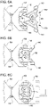
- Each inner link 108, 110 can have a two-piece construction as depicted at FIGS. 6A through 6C , which also depict a technique for assembling the inner links to the outer links.
- first link portion 108a and second link portion 108b of the proximal inner link 108 are positioned to place protruding journals 140 into journal bearings 142 of the middle outer link 102.
- the first link portion 108a and second link portion 108b are inserted at angles such that gear teeth 148 of each portion intermesh to cause alignment of the portions into the formation shown at FIG. 6B .
- the gear teeth 148 are an assembly aid that eliminates the need for pins or other fasteners, and are not used for movement beyond assembly.
- proximal outer link 100 is assembled onto the remaining exposed protruding journals 140 into the formation shown at FIG. 6C .
- proximal outer link 100 is also of two-piece construction.
Abstract
Description
- The present application claims the benefit of
U.S. Provisional Appln. No. 62/385,621 filed September 9, 2016 - Minimally invasive surgical techniques are aimed at reducing the amount of extraneous tissue that is damaged during diagnostic or surgical procedures, thereby reducing patient recovery time, discomfort, and deleterious side effects. As a consequence, the average length of a hospital stay for standard surgery may be shortened significantly using minimally invasive surgical techniques. Also, patient recovery times, patient discomfort, surgical side effects, and time away from work may also be reduced with minimally invasive surgery.
- A common form of minimally invasive surgery is endoscopy, and a common form of endoscopy is laparoscopy, which is minimally invasive inspection and/or surgery inside the abdominal cavity. Reloadable stapling devices can be used in conjunction with these surgeries. Telesurgically controlled stapling devices can include servo controlled wrist joints that yaw and pitch at relatively extreme angles (e.g., up to and over 90 degrees). Such joints can place a large amount of strain on actuation components that must translate through the wrist at such angles. Accordingly, current actuation devices are often limited by the ability of actuation components to function under extreme angles.
- Embodiments disclosed herein relate to surgical devices having wrists that can yaw and pitch at relatively large angles. Such wrists can have a yaw axis spatially separated from a pitch axis, with both such axes being perpendicular to one another as well as a longitudinal axis that defines the extension of an arm or shaft of a telesurgically controlled device. In some cases, the yaw and pitch angles can be up to 45, 60, or 90 degrees.
- Such pitch and yaw angles require an extremely flexible actuation mechanism for opening and closing jaws of the surgical device and optionally actuating other implements such as cutting and/or stapling devices. In some embodiments, an actuation mechanism can include a pushing component. The pushing component can be adapted to be highly compressible under extreme angles, while being extremely flexible. The pushing component may not however, be well suited to tensile forces. Accordingly a separate pulling component can be used to apply tensile force for proximal movement and actuation of the surgical device. In a similar manner, the pulling component may not be well suited for compressive forces. However, the combination of the pushing and pulling component into one integrated device can be effectively used for both compressive and tensile force application (i.e., pushing and pulling) to actuate components of an end effector of a surgical device.
- The pushing component and the pulling component can be integrated along a shared axis with the pushing component being concentrically arranged about the pulling component. In some embodiments, the pushing component includes a coiled spring and the pulling component includes a braided cable. Alternatively the pulling component can be concentrically arranged about the pushing component.
- To enable a high degree of wrist flexibility, the wrist assembly can be constructed from outer links that define yaw and pitch geometry for the wrist assembly. The outer links can house a flexible portion of the actuation mechanism. However, compression of the actuation mechanism within a wrist can cause buckling and decrease efficiency of force transmission. To help mitigate such issues, inner links can be provided that connect the outer links to one another. The inner links can define a passage that constrains and limits lateral movement of the actuation mechanism, and thus mitigate buckling.
- Thus, in one aspect, an apparatus includes an elongated shaft, an end effector, and a wrist assembly. The elongated shaft extends along a first axis. The end effector includes an upper jaw and a lower jaw. The wrist assembly moveably connects the end effector to the elongated shaft. The wrist assembly includes a first outer link, a first inner link, and a second outer link. The first outer link is connected to the elongated shaft and movably coupled to the second outer link by the first inner link. The first outer link, the first inner link, and the second outer link define a proximal joint. A medial surface of the first outer link and a medial surface of the second outer link define a lumen in which the first inner link is disposed. The medial surface of the first outer link defines at least a first recess and the medial surface of the second outer link defines at least a second recess. A radial surface of the first inner link includes at least a first protrusion and a second protrusion. The first protrusion of the first inner link engages the first recess. The second protrusion of the inner link engages the second recess.
- In some embodiments of the apparatus, the wrist assembly is operable to reorient to the end effector relative to the elongated shaft about an axis that is perpendicular to the first axis. For example, in some embodiments of the apparatus, the proximal joint extends along a second axis that is perpendicular to the first axis.
- In some embodiments of the apparatus, the wrist assembly is operable to reorient to the end effector relative to the elongated shaft about each of two axes that are perpendicular to the first axis. For example, the wrist assembly can further include a second inner link and a third outer link. The third outer link is connected to the end effector and moveably coupled to the second outer link by the second inner link. The third outer link, the second inner link, and the second outer link define a distal joint. The wrist assembly can be configured to yaw and pitch at the proximal and distal joints, respectively. In some embodiments of the apparatus, each of the first inner link and the second inner link includes first and second clevis protruding journals.
- In some embodiments of the apparatus, the wrist assembly has an interior passage through which an actuation component extends. For example, some embodiments of the apparatus include an elongated drive member drivingly coupled with the end effector and extending through an interior passage defined by the first inner link. In some embodiments of the apparatus, the elongated drive member is operable to apply a distally directed force to the end effector. In some embodiments, the interior passage is closely formed about the elongated drive member to prevent the elongated drive member from buckling while applying the distally directed force to the end effector. In some embodiments, the wrist assembly includes an inner sheath within the interior passage through which the elongated drive member extends.
- In some embodiments of the apparatus, the first outer link and the second outer link interface so as to control relative orientation between the first outer link, the first inner link, and the second outer link during articulation of the wrist assembly. For example, in some embodiments, the first outer link and the second outer link include intermeshing gear teeth that control relative orientation between the first outer link, the first inner link, and the second outer link through a range of orientations between the second outer link and the first outer link. In some embodiments, the first inner link is passively constrained by the first outer link and the second outer link.
- In another aspect, an apparatus includes an elongated arm, and end effector, an elongated drive member, and a wrist assembly. The elongated arm extends along a first axis. The end effector includes an upper jaw and a lower jaw. The elongated drive member extends from the elongated arm and is drivingly coupled with the end effector for actuation of the end effector. The wrist assembly moveably connects the elongated arm to the end effector. The wrist assembly includes a plurality of outer links and a plurality of inner links. The wrist assembly is operable to yaw and pitch the end effector relative to the elongated arm. The inner links define an inner passage between the elongated arm and the end effector through which the elongated drive member extends.
- In some embodiments of the apparatus, the wrist assembly is operable to reorient to the end effector relative to the elongated shaft about an axis that is perpendicular to the first axis. For example, in some embodiments of the apparatus, the wrist assembly includes a proximal joint that extends along a second axis perpendicular to the first axis.
- In some embodiments of the apparatus, the wrist assembly is operable to reorient to the end effector relative to the elongated shaft about each of two axes that are perpendicular to the first axis. For example, the wrist assembly can further include a distal joint that extends along a third axis perpendicular to the first axis and the second axis. In some embodiments, the wrist assembly is configured to yaw at the proximal joint and pitch at the distal joint. In some embodiments, each of the inner links comprises first and second protruding j oumals.
- In some embodiments of the apparatus, the wrist assembly has an interior passage through which an actuation component extends. For example, some embodiments of the apparatus, the interior passage is closely formed about the elongated drive member to prevent the elongated drive member from buckling under compression. In some embodiments, the wrist assembly includes an inner sheath within the interior passage and through which the elongated drive member extends.
- In some embodiments of the apparatus, the outer links interface so as to control relative orientation between the outer links and the inner links. For example, in some embodiments, the outer links include intermeshing gear teeth that control relative orientation between the outer links and the inner links through a range of orientations between the outer links. In some embodiments, the inner links are passively constrained by the outer links.
- In some embodiments, the wrist assembly is actuated via tension members. For example, in some embodiments, the apparatus includes cable portions that extend through portions of the outer links and are articulated to articulate the wrist assembly.
- In another aspect, a surgical device includes an elongated shaft, an end effector, and a wrist assembly. The elongated shaft extends along a first axis. The end effector includes an upper jaw and a lower jaw. The wrist assembly moveably connects the end effector to the elongated shaft. The wrist assembly includes a first outer link, a first inner link, and a second outer link. The first outer link is connected to the elongated shaft and includes first gear teeth. The first inner link is pivotally coupled with the first outer link to rotate relative to the first outer link around a second axis oriented perpendicular to the first axis. The second outer link is pivotally coupled with the first inner link to rotate relative to the first inner link around a third axis parallel to the second axis and offset from the second axis. The second outer link includes second gear teeth that interface with the first gear teeth and control orientation of the first inner link relative to the first outer link and the first outer link throughout a range of orientations of the second outer link relative to the first outer link.
- The first inner link can be pivotally coupled with the first outer link and the second outer link using any suitable pivot connection. For example, in some embodiments of the surgical device: the first inner link includes a first pair of protruding journals aligned with the second axis and a second pair of protruding journals aligned with the third axis, the first outer link comprises a pair of first outer link journal bearings interfacing with the first pair of protruding journals, and the second outer link comprises a pair of second outer link journal bearings interfacing with the second pair of protruding journals.
- The first inner link, the first outer link, or the second outer link can have a multiple-piece construction to facilitate assembly of the wrist assembly. For example, in some embodiments of the surgical device, the first inner link has a multiple-piece construction comprising a first inner link first portion and a first inner link second portion. In some embodiments of the surgical device, the first inner link first portion and the first inner link second portion are configured to be interfaced with one of the first outer link and the second outer link via rotation of each of the first inner link first portion and the first inner link second portion relative to the one of the first outer link and the second outer link. In some embodiments of the surgical device, the other of the one of the first outer link and the second outer link has a multiple-piece construction adapted to accommodate assembly to the first inner link after the first inner link is assembled with the one of the first outer link and the second outer link.
- In some embodiments of the surgical device, the wrist assembly forms an aperture through which an actuation assembly extends. For example, in some embodiments, the first inner link forms the aperture and the surgical device includes an elongated drive member that extends through the aperture and is drivingly coupled with the end effector to actuate a mechanism of the end effector.
- In some embodiments of the surgical device, the wrist assembly is cable driven and configured to react both proximally-directed loads and distally-directed loads applied to the end effector without relying on cable tension to react the distally-directed loads to keep the wrist assembly components from separating. For example, in some embodiments, the surgical device includes cable portions drivingly coupled with the wrist assembly and articulated to articulate the wrist assembly and the first inner link is configured to react both tension and compression loads applied to the end effector by the drive member back to the first outer link so as to keep the second outer link interfaced with the first outer link even in the absence of any of the cable portions being under tension.
- In some embodiments of the surgical device, the wrist assembly is operable to reorient to the end effector relative to the elongated shaft about each of two axes that are perpendicular to the first axis. For example, the wrist assembly can further include a second inner link and a third outer link. The second inner link can be pivotally coupled with the second outer link to rotate relative to the second outer link around a fourth axis oriented perpendicular to the first axis and to the third axis. The third outer link can be pivotally coupled with the second inner link to rotate relative to the second inner link around a fifth axis parallel to the fourth axis and offset from the fourth axis. The third outer link can include gear teeth that interface with gear teeth of the second outer link and control orientation of the second inner link relative to the third outer link and the second outer link throughout a range of orientations of the third outer link relative to the second outer link.
- The second inner link can be pivotally coupled with the second outer link and the third outer link using any suitable pivot connection. For example, in some embodiments of the surgical device: the second inner link includes a first pair of protruding journals aligned with the fourth axis and a second pair of protruding journals aligned with the fifth axis, the second outer link includes a pair of second outer link journal bearings interfacing with the first pair of protruding journals of the second inner link; and the third outer link includes a pair of third outer link journal bearings interfacing with the second pair of protruding journals of the second inner link.
- The second inner link, the second outer link, or the third outer link can have a multiple-piece construction to facilitate assembly of the wrist assembly. For example, in some embodiments of the surgical device, the second inner link has a multiple-piece construction comprising a second inner link first portion and a second inner link second portion. In some embodiments, the second inner link first portion and the second inner link second portion are configured to be interfaced with one of the second outer link and the third outer link via rotation of each of the second inner link first portion and the second inner link second portion relative to the one of the second outer link and the third outer link. In some embodiments, the other of the one of the second outer link and the third outer link has a multiple-piece construction adapted to accommodate assembly to the second inner link after the second inner link is assembled with the one of the second outer link and the third outer link.
- In some embodiments of the surgical device, the wrist assembly forms an aperture through which an actuation assembly extends. For example, in some embodiments, the second inner link forms a second inner link aperture. The surgical device can include an elongated drive member that extends through the second inner link aperture and is drivingly coupled with the end effector to actuate a mechanism of the end effector.
- In some embodiments of the surgical device, the wrist assembly is cable driven and configured to react both proximally-directed loads and distally-directed loads applied to the end effector without relying on cable tension to react the distally-directed loads to keep the wrist assembly components from separating. For example, the surgical device can include cable portions drivingly coupled with the wrist assembly and articulated to articulate the wrist assembly. The first inner link and the second inner link can be configured to react both tension and compression loads applied to the end effector by the drive member back to the first outer link so as to keep the third outer link interfaced with the second outer link and the second outer link interfaced with the first outer link even in the absence of any of the cable portions being under tension.
-
-
FIGS. 1A-1C show views of a surgical tool, according to many embodiments. -
FIGS. 2A, 2B , and 3C shows a perspective, side, and bottom views of a surgical tool, according to many embodiments. -
FIGS. 3A and 3B show cross-sectional views of a surgical tool, according to many embodiments. -
FIG. 4A shows a perspective view of an actuation mechanism, according to many embodiments. -
FIG. 4B shows a cross-sectional view of an actuation mechanism, according to many embodiments. -
FIGS. 4C and 4D show perspective views of pushing members, according to many embodiments. -
FIG. 4E shows a cross-sectional view of an actuation mechanism, according to many embodiments. -
FIG. 5A shows a perspective view of a wrist assembly, according to many embodiments. -
FIG. 5B shows a cross-sectional view of a wrist assembly, according to many embodiments. -
FIG. 5C shows a perspective view of an outer link assembly, according to many embodiments. -
FIGS. 6A-6C show a method of assembling a wrist assembly, according to many embodiments. -
FIGS. 1A-1C show asurgical tool 10 that includes aproximal chassis 12, aninstrument shaft 14, and adistal end effector 16 having anupper jaw 18 that can be articulated to grip a patient tissue. Theproximal chassis 12 includesinput couplers 22 that may interface with and be driven by corresponding output couplers of a telesurgical surgery system, such as the system disclosed within Pub. No.US 2014/0183244 A1 , which is incorporated by reference herein. The input couplers 22 are drivingly coupled with one or more input members that are disposed within theinstrument shaft 14. The input members are drivingly coupled with theend effector 16. As shown atFIGS. 1B and 1C ,input couplers 22 of theproximal chassis 12 can be adapted to mate with various types of motor packs 13, such as stapler specific motor packs disclosed atU.S. Pat. No. 8,912,746 , or the universal motor packs disclosed atU.S. Pat. No. 8,529,582 , which are incorporated by reference herein. -
FIGS. 2A-2C show perspective, side, and top views of a distal end of thesurgical tool 10 including theend effector 16.End effector 16 is moveably connected to theinstrument shaft 14 by awrist assembly 24. Thewrist assembly 24 has at least two degree of freedom and provides for attachment of theend effector 16 to theelongated instrument shaft 14 for articulation of theend effector 16 about two orthogonal axes relative to theinstrument shaft 14. Thewrist assembly 24 is configured to yaw about axis 2-2, which is perpendicular toaxis 1 that theinstrument shaft 14 extends along. Thewrist assembly 24 is also configured to pitch about axis 3, which is perpendicular toaxis 1 andaxis 2. As shown, theyaw axis 2 is proximal (farther from the end effector 16) to the pitch axis 3, however this is not a requirement and in some embodiments theyaw axis 2 is distal to the pitch axis 3. -
FIGS. 3A and 3B are a cross-sectional views showing details ofend effector 16 that include theupper jaw 18 and alower jaw 26. Thelower jaw 26 can be configured to accommodate and support a removable or non-removable stapling cartridge. Theupper jaw 18 is pivotally coupled with thelower jaw 26 to articulate relative to thelower jaw 26 to clamp tissue. Abeam member 28 is driven from a proximal state shown atFIG. 3A to a distal state shown atFIG. 3B to actuate theupper jaw 18. Movement of thebeam member 28 can serve to forcibly secure theupper jaw 18 over tissue with respect to thelower jaw 16. Optionally, thebeam member 28 can also allow for cutting tissue and deploying staples from the cartridge into the cut tissue. - The
beam member 28 includes anupper beam portion 30 that is configured to slide within arail feature 32 of theupper jaw 18. Therail feature 32 includes aramp 34 for theupper beam portion 30 to engage from a proximalmost garage area 36. The open position shown atFIG. 3A can be maintained by a resilient device, such as a spring, or opened and closed by a secondary mechanism (not shown). Partial closure of theupper jaw 18 can be affected by distal movement of theupper beam portion 30 onto theramp 34. Complete closure of theupper jaw 18 is achieved when theupper beam portion 30 is moved distally past theramp 34 and onto therail feature 32. Proximal movement of theupper beam portion 30 off of theramp 34 removes the closure force applied by the beam member. A resilient device or secondary mechanism can then cause a closed or partially closedupper jaw 18 to open. Thus, back and forth movement of theupper beam portion 30 along theramp 34 can toggle theend effector 16 open and closed. - The
beam member 28 also includes alower beam portion 38 that configured to slide within arail feature 32 of thelower jaw 18. Thelower beam portion 38 can actuate a sled (such as disclosed in Pub. No.US 2014/0183244 A1 ) configured for ejecting staples out thelower jaw 26 during distal movement of thebeam member 28. Alternatively, thelower beam portion 30 can be integrated with such a sled. -
FIG. 4A shows a perspective view of thebeam member 28. Here, theupper beam portion 30 includes an integrated cuttingmember 40 that is configured to cut tissue. However, in other embodiments a tissue cutting device can be separate from thebeam member 28 or implemented into thebeam member 28 in a different manner. Theupper beam portion 30 includes anupper flange 42, which transversely extends from the integrated cuttingmember 40. The glidingportion 42 is configured to directly interface with therail feature 32 andramp 34. In a similar manner alower flange 44 is provided to slide with a rail feature of thelower jaw 26. Anelongated drive member 46 is attached to thebeam member 28 for providing distal and proximal movement to thedrive member 46. -
FIG. 4B shows a cross-sectional view of thebeam member 28 and drivemember 46. Thedrive member 46 includes a pushingmember 48 and a pullingmember 50. The pushingmember 48 is configured as a close-coiled spring and is adapted for translating axial force applied by adrive rod 52. The pushingmember 48 can be externally constrained by asheath 54, which can be constructed from a lubricous polymer material such as PTFE. The coiled design of the pushingmember 48 allows compressive force to be translated effectively to thebeam member 28 to push thebeam member 28 in the distal direction. The pushingmember 48 can be constructed from a coiled wire in the conventional manner or be spirally cut from a tube. In some cases, the compressive elements (e.g., coils) of the pushing member will separate under tension, and thus in such cases the pushing member can only be effective for transfer of compressive forces. - The pulling
member 50 can be constructed from a braided cable or other flexible rod and retained within thebeam member 28 bycrimp portion 56. In some cases, the pulling member may be relatively ineffective for transfer of pushing forces as it can have the tendency to collapse or buckle on itself, , and thus in such cases the pulling member can only be effective for transfer of tensile forces. The pullingmember 50 is also adapted for translating axial force applied by adrive rod 52. Thedrive rod 52 is located within theinstrument shaft 14 and is drivingly coupled to one or more of theinput couplers 22 shown atFIG. 1 . The pullingmember 50 allows tensile force to be translated effectively from thedrive rod 52 to thebeam member 28, to pull thebeam member 28 in the proximal direction. The pushingmember 48 and pullingmember 50 operate in a complementary manner to provide distal and proximal motion to thebeam member 28 by segregating tensile forces to the pullingmember 50 and the compressive forces to the pushingmember 48. This enables a very flexible and compact design for thedrive member 46, characteristics that enable thedrive member 46 to translate within thewrist 24, which can be disposed at torturous yaw and pitch angles during operation. - The pushing member is not limited to a close-coiled spring design as depicted at
FIG. 4B . For example, a flexible pushingmember 58 as shown atFIG. 4C can be formed from a solid tube by cutting a pattern into the solid tube to increase bending flexibility at the wrist without materially decreasing compressive stiffness. Here, the pushingmember 58 is formed by laser cutting a pattern into a metal tube. The pattern here allows for flexibility where gaps are formed in the tube and axial stiffness where material is left in place. Another example of a flexible pushing member is depicted atFIG. 4D , which shows a pushingmember 60 having a plurality of circumferential slits arranged in a spiraling pattern. -
FIG. 4E shows an alternative configuration of adrive member 60. The configuration here is the opposite as what is depicted atFIG. 4B in which the pushingmember 48 is concentrically surrounds the pullingmember 50. Here, thedrive member 60 includes a pullingmember 62 configured as an braided sheath that encapsulates a pushingmember 64. The pushingmember 64 is configured as a plurality of spherical members (e.g., ball bearings) joined by aflexible rod 66. Both the pushingmember 64 and pullingmember 62 are actuated by thedrive rod 52, which is drivingly coupled to one or more of theinput couplers 22 shown atFIG. 1 . -
FIG. 5A and5B show perspective and cross-sectional views of thewrist assembly 24. Thewrist assembly 24 includes a proximalouter link 100, a middleouter link 102, and a distalouter link 104. These three links determine the kinematic pitch and yaw motion of thewrist assembly 24. As shown, the interface between the proximalouter link 100 and the middleouter link 102 determine yaw movement of thewrist assembly 24. The interface between the outerdistal link 104 and the middleouter link 102 determine pitch movement of thewrist assembly 24. However, in an alternative wrist configuration, this relationship can be reversed such that thewrist assembly 24 pitches between the proximalouter link 100 and the middleouter link 102 and yaws between the distalouter link 100 and the middle outer link 102 (e.g., by rotating theend effector 16 relative towrist assembly 24 by 90 degrees). -
Cable portions 106 are drivingly coupled with thewrist assembly 24 and actuated to impart motion to thewrist assembly 24. In some embodiments,cable portions 106 can be individually secured to a portion of the distalouter link 104. In an functionally equivalent alternate embodiment, as shown atFIG. 5A ,cable portions 106 are looped about a portion of the distalouter link 104 as shown. Loopingcable portions 106 to the distalouter link 104 can be used to secure thecable portions 106 to the distalouter link 104. Thecable portions 106 can be articulated to articulate thewrist assembly 24. Differential movement of thecable portions 106 can be used to actuate thewrist assembly 24 to pitch and yaw at various angles. Thecable portions 106 can be drivingly coupled to one or more of theinput couplers 22 shown atFIG. 1 . The wrist assembly also includes proximalinner link 108 and distalinner link 110, which are discussed in detail below. - With attention to
FIG. 5C , an exemplary embodiment of a joint 112 is shown that is representative of the interfaces between the outer links shown atFIGS. 5A and5B . The joint 112 includes afirst link 114 and asecond link 116. First link 114 may includegear teeth bearing projection 122. Thesecond link 116 includesgear teeth bearing projection 130. According to an exemplary embodiment,projections second links cable portions 106 to pass through. Because bearingprojections central apertures cable portions 106 extending through passages adjacent to bearingprojections central apertures links gear teeth projections gear teeth - Due to the enhanced range of motion provided by joint 112, a wrist including joint 112 may provide a desired amount of motion, such as +/- 90 degrees in a pitch or yaw direction, in a more efficient manner with fewer parts. In previous wrist structures in which each joint is limited to a maximum roll angle of about 45 degrees, several such joints in series are needed to achieve relatively large roll angle for the entire wrist mechanism. In the illustrated embodiment, a single joint 112 can provide up to a 90 degree angular deflection. As a result, manufacturing cost and complexity for a wrist that includes one or
more joints 112 may be reduced while still achieving desired angular deflection. In addition, thegear teeth links links links links links joints 112 to achieve higher ranges of motion (up to roll limit angles), such as, for example, wrists having a range of motion of up to +/- 180 degrees in a pitch or yaw direction. Additional details of joint 112, and other joints usable with the embodiments disclosed herein, are disclosed in Int'l. Pub. No.WO 2015/127250 , which is incorporated by reference herein. - As shown at
FIG. 5B , the proximal and distalinner links axis 1 and offset 90 degrees from one another. Hence, the proximalinternal link 108 is only partially shown. Radial surfaces of the proximal and distalinner links journals 140 and thejournal bearings 142 set the distances between the outer links, but otherwise are passive and do not alter joint kinematics of the outer links which is determined by the geometry of thegear teeth inner links journals 120 that interface with thejournals bearings 142 for a total of four protrudingjournals 140 perinner link journals 140 is separated to provide aninternal passage 144 for thedrive member 46. - An additional
internal sheath 146 can be used to further support thedrive member 46. Thedrive member 46 slides axially within theinternal sheath 146. Theinternal sheath 146 is fixed to a distal end portion of thewrist assembly 24 and is flexible to bend with movement of thewrist assembly 24 but does not move axially. Theinternal sheath 146 andinternal passage 144 provided by theinner links drive member 46 during axial movement.Internal sheath 146 andinner passage 144 prevent the drive member from buckling under compressive loading (i.e. distal movement while cutting and stapling). Prior wrist designs, such as disclosed in the aforementioned Int'l. Pub. No.WO 2015/127250 , rely on tensioned cables to maintain the outer links in position. Here, when thedrive member 46 moves in a distal direction the resulting compressive force can be reacted by via theinner links cables 106. The protrudingjournals 140 of theinner links drive member 46 moves in a distal direction, therefore maintaining the structure of thewrist assembly 24. - Each
inner link FIGS. 6A through 6C , which also depict a technique for assembling the inner links to the outer links. AtFIG. 6A first link portion 108a andsecond link portion 108b of the proximalinner link 108 are positioned to place protrudingjournals 140 intojournal bearings 142 of the middleouter link 102. Thefirst link portion 108a andsecond link portion 108b are inserted at angles such that gear teeth 148 of each portion intermesh to cause alignment of the portions into the formation shown atFIG. 6B . The gear teeth 148 are an assembly aid that eliminates the need for pins or other fasteners, and are not used for movement beyond assembly. However, in some embodiments, fasteners can be used in lieu of the gear teeth. After thelink portions proximal link 108, the proximalouter link 100 is assembled onto the remaining exposed protrudingjournals 140 into the formation shown atFIG. 6C . In one embodiment, as shown atFIG. 6C , proximalouter link 100 is also of two-piece construction. - Other variations are within the spirit of the present invention. The various aspects, embodiments, implementations or features of the described embodiments can be used separately or in any combination. Various aspects of the described embodiments associated with operation of telesurgical tools can be implemented by software, hardware or a combination of hardware and software. Thus, while the invention is susceptible to various modifications and alternative constructions, certain illustrated embodiments thereof are shown in the drawings and have been described above in detail. It should be understood, however, that there is no intention to limit the invention to the specific form or forms disclosed, but on the contrary, the intention is to cover all modifications, alternative constructions, and equivalents falling within the spirit and scope of the invention, as defined in the appended claims.
- The use of the terms "a" and "an" and "the" and similar referents in the context of describing the invention (especially in the context of the following claims) are to be construed to cover both the singular and the plural, unless otherwise indicated herein or clearly contradicted by context. The terms "comprising," "having," "including," and "containing" are to be construed as open-ended terms (i.e., meaning "including, but not limited to,") unless otherwise noted. The term "connected" is to be construed as partly or wholly contained within, attached to, or joined together, even if there is something intervening. Recitation of ranges of values herein are merely intended to serve as a shorthand method of referring individually to each separate value falling within the range, unless otherwise indicated herein, and each separate value is incorporated into the specification as if it were individually recited herein. All methods described herein can be performed in any suitable order unless otherwise indicated herein or otherwise clearly contradicted by context. The use of any and all examples, or exemplary language (e.g., "such as") provided herein, is intended merely to better illuminate embodiments of the invention and does not pose a limitation on the scope of the invention unless otherwise claimed. No language in the specification should be construed as indicating any non-claimed element as essential to the practice of the invention.
- Preferred embodiments of this invention are described herein, including the best mode known to the inventors for carrying out the invention. Variations of those preferred embodiments may become apparent to those of ordinary skill in the art upon reading the foregoing description. The inventors expect skilled artisans to employ such variations as appropriate, and the inventors intend for the invention to be practiced otherwise than as specifically described herein. Accordingly, this invention includes all modifications and equivalents of the subject matter recited in the claims appended hereto as permitted by applicable law. Moreover, any combination of the above-described elements in all possible variations thereof is encompassed by the invention unless otherwise indicated herein or otherwise clearly contradicted by context.
- The present application also includes the following numbered clauses:
- 1. An apparatus comprising:
- an elongated shaft extending along a first axis;
- an end effector comprising an upper jaw and a lower jaw;
- a wrist assembly moveably connecting the end effector to the elongated shaft, the wrist assembly comprising:
- a first outer link, a first inner link, and a second outer link; the first outer link being connected to the elongated shaft and movably coupled to the second outer link by the first inner link; the first outer link, the first inner link, and the second outer link defining a proximal joint;
- wherein a medial surface of the first outer link and a medial surface of the second outer link define a lumen in which the first inner link is disposed;
- wherein the medial surface of the first outer link defines at least a first recess and the medial surface of the second outer link defines at least a second recess;
- wherein a radial surface of the first inner link includes at least a first protrusion and a second protrusion;
- wherein the first protrusion of the first inner link engages the first recess, and the second protrusion of the inner link engages the second recess.
- 2. The apparatus of
clause 1, wherein the proximal joint extends along a second axis that is perpendicular to the first axis. - 3. The apparatus of
clause 1, wherein the wrist assembly further comprises a second inner link and a third outer link, the third outer link being connected to the end effector and moveably coupled to the second outer link by the second inner link; the third outer link, the second inner link, and the second outer link defining a distal joint. - 4. The apparatus of clause 3, wherein the wrist assembly is configured to yaw and pitch at the proximal and distal joints, respectively.
- 5. The apparatus of clause 3, each of the first inner link and the second inner link comprises first and second clevis protruding journals.
- 5. The apparatus of
clause 1, further comprising an elongated drive member drivingly coupled with the end effector, the elongated drive member extending through an interior passage defined by the first inner link. - 7. The apparatus of clause 6, wherein the elongated drive member is operable to apply a distally directed force to the end effector.
- 8. The apparatus of
clause 7, wherein the interior passage is closely formed about the elongated drive member to prevent the elongated drive member from buckling while applying the distally directed force to the end effector. - 9. The apparatus of
clause 1, wherein the first outer link and the second outer link comprise intermeshing gear teeth that control relative orientation between the first outer link, the first inner link, and the second outer link through a range of orientations between the second outer link and the first outer link. - 10. The apparatus of
clause 1, wherein the first inner link is passively constrained by the first outer link and the second outer link. - 11. The apparatus of
clause 1, wherein the wrist assembly comprises an inner sheath within the interior passage through which the elongated drive member extends. - 12. An apparatus comprising:
- an elongated arm extending along a first axis;
- an end effector comprising an upper jaw and a lower jaw;
- an elongated drive member extending from the elongated arm and drivingly coupled with the end effector for actuation of the end effector; and
- a wrist assembly moveably connecting the elongated arm to the end effector, the wrist assembly comprising a plurality of outer links and a plurality of inner links, the wrist assembly being operable to yaw and pitch the end effector relative to the elongated arm, the inner links defining an inner passage between the elongated arm and the end effector through which the elongated drive member extends.
- 13. The apparatus of
clause 12, wherein the wrist assembly comprises a proximal joint that extends along a second axis perpendicular to the first axis. - 14. The apparatus of
clause 13, wherein the wrist assembly comprise a distal joint that extends along a third axis perpendicular to the first axis and the second axis. - 15. The apparatus of
clause 14, wherein the wrist assembly is configured to yaw at the proximal joint and pitch at the distal joint. - 16. The apparatus of clause 15, each of the inner links comprises first and second protruding journals.
- 17. The apparatus of
clause 12, wherein the interior passage is closely formed about the elongated drive member to prevent the elongated drive member from buckling under compression. - 18. The apparatus of
clause 12, wherein the outer links comprise intermeshing gear teeth that control relative orientation between the outer links and the inner links through a range of orientations between the outer links. - 19. The apparatus of
clause 18, wherein the inner links are passively constrained by the outer links. - 20. The apparatus of
clause 12, wherein the wrist assembly comprises an inner sheath within the interior passage and through which the elongated drive member extends. - 21. The apparatus of
clause 12, further comprising cable portions that extend through portions of the outer links and are articulated to articulate the wrist assembly. - 22. A surgical device comprising:
- an elongated shaft extending along a first axis;
- an end effector comprising an upper jaw and a lower jaw;
- a wrist assembly moveably connecting the end effector to the elongated shaft, the wrist assembly comprising:
- a first outer link connected to the elongated shaft and comprising first gear teeth;
- a first inner link pivotally coupled with the first outer link to rotate relative to the first outer link around a second axis oriented perpendicular to the first axis;
- a second outer link pivotally coupled with the first inner link to rotate relative to the first inner link around a third axis parallel to the second axis and offset from the second axis, the second outer link comprising second gear teeth that interface with the first gear teeth and control orientation of the first inner link relative to the first outer link and the first outer link throughout a range of orientations of the second outer link relative to the first outer link.
- 23. The surgical device of
clause 22, wherein:- the first inner link comprises a first pair of protruding journals aligned with the second axis and a second pair of protruding journals aligned with the third axis;
- the first outer link comprises a pair of first outer link journal bearings interfacing with the first pair of protruding journals; and
- the second outer link comprises a pair of second outer link journal bearings interfacing with the second pair of protruding journals.
- 24. The surgical device of any one of
clause 22 and clause 23, wherein the first inner link has a multiple-piece construction comprising a first inner link first portion and a first inner link second portion. - 25. The surgical device of
clause 24, wherein the first inner link first portion and the first inner link second portion are configured to be interfaced with one of the first outer link and the second outer link via rotation of each of the first inner link first portion and the first inner link second portion relative to the one of the first outer link and the second outer link. - 26. The surgical device of clause 25, wherein the other of the one of the first outer link and the second outer link has a multiple-piece construction adapted to accommodate assembly to the first inner link after the first inner link is assembled with the one of the first outer link and the second outer link.
- 27. The surgical device of
clause 22, wherein the first inner link forms an aperture, the surgical device further comprising an elongated drive member that extends through the aperture and is drivingly coupled with the end effector to actuate a mechanism of the end effector. - 28. The surgical device of clause 27, further comprising cable portions drivingly coupled with the wrist assembly and articulated to articulate the wrist assembly, and wherein the first inner link is configured to react both tension and compression loads applied to the end effector by the drive member back to the first outer link so as to keep the second outer link interfaced with the first outer link even in the absence of any of the cable portions being under tension.
- 29. The surgical device of
clause 22, wherein the wrist assembly further comprises:- a second inner link pivotally coupled with the second outer link to rotate relative to the second outer link around a fourth axis oriented perpendicular to the first axis and to the third axis;
- a third outer link pivotally coupled with the second inner link to rotate relative to the second inner link around a fifth axis parallel to the fourth axis and offset from the fourth axis, the third outer link comprising gear teeth that interface with gear teeth of the second outer link and control orientation of the second inner link relative to the third outer link and the second outer link throughout a range of orientations of the third outer link relative to the second outer link.
- 30. The surgical device of clause 29, wherein:
- the second inner link comprises a first pair of protruding journals aligned with the fourth axis and a second pair of protruding journals aligned with the fifth axis;
- the second outer link comprises a pair of second outer link journal bearings interfacing with the first pair of protruding journals of the second inner link; and
- the third outer link comprises a pair of third outer link journal bearings interfacing with the second pair of protruding journals of the second inner link.
- 31. The surgical device of any one of clause 29 and
clause 30, wherein the second inner link has a multiple-piece construction comprising a second inner link first portion and a second inner link second portion. - 32. The surgical device of clause 31, wherein the second inner link first portion and the second inner link second portion are configured to be interfaced with one of the second outer link and the third outer link via rotation of each of the second inner link first portion and the second inner link second portion relative to the one of the second outer link and the third outer link.
- 33. The surgical device of
clause 32, wherein the other of the one of the second outer link and the third outer link has a multiple-piece construction adapted to accommodate assembly to the second inner link after the second inner link is assembled with the one of the second outer link and the third outer link. - 34. The surgical device of clause 29, wherein the second inner link forms a second inner link aperture, the surgical device further comprising an elongated drive member that extends through the second inner link aperture and is drivingly coupled with the end effector to actuate a mechanism of the end effector.
- 35. The surgical device of
clause 34, further comprising cable portions drivingly coupled with the wrist assembly and articulated to articulate the wrist assembly, and wherein the first inner link and the second inner link are configured to react both tension and compression loads applied to the end effector by the drive member back to the first outer link so as to keep the third outer link interfaced with the second outer link and the second outer link interfaced with the first outer link even in the absence of any of the cable portions being under tension.
Claims (15)
- A surgical device comprising:a shaft extending along a longitudinal axis;an end effector; anda wrist assembly coupling the end effector to the shaft, the wrist assembly comprising:a first outer link connected to the shaft and comprising first gear teeth;an inner link pivotally coupled with the first outer link to rotate relative to the first outer link around a first axis oriented non-parallel to the longitudinal axis; anda second outer link pivotally coupled with the inner link to rotate relative to the inner link around a second axis parallel to and offset from the first axis, the second outer link comprising second gear teeth;wherein the first gear teeth and the second gear teeth are arranged to successively intermesh to control a relative orientation between the first outer link and the second outer link.
- The surgical device of claim 1, wherein:the inner link comprises a first pair of protruding journals aligned with the first axis and a second pair of protruding journals aligned with the second axis;the first outer link comprises a pair of first outer link journal bearings interfacing with the first pair of protruding journals; andthe second outer link comprises a pair of second outer link journal bearings interfacing with the second pair of protruding journals.
- The surgical device of claim 2, wherein the inner link has a multiple-piece construction comprising a first portion and a second portion coupled to one another.
- The surgical device of claim 3, wherein the first portion and the second portion couple to one another along an interface that extends generally along the longitudinal axis.
- The surgical device of any one of claims 2-4, wherein:the surgical device further comprises a drive member extending through the shaft and coupled with the end effector to transmit drive force to actuate the end effector; andthe inner link comprises an aperture through which the drive member extends.
- The surgical device of any one of claims 2-5, wherein:the first outer link is configured to rotate relative to the inner link about a first axis defined by the pair of first outer link journal bearings and the first pair of protruding journals; andthe second outer link is configured to rotate relative to the inner link about a second axis defined by the pair of second outer link journal bearings and the second pair of protruding journals, the second axis being parallel to and offset from the first axis.
- The surgical device of claim 6, wherein each of the first axis and the second axis are perpendicular to the longitudinal axis.
- The surgical device of claim 6, wherein the inner link is a first inner link and the wrist assembly further comprises a second inner link and a third outer link, the third outer link being coupled to the end effector and the second inner link disposed radially inward of the second outer link and the third outer link and moveably coupling the second and third outer links.
- The surgical device of claim 8, wherein the first outer link and second outer link are movably coupled by the first inner link to move the end effector in one of a pitch range of motion or a yaw range of motion relative to the shaft.
- The surgical device of claim 9, wherein the second outer link and third outer link are movably coupled by the second inner link to move the end effector in the other of the pitch range of motion or the yaw range of motion relative to the shaft.
- The surgical device of any one of claims 2-10, wherein:the first pair of protruding journals are radially opposite one another relative to the longitudinal axis; andthe pair of first outer link journal bearings are radially opposite one another relative to the longitudinal axis.
- The surgical device of any one of claims 2-10, wherein:the second pair of protruding journals are radially opposite one another relative to the longitudinal axis; andthe pair of second outer link journal bearings are radially opposite one another relative to the longitudinal axis.
- The surgical device of any one of claims 1-12, further comprising one or more cables extending through the first outer link and the second outer link.
- The surgical device of claim 13, wherein the first outer link and second outer link are rotatable relative to one another in response to force transmitted by the one or more cables.
- The surgical device of any one of claims 1-14, wherein:the first outer link comprises a first bearing surface;the second outer link comprises a second bearing surface;the first outer link and second outer link are articulatable relative to one another over a range of motion; andthe first bearing surface and the second bearing surface are configured to engage one another throughout the range of motion.
Applications Claiming Priority (3)
| Application Number | Priority Date | Filing Date | Title |
|---|---|---|---|
| US201662385621P | 2016-09-09 | 2016-09-09 | |
| PCT/US2017/050754 WO2018049211A1 (en) | 2016-09-09 | 2017-09-08 | Wrist architecture |
| EP17849645.1A EP3509511B1 (en) | 2016-09-09 | 2017-09-08 | Wrist architecture |
Related Parent Applications (2)
| Application Number | Title | Priority Date | Filing Date |
|---|---|---|---|
| EP17849645.1A Division EP3509511B1 (en) | 2016-09-09 | 2017-09-08 | Wrist architecture |
| EP17849645.1A Division-Into EP3509511B1 (en) | 2016-09-09 | 2017-09-08 | Wrist architecture |
Publications (1)
| Publication Number | Publication Date |
|---|---|
| EP4122408A1 true EP4122408A1 (en) | 2023-01-25 |
Family
ID=61562696
Family Applications (2)
| Application Number | Title | Priority Date | Filing Date |
|---|---|---|---|
| EP22190853.6A Pending EP4122408A1 (en) | 2016-09-09 | 2017-09-08 | Wrist architecture |
| EP17849645.1A Active EP3509511B1 (en) | 2016-09-09 | 2017-09-08 | Wrist architecture |
Family Applications After (1)
| Application Number | Title | Priority Date | Filing Date |
|---|---|---|---|
| EP17849645.1A Active EP3509511B1 (en) | 2016-09-09 | 2017-09-08 | Wrist architecture |
Country Status (6)
| Country | Link |
|---|---|
| US (3) | US11234700B2 (en) |
| EP (2) | EP4122408A1 (en) |
| JP (3) | JP6989594B2 (en) |
| KR (1) | KR102467745B1 (en) |
| CN (2) | CN115399819A (en) |
| WO (1) | WO2018049211A1 (en) |
Families Citing this family (251)
| Publication number | Priority date | Publication date | Assignee | Title |
|---|---|---|---|---|
| US9060770B2 (en) | 2003-05-20 | 2015-06-23 | Ethicon Endo-Surgery, Inc. | Robotically-driven surgical instrument with E-beam driver |
| US20070084897A1 (en) | 2003-05-20 | 2007-04-19 | Shelton Frederick E Iv | Articulating surgical stapling instrument incorporating a two-piece e-beam firing mechanism |
| US11896225B2 (en) | 2004-07-28 | 2024-02-13 | Cilag Gmbh International | Staple cartridge comprising a pan |
| US7669746B2 (en) | 2005-08-31 | 2010-03-02 | Ethicon Endo-Surgery, Inc. | Staple cartridges for forming staples having differing formed staple heights |
| US11246590B2 (en) | 2005-08-31 | 2022-02-15 | Cilag Gmbh International | Staple cartridge including staple drivers having different unfired heights |
| US11484312B2 (en) | 2005-08-31 | 2022-11-01 | Cilag Gmbh International | Staple cartridge comprising a staple driver arrangement |
| US7934630B2 (en) | 2005-08-31 | 2011-05-03 | Ethicon Endo-Surgery, Inc. | Staple cartridges for forming staples having differing formed staple heights |
| US10159482B2 (en) | 2005-08-31 | 2018-12-25 | Ethicon Llc | Fastener cartridge assembly comprising a fixed anvil and different staple heights |
| US20070106317A1 (en) | 2005-11-09 | 2007-05-10 | Shelton Frederick E Iv | Hydraulically and electrically actuated articulation joints for surgical instruments |
| US8820603B2 (en) | 2006-01-31 | 2014-09-02 | Ethicon Endo-Surgery, Inc. | Accessing data stored in a memory of a surgical instrument |
| US20120292367A1 (en) | 2006-01-31 | 2012-11-22 | Ethicon Endo-Surgery, Inc. | Robotically-controlled end effector |
| US11793518B2 (en) | 2006-01-31 | 2023-10-24 | Cilag Gmbh International | Powered surgical instruments with firing system lockout arrangements |
| US8708213B2 (en) | 2006-01-31 | 2014-04-29 | Ethicon Endo-Surgery, Inc. | Surgical instrument having a feedback system |
| US20110295295A1 (en) | 2006-01-31 | 2011-12-01 | Ethicon Endo-Surgery, Inc. | Robotically-controlled surgical instrument having recording capabilities |
| US7845537B2 (en) | 2006-01-31 | 2010-12-07 | Ethicon Endo-Surgery, Inc. | Surgical instrument having recording capabilities |
| US8186555B2 (en) | 2006-01-31 | 2012-05-29 | Ethicon Endo-Surgery, Inc. | Motor-driven surgical cutting and fastening instrument with mechanical closure system |
| US8992422B2 (en) | 2006-03-23 | 2015-03-31 | Ethicon Endo-Surgery, Inc. | Robotically-controlled endoscopic accessory channel |
| US10568652B2 (en) | 2006-09-29 | 2020-02-25 | Ethicon Llc | Surgical staples having attached drivers of different heights and stapling instruments for deploying the same |
| US8684253B2 (en) | 2007-01-10 | 2014-04-01 | Ethicon Endo-Surgery, Inc. | Surgical instrument with wireless communication between a control unit of a robotic system and remote sensor |
| US8701958B2 (en) | 2007-01-11 | 2014-04-22 | Ethicon Endo-Surgery, Inc. | Curved end effector for a surgical stapling device |
| US8931682B2 (en) | 2007-06-04 | 2015-01-13 | Ethicon Endo-Surgery, Inc. | Robotically-controlled shaft based rotary drive systems for surgical instruments |
| US11564682B2 (en) | 2007-06-04 | 2023-01-31 | Cilag Gmbh International | Surgical stapler device |
| US11849941B2 (en) | 2007-06-29 | 2023-12-26 | Cilag Gmbh International | Staple cartridge having staple cavities extending at a transverse angle relative to a longitudinal cartridge axis |
| US9179912B2 (en) | 2008-02-14 | 2015-11-10 | Ethicon Endo-Surgery, Inc. | Robotically-controlled motorized surgical cutting and fastening instrument |
| JP5410110B2 (en) | 2008-02-14 | 2014-02-05 | エシコン・エンド−サージェリィ・インコーポレイテッド | Surgical cutting / fixing instrument with RF electrode |
| US8636736B2 (en) | 2008-02-14 | 2014-01-28 | Ethicon Endo-Surgery, Inc. | Motorized surgical cutting and fastening instrument |
| US7866527B2 (en) | 2008-02-14 | 2011-01-11 | Ethicon Endo-Surgery, Inc. | Surgical stapling apparatus with interlockable firing system |
| US7819298B2 (en) | 2008-02-14 | 2010-10-26 | Ethicon Endo-Surgery, Inc. | Surgical stapling apparatus with control features operable with one hand |
| US9204923B2 (en) | 2008-07-16 | 2015-12-08 | Intuitive Surgical Operations, Inc. | Medical instrument electronically energized using drive cables |
| US8210411B2 (en) | 2008-09-23 | 2012-07-03 | Ethicon Endo-Surgery, Inc. | Motor-driven surgical cutting instrument |
| US11648005B2 (en) | 2008-09-23 | 2023-05-16 | Cilag Gmbh International | Robotically-controlled motorized surgical instrument with an end effector |
| US9005230B2 (en) | 2008-09-23 | 2015-04-14 | Ethicon Endo-Surgery, Inc. | Motorized surgical instrument |
| US9386983B2 (en) | 2008-09-23 | 2016-07-12 | Ethicon Endo-Surgery, Llc | Robotically-controlled motorized surgical instrument |
| US8608045B2 (en) | 2008-10-10 | 2013-12-17 | Ethicon Endo-Sugery, Inc. | Powered surgical cutting and stapling apparatus with manually retractable firing system |
| US9566061B2 (en) | 2010-09-30 | 2017-02-14 | Ethicon Endo-Surgery, Llc | Fastener cartridge comprising a releasably attached tissue thickness compensator |
| US10945731B2 (en) | 2010-09-30 | 2021-03-16 | Ethicon Llc | Tissue thickness compensator comprising controlled release and expansion |
| US9629814B2 (en) | 2010-09-30 | 2017-04-25 | Ethicon Endo-Surgery, Llc | Tissue thickness compensator configured to redistribute compressive forces |
| US11812965B2 (en) | 2010-09-30 | 2023-11-14 | Cilag Gmbh International | Layer of material for a surgical end effector |
| US9386988B2 (en) | 2010-09-30 | 2016-07-12 | Ethicon End-Surgery, LLC | Retainer assembly including a tissue thickness compensator |
| US8746535B2 (en) | 2010-09-30 | 2014-06-10 | Ethicon Endo-Surgery, Inc. | Tissue thickness compensator comprising detachable portions |
| US11849952B2 (en) | 2010-09-30 | 2023-12-26 | Cilag Gmbh International | Staple cartridge comprising staples positioned within a compressible portion thereof |
| US9839420B2 (en) | 2010-09-30 | 2017-12-12 | Ethicon Llc | Tissue thickness compensator comprising at least one medicament |
| US8695866B2 (en) | 2010-10-01 | 2014-04-15 | Ethicon Endo-Surgery, Inc. | Surgical instrument having a power control circuit |
| AU2012250197B2 (en) | 2011-04-29 | 2017-08-10 | Ethicon Endo-Surgery, Inc. | Staple cartridge comprising staples positioned within a compressible portion thereof |
| US9072535B2 (en) | 2011-05-27 | 2015-07-07 | Ethicon Endo-Surgery, Inc. | Surgical stapling instruments with rotatable staple deployment arrangements |
| RU2639857C2 (en) | 2012-03-28 | 2017-12-22 | Этикон Эндо-Серджери, Инк. | Tissue thickness compensator containing capsule for medium with low pressure |
| MX358135B (en) | 2012-03-28 | 2018-08-06 | Ethicon Endo Surgery Inc | Tissue thickness compensator comprising a plurality of layers. |
| US9101358B2 (en) | 2012-06-15 | 2015-08-11 | Ethicon Endo-Surgery, Inc. | Articulatable surgical instrument comprising a firing drive |
| US9649111B2 (en) | 2012-06-28 | 2017-05-16 | Ethicon Endo-Surgery, Llc | Replaceable clip cartridge for a clip applier |
| US9226751B2 (en) | 2012-06-28 | 2016-01-05 | Ethicon Endo-Surgery, Inc. | Surgical instrument system including replaceable end effectors |
| US20140001231A1 (en) | 2012-06-28 | 2014-01-02 | Ethicon Endo-Surgery, Inc. | Firing system lockout arrangements for surgical instruments |
| US9289256B2 (en) | 2012-06-28 | 2016-03-22 | Ethicon Endo-Surgery, Llc | Surgical end effectors having angled tissue-contacting surfaces |
| RU2672520C2 (en) | 2013-03-01 | 2018-11-15 | Этикон Эндо-Серджери, Инк. | Hingedly turnable surgical instruments with conducting ways for signal transfer |
| US9867612B2 (en) | 2013-04-16 | 2018-01-16 | Ethicon Llc | Powered surgical stapler |
| BR112015026109B1 (en) | 2013-04-16 | 2022-02-22 | Ethicon Endo-Surgery, Inc | surgical instrument |
| US9775609B2 (en) | 2013-08-23 | 2017-10-03 | Ethicon Llc | Tamper proof circuit for surgical instrument battery pack |
| CN105813582B (en) | 2013-12-11 | 2019-05-28 | 柯惠Lp公司 | Wrist units and clamp assemblies for robotic surgical system |
| US9826977B2 (en) | 2014-03-26 | 2017-11-28 | Ethicon Llc | Sterilization verification circuit |
| US20150297223A1 (en) | 2014-04-16 | 2015-10-22 | Ethicon Endo-Surgery, Inc. | Fastener cartridges including extensions having different configurations |
| JP6532889B2 (en) | 2014-04-16 | 2019-06-19 | エシコン エルエルシーEthicon LLC | Fastener cartridge assembly and staple holder cover arrangement |
| CN106456176B (en) | 2014-04-16 | 2019-06-28 | 伊西康内外科有限责任公司 | Fastener cartridge including the extension with various configuration |
| US20160066913A1 (en) | 2014-09-05 | 2016-03-10 | Ethicon Endo-Surgery, Inc. | Local display of tissue parameter stabilization |
| BR112017004361B1 (en) | 2014-09-05 | 2023-04-11 | Ethicon Llc | ELECTRONIC SYSTEM FOR A SURGICAL INSTRUMENT |
| US11523821B2 (en) | 2014-09-26 | 2022-12-13 | Cilag Gmbh International | Method for creating a flexible staple line |
| US9924944B2 (en) | 2014-10-16 | 2018-03-27 | Ethicon Llc | Staple cartridge comprising an adjunct material |
| US11141153B2 (en) | 2014-10-29 | 2021-10-12 | Cilag Gmbh International | Staple cartridges comprising driver arrangements |
| US10517594B2 (en) | 2014-10-29 | 2019-12-31 | Ethicon Llc | Cartridge assemblies for surgical staplers |
| US10004501B2 (en) | 2014-12-18 | 2018-06-26 | Ethicon Llc | Surgical instruments with improved closure arrangements |
| US9987000B2 (en) | 2014-12-18 | 2018-06-05 | Ethicon Llc | Surgical instrument assembly comprising a flexible articulation system |
| US9844375B2 (en) | 2014-12-18 | 2017-12-19 | Ethicon Llc | Drive arrangements for articulatable surgical instruments |
| US9844374B2 (en) | 2014-12-18 | 2017-12-19 | Ethicon Llc | Surgical instrument systems comprising an articulatable end effector and means for adjusting the firing stroke of a firing member |
| US10085748B2 (en) | 2014-12-18 | 2018-10-02 | Ethicon Llc | Locking arrangements for detachable shaft assemblies with articulatable surgical end effectors |
| RU2703684C2 (en) | 2014-12-18 | 2019-10-21 | ЭТИКОН ЭНДО-СЕРДЖЕРИ, ЭлЭлСи | Surgical instrument with anvil which is selectively movable relative to staple cartridge around discrete fixed axis |
| CN107249498B (en) | 2015-02-19 | 2024-04-23 | 柯惠Lp公司 | Repositioning method for input device of robotic surgical system |
| US11154301B2 (en) | 2015-02-27 | 2021-10-26 | Cilag Gmbh International | Modular stapling assembly |
| US9993248B2 (en) | 2015-03-06 | 2018-06-12 | Ethicon Endo-Surgery, Llc | Smart sensors with local signal processing |
| JP2020121162A (en) | 2015-03-06 | 2020-08-13 | エシコン エルエルシーEthicon LLC | Time dependent evaluation of sensor data to determine stability element, creep element and viscoelastic element of measurement |
| US10441279B2 (en) | 2015-03-06 | 2019-10-15 | Ethicon Llc | Multiple level thresholds to modify operation of powered surgical instruments |
| CN107405172B (en) | 2015-03-10 | 2021-04-13 | 柯惠Lp公司 | Measuring health of connector components of a robotic surgical system |
| US10433844B2 (en) | 2015-03-31 | 2019-10-08 | Ethicon Llc | Surgical instrument with selectively disengageable threaded drive systems |
| JP6719487B2 (en) | 2015-06-23 | 2020-07-08 | コヴィディエン リミテッド パートナーシップ | Robotic surgery assembly |
| US10238386B2 (en) | 2015-09-23 | 2019-03-26 | Ethicon Llc | Surgical stapler having motor control based on an electrical parameter related to a motor current |
| US10105139B2 (en) | 2015-09-23 | 2018-10-23 | Ethicon Llc | Surgical stapler having downstream current-based motor control |
| WO2017053363A1 (en) | 2015-09-25 | 2017-03-30 | Covidien Lp | Robotic surgical assemblies and instrument drive connectors thereof |
| US10271849B2 (en) | 2015-09-30 | 2019-04-30 | Ethicon Llc | Woven constructs with interlocked standing fibers |
| US11890015B2 (en) | 2015-09-30 | 2024-02-06 | Cilag Gmbh International | Compressible adjunct with crossing spacer fibers |
| US10660714B2 (en) | 2015-11-19 | 2020-05-26 | Covidien Lp | Optical force sensor for robotic surgical system |
| US10292704B2 (en) | 2015-12-30 | 2019-05-21 | Ethicon Llc | Mechanisms for compensating for battery pack failure in powered surgical instruments |
| BR112018016098B1 (en) | 2016-02-09 | 2023-02-23 | Ethicon Llc | SURGICAL INSTRUMENT |
| US11213293B2 (en) | 2016-02-09 | 2022-01-04 | Cilag Gmbh International | Articulatable surgical instruments with single articulation link arrangements |
| US10448948B2 (en) | 2016-02-12 | 2019-10-22 | Ethicon Llc | Mechanisms for compensating for drivetrain failure in powered surgical instruments |
| WO2017173524A1 (en) | 2016-04-07 | 2017-10-12 | Titan Medical Inc. | Camera positioning method and apparatus for capturing images during a medical procedure |
| US10357247B2 (en) | 2016-04-15 | 2019-07-23 | Ethicon Llc | Surgical instrument with multiple program responses during a firing motion |
| US10426467B2 (en) | 2016-04-15 | 2019-10-01 | Ethicon Llc | Surgical instrument with detection sensors |
| US10828028B2 (en) | 2016-04-15 | 2020-11-10 | Ethicon Llc | Surgical instrument with multiple program responses during a firing motion |
| US11607239B2 (en) | 2016-04-15 | 2023-03-21 | Cilag Gmbh International | Systems and methods for controlling a surgical stapling and cutting instrument |
| US20170296173A1 (en) | 2016-04-18 | 2017-10-19 | Ethicon Endo-Surgery, Llc | Method for operating a surgical instrument |
| US10426469B2 (en) | 2016-04-18 | 2019-10-01 | Ethicon Llc | Surgical instrument comprising a primary firing lockout and a secondary firing lockout |
| WO2017210499A1 (en) | 2016-06-03 | 2017-12-07 | Covidien Lp | Control arm for robotic surgical systems |
| EP3463162A4 (en) | 2016-06-03 | 2020-06-24 | Covidien LP | Systems, methods, and computer-readable program products for controlling a robotically delivered manipulator |
| WO2018049211A1 (en) | 2016-09-09 | 2018-03-15 | Intuitive Surgical Operations, Inc. | Wrist architecture |
| CN109788952A (en) * | 2016-09-09 | 2019-05-21 | 直观外科手术操作公司 | Stitching unstrument girder construction |
| JP7010956B2 (en) | 2016-12-21 | 2022-01-26 | エシコン エルエルシー | How to staple tissue |
| US11419606B2 (en) | 2016-12-21 | 2022-08-23 | Cilag Gmbh International | Shaft assembly comprising a clutch configured to adapt the output of a rotary firing member to two different systems |
| US10610224B2 (en) | 2016-12-21 | 2020-04-07 | Ethicon Llc | Lockout arrangements for surgical end effectors and replaceable tool assemblies |
| US10675025B2 (en) | 2016-12-21 | 2020-06-09 | Ethicon Llc | Shaft assembly comprising separately actuatable and retractable systems |
| US11191540B2 (en) | 2016-12-21 | 2021-12-07 | Cilag Gmbh International | Protective cover arrangements for a joint interface between a movable jaw and actuator shaft of a surgical instrument |
| US11090048B2 (en) | 2016-12-21 | 2021-08-17 | Cilag Gmbh International | Method for resetting a fuse of a surgical instrument shaft |
| US20180168625A1 (en) | 2016-12-21 | 2018-06-21 | Ethicon Endo-Surgery, Llc | Surgical stapling instruments with smart staple cartridges |
| US20180168615A1 (en) | 2016-12-21 | 2018-06-21 | Ethicon Endo-Surgery, Llc | Method of deforming staples from two different types of staple cartridges with the same surgical stapling instrument |
| EP3582708A4 (en) | 2017-02-15 | 2020-12-23 | Covidien LP | System and apparatus for crush prevention for medical robot applications |
| US11717361B2 (en) | 2017-05-24 | 2023-08-08 | Covidien Lp | Electrosurgical robotic system having tool presence detection |
| EP3629980A4 (en) | 2017-05-25 | 2021-03-10 | Covidien LP | Robotic surgical system with automated guidance |
| US11653914B2 (en) | 2017-06-20 | 2023-05-23 | Cilag Gmbh International | Systems and methods for controlling motor velocity of a surgical stapling and cutting instrument according to articulation angle of end effector |
| US10881399B2 (en) | 2017-06-20 | 2021-01-05 | Ethicon Llc | Techniques for adaptive control of motor velocity of a surgical stapling and cutting instrument |
| US10307170B2 (en) | 2017-06-20 | 2019-06-04 | Ethicon Llc | Method for closed loop control of motor velocity of a surgical stapling and cutting instrument |
| US10779820B2 (en) | 2017-06-20 | 2020-09-22 | Ethicon Llc | Systems and methods for controlling motor speed according to user input for a surgical instrument |
| US11517325B2 (en) | 2017-06-20 | 2022-12-06 | Cilag Gmbh International | Closed loop feedback control of motor velocity of a surgical stapling and cutting instrument based on measured displacement distance traveled over a specified time interval |
| US10993716B2 (en) | 2017-06-27 | 2021-05-04 | Ethicon Llc | Surgical anvil arrangements |
| US20190000461A1 (en) | 2017-06-28 | 2019-01-03 | Ethicon Llc | Surgical cutting and fastening devices with pivotable anvil with a tissue locating arrangement in close proximity to an anvil pivot axis |
| US10765427B2 (en) | 2017-06-28 | 2020-09-08 | Ethicon Llc | Method for articulating a surgical instrument |
| US11564686B2 (en) | 2017-06-28 | 2023-01-31 | Cilag Gmbh International | Surgical shaft assemblies with flexible interfaces |
| EP4070740A1 (en) | 2017-06-28 | 2022-10-12 | Cilag GmbH International | Surgical instrument comprising selectively actuatable rotatable couplers |
| US11678880B2 (en) | 2017-06-28 | 2023-06-20 | Cilag Gmbh International | Surgical instrument comprising a shaft including a housing arrangement |
| USD906355S1 (en) | 2017-06-28 | 2020-12-29 | Ethicon Llc | Display screen or portion thereof with a graphical user interface for a surgical instrument |
| US10932772B2 (en) | 2017-06-29 | 2021-03-02 | Ethicon Llc | Methods for closed loop velocity control for robotic surgical instrument |
| US11944300B2 (en) | 2017-08-03 | 2024-04-02 | Cilag Gmbh International | Method for operating a surgical system bailout |
| US11471155B2 (en) | 2017-08-03 | 2022-10-18 | Cilag Gmbh International | Surgical system bailout |
| WO2019050829A1 (en) | 2017-09-05 | 2019-03-14 | Covidien Lp | Collision handling algorithms for robotic surgical systems |
| US10842490B2 (en) | 2017-10-31 | 2020-11-24 | Ethicon Llc | Cartridge body design with force reduction based on firing completion |
| CN111356413B (en) | 2017-12-14 | 2024-04-12 | 直观外科手术操作公司 | Medical tool with tension band |
| US10779826B2 (en) | 2017-12-15 | 2020-09-22 | Ethicon Llc | Methods of operating surgical end effectors |
| US11337691B2 (en) | 2017-12-21 | 2022-05-24 | Cilag Gmbh International | Surgical instrument configured to determine firing path |
| US11730552B2 (en) * | 2018-01-04 | 2023-08-22 | Covidien Lp | Robotic surgical instrument including high articulation wrist assembly with torque transmission and mechanical manipulation |
| AU2019205201B2 (en) | 2018-01-04 | 2020-11-05 | Covidien Lp | Systems and assemblies for mounting a surgical accessory to robotic surgical systems, and providing access therethrough |
| CN111989051A (en) | 2018-02-12 | 2020-11-24 | 直观外科手术操作公司 | Surgical instrument with lockout mechanism |
| EP3761897A4 (en) | 2018-03-07 | 2021-11-24 | Intuitive Surgical Operations, Inc. | Low-friction, small profile medical tools having easy-to-assemble components |
| EP3817683A4 (en) | 2018-07-03 | 2022-04-20 | Covidien LP | Systems, methods, and computer-readable media for detecting image degradation during surgical procedures |
| US11207065B2 (en) | 2018-08-20 | 2021-12-28 | Cilag Gmbh International | Method for fabricating surgical stapler anvils |
| AU2019344528B2 (en) * | 2018-09-17 | 2021-09-23 | Covidien Lp | Highly articulated laparoscopic joint including electrical signal transmission therethrough |
| WO2020131685A1 (en) | 2018-12-21 | 2020-06-25 | Intuitive Surgical Operations, Inc. | Surgical instruments with switches for deactivating and/or identifying stapler cartridges |
| US11857188B2 (en) * | 2018-12-21 | 2024-01-02 | Intuitive Surgical Operations, Inc. | Articulation assemblies for surgical instruments |
| WO2020131298A1 (en) | 2018-12-21 | 2020-06-25 | Intuitive Surgical Operations, Inc. | Surgical instruments having a reinforced staple cartridge |
| US11607217B2 (en) * | 2018-12-31 | 2023-03-21 | Cilag Gmbh International | Surgical stapler shaft formed of segments of different materials |
| US11576733B2 (en) | 2019-02-06 | 2023-02-14 | Covidien Lp | Robotic surgical assemblies including electrosurgical instruments having articulatable wrist assemblies |
| US20220142642A1 (en) | 2019-02-27 | 2022-05-12 | Intuitive Surgical Operations, Inc. | Stapler cartridge assemblies and related devices, systems, and methods |
| US11696761B2 (en) | 2019-03-25 | 2023-07-11 | Cilag Gmbh International | Firing drive arrangements for surgical systems |
| EP3955831A4 (en) | 2019-04-15 | 2022-12-28 | Intuitive Surgical Operations, Inc. | Staple cartridge for a surgical instrument |
| US11648009B2 (en) | 2019-04-30 | 2023-05-16 | Cilag Gmbh International | Rotatable jaw tip for a surgical instrument |
| US11903581B2 (en) | 2019-04-30 | 2024-02-20 | Cilag Gmbh International | Methods for stapling tissue using a surgical instrument |
| US11896224B2 (en) | 2019-05-31 | 2024-02-13 | Intuitive Surgical Operations, Inc. | Staple cartridge for a surgical instrument |
| US11553971B2 (en) | 2019-06-28 | 2023-01-17 | Cilag Gmbh International | Surgical RFID assemblies for display and communication |
| US11627959B2 (en) | 2019-06-28 | 2023-04-18 | Cilag Gmbh International | Surgical instruments including manual and powered system lockouts |
| US11241235B2 (en) | 2019-06-28 | 2022-02-08 | Cilag Gmbh International | Method of using multiple RFID chips with a surgical assembly |
| US11660163B2 (en) | 2019-06-28 | 2023-05-30 | Cilag Gmbh International | Surgical system with RFID tags for updating motor assembly parameters |
| US11771419B2 (en) | 2019-06-28 | 2023-10-03 | Cilag Gmbh International | Packaging for a replaceable component of a surgical stapling system |
| US11638587B2 (en) | 2019-06-28 | 2023-05-02 | Cilag Gmbh International | RFID identification systems for surgical instruments |
| US11497492B2 (en) | 2019-06-28 | 2022-11-15 | Cilag Gmbh International | Surgical instrument including an articulation lock |
| US11523822B2 (en) | 2019-06-28 | 2022-12-13 | Cilag Gmbh International | Battery pack including a circuit interrupter |
| US11478241B2 (en) | 2019-06-28 | 2022-10-25 | Cilag Gmbh International | Staple cartridge including projections |
| US11464601B2 (en) | 2019-06-28 | 2022-10-11 | Cilag Gmbh International | Surgical instrument comprising an RFID system for tracking a movable component |
| US11426167B2 (en) | 2019-06-28 | 2022-08-30 | Cilag Gmbh International | Mechanisms for proper anvil attachment surgical stapling head assembly |
| US11684434B2 (en) | 2019-06-28 | 2023-06-27 | Cilag Gmbh International | Surgical RFID assemblies for instrument operational setting control |
| US11786325B2 (en) | 2019-07-02 | 2023-10-17 | Intuitive Surgical Operations, Inc. | Remotely controlling a system using video |
| US11504122B2 (en) | 2019-12-19 | 2022-11-22 | Cilag Gmbh International | Surgical instrument comprising a nested firing member |
| US11844520B2 (en) | 2019-12-19 | 2023-12-19 | Cilag Gmbh International | Staple cartridge comprising driver retention members |
| US11576672B2 (en) | 2019-12-19 | 2023-02-14 | Cilag Gmbh International | Surgical instrument comprising a closure system including a closure member and an opening member driven by a drive screw |
| US11701111B2 (en) | 2019-12-19 | 2023-07-18 | Cilag Gmbh International | Method for operating a surgical stapling instrument |
| US11529139B2 (en) | 2019-12-19 | 2022-12-20 | Cilag Gmbh International | Motor driven surgical instrument |
| US11464512B2 (en) | 2019-12-19 | 2022-10-11 | Cilag Gmbh International | Staple cartridge comprising a curved deck surface |
| US11446029B2 (en) | 2019-12-19 | 2022-09-20 | Cilag Gmbh International | Staple cartridge comprising projections extending from a curved deck surface |
| US11559304B2 (en) | 2019-12-19 | 2023-01-24 | Cilag Gmbh International | Surgical instrument comprising a rapid closure mechanism |
| US11911032B2 (en) | 2019-12-19 | 2024-02-27 | Cilag Gmbh International | Staple cartridge comprising a seating cam |
| US11607219B2 (en) | 2019-12-19 | 2023-03-21 | Cilag Gmbh International | Staple cartridge comprising a detachable tissue cutting knife |
| US11529137B2 (en) | 2019-12-19 | 2022-12-20 | Cilag Gmbh International | Staple cartridge comprising driver retention members |
| CN111407412B (en) * | 2020-04-01 | 2021-03-30 | 深圳市人工智能与机器人研究院 | Natural cavity operation end manipulator |
| USD975850S1 (en) | 2020-06-02 | 2023-01-17 | Cilag Gmbh International | Staple cartridge |
| USD976401S1 (en) | 2020-06-02 | 2023-01-24 | Cilag Gmbh International | Staple cartridge |
| USD974560S1 (en) | 2020-06-02 | 2023-01-03 | Cilag Gmbh International | Staple cartridge |
| USD975278S1 (en) | 2020-06-02 | 2023-01-10 | Cilag Gmbh International | Staple cartridge |
| USD975851S1 (en) | 2020-06-02 | 2023-01-17 | Cilag Gmbh International | Staple cartridge |
| USD963851S1 (en) | 2020-07-10 | 2022-09-13 | Covidien Lp | Port apparatus |
| US11883024B2 (en) | 2020-07-28 | 2024-01-30 | Cilag Gmbh International | Method of operating a surgical instrument |
| US11779330B2 (en) | 2020-10-29 | 2023-10-10 | Cilag Gmbh International | Surgical instrument comprising a jaw alignment system |
| US11931025B2 (en) | 2020-10-29 | 2024-03-19 | Cilag Gmbh International | Surgical instrument comprising a releasable closure drive lock |
| US11534259B2 (en) | 2020-10-29 | 2022-12-27 | Cilag Gmbh International | Surgical instrument comprising an articulation indicator |
| USD1013170S1 (en) | 2020-10-29 | 2024-01-30 | Cilag Gmbh International | Surgical instrument assembly |
| USD980425S1 (en) | 2020-10-29 | 2023-03-07 | Cilag Gmbh International | Surgical instrument assembly |
| US11717289B2 (en) | 2020-10-29 | 2023-08-08 | Cilag Gmbh International | Surgical instrument comprising an indicator which indicates that an articulation drive is actuatable |
| US11452526B2 (en) | 2020-10-29 | 2022-09-27 | Cilag Gmbh International | Surgical instrument comprising a staged voltage regulation start-up system |
| US11896217B2 (en) | 2020-10-29 | 2024-02-13 | Cilag Gmbh International | Surgical instrument comprising an articulation lock |
| US11517390B2 (en) | 2020-10-29 | 2022-12-06 | Cilag Gmbh International | Surgical instrument comprising a limited travel switch |
| US11617577B2 (en) | 2020-10-29 | 2023-04-04 | Cilag Gmbh International | Surgical instrument comprising a sensor configured to sense whether an articulation drive of the surgical instrument is actuatable |
| US11844518B2 (en) | 2020-10-29 | 2023-12-19 | Cilag Gmbh International | Method for operating a surgical instrument |
| US11849943B2 (en) | 2020-12-02 | 2023-12-26 | Cilag Gmbh International | Surgical instrument with cartridge release mechanisms |
| US11890010B2 (en) | 2020-12-02 | 2024-02-06 | Cllag GmbH International | Dual-sided reinforced reload for surgical instruments |
| US11653915B2 (en) | 2020-12-02 | 2023-05-23 | Cilag Gmbh International | Surgical instruments with sled location detection and adjustment features |
| US11653920B2 (en) | 2020-12-02 | 2023-05-23 | Cilag Gmbh International | Powered surgical instruments with communication interfaces through sterile barrier |
| US11744581B2 (en) | 2020-12-02 | 2023-09-05 | Cilag Gmbh International | Powered surgical instruments with multi-phase tissue treatment |
| US11627960B2 (en) | 2020-12-02 | 2023-04-18 | Cilag Gmbh International | Powered surgical instruments with smart reload with separately attachable exteriorly mounted wiring connections |
| US11944296B2 (en) | 2020-12-02 | 2024-04-02 | Cilag Gmbh International | Powered surgical instruments with external connectors |
| US11737751B2 (en) | 2020-12-02 | 2023-08-29 | Cilag Gmbh International | Devices and methods of managing energy dissipated within sterile barriers of surgical instrument housings |
| US11678882B2 (en) | 2020-12-02 | 2023-06-20 | Cilag Gmbh International | Surgical instruments with interactive features to remedy incidental sled movements |
| CN116710021A (en) | 2021-01-19 | 2023-09-05 | 直观外科手术操作公司 | Stapler reload assembly and related devices, systems and methods |
| US11723657B2 (en) | 2021-02-26 | 2023-08-15 | Cilag Gmbh International | Adjustable communication based on available bandwidth and power capacity |
| US11744583B2 (en) | 2021-02-26 | 2023-09-05 | Cilag Gmbh International | Distal communication array to tune frequency of RF systems |
| US11950777B2 (en) | 2021-02-26 | 2024-04-09 | Cilag Gmbh International | Staple cartridge comprising an information access control system |
| US11749877B2 (en) | 2021-02-26 | 2023-09-05 | Cilag Gmbh International | Stapling instrument comprising a signal antenna |
| US11950779B2 (en) | 2021-02-26 | 2024-04-09 | Cilag Gmbh International | Method of powering and communicating with a staple cartridge |
| US11751869B2 (en) | 2021-02-26 | 2023-09-12 | Cilag Gmbh International | Monitoring of multiple sensors over time to detect moving characteristics of tissue |
| US11793514B2 (en) | 2021-02-26 | 2023-10-24 | Cilag Gmbh International | Staple cartridge comprising sensor array which may be embedded in cartridge body |
| US11730473B2 (en) | 2021-02-26 | 2023-08-22 | Cilag Gmbh International | Monitoring of manufacturing life-cycle |
| US11812964B2 (en) | 2021-02-26 | 2023-11-14 | Cilag Gmbh International | Staple cartridge comprising a power management circuit |
| US11925349B2 (en) | 2021-02-26 | 2024-03-12 | Cilag Gmbh International | Adjustment to transfer parameters to improve available power |
| US11701113B2 (en) | 2021-02-26 | 2023-07-18 | Cilag Gmbh International | Stapling instrument comprising a separate power antenna and a data transfer antenna |
| US11696757B2 (en) | 2021-02-26 | 2023-07-11 | Cilag Gmbh International | Monitoring of internal systems to detect and track cartridge motion status |
| US11806011B2 (en) | 2021-03-22 | 2023-11-07 | Cilag Gmbh International | Stapling instrument comprising tissue compression systems |
| US11759202B2 (en) | 2021-03-22 | 2023-09-19 | Cilag Gmbh International | Staple cartridge comprising an implantable layer |
| US11737749B2 (en) | 2021-03-22 | 2023-08-29 | Cilag Gmbh International | Surgical stapling instrument comprising a retraction system |
| US11717291B2 (en) | 2021-03-22 | 2023-08-08 | Cilag Gmbh International | Staple cartridge comprising staples configured to apply different tissue compression |
| US11826042B2 (en) | 2021-03-22 | 2023-11-28 | Cilag Gmbh International | Surgical instrument comprising a firing drive including a selectable leverage mechanism |
| US11826012B2 (en) | 2021-03-22 | 2023-11-28 | Cilag Gmbh International | Stapling instrument comprising a pulsed motor-driven firing rack |
| US11723658B2 (en) | 2021-03-22 | 2023-08-15 | Cilag Gmbh International | Staple cartridge comprising a firing lockout |
| US11857183B2 (en) | 2021-03-24 | 2024-01-02 | Cilag Gmbh International | Stapling assembly components having metal substrates and plastic bodies |
| US11849945B2 (en) | 2021-03-24 | 2023-12-26 | Cilag Gmbh International | Rotary-driven surgical stapling assembly comprising eccentrically driven firing member |
| US11744603B2 (en) | 2021-03-24 | 2023-09-05 | Cilag Gmbh International | Multi-axis pivot joints for surgical instruments and methods for manufacturing same |
| US11786239B2 (en) | 2021-03-24 | 2023-10-17 | Cilag Gmbh International | Surgical instrument articulation joint arrangements comprising multiple moving linkage features |
| US11832816B2 (en) | 2021-03-24 | 2023-12-05 | Cilag Gmbh International | Surgical stapling assembly comprising nonplanar staples and planar staples |
| US11896219B2 (en) | 2021-03-24 | 2024-02-13 | Cilag Gmbh International | Mating features between drivers and underside of a cartridge deck |
| US11849944B2 (en) | 2021-03-24 | 2023-12-26 | Cilag Gmbh International | Drivers for fastener cartridge assemblies having rotary drive screws |
| US11903582B2 (en) | 2021-03-24 | 2024-02-20 | Cilag Gmbh International | Leveraging surfaces for cartridge installation |
| US11793516B2 (en) | 2021-03-24 | 2023-10-24 | Cilag Gmbh International | Surgical staple cartridge comprising longitudinal support beam |
| US11896218B2 (en) | 2021-03-24 | 2024-02-13 | Cilag Gmbh International | Method of using a powered stapling device |
| US11786243B2 (en) | 2021-03-24 | 2023-10-17 | Cilag Gmbh International | Firing members having flexible portions for adapting to a load during a surgical firing stroke |
| US11944336B2 (en) | 2021-03-24 | 2024-04-02 | Cilag Gmbh International | Joint arrangements for multi-planar alignment and support of operational drive shafts in articulatable surgical instruments |
| US11948226B2 (en) | 2021-05-28 | 2024-04-02 | Covidien Lp | Systems and methods for clinical workspace simulation |
| US11826047B2 (en) | 2021-05-28 | 2023-11-28 | Cilag Gmbh International | Stapling instrument comprising jaw mounts |
| US11944297B2 (en) | 2021-08-16 | 2024-04-02 | Cilag Gmbh International | Variable response motor control algorithm for powered surgical stapler |
| US20230051938A1 (en) | 2021-08-16 | 2023-02-16 | Cilag Gmbh International | Adjustable power transmission mechanism for powered surgical stapler |
| US11957336B2 (en) | 2021-08-16 | 2024-04-16 | Cilag Gmbh International | Proximally located firing lockout mechanism for surgical stapler |
| US20230051271A1 (en) | 2021-08-16 | 2023-02-16 | Cilag Gmbh International | Multi-threshold motor control algorithm for powered surgical stapler |
| US20230052307A1 (en) | 2021-08-16 | 2023-02-16 | Cilag Gmbh International | Deflectable firing member for surgical stapler |
| US20230050707A1 (en) | 2021-08-16 | 2023-02-16 | Cilag Gmbh International | Firing system features for surgical stapler |
| US20230051222A1 (en) | 2021-08-16 | 2023-02-16 | Cilag Gmbh International | Cartridge-based firing lockout mechanism for surgical stapler |
| US20230050358A1 (en) | 2021-08-16 | 2023-02-16 | Cilag Gmbh International | Multiple-sensor firing lockout mechanism for powered surgical stapler |
| US20230045893A1 (en) | 2021-08-16 | 2023-02-16 | Cilag Gmbh International | Multi-position restraining member for sled movement |
| US20230049736A1 (en) | 2021-08-16 | 2023-02-16 | Cilag Gmbh International | Firing member tracking feature for surgical stapler |
| US11779332B2 (en) | 2021-08-16 | 2023-10-10 | Cilag Gmbh International | Powered surgical stapler having independently operable closure and firing systems |
| US20230045998A1 (en) | 2021-08-16 | 2023-02-16 | Cilag Gmbh International | Firing bailout system for powered surgical stapler |
| US11937816B2 (en) | 2021-10-28 | 2024-03-26 | Cilag Gmbh International | Electrical lead arrangements for surgical instruments |
| CN117072631B (en) * | 2023-10-16 | 2024-01-12 | 深圳康诺思腾科技有限公司 | Fluted disc pair and surgical instrument |
Citations (8)
| Publication number | Priority date | Publication date | Assignee | Title |
|---|---|---|---|---|
| EP1997440A2 (en) * | 2007-05-30 | 2008-12-03 | Ethicon Endo-Surgery, Inc. | Surgical stapling and cutting instrument with articulatable end effector |
| US20110152922A1 (en) * | 2008-08-12 | 2011-06-23 | Chang Wook Jeong | Tool for minimally invasive surgery and method for using the same |
| EP2371299A1 (en) * | 2010-03-31 | 2011-10-05 | Tyco Healthcare Group LP | Surgical instrument |
| US20130126586A1 (en) * | 2010-09-30 | 2013-05-23 | Changzhou Kangdi Medical Stapler Co., Ltd. | Endoscopic surgical cutting stapler with a chain articulation |
| US8529582B2 (en) | 1996-12-12 | 2013-09-10 | Intuitive Surgical Operations, Inc. | Instrument interface of a robotic surgical system |
| US20140183244A1 (en) | 2012-12-31 | 2014-07-03 | Intuitive Surgical Operations, Inc. | Surgical staple cartridge with enhanced knife clearance |
| US8912746B2 (en) | 2011-10-26 | 2014-12-16 | Intuitive Surgical Operations, Inc. | Surgical instrument motor pack latch |
| WO2015127250A1 (en) | 2014-02-21 | 2015-08-27 | Intuitive Surgical Operations, Inc. | Mechanical wrist joints with enhanced range of motion, and related devices and methods |
Family Cites Families (34)
| Publication number | Priority date | Publication date | Assignee | Title |
|---|---|---|---|---|
| US6817974B2 (en) | 2001-06-29 | 2004-11-16 | Intuitive Surgical, Inc. | Surgical tool having positively positionable tendon-actuated multi-disk wrist joint |
| US8100824B2 (en) * | 2003-05-23 | 2012-01-24 | Intuitive Surgical Operations, Inc. | Tool with articulation lock |
| US9700334B2 (en) * | 2004-11-23 | 2017-07-11 | Intuitive Surgical Operations, Inc. | Articulating mechanisms and link systems with torque transmission in remote manipulation of instruments and tools |
| US7481824B2 (en) * | 2005-12-30 | 2009-01-27 | Ethicon Endo-Surgery, Inc. | Surgical instrument with bending articulation controlled articulation pivot joint |
| US8992422B2 (en) | 2006-03-23 | 2015-03-31 | Ethicon Endo-Surgery, Inc. | Robotically-controlled endoscopic accessory channel |
| JP4755047B2 (en) * | 2006-08-08 | 2011-08-24 | テルモ株式会社 | Working mechanism and manipulator |
| WO2008045350A2 (en) * | 2006-10-06 | 2008-04-17 | Tyco Healthcare Group Lp | Endoscopic vessel sealer and divider having a flexible articulating shaft |
| US7832408B2 (en) * | 2007-06-04 | 2010-11-16 | Ethicon Endo-Surgery, Inc. | Surgical instrument having a directional switching mechanism |
| US8870867B2 (en) * | 2008-02-06 | 2014-10-28 | Aesculap Ag | Articulable electrosurgical instrument with a stabilizable articulation actuator |
| KR101016102B1 (en) | 2008-05-30 | 2011-02-17 | 정창욱 | Tool for Minimally Invasive Surgery |
| BRPI0910138A2 (en) * | 2008-06-27 | 2019-04-16 | Allegiance Corp | flexible pulse type element and methods of manufacture and use thereof |
| US8465475B2 (en) * | 2008-08-18 | 2013-06-18 | Intuitive Surgical Operations, Inc. | Instrument with multiple articulation locks |
| US8784404B2 (en) * | 2009-06-29 | 2014-07-22 | Carefusion 2200, Inc. | Flexible wrist-type element and methods of manufacture and use thereof |
| US20110022052A1 (en) * | 2009-07-22 | 2011-01-27 | OrthoDynamix, LLC | Method and Devices for Force-Limiting Trigger Mechanism |
| US8887595B2 (en) * | 2009-12-22 | 2014-11-18 | Intuitive Surgical Operations, Inc. | Instrument wrist with cycloidal surfaces |
| US9161771B2 (en) | 2011-05-13 | 2015-10-20 | Intuitive Surgical Operations Inc. | Medical instrument with snake wrist structure |
| KR101322030B1 (en) * | 2011-09-05 | 2013-10-28 | 주식회사 모바수 | Instrument for Minimally Invasive Surgery Having Articulation Unit Including Spherical Parts |
| CN102488554B (en) * | 2011-11-14 | 2013-06-05 | 天津大学 | Micro instrument terminal based on module joint and used for minimally invasive surgery robot |
| KR101405087B1 (en) | 2012-04-27 | 2014-06-10 | 한양대학교 에리카산학협력단 | An articulation for surgical instrument |
| KR101486645B1 (en) * | 2012-05-07 | 2015-01-29 | 정창욱 | Instrument for Minimally Invasive Surgery Having Variable Bending |
| US9028494B2 (en) | 2012-06-28 | 2015-05-12 | Ethicon Endo-Surgery, Inc. | Interchangeable end effector coupling arrangement |
| US9289256B2 (en) * | 2012-06-28 | 2016-03-22 | Ethicon Endo-Surgery, Llc | Surgical end effectors having angled tissue-contacting surfaces |
| US20140001231A1 (en) | 2012-06-28 | 2014-01-02 | Ethicon Endo-Surgery, Inc. | Firing system lockout arrangements for surgical instruments |
| KR102046373B1 (en) * | 2013-03-11 | 2019-11-20 | 삼성전자주식회사 | Laparoscopic surgery device having wire reducer |
| EP2967623B1 (en) * | 2013-03-14 | 2021-07-21 | SRI International | Compact robotic wrist |
| EP4316561A3 (en) * | 2013-08-20 | 2024-04-17 | Boston Scientific Scimed, Inc. | Braided hemostasis shaft for improved torsional response |
| AU2014203843B2 (en) | 2013-08-23 | 2019-01-03 | Covidien Lp | Articulating apparatus for endoscopic procedures |
| US10149694B2 (en) * | 2013-09-13 | 2018-12-11 | Vanderbilt University | Energy balance mechanism for flexure joint |
| US9295522B2 (en) | 2013-11-08 | 2016-03-29 | Covidien Lp | Medical device adapter with wrist mechanism |
| US10220522B2 (en) | 2013-12-12 | 2019-03-05 | Covidien Lp | Gear train assemblies for robotic surgical systems |
| CN104739469B (en) * | 2013-12-27 | 2017-02-01 | 瑞奇外科器械(中国)有限公司 | Flexible drive element, end effector and surgical operating instrument |
| WO2016029047A1 (en) * | 2014-08-20 | 2016-02-25 | Brigham Young University | Rolling joint jaw mechanism |
| WO2018049211A1 (en) | 2016-09-09 | 2018-03-15 | Intuitive Surgical Operations, Inc. | Wrist architecture |
| CN109788952A (en) | 2016-09-09 | 2019-05-21 | 直观外科手术操作公司 | Stitching unstrument girder construction |
-
2017
- 2017-09-08 WO PCT/US2017/050754 patent/WO2018049211A1/en unknown
- 2017-09-08 CN CN202210984113.4A patent/CN115399819A/en active Pending
- 2017-09-08 KR KR1020197004997A patent/KR102467745B1/en active IP Right Grant
- 2017-09-08 US US16/331,672 patent/US11234700B2/en active Active
- 2017-09-08 JP JP2019513361A patent/JP6989594B2/en active Active
- 2017-09-08 CN CN201780054693.4A patent/CN109688948B/en active Active
- 2017-09-08 EP EP22190853.6A patent/EP4122408A1/en active Pending
- 2017-09-08 EP EP17849645.1A patent/EP3509511B1/en active Active
-
2021
- 2021-12-02 JP JP2021196029A patent/JP2022031311A/en active Pending
-
2022
- 2022-01-06 US US17/569,595 patent/US11806016B2/en active Active
-
2023
- 2023-09-21 US US18/471,488 patent/US20240008873A1/en active Pending
- 2023-10-20 JP JP2023180840A patent/JP2023174929A/en active Pending
Patent Citations (8)
| Publication number | Priority date | Publication date | Assignee | Title |
|---|---|---|---|---|
| US8529582B2 (en) | 1996-12-12 | 2013-09-10 | Intuitive Surgical Operations, Inc. | Instrument interface of a robotic surgical system |
| EP1997440A2 (en) * | 2007-05-30 | 2008-12-03 | Ethicon Endo-Surgery, Inc. | Surgical stapling and cutting instrument with articulatable end effector |
| US20110152922A1 (en) * | 2008-08-12 | 2011-06-23 | Chang Wook Jeong | Tool for minimally invasive surgery and method for using the same |
| EP2371299A1 (en) * | 2010-03-31 | 2011-10-05 | Tyco Healthcare Group LP | Surgical instrument |
| US20130126586A1 (en) * | 2010-09-30 | 2013-05-23 | Changzhou Kangdi Medical Stapler Co., Ltd. | Endoscopic surgical cutting stapler with a chain articulation |
| US8912746B2 (en) | 2011-10-26 | 2014-12-16 | Intuitive Surgical Operations, Inc. | Surgical instrument motor pack latch |
| US20140183244A1 (en) | 2012-12-31 | 2014-07-03 | Intuitive Surgical Operations, Inc. | Surgical staple cartridge with enhanced knife clearance |
| WO2015127250A1 (en) | 2014-02-21 | 2015-08-27 | Intuitive Surgical Operations, Inc. | Mechanical wrist joints with enhanced range of motion, and related devices and methods |
Also Published As
| Publication number | Publication date |
|---|---|
| JP2022031311A (en) | 2022-02-18 |
| US20240008873A1 (en) | 2024-01-11 |
| JP2019528871A (en) | 2019-10-17 |
| US11806016B2 (en) | 2023-11-07 |
| EP3509511A4 (en) | 2020-04-08 |
| US20220125428A1 (en) | 2022-04-28 |
| US11234700B2 (en) | 2022-02-01 |
| WO2018049211A1 (en) | 2018-03-15 |
| KR20190042009A (en) | 2019-04-23 |
| CN109688948A (en) | 2019-04-26 |
| KR20220156673A (en) | 2022-11-25 |
| CN115399819A (en) | 2022-11-29 |
| EP3509511B1 (en) | 2022-11-02 |
| KR102467745B1 (en) | 2022-11-17 |
| JP2023174929A (en) | 2023-12-08 |
| CN109688948B (en) | 2022-09-02 |
| US20190239877A1 (en) | 2019-08-08 |
| EP3509511A1 (en) | 2019-07-17 |
| JP6989594B2 (en) | 2022-01-05 |
Similar Documents
| Publication | Publication Date | Title |
|---|---|---|
| US11806016B2 (en) | Wrist architecture | |
| US20220071719A1 (en) | Stapler Beam Architecture | |
| EP3473201B1 (en) | Distally replaceable cable systems in surgical tools | |
| US20110022078A1 (en) | Articulating mechanism | |
| US10881476B2 (en) | Drive cable capstans for robotic surgical tools | |
| CN111343939B (en) | Medical tool with tension band | |
| KR20160073969A (en) | Wrist mechanism for surgical instrument | |
| US20200390430A1 (en) | Low-friction, small profile medical tools having easy-to-assemble components | |
| US11324560B2 (en) | Surgical instrument | |
| US11439474B2 (en) | Surgical tools with opposing translating gears | |
| KR20240052889A (en) | Stapler beam architecture |
Legal Events
| Date | Code | Title | Description |
|---|---|---|---|
| PUAI | Public reference made under article 153(3) epc to a published international application that has entered the european phase |
Free format text: ORIGINAL CODE: 0009012 |
|
| STAA | Information on the status of an ep patent application or granted ep patent |
Free format text: STATUS: THE APPLICATION HAS BEEN PUBLISHED |
|
| AC | Divisional application: reference to earlier application |
Ref document number: 3509511 Country of ref document: EP Kind code of ref document: P |
|
| AK | Designated contracting states |
Kind code of ref document: A1 Designated state(s): AL AT BE BG CH CY CZ DE DK EE ES FI FR GB GR HR HU IE IS IT LI LT LU LV MC MK MT NL NO PL PT RO RS SE SI SK SM TR |
|
| STAA | Information on the status of an ep patent application or granted ep patent |
Free format text: STATUS: REQUEST FOR EXAMINATION WAS MADE |
|
| 17P | Request for examination filed |
Effective date: 20230725 |
|
| RBV | Designated contracting states (corrected) |
Designated state(s): AL AT BE BG CH CY CZ DE DK EE ES FI FR GB GR HR HU IE IS IT LI LT LU LV MC MK MT NL NO PL PT RO RS SE SI SK SM TR |
|
| STAA | Information on the status of an ep patent application or granted ep patent |
Free format text: STATUS: EXAMINATION IS IN PROGRESS |
|
| 17Q | First examination report despatched |
Effective date: 20240222 |