EP3473201B1 - Distally replaceable cable systems in surgical tools - Google Patents
Distally replaceable cable systems in surgical tools Download PDFInfo
- Publication number
- EP3473201B1 EP3473201B1 EP18201822.6A EP18201822A EP3473201B1 EP 3473201 B1 EP3473201 B1 EP 3473201B1 EP 18201822 A EP18201822 A EP 18201822A EP 3473201 B1 EP3473201 B1 EP 3473201B1
- Authority
- EP
- European Patent Office
- Prior art keywords
- cable
- distal
- surgical tool
- driven surgical
- elongate shaft
- Prior art date
- Legal status (The legal status is an assumption and is not a legal conclusion. Google has not performed a legal analysis and makes no representation as to the accuracy of the status listed.)
- Active
Links
Images


Classifications
-
- A—HUMAN NECESSITIES
- A61—MEDICAL OR VETERINARY SCIENCE; HYGIENE
- A61B—DIAGNOSIS; SURGERY; IDENTIFICATION
- A61B34/00—Computer-aided surgery; Manipulators or robots specially adapted for use in surgery
- A61B34/70—Manipulators specially adapted for use in surgery
- A61B34/71—Manipulators operated by drive cable mechanisms
-
- A—HUMAN NECESSITIES
- A61—MEDICAL OR VETERINARY SCIENCE; HYGIENE
- A61B—DIAGNOSIS; SURGERY; IDENTIFICATION
- A61B17/00—Surgical instruments, devices or methods
- A61B17/00234—Surgical instruments, devices or methods for minimally invasive surgery
-
- A—HUMAN NECESSITIES
- A61—MEDICAL OR VETERINARY SCIENCE; HYGIENE
- A61B—DIAGNOSIS; SURGERY; IDENTIFICATION
- A61B17/00—Surgical instruments, devices or methods
- A61B17/34—Trocars; Puncturing needles
-
- A—HUMAN NECESSITIES
- A61—MEDICAL OR VETERINARY SCIENCE; HYGIENE
- A61B—DIAGNOSIS; SURGERY; IDENTIFICATION
- A61B34/00—Computer-aided surgery; Manipulators or robots specially adapted for use in surgery
- A61B34/30—Surgical robots
-
- A—HUMAN NECESSITIES
- A61—MEDICAL OR VETERINARY SCIENCE; HYGIENE
- A61B—DIAGNOSIS; SURGERY; IDENTIFICATION
- A61B17/00—Surgical instruments, devices or methods
- A61B2017/0023—Surgical instruments, devices or methods disposable
-
- A—HUMAN NECESSITIES
- A61—MEDICAL OR VETERINARY SCIENCE; HYGIENE
- A61B—DIAGNOSIS; SURGERY; IDENTIFICATION
- A61B17/00—Surgical instruments, devices or methods
- A61B2017/00477—Coupling
Definitions
- MIS Minimally invasive surgical
- Laparoscopic surgery is one type of MIS procedure in which one or more small incisions are formed in the abdomen of a patient and a trocar is inserted through each incision to provide a surgical access pathway for an appropriate surgical tool.
- Trocars can additionally provide an internal seal assembly for maintaining insufflation of the abdomen during a surgical procedure.
- MIS tools can be inserted into the abdominal cavity of a patient via a trocar and maneuvered from outside the abdomen.
- Laparoscopic surgical tools for example, are often similar to those used in traditional surgical procedures, with the exception that laparoscopic surgical tools possess an elongate shaft extending from an end effector to a location outside the abdomen.
- the end effector is the surgically functional part of the surgical tool.
- the shaft protrudes externally through a trocar when the surgical tool is inserted in the abdomen of a patient, and an external portion of the surgical tool provides a means for manipulating and communicating with the end effector.
- the end effector can engage and/or treat tissue in a number of ways to achieve a desired diagnostic or therapeutic effect.
- Illustrative end effectors of laparoscopic and similar surgical tools include, but are not limited to, scissors, graspers, needle drivers, clamps, staplers, cauterizers, suction tools, irrigation tools, clip-appliers, and the like.
- Robotic surgery represents a specialized class of laparoscopic surgical procedures. Instead of directly engaging a surgical tool, as in traditional laparoscopic surgery, a surgeon instead manipulates and engages the surgical tool using an electronic interface communicatively coupled to a robotic manipulator. Manipulation and engagement of a surgical tool under robotic control can allow much more precise surgical procedures to be performed in many instances. A surgeon need not necessarily even be in the operating room with the patient.
- robotic surgical systems can allow intuitive hand movements to be realized by maintaining a natural eye-hand axis.
- robotic surgical systems can incorporate a "wrist" at the end effector to provide natural, hand-like articulation during a robotic surgical procedure. The wrist can also facilitate an expanded and more complex range of motion than is possible with a human wrist, which can allow highly elaborate and precise surgical procedures to be performed.
- one or more arms of a robotic manipulator are mounted to corresponding surgical tools, and the tool(s) is/are manipulated and engaged under the direction of a surgeon during a surgical procedure.
- Each arm has one or more joints to facilitate manipulation of its attached surgical tool and a mounting fixture to promote the tool's attachment with a complementary housing at the proximal end of the tool.
- the housing includes one or more mechanisms for actuating the end effector, such as a system for instigating movement of the end effector upon a suitable input from the mounting fixture.
- the mounting fixture may include one or more drive couplers (e.g., rotary or linear drive couplers) configured to engage a suitable component in the housing and produce a corresponding motion in the end effector (e.g., rotation, pitch, yaw or actuation).
- drive couplers e.g., rotary or linear drive couplers
- laparoscopic surgical tools including robotic surgical tools
- the elongate members deploy or retract in response to a mechanical input from the mounting fixture and housing to convey surgical instructions to the end effector.
- Illustrative elongate members within laparoscopic and similar surgical tools include, for example, high-durability cables, bands, lines, cords, wires, ropes, strings, twisted strings or like structures that extend continuously from the housing to the end effector. These and similar elongate members are collectively referred to herein as "cables”.
- surgical tools containing such cables may be referred to herein as "cable-driven surgical tools.”
- US 2012/123200 A1 discloses a surgical device that includes a first cable portion that engages a first component such that a first friction exists between the first cable portion and the first component.
- the surgical device includes a second cable portion having a first end operatively coupled to a first end of the first cable portion.
- the second cable portion engages a second component such that a second friction exists between the second cable portion and the second component, such that the second friction is greater than the first friction.
- the present disclosure generally describes cable-driven surgical tools and, more specifically, cable-driven surgical tools in which the distal end of one or more cables can be readily replaced.
- the present disclosure provides cable-driven surgical tools and methods in which the cables and similar elongate members can be readily replaced. More specific advantages are discussed hereinbelow.
- the cable-driven surgical tools of the present disclosure may be configured as robotic surgical tools (i.e., by being compatible with the mounting fixture of a robotic manipulator), although they may be configured as conventional laparoscopic surgical tools in alternative embodiments (i.e., by being capable of direct engagement by a surgeon).
- proximal and distal are defined herein relative to the location of engagement by a surgeon or a robotic manipulator.
- proximal refers to a position closer to the location of engagement
- distal refers to a position more removed from the location of engagement.
- directional terms such as above, below, upper, lower, upward, downward, left, right, and the like are used to describe relative position in the figures and thus should not be considered limiting.
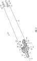
- FIG. 1 shows a diagram of an illustrative cable-driven surgical tool 100 that may incorporate certain principles of the present disclosure.
- Cable-driven surgical tool 100 includes elongate shaft 102, end effector 104 located at a distal end of elongate shaft 102, and housing 108 located at a proximal end of elongate shaft 102.
- Wrist 106 is also located at a distal end of elongate shaft 102 and couples end effector 104 thereto.
- Housing 108 of cable-driven surgical tool 100 may be configured for releasable coupling with a mounting fixture of a robotic manipulator (not shown in FIG.
- housing 108 may be configured for actuating end effector 104 upon engagement by a surgeon or a robotic manipulator. User inputs to housing 108 therefore control operation of end effector 104 via the cables or similar elongate members (obscured in FIG. 1 ).
- housing 108 may be configured for releasable coupling with a mounting fixture of a robotic manipulator.
- Housing 108 may be releasably coupled with the mounting fixture in a variety of ways, such as by clamping or clipping thereto, or slidably mating therewith.
- Illustrative mechanisms for coupling housing 108 to a mounting fixture are described in more detail in U.S. Patent Application Publications 2015/0209965 and 2015/0025549 , and U.S. Patent Application 15/200,283, filed on July 1, 2016 and entitled "Methods, Systems, And Devices For Initializing A Surgical Tool".
- Illustrative robotic surgical systems are also described in these references as well as in U.S. Patent 8,831 782 .
- end effector 104 is configured to move relative to elongate shaft 102 at wrist 106, such as by pivoting at wrist 106, to position end effector 104 at a desired orientation and location relative to a surgical site during a surgical procedure.
- Housing 108 includes various components designed to position and operate various features of end effector 104 (e.g., one or more of clamping, firing, rotation, articulation, energy delivery, and the like).
- one or more cables can extend from housing 108 through wrist 106 to facilitate movement of end effector 104, as discussed in more detail herein.
- elongate shaft 102 and end effector 104 coupled distally thereto are configured to rotate about longitudinal axis A1.
- various components of housing 108 can be configured to facilitate rotational motion of elongate shaft 102 and end effector 104 about longitudinal axis A1.
- elongate shaft 102 may be fixed to housing 108, in which case cable-driven surgical tool 100 may be rotated by the robotic manipulator to reposition elongate shaft 102 and end effector 104.
- Cable-driven surgical tool 100 can be configured to perform at least one surgical function.
- the choice of end effector 104 can determine which surgical function cable-driven surgical tool 100 is able to perform.
- Illustrative configurations of end effector 104 that may be present in cable-driven surgical tool 100 include, for example, forceps, graspers, needle drivers, scissors, electrocauterization tools that apply energy to tissue, staplers, clip appliers, suctioning tools, irrigation tools, imaging devices (e.g., endoscopes or ultrasonic probes), and any combination thereof.
- cable-driven surgical tool 100 may be configured to apply mechanical force to a tissue. The mechanical force can be conveyed via the cables or similar elongate members in mechanical communication with end effector 104.
- Elongate shaft 102 extends distally from housing 108 and has at least one lumen (see FIG. 3 ) extending internally therethrough.
- Elongate shaft 102 may be affixed to housing 108, but alternately may be releasably coupled so as to be interchangeable with other types of shafts, such as shafts have a differing diameter.
- elongate shaft 102 may be rotatably coupled to housing 108.
- End effector 104 can have a variety of sizes, shapes and configurations.
- end effector 104 comprises a tissue grasper or needle driver having opposing jaws 110 and 112 that are configured to move (pivot) between open and closed positions.
- the entirety of end effector 104 may pivot relative to elongate shaft 102 at wrist 106. Pivoting may place end effector 104 in a better position to engage tissue during a surgical procedure.
- the pivoting of end effector 104 may be cable-driven.
- end effector 104 include, but are not limited to, scissors including a pair of opposed cutting jaws, babcocks including a pair of opposed grasping jaws, retractors, and the like. Additional configurations for end effector 104 are also provided above.
- Wrist 106 can likewise have a variety of configurations.
- wrist 106 includes a joint configured to allow movement of end effector 104 relative to elongate shaft 102, such as a pivot joint at which jaws 110 and 112 are pivotally attached.
- Illustrative configurations that may be similar to wrist 106 that are suitable for use in the embodiments of the present disclosure include those described in U.S. Patent Application Publications 2015/0209965 and 2015/0025549 and U.S. Patent Application No. 15/200,283 . Additional discussion of the configuration of wrist 106 and similar wrists is provided hereinbelow in regard to the illustrative embodiments of the present disclosure.
- FIG. 2 shows a diagram illustrating the degrees of freedom through which wrist 106 may articulate. More specifically, the degrees of freedom available to wrist 106 are represented by three translational or position variables (e.g., surge, heave and sway) and three rotational or orientation variables (e.g., Euler angles or roll, pitch and yaw).
- the translational and rotational variables collectively describe the position and orientation of one or more components of a surgical system (e.g., wrist 106 and associated end effector 104) with respect to a given frame of reference, such as a Cartesian coordinate system or spherical coordinate system. As illustrated in FIG.
- the term “surge” refers to forward and backward movement
- the term “heave” refers to up and down movement
- the term “sway” refers to left and right movement.
- roll refers to sideto-side tilting
- pitch refers to forward and backward tilting
- yaw refers to left and right turning.
- a pivoting motion can include pitch movement about a first axis of wrist 106 (e.g., X-axis), yaw movement about a second axis of wrist 106 (e.g., Y-axis), and combinations thereof to allow for 360° rotational movement of end effector 104 about wrist 106.
- a pivoting motion can be limited to movement in a single plane such that end effector 104 rotates only in a single plane (e.g., only pitch movement about a first axis of wrist 106 or only yaw movement about a second axis of wrist 106).
- Cable-driven surgical tool 100 includes a plurality of elongate members (obscured in FIG. 1 and synonymously referred to herein as "cables"), which are configured to impart movement to end effector 104 relative to elongate shaft 102.
- elongate members include, for example, cables, bands, lines, cords, wires, ropes, strings, twisted strings and the like. Cables and similar elongate members can be formed from any of a variety of high-durability materials, such as a metal (e.g., tungsten, stainless steel, and like materials) or a polymer. In at least one embodiment, one or more of the elongate members may be made of a flexible material. Illustrative cables and similar elongate members are described in U.S. Patent Application Publications 2015/0209965 and 2015/0025549 .
- FIGS. 3-5 shows an enlarged view of elongate shaft 102, end effector 104, and wrist 106.
- cable-driven surgical tool 100 includes four cables 302a-d as depicted, one pair being operatively coupled to each of jaws 110 and 112, alternative configurations can have differing numbers of cables or similar elongate members.
- a cable-driven surgical tool having an end effector that does not require internal motion can include two cables or similar elongate members configured to provide articulation upon longitudinal tensioning.
- cables 302a-d extend longitudinally within lumen 305 of elongate shaft 102 through wrist 106 and operably engage end effector 104, as described hereinafter.
- the proximal ends of cables 302a-d are similarly operably engaged with components in housing 108 (not shown in FIG. 3 ).
- the proximal ends of cables 302a-d may operably engage components in housing 108 that are configured for actuation by one or more drive couplers in the mounting fixture of a robotic surgical system.
- One or more of cables 302a-d may be selectively translated longitudinally to cause end effector 104 to move (e.g., pivot in one or more locations) relative to elongate shaft 102.
- one or more of cables 302a-d may translate longitudinally to articulate end effector 104 (e.g., to move jaws 110 and 112 at an angle in a same direction), to open end effector 104 (e.g., to move jaws 110 and 112 away from one another), to close end effector 104 (e.g., to move jaws 110 and 112 toward one other), or any combination thereof.
- cables 302a-d can extend along the exterior of elongate shaft 102, such as in longitudinal channels formed in an exterior surface of elongate shaft 102.
- cables 302a-d are present in matched pairs. Depending on how cables 302a-d are translated longitudinally, the range of degrees of freedom depicted in FIG. 2 can be realized.
- first and third cables 302a and 302c define a first cable loop that proximally engages a first location in housing 108 and distally engages a first component of end effector 104 before looping back to engage a second location in housing 108.
- second and fourth cables 302b and 302d define a second cable loop that proximally engages a third location in housing 108 and distally engages a second component of end effector 104 before looping back to engage a fourth location in housing 108.
- cables 302a/302c and 302b/302d are proximally engaged with separate locations in housing 108 and with separate locations at end effector 104. Double barrel element 132 (see FIGS.
- Suitable means of attachment to double barrel element 132 may include, for example, crimping, welding, adhesive bonding, and the like.
- wrist 106 includes multiple pulleys for engaging and redirecting cables 302a-d during their longitudinal translation.
- wrist 106 includes distal plurality of pulleys 316a, 316b, 318a and 318b, and proximal plurality of pulleys 320a, 320b, 322a and 322b.
- a small gap (best shown in FIG. 4 ) is defined between corresponding pulleys in the distal and proximal pluralities, which is sized for passage of cables 302a-d therethrough.
- Pulleys 316a, 316b, 318a and 318b in the distal plurality of pulleys are mounted to distal wrist axle 308a, and pulleys 320a, 320b, 322a and 322b in the proximal plurality of pulleys are mounted to proximal wrist axle 308b.
- End effector 104 is operably coupled to wrist 106 such that distal wrist axle 308a defines first pivot axis P1 during operation thereof.
- Cable-driven surgical tool 100 further includes second pivot axis P2 along end effector axle 303, about which jaws 110 and 112 of end effector 104 are configured to pivot relative to each other between extremes of open and closed positions, and/or about which jaws 110 and 112 are configured to move together during articulation of end effector 104.
- second pivot axis P2 is substantially perpendicular to longitudinal axis A1.
- axes A1 and P2 may not be precisely perpendicular to one another but nevertheless be considered to be substantially perpendicular due to any number of factors, such as manufacturing tolerance and precision of measurement devices.
- Cable-driven surgical tool 100 has two joints at second pivot axis P2, one joint for each of jaws 110 and 112. Actuation of at least one of cables 302a-d causes movement of jaw 110 and/or jaw 112 at the associated joint(s) along second pivot axis P2.
- jaws 110 and 112 are configured to pivot in tandem at their associated joints. That is, during opening of jaws 110 and 112, each of jaws 110 and 112 rotates at its associated joint, and during closing of jaws 110 and 112, each of jaws 110 and 112 rotates in the opposite direction at its associated joint.
- any of cables 302a-d can compromise the operability of cable-driven surgical tool 100. Even worse, breakage of any of cables 302a-d can render cable-driven surgical tool 100 inoperable. In order to mitigate the risk of cable slackening or breakage during a surgical procedure, it is typical to use cable-driven surgical tool 100 with a generous safety margin of the anticipated operational lifetime of cables 302a-d.
- Cable replacement is accomplished through the incorporation of a releasable interconnect interposed between the distal and proximal ends of a cable or similar elongate member. Incorporation of the releasable interconnect allows the distal end of the cable to be replaced without replacing the proximal end.
- Both cables defining a continuous loop and those being connected by a double barrel element or similar joining element may incorporate releasable interconnects according to the disclosure herein.
- the term "cable system" is used herein to denote a cable or similar elongate member having a distal cable end and a proximal cable end with a releasable interconnect interposed therebetween.
- suitable releasable interconnects may define a male-female joint or coupling, particular examples of which are discussed hereinbelow.
- Cable-driven surgical tools are particularly susceptible to cable damage or failure at this location, especially where the cable bends while engaging the pulleys within a wrist or end effector (e.g., due to material fatigue).
- incorporating a releasable interconnect within a cable system can allow a more robust elongate member to constitute the proximal end of the cable system.
- a cable or similar elongate member of homogeneous character extends between the end effector and the housing
- the necessity for a small cable diameter at the wrist and end effector i.e., the distal cable diameter
- larger-diameter and/or more robust cables or similar elongate members can extend from the releasable interconnect to the housing in order to convey even more durability to the cable-driven surgical tool. That is, in some embodiments, the distal and proximal cable portions of a cable system may comprise different types or diameters of cables. In other embodiments, however, the material and/or diameter in the distal and proximal cable portions of a cable system can be the same. Accordingly, the disclosure herein can allow rapid wrist repair or replacement to take place for providing more reliable tool function.
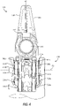
- FIG. 6 is a partial isometric view of illustrative cable-driven surgical tool 600 containing one or more replaceable cable systems.
- Cable-driven surgical tool 600 is similar in some aspects to cable-driven surgical tool 100 and may be better understood with reference to FIGS. 3-5 .
- cable-driven surgical tool 600 includes elongate shaft 602, end effector 604 and wrist 606.
- Cable systems 630a-d extend through lumen 605 and are operatively engaged distally with end effector 604 and proximally within a housing (not shown in FIG. 6 ), thereby allowing manipulation of jaws 610 and 612 to take place.
- wrist 606 includes a distal plurality of pulleys 616 and a proximal plurality of pulleys 620.
- Distal wrist axle 608a and proximal wrist axle 608b correspond to distal and proximal wrist axles 308a and 308b of FIGS. 3-5 .
- end effector axle 603, pivot axes P1 and P2, and longitudinal axis A1 all correspond to like elements described previously.
- Each cable system 630a-d is divided into corresponding distal cable portion 632a-d and proximal cable portion 634a-d, with a corresponding releasable interconnect adjoining distal cable portions 632a-d and proximal cable portions 634a-d at a junction therebetween.
- the releasable interconnects may be arranged at a location between wrist 606 and the housing of cable-driven surgical tool 600.
- Each releasable interconnect includes two connection components configured to mate with one another at the junction in a complementary fashion.
- first connection components 633a-d of the releasable interconnects are located within lumen 605 at the terminus of each of corresponding distal cable portions 632a-d
- second connection components 635a-d of the releasable interconnects are located within lumen 605 at the terminus of each of corresponding proximal cable portions 634a-d.
- FIG. 6 depicts such mating complementarity is intended to illustrate the concepts of the present disclosure and is not necessarily meant to represent functional interconnectivity.
- suitable releasable interconnects are discussed in more detail below.
- suitable releasable interconnects that may adjoin distal cable portions 632a-d to proximal cable portions 634a-d in cable-driven surgical tool 600 include, but are not limited to, male-female threading, bayonet connectors, ball connectors, snap connectors (collars), yin-yang connectors (puzzle piece connectors) and the like. These illustrative releasable interconnects are depicted in greater detail in FIGS. 7A, 7B , 8A, 8B , 9A, 9B , 10A, 10B , 11A and 11B in uncoupled and coupled positions.
- releasable interconnects that may be suitable for use in the embodiments of the present disclosure include, for example, buckles, clamps, hook and eye connectors, cotters, cotter pins, clevis fasteners, snap fasteners, and the like.
- any of the releasable interconnects disclosed herein may be used in particular configurations of cable-driven surgical tool 600.
- the same type of releasable interconnect can be present in each of cable systems 630a-d, or at least one of cable systems 630a-d can contain types of releasable interconnects that differ from one another.
- employing two or more different types of interconnect technologies to form a hybrid releasable interconnect is also possible.
- a ball connector may further employ a cotter pin to fasten the ball and its receptor together more securely.
- FIGS. 7A and 7B show an embodiment of cable systems 630a-d that may be used in cable-driven surgical tool 600 of FIG. 6 . More particularly, cable system 730 may be representative of any of cable systems 630a-d of FIG. 6 in one or more embodiments.
- first connection component 633a and second connection component 635a are provided as male-female threaded adapters or connectors. The male threading and the female threading may reside on either of distal cable portion 632a or proximal cable portion 634a, and the depicted configuration should not be considered as limiting. Furthermore, the threading pitch, lead, angle, and direction may vary from that depicted, and such considerations will be familiar to one having ordinary skill in the art.
- FIGS. 8A and 8B show another embodiment of cable systems 630a-d that may be used in cable-driven surgical tool 600 of FIG. 6 . More particularly, cable system 830 may be representative of any of cable systems 630a-d of FIG. 6 in one or more embodiments.
- first connection component 633a and second connection component 635a are provided as corresponding bayonet connectors.
- the male portion (i.e., first connection component 633a) and the female portion (i.e., second connection component 635a) of the bayonet connector may reside on either of distal cable portion 632a or proximal cable portion 634a, and the depicted configuration should not be considered as limiting.
- the design of the bayonet connector may vary from that depicted, and one having ordinary skill in the art will be able to choose a suitable bayonet connector for a given application.
- FIGS. 9A and 9B show another embodiment of cable systems 630a-d that may be used in cable-driven surgical tool 600 of FIG. 6 . More particularly, cable system 930 may be representative of any of cable systems 630a-d of FIG. 6 in one or more embodiments.
- first connection component 633a and second connection component 635a are provided as corresponding parts of a ball connector. Cable tensioning maintains the ball (i.e., first connection component 633a) within its receptor (i.e., second connection component 635a).
- the ball and the receptor of a ball joint may reside on either of distal cable portion 632a or proximal cable portion 634a, and the depicted configuration and design should not be considered as limiting.
- FIGS. 10A and 10B show another embodiment of cable systems 630a-d that may be used in cable-driven surgical tool 600. More particularly, cable system 1030 may be representative of any of cable systems 630a-d of FIG. 6 in one or more embodiments.
- first connection component 633a and second connection component 635a are provided as corresponding parts of a snap connector (snap collar).
- a flanged stud i.e., first connection component 633a
- a corresponding receptor i.e., second connection component 635a
- Collar 1038 constricts the receptor to hold the inserted flanged stud in place.
- heat shrink tubing or manual crimping may be used interchangeably to hold the flanged study within its corresponding receptor.
- collar 1038 may be omitted if the flanged stud and receptor can be held in place without it.
- the flanged stud and receptor may reside on either of distal cable portion 632a or proximal cable portion 634a, and the depicted configuration and design should not be considered as limiting.
- FIGS. 11A and 11B show another embodiment of cable systems 630a-d that may be used in cable-driven surgical tool 600. More particularly, cable system 1130 may be representative of any of cable systems 630a-d of FIG. 6 in one or more embodiments.
- a yin-yang connector (puzzle-piece connector) defines first complementary component 633a and second complementary component 635a.
- sleeve 1138 is slid over the mated joint to hold the components in place.
- sleeve 1138 may be heat shrink tubing that can be heated and constricted to hold the components in place.
- sleeve 1138 may include, for example, interference fit tubing, crimped tubing, mechanically fastened tubing and the like.
- FIG. 11B shows the disposition of sleeve 1138 prior to sliding over the mated joint.
- sleeve 1138 may be omitted if the mated joint can be held in place without it.
- the depicted configuration and design should not be considered as limiting.
- the relative axial location of the releasable interconnects in cable systems 630a-d with respect to wrist 606 are not particularly limited. However, in some embodiments, it may be more advantageous for the releasable interconnects to be located closer to wrist 606 as opposed to housing 108 ( FIG. 1 ), as the former is where cable wear more commonly occurs. That is, in such embodiments, the releasable interconnects may be axially offset toward the distal end of elongate shaft 602. Releasable interconnects that are located closer to housing 108, however, are also possible without departing from the scope of the disclosure. Furthermore, in some embodiments, all of the releasable interconnects are located at substantially the same axial location within lumen 605, although they may be located at different axial locations in other embodiments.
- Elongate shaft 602 has a distal section and a proximal section that are releasably coupled to one another so as to provide access to the releasable interconnects when opened.
- Suitable mechanisms by which the distal and proximal sections may be releasably coupled together include, for example, a threaded engagement, one or more mechanical fasteners, a compression fit, spring-loaded clips, bayonet-style connectors, oval connectors, snap connectors, the like, and any combination thereof.
- Elongate shaft 602 has a window 670 defined therein in order to provide access to the releasable interconnects within lumen 605.
- window 670 may by obscured during use with a removable cover, such as a sleeve, a panel, a hatch, or the like.
- window 670 may be left open, thereby allowing ongoing access to lumen 605 to be realized, provided that insufflation loss is not an issue.
- the incorporation of a releasable interconnect within a cable system can increase the cable diameter considerably over that of the cable alone at a junction between the distal and proximal cable portions.
- the increased diameter in a cable system can be problematic in some instances.
- the limited clearance between pulleys at the wrist of conventional cable-driven surgical tools particularly the clearance between the distal and proximal plurality of pulleys, can make cable threading problematic when a releasable interconnect is present.
- the inventor also discovered various approaches whereby the clearance in a wrist may be increased temporarily, if needed, to facilitate threading of a replacement cable. Specifically, the inventor discovered ready ways to alter or disassemble a wrist partially to facilitate cable threading.
- the partial disassembly approaches discovered by the inventor are considerably more facile than the complete disassembly required for repair of conventional cable-driven surgical tools.
- the partial disassembly approaches of the present disclosure can also be practiced independently of embodiments incorporating a releasable interconnect as described herein.
- the releasable interconnects interposed in cable systems 630a-d can be problematic when threading distal cable portions 632a-d through the limited space in wrist 606.
- wrist 606 can be partially disassembled readily in order to promote cable threading.
- the partial disassembly approaches disclosed herein may facilitate threading of cable systems containing a releasable interconnect
- the same or similar approaches may also be practiced independently, such as when threading conventional cables and like elongate members.
- the same or similar approaches may be practiced independently in conjunction with exchanging one type of end effector for another after the completion of a surgical procedure.
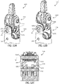
- FIGS. 12A-12C show isometric and cross-sectional views of one approach for generating clearance in a wrist of a cable-driven surgical tool.
- end effector 1204 of surgical tool 1200 is operably connected to wrist 1206 with wrist axle 1250, which defines pivot axis P1.
- wrist axle 1250 which defines pivot axis P1.
- a distal plurality of pulleys 1216 and a proximal plurality of pulleys 1220 are present for guiding cable systems or similar elongate members through wrist 1206.
- Distal plurality of pulleys 1216 are mounted to wrist axle 1250, which simultaneously connects end effector 1204 to wrist 1206 via distal clevis 1240.
- Wrist axle 1260 operably connects proximal plurality of pulleys 1220 to proximal clevis 1270.
- wrist axle 1250 also extends through a pair of pivot discs 1252 (only one shown in FIGS. 12A and 12B ) movably coupled to proximal clevis 1270.
- Each pivot disc 1252 has a centerline that is radially offset from the pivot axis P1.
- pivot axis P1 does not pass through the centerline of pivot discs 1252 (i.e., is eccentric), in contrast to the tool configurations depicted in FIGS 2-6 .
- Pivot discs 1252 are configured for rotation relative to proximal clevis 1270 and may be rotated incrementally to alter the location of pivot axis P1.
- pivot discs 1252 may be rotated with one's fingers, or they may be configured to be rotated using a specialized tool, such as a screwdriver, Allen wrench, or similar tool.
- Pivot discs 1252 may rotate freely or semi-freely in some embodiments. That is, in such embodiments, pivot discs 1252 are not necessarily constrained to just two rotational positions. In other embodiments, pivot discs 1252 may be configured to rotate between a first locked position and a second locked position upon affecting rotational motion.
- first locked position and the second locked position are disposed substantially 180° apart from one another. In other embodiments, the first locked position and the second locked position are between 90° and 180° apart from one another, or between 110° and 180° apart from one another, or between 130° and 180° apart from one another, or between 150° and 180° apart from one another.
- pivot axis P1 is eccentric to the centerline of pivot discs 1252, rotation of pivot discs 1252 correspondingly repositions pivot axis P1. For example, in the case of rotating pivot discs 1252 by 180°, a maximum displacement of pivot axis P1 occurs in rotating from the first position to the second position. Displacement of pivot axis P1 also causes a corresponding displacement in distal plurality of pulleys 1216 and distal clevis 1240, through which wrist axle 1250 passes.
- FIG. 12A shows pivot discs 1252 in a first position, such that pivot axis P1 is situated with distal plurality of pulleys 1216 and proximal plurality of pulleys 1220 in near engagement with one another.
- FIGS. 12B and 12C show pivot discs 1252 in a second position. More specifically, rotation of pivot disc 1252 by 180° moves pivot axis P1 distally, thereby displacing distal clevis 1240 and increasing a separation distance between distal plurality of pulleys 1216 and proximal plurality of pulleys 1220.
- FIGS. 12A and 12B have illustrated a near-180° rotation of pivot disc 1252, it is to be recognized that non-180° rotational angles may also affect sufficient pulley separation and may be employed in the embodiments of the present disclosure.
- pivot discs 1252 may be rotated in the opposite direction to return distal plurality of pulleys 1216 to the first (original) position.
- cable-driven surgical tool 1200 may return to service or undergo recalibration, if neeeded.
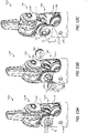
- FIGS. 13A-13C show isometric views of a second approach for generating clearance in a wrist of a cable-driven surgical tool.
- the approach depicted in FIGS. 12A-12C provides for removal of the pivot discs in the course of increasing the separation distance between the distal plurality of pulleys and the proximal plurality of pulleys.
- end effector 1305 is operably connected to wrist 1306 with wrist axle 1350 in cable-driven surgical tool 1300.
- Wrist axle 1350 defines pivot axis P1.
- a distal plurality of pulleys 1316 and a proximal plurality of pulleys 1320 are present for guiding cable systems or similar elongate members through wrist 1306.
- Wrist axle 1350 passes through distal plurality of pulleys 1316 and proximal clevis 1370 in operably connecting end effector 1305 to wrist 1306.
- Wrist axle 1360 operably connects proximal plurality of pulleys 1320 to proximal clevis 1370.
- Wrist axle 1350 extends through pivot discs 1352, which are removably coupled to proximal clevis 1370.
- pivot discs 1352 may be removably coupled to proximal clevis 1370 via threading. In such embodiments, pivot discs 1352 may be rotated clockwise or counterclockwise to affect their removal from proximal clevis 1370. In other embodiments, pivot discs 1352 may be removably coupled to proximal clevis 1370 in a non-threaded manner, such as via a compression fitting, latching mechanism, or the like. In either case, removal of pivot discs 1352 from proximal clevis 1370 may be affected manually, with a tool or combinations thereof. In some instances, pivot discs 1352 may be removed from proximal clevis 1370 without being rotated.
- distal plurality of pulleys 1316 and end effector 1305 Upon removal of pivot discs 1352 from wrist 1306, distal plurality of pulleys 1316 and end effector 1305 remain coupled via wrist axle 1350 but are then free to move with an increased range of motion, either sideto-side or upward with respect to proximal plurality of pulleys 1320.
- end effector 1305, distal plurality of pulleys 1316 and wrist axle 1350 may be moved upwardly to increase the separation between distal plurality of pulleys 1316 and proximal plurality of pulleys 1320.
- end effector 1305, distal plurality of pulleys and wrist axle 1350 may be lowered into their original position, such that the replacement cable properly engages proximal plurality of pulleys 1320.
- Pivot discs 1352 may then be reinserted into proximal clevis 1370 to ready cable-driven surgical tool 1300 for service or recalibration.
- the present disclosure also provides various methods for replacing a cable within a cable-driven surgical tool, such as those disclosed herein.
- Cable replacement can occur at periodic intervals, in response to cable slackening, in response to cable breakage, or any combination thereof. Any or all of the cables within a surgical tool may be replaced at the same time or at different times according to the methods described herein.
- cable replacement methods of the present disclosure may comprise: accessing a plurality of cable systems of a cable-driven surgical tool, each cable system extending with a lumen defined in an elongate shaft and operably engaging an end effector operably coupled to a distal end of the elongate shaft, where each cable system comprises a distal cable portion and a proximal cable portion adjoined by a releasable interconnect and each releasable interconnect comprises a first connection component located at a terminus of the distal cable portion and a second connection component located at a terminus of the proximal cable portion; disconnecting the first connection component from the second connection component of at least one of the plurality of cable systems; removing a disconnected distal cable portion from the cable-driven surgical tool; introducing a replacement distal cable portion also having a first connection component into the cable-driven surgical tool; and mating the first connection component of the replacement distal cable portion to an unmated second complementary component in the lumen.
- Methods of the present disclosure comprise accessing the releasable interconnect by disconnecting a distal section of the elongate shaft of the cable-driven surgical tool from a proximal cable portion of the elongate shaft of the surgical tool. Methods of the present disclosure also comprise accessing the releasable interconnect through a window defined in the elongate shaft of the cable-driven surgical tool.
- the phrase "at least one of” preceding a series of items, with the terms “and” or “or” to separate any of the items, modifies the list as a whole, rather than each member of the list (i.e., each item).
- the phrase "at least one of” allows a meaning that includes at least one of any one of the items, and/or at least one of any combination of the items, and/or at least one of each of the items.
- the phrases “at least one of A, B, and C” or “at least one of A, B, or C” each refer to only A, only B, or only C; any combination of A, B, and C; and/or at least one of each of A, B, and C.
Landscapes
- Health & Medical Sciences (AREA)
- Surgery (AREA)
- Life Sciences & Earth Sciences (AREA)
- Engineering & Computer Science (AREA)
- Medical Informatics (AREA)
- Biomedical Technology (AREA)
- Heart & Thoracic Surgery (AREA)
- Nuclear Medicine, Radiotherapy & Molecular Imaging (AREA)
- Molecular Biology (AREA)
- Animal Behavior & Ethology (AREA)
- General Health & Medical Sciences (AREA)
- Public Health (AREA)
- Veterinary Medicine (AREA)
- Robotics (AREA)
- Pathology (AREA)
- Surgical Instruments (AREA)
Description
- Minimally invasive surgical (MIS) tools and procedures can often be preferred over traditional open surgical techniques due to their ability to decrease post-operative recovery time and to leave minimal scarring. Laparoscopic surgery is one type of MIS procedure in which one or more small incisions are formed in the abdomen of a patient and a trocar is inserted through each incision to provide a surgical access pathway for an appropriate surgical tool. Trocars can additionally provide an internal seal assembly for maintaining insufflation of the abdomen during a surgical procedure.
- A variety of MIS tools can be inserted into the abdominal cavity of a patient via a trocar and maneuvered from outside the abdomen. Laparoscopic surgical tools, for example, are often similar to those used in traditional surgical procedures, with the exception that laparoscopic surgical tools possess an elongate shaft extending from an end effector to a location outside the abdomen. The end effector is the surgically functional part of the surgical tool. The shaft protrudes externally through a trocar when the surgical tool is inserted in the abdomen of a patient, and an external portion of the surgical tool provides a means for manipulating and communicating with the end effector. Once inserted in a patient's body, the end effector can engage and/or treat tissue in a number of ways to achieve a desired diagnostic or therapeutic effect. Illustrative end effectors of laparoscopic and similar surgical tools include, but are not limited to, scissors, graspers, needle drivers, clamps, staplers, cauterizers, suction tools, irrigation tools, clip-appliers, and the like.
- Robotic surgery represents a specialized class of laparoscopic surgical procedures. Instead of directly engaging a surgical tool, as in traditional laparoscopic surgery, a surgeon instead manipulates and engages the surgical tool using an electronic interface communicatively coupled to a robotic manipulator. Manipulation and engagement of a surgical tool under robotic control can allow much more precise surgical procedures to be performed in many instances. A surgeon need not necessarily even be in the operating room with the patient. Advantageously, robotic surgical systems can allow intuitive hand movements to be realized by maintaining a natural eye-hand axis. In addition, robotic surgical systems can incorporate a "wrist" at the end effector to provide natural, hand-like articulation during a robotic surgical procedure. The wrist can also facilitate an expanded and more complex range of motion than is possible with a human wrist, which can allow highly elaborate and precise surgical procedures to be performed.
- In robotic surgery, one or more arms of a robotic manipulator are mounted to corresponding surgical tools, and the tool(s) is/are manipulated and engaged under the direction of a surgeon during a surgical procedure. Each arm has one or more joints to facilitate manipulation of its attached surgical tool and a mounting fixture to promote the tool's attachment with a complementary housing at the proximal end of the tool. The housing includes one or more mechanisms for actuating the end effector, such as a system for instigating movement of the end effector upon a suitable input from the mounting fixture. For example, the mounting fixture may include one or more drive couplers (e.g., rotary or linear drive couplers) configured to engage a suitable component in the housing and produce a corresponding motion in the end effector (e.g., rotation, pitch, yaw or actuation).
- Most conventional laparoscopic surgical tools, including robotic surgical tools, employ multiple elongate members that pass through the elongate shaft within a lumen and establish mechanical communication between the mechanism in the housing and the end effector. Specifically, in many instances, the elongate members deploy or retract in response to a mechanical input from the mounting fixture and housing to convey surgical instructions to the end effector. Illustrative elongate members within laparoscopic and similar surgical tools include, for example, high-durability cables, bands, lines, cords, wires, ropes, strings, twisted strings or like structures that extend continuously from the housing to the end effector. These and similar elongate members are collectively referred to herein as "cables". Similarly, surgical tools containing such cables may be referred to herein as "cable-driven surgical tools."
- One drawback of laparoscopic and similar cable-driven surgical tools is that their cables are prone to weakening (fatigue) and wear over time, especially where the cables interact with the end effector and are forced into curved shapes (e.g., where contacting internal pulleys). Cable weakening can lead to slackening, which may lessen the end effector's movement precision and possibly compromise the safety and effectiveness of a surgical procedure. Further cable slackening can lead to derailment from the mechanism within the housing or elsewhere. Extreme cable weakening can even lead to catastrophic cable failure (breakage) in some instances. As a result, laparoscopic and similar cable-driven surgical tools are commonly taken out of service well in advance of the time at which cable weakening and wear are anticipated to become problematic.
- Once a conventional laparoscopic or similar cable-driven surgical tool is taken out of service due to cable weakening and wear, there is usually no way to recondition the tool effectively without disassembling it nearly completely. In many cases, conventional laparoscopic and similar cable-driven surgical tools may be discarded once taken out of service due to the difficulty of disassembly and refurbishment, despite many of the other tool components remaining within their usable lifetimes.
US 2012/123200 A1 discloses a surgical device that includes a first cable portion that engages a first component such that a first friction exists between the first cable portion and the first component. The surgical device includes a second cable portion having a first end operatively coupled to a first end of the first cable portion. The second cable portion engages a second component such that a second friction exists between the second cable portion and the second component, such that the second friction is greater than the first friction. - The following figures are included to illustrate certain aspects of the present disclosure, and should not be viewed as exclusive embodiments. The subject matter disclosed is capable of considerable modifications, alterations, combinations, and equivalents in form and function, without departing from the scope of the invention as defined in the appended claims.
-
FIG. 1 shows a diagram of an illustrative cable-driven surgical tool that may incorporate certain principles of the present disclosure. -
FIG. 2 shows a diagram illustrating the degrees of freedom through which a wrist of a surgical tool may articulate. -
FIGS. 3-5 show various views of an illustrative cable-driven surgical tool. -
FIG. 6 shows a diagram illustrating a cable-driven surgical tool containing one or more replaceable cable systems. -
FIGS. 7A, 7B ,8A, 8B ,9A, 9B ,10A, 10B ,11A and 11B show several views of various releasable interconnects in uncoupled and coupled positions. -
FIGS. 12A-C show diagrams illustrating one approach for generating clearance in a wrist of a cable-driven surgical tool. -
FIGS. 13A-13C show diagrams illustrating a second approach for generating clearance in a wrist of a cable-driven surgical tool. - The present disclosure generally describes cable-driven surgical tools and, more specifically, cable-driven surgical tools in which the distal end of one or more cables can be readily replaced.
- As discussed above, cable weakening and wear commonly occur in cable-driven surgical tools. Worn or broken cables can be very difficult to replace in conventional cable-driven surgical tools. At present, discarding a cable-driven surgical tool with worn or broken cables may be preferable to attempting its refurbishment. Advantageously, the present disclosure provides cable-driven surgical tools and methods in which the cables and similar elongate members can be readily replaced. More specific advantages are discussed hereinbelow.
- Before discussing how the present disclosure addresses the issue of cable replacement in cable-driven surgical tools, a brief overview of conventional cable-driven surgical tools will be provided hereinafter in order for the embodiments of the present disclosure to be better understood. Many of the concepts and features discussed hereinafter are also applicable to the cable-driven surgical tools and methods of the present disclosure. The cable-driven surgical tools of the present disclosure may be configured as robotic surgical tools (i.e., by being compatible with the mounting fixture of a robotic manipulator), although they may be configured as conventional laparoscopic surgical tools in alternative embodiments (i.e., by being capable of direct engagement by a surgeon).
- The terms "proximal" and "distal" are defined herein relative to the location of engagement by a surgeon or a robotic manipulator. The term "proximal" refers to a position closer to the location of engagement, and the term "distal" refers to a position more removed from the location of engagement. Moreover, directional terms such as above, below, upper, lower, upward, downward, left, right, and the like are used to describe relative position in the figures and thus should not be considered limiting.
-
FIG. 1 shows a diagram of an illustrative cable-drivensurgical tool 100 that may incorporate certain principles of the present disclosure. Cable-drivensurgical tool 100 includeselongate shaft 102,end effector 104 located at a distal end ofelongate shaft 102, andhousing 108 located at a proximal end ofelongate shaft 102.Wrist 106 is also located at a distal end ofelongate shaft 102 andcouples end effector 104 thereto.Housing 108 of cable-drivensurgical tool 100 may be configured for releasable coupling with a mounting fixture of a robotic manipulator (not shown inFIG. 1 ), alternately referred to as a "robot" or "surgical robot." In some alternative embodiments,housing 108 may be configured for actuatingend effector 104 upon engagement by a surgeon or a robotic manipulator. User inputs tohousing 108 therefore control operation ofend effector 104 via the cables or similar elongate members (obscured inFIG. 1 ). - In one or more embodiments,
housing 108 may be configured for releasable coupling with a mounting fixture of a robotic manipulator.Housing 108 may be releasably coupled with the mounting fixture in a variety of ways, such as by clamping or clipping thereto, or slidably mating therewith. Illustrative mechanisms for couplinghousing 108 to a mounting fixture are described in more detail inU.S. Patent Application Publications 2015/0209965 and2015/0025549 , andU.S. Patent Application 15/200,283, filed on July 1, 2016 U.S. Patent 8,831 782 . - Continuing with
FIG. 1 ,end effector 104 is configured to move relative to elongateshaft 102 atwrist 106, such as by pivoting atwrist 106, to positionend effector 104 at a desired orientation and location relative to a surgical site during a surgical procedure.Housing 108 includes various components designed to position and operate various features of end effector 104 (e.g., one or more of clamping, firing, rotation, articulation, energy delivery, and the like). In illustrative embodiments, one or more cables (obscured inFIG. 1 ) can extend fromhousing 108 throughwrist 106 to facilitate movement ofend effector 104, as discussed in more detail herein. In at least some embodiments,elongate shaft 102 andend effector 104 coupled distally thereto are configured to rotate about longitudinal axis A1. In some embodiments, various components ofhousing 108 can be configured to facilitate rotational motion ofelongate shaft 102 andend effector 104 about longitudinal axis A1. In other embodiments,elongate shaft 102 may be fixed tohousing 108, in which case cable-drivensurgical tool 100 may be rotated by the robotic manipulator to repositionelongate shaft 102 andend effector 104. - Cable-driven
surgical tool 100, particularly atend effector 104, can be configured to perform at least one surgical function. The choice ofend effector 104 can determine which surgical function cable-drivensurgical tool 100 is able to perform. Illustrative configurations ofend effector 104 that may be present in cable-drivensurgical tool 100 include, for example, forceps, graspers, needle drivers, scissors, electrocauterization tools that apply energy to tissue, staplers, clip appliers, suctioning tools, irrigation tools, imaging devices (e.g., endoscopes or ultrasonic probes), and any combination thereof. In at least one embodiment, cable-drivensurgical tool 100 may be configured to apply mechanical force to a tissue. The mechanical force can be conveyed via the cables or similar elongate members in mechanical communication withend effector 104. -
Elongate shaft 102 extends distally fromhousing 108 and has at least one lumen (seeFIG. 3 ) extending internally therethrough.Elongate shaft 102 may be affixed tohousing 108, but alternately may be releasably coupled so as to be interchangeable with other types of shafts, such as shafts have a differing diameter. In at least some embodiments,elongate shaft 102 may be rotatably coupled tohousing 108. -
End effector 104 can have a variety of sizes, shapes and configurations. In the illustrative configuration ofFIG. 1 ,end effector 104 comprises a tissue grasper or needle driver having opposingjaws end effector 104 may pivot relative to elongateshaft 102 atwrist 106. Pivoting may placeend effector 104 in a better position to engage tissue during a surgical procedure. The pivoting ofend effector 104 may be cable-driven. Other suitable cable-driven configurations forend effector 104 include, but are not limited to, scissors including a pair of opposed cutting jaws, babcocks including a pair of opposed grasping jaws, retractors, and the like. Additional configurations forend effector 104 are also provided above. -
Wrist 106 can likewise have a variety of configurations. In the illustrative configuration ofFIG. 1 ,wrist 106 includes a joint configured to allow movement ofend effector 104 relative to elongateshaft 102, such as a pivot joint at whichjaws wrist 106 that are suitable for use in the embodiments of the present disclosure include those described inU.S. Patent Application Publications 2015/0209965 and2015/0025549 andU.S. Patent Application No. 15/200,283 . Additional discussion of the configuration ofwrist 106 and similar wrists is provided hereinbelow in regard to the illustrative embodiments of the present disclosure. -
FIG. 2 shows a diagram illustrating the degrees of freedom through whichwrist 106 may articulate. More specifically, the degrees of freedom available towrist 106 are represented by three translational or position variables (e.g., surge, heave and sway) and three rotational or orientation variables (e.g., Euler angles or roll, pitch and yaw). The translational and rotational variables collectively describe the position and orientation of one or more components of a surgical system (e.g.,wrist 106 and associated end effector 104) with respect to a given frame of reference, such as a Cartesian coordinate system or spherical coordinate system. As illustrated inFIG. 2 , the term "surge" refers to forward and backward movement, the term "heave" refers to up and down movement, and the term "sway" refers to left and right movement. With regard to the rotational terms inFIG. 2 , "roll" refers to sideto-side tilting, "pitch" refers to forward and backward tilting, and "yaw" refers to left and right turning. - In some embodiments, a pivoting motion can include pitch movement about a first axis of wrist 106 (e.g., X-axis), yaw movement about a second axis of wrist 106 (e.g., Y-axis), and combinations thereof to allow for 360° rotational movement of
end effector 104 aboutwrist 106. In other embodiments, a pivoting motion can be limited to movement in a single plane such thatend effector 104 rotates only in a single plane (e.g., only pitch movement about a first axis ofwrist 106 or only yaw movement about a second axis of wrist 106). - Cable-driven
surgical tool 100 includes a plurality of elongate members (obscured inFIG. 1 and synonymously referred to herein as "cables"), which are configured to impart movement to endeffector 104 relative to elongateshaft 102. Illustrative forms of the elongate members include, for example, cables, bands, lines, cords, wires, ropes, strings, twisted strings and the like. Cables and similar elongate members can be formed from any of a variety of high-durability materials, such as a metal (e.g., tungsten, stainless steel, and like materials) or a polymer. In at least one embodiment, one or more of the elongate members may be made of a flexible material. Illustrative cables and similar elongate members are described inU.S. Patent Application Publications 2015/0209965 and2015/0025549 . - The disposition of cables and similar elongate members within cable-driven
surgical tool 100 is illustrated more fully inFIGS. 3-5 , which shows an enlarged view ofelongate shaft 102,end effector 104, andwrist 106. Although cable-drivensurgical tool 100 includes fourcables 302a-d as depicted, one pair being operatively coupled to each ofjaws - As shown in
FIGS. 3-5 ,cables 302a-d extend longitudinally withinlumen 305 ofelongate shaft 102 throughwrist 106 and operably engageend effector 104, as described hereinafter. The proximal ends ofcables 302a-d are similarly operably engaged with components in housing 108 (not shown inFIG. 3 ). For example, the proximal ends ofcables 302a-d may operably engage components inhousing 108 that are configured for actuation by one or more drive couplers in the mounting fixture of a robotic surgical system. One or more ofcables 302a-d may be selectively translated longitudinally to causeend effector 104 to move (e.g., pivot in one or more locations) relative to elongateshaft 102. Depending on the required motion, one or more ofcables 302a-d may translate longitudinally to articulate end effector 104 (e.g., to movejaws jaws jaws - Although a
single lumen 305 is depicted inFIG. 3 , multiple lumens can be present in alternative embodiments, such that one or more ofcables 302a-d is housed within each of the multiple lumens. In further alternate embodiments,cables 302a-d can extend along the exterior ofelongate shaft 102, such as in longitudinal channels formed in an exterior surface ofelongate shaft 102. - In the illustrative configuration of
FIG. 3 ,cables 302a-d are present in matched pairs. Depending on howcables 302a-d are translated longitudinally, the range of degrees of freedom depicted inFIG. 2 can be realized. - In some embodiments, first and
third cables housing 108 and distally engages a first component ofend effector 104 before looping back to engage a second location inhousing 108. Similarly, in such embodiments, second andfourth cables housing 108 and distally engages a second component ofend effector 104 before looping back to engage a fourth location inhousing 108. In other embodiments,cables 302a/302c and 302b/302d are proximally engaged with separate locations inhousing 108 and with separate locations atend effector 104. Double barrel element 132 (seeFIGS. 4 and5 ) may bridge the discontinuity betweencables cables barrel element 132 may include, for example, crimping, welding, adhesive bonding, and the like. - Referring still to
FIG. 3 , and with further reference toFIGS. 4 and5 ,wrist 106 includes multiple pulleys for engaging and redirectingcables 302a-d during their longitudinal translation. Specifically,wrist 106 includes distal plurality of pulleys 316a, 316b, 318a and 318b, and proximal plurality of pulleys 320a, 320b, 322a and 322b. A small gap (best shown inFIG. 4 ) is defined between corresponding pulleys in the distal and proximal pluralities, which is sized for passage ofcables 302a-d therethrough.Pulleys distal wrist axle 308a, andpulleys proximal wrist axle 308b.End effector 104 is operably coupled towrist 106 such thatdistal wrist axle 308a defines first pivot axis P1 during operation thereof. - Cable-driven
surgical tool 100 further includes second pivot axis P2 alongend effector axle 303, about whichjaws end effector 104 are configured to pivot relative to each other between extremes of open and closed positions, and/or about whichjaws end effector 104. As illustrated, second pivot axis P2 is substantially perpendicular to longitudinal axis A1. A person having ordinary skill in the art will appreciate that axes A1 and P2 may not be precisely perpendicular to one another but nevertheless be considered to be substantially perpendicular due to any number of factors, such as manufacturing tolerance and precision of measurement devices. - Cable-driven
surgical tool 100 has two joints at second pivot axis P2, one joint for each ofjaws cables 302a-d causes movement ofjaw 110 and/orjaw 112 at the associated joint(s) along second pivot axis P2. In an exemplary embodiment,jaws jaws jaws jaws jaws - As indicated above, slackening of any of
cables 302a-d can compromise the operability of cable-drivensurgical tool 100. Even worse, breakage of any ofcables 302a-d can render cable-drivensurgical tool 100 inoperable. In order to mitigate the risk of cable slackening or breakage during a surgical procedure, it is typical to use cable-drivensurgical tool 100 with a generous safety margin of the anticipated operational lifetime ofcables 302a-d. - As discussed above, it can be difficult to affect cable replacement in conventional cable-driven surgical tools, such as those depicted illustratively in
FIGS. 1 and3-5 . Conventional surgical tools must be essentially disassembled in order to return them to service, if not outright discarded, even though most other components are still within their operational lifetimes. According to various embodiments of the present disclosure, broken, slackened or damaged cables or similar elongate members may be replaced without disassembling the entirety of a cable-driven surgical tool. - Cable replacement is accomplished through the incorporation of a releasable interconnect interposed between the distal and proximal ends of a cable or similar elongate member. Incorporation of the releasable interconnect allows the distal end of the cable to be replaced without replacing the proximal end. Both cables defining a continuous loop and those being connected by a double barrel element or similar joining element may incorporate releasable interconnects according to the disclosure herein. The term "cable system" is used herein to denote a cable or similar elongate member having a distal cable end and a proximal cable end with a releasable interconnect interposed therebetween. Use of the term "cable system" does not necessarily imply that other types of elongate members cannot be employed in a similar manner. In illustrative embodiments, suitable releasable interconnects may define a male-female joint or coupling, particular examples of which are discussed hereinbelow.
- Replacement of the distal end of a cable system may be advantageous. Cable-driven surgical tools are particularly susceptible to cable damage or failure at this location, especially where the cable bends while engaging the pulleys within a wrist or end effector (e.g., due to material fatigue). The limited space in this region, and within cable-driven surgical tools as a whole, limits the cable diameter, which can exacerbate this issue.
- Further advantageously, incorporating a releasable interconnect within a cable system can allow a more robust elongate member to constitute the proximal end of the cable system. In conventional cable-driven surgical tools, wherein a cable or similar elongate member of homogeneous character extends between the end effector and the housing, the necessity for a small cable diameter at the wrist and end effector (i.e., the distal cable diameter) similarly limits the proximal cable diameter at the housing. Although not especially spacious, there is commonly more space available in the housing for cable passage than at the distal end of a conventional cable-driven surgical tool. As such, in some embodiments, larger-diameter and/or more robust cables or similar elongate members can extend from the releasable interconnect to the housing in order to convey even more durability to the cable-driven surgical tool. That is, in some embodiments, the distal and proximal cable portions of a cable system may comprise different types or diameters of cables. In other embodiments, however, the material and/or diameter in the distal and proximal cable portions of a cable system can be the same. Accordingly, the disclosure herein can allow rapid wrist repair or replacement to take place for providing more reliable tool function.
-
FIG. 6 is a partial isometric view of illustrative cable-drivensurgical tool 600 containing one or more replaceable cable systems. Cable-drivensurgical tool 600 is similar in some aspects to cable-drivensurgical tool 100 and may be better understood with reference toFIGS. 3-5 . As shown inFIG. 6 , cable-drivensurgical tool 600 includeselongate shaft 602,end effector 604 andwrist 606.Cable systems 630a-d extend throughlumen 605 and are operatively engaged distally withend effector 604 and proximally within a housing (not shown inFIG. 6 ), thereby allowing manipulation ofjaws FIGS. 3-5 , the number and configuration ofcable systems 630a-d depicted inFIG. 6 are exemplary and nonlimiting. Likewise,wrist 606 includes a distal plurality ofpulleys 616 and a proximal plurality ofpulleys 620.Distal wrist axle 608a andproximal wrist axle 608b correspond to distal andproximal wrist axles FIGS. 3-5 . Similarly,end effector axle 603, pivot axes P1 and P2, and longitudinal axis A1 all correspond to like elements described previously. - Each
cable system 630a-d is divided into correspondingdistal cable portion 632a-d andproximal cable portion 634a-d, with a corresponding releasable interconnect adjoiningdistal cable portions 632a-d andproximal cable portions 634a-d at a junction therebetween. As illustrated, the releasable interconnects may be arranged at a location betweenwrist 606 and the housing of cable-drivensurgical tool 600. Each releasable interconnect includes two connection components configured to mate with one another at the junction in a complementary fashion. As such,first connection components 633a-d of the releasable interconnects are located withinlumen 605 at the terminus of each of correspondingdistal cable portions 632a-d, andsecond connection components 635a-d of the releasable interconnects are located withinlumen 605 at the terminus of each of correspondingproximal cable portions 634a-d. The manner in whichFIG. 6 depicts such mating complementarity is intended to illustrate the concepts of the present disclosure and is not necessarily meant to represent functional interconnectivity. Particular examples of suitable releasable interconnects are discussed in more detail below. - In illustrative embodiments, suitable releasable interconnects that may adjoin
distal cable portions 632a-d toproximal cable portions 634a-d in cable-drivensurgical tool 600 include, but are not limited to, male-female threading, bayonet connectors, ball connectors, snap connectors (collars), yin-yang connectors (puzzle piece connectors) and the like. These illustrative releasable interconnects are depicted in greater detail inFIGS. 7A, 7B ,8A, 8B ,9A, 9B ,10A, 10B ,11A and 11B in uncoupled and coupled positions. Other types of releasable interconnects that may be suitable for use in the embodiments of the present disclosure include, for example, buckles, clamps, hook and eye connectors, cotters, cotter pins, clevis fasteners, snap fasteners, and the like. - Any of the releasable interconnects disclosed herein may be used in particular configurations of cable-driven
surgical tool 600. The same type of releasable interconnect can be present in each ofcable systems 630a-d, or at least one ofcable systems 630a-d can contain types of releasable interconnects that differ from one another. Furthermore, employing two or more different types of interconnect technologies to form a hybrid releasable interconnect is also possible. For example, a ball connector may further employ a cotter pin to fasten the ball and its receptor together more securely. -
FIGS. 7A and 7B show an embodiment ofcable systems 630a-d that may be used in cable-drivensurgical tool 600 ofFIG. 6 . More particularly,cable system 730 may be representative of any ofcable systems 630a-d ofFIG. 6 in one or more embodiments. Referring toFIGS. 7A and 7B ,first connection component 633a andsecond connection component 635a are provided as male-female threaded adapters or connectors. The male threading and the female threading may reside on either ofdistal cable portion 632a orproximal cable portion 634a, and the depicted configuration should not be considered as limiting. Furthermore, the threading pitch, lead, angle, and direction may vary from that depicted, and such considerations will be familiar to one having ordinary skill in the art. -
FIGS. 8A and 8B show another embodiment ofcable systems 630a-d that may be used in cable-drivensurgical tool 600 ofFIG. 6 . More particularly,cable system 830 may be representative of any ofcable systems 630a-d ofFIG. 6 in one or more embodiments. Referring toFIGS. 8A and 8B ,first connection component 633a andsecond connection component 635a are provided as corresponding bayonet connectors. As with male-female threading, the male portion (i.e.,first connection component 633a) and the female portion (i.e.,second connection component 635a) of the bayonet connector may reside on either ofdistal cable portion 632a orproximal cable portion 634a, and the depicted configuration should not be considered as limiting. Furthermore, the design of the bayonet connector may vary from that depicted, and one having ordinary skill in the art will be able to choose a suitable bayonet connector for a given application. -
FIGS. 9A and 9B show another embodiment ofcable systems 630a-d that may be used in cable-drivensurgical tool 600 ofFIG. 6 . More particularly,cable system 930 may be representative of any ofcable systems 630a-d ofFIG. 6 in one or more embodiments. Referring toFIGS. 9A and 9B ,first connection component 633a andsecond connection component 635a are provided as corresponding parts of a ball connector. Cable tensioning maintains the ball (i.e.,first connection component 633a) within its receptor (i.e.,second connection component 635a). As with other types of releasable interconnects, the ball and the receptor of a ball joint may reside on either ofdistal cable portion 632a orproximal cable portion 634a, and the depicted configuration and design should not be considered as limiting. -
FIGS. 10A and 10B show another embodiment ofcable systems 630a-d that may be used in cable-drivensurgical tool 600. More particularly,cable system 1030 may be representative of any ofcable systems 630a-d ofFIG. 6 in one or more embodiments. Referring toFIGS. 10A and 10B ,first connection component 633a andsecond connection component 635a are provided as corresponding parts of a snap connector (snap collar). In the depicted embodiment, a flanged stud (i.e.,first connection component 633a) mates with a corresponding receptor (i.e.,second connection component 635a), andcollar 1038 is then moved (slid) over the mated joint to hold the components in place, as shown in cutaway inFIG. 10B .Collar 1038 constricts the receptor to hold the inserted flanged stud in place. Alternately, heat shrink tubing or manual crimping, for example, may be used interchangeably to hold the flanged study within its corresponding receptor. In some embodiments, however,collar 1038 may be omitted if the flanged stud and receptor can be held in place without it. As with other types of releasable interconnects, the flanged stud and receptor may reside on either ofdistal cable portion 632a orproximal cable portion 634a, and the depicted configuration and design should not be considered as limiting. -
FIGS. 11A and 11B show another embodiment ofcable systems 630a-d that may be used in cable-drivensurgical tool 600. More particularly,cable system 1130 may be representative of any ofcable systems 630a-d ofFIG. 6 in one or more embodiments. Referring toFIGS. 11A and 11B , a yin-yang connector (puzzle-piece connector) defines firstcomplementary component 633a and secondcomplementary component 635a. In this case, once the puzzle-like pieces are mated together to define a joint,sleeve 1138 is slid over the mated joint to hold the components in place. In some embodiments,sleeve 1138 may be heat shrink tubing that can be heated and constricted to hold the components in place. Other suitable configurations forsleeve 1138 may include, for example, interference fit tubing, crimped tubing, mechanically fastened tubing and the like.FIG. 11B shows the disposition ofsleeve 1138 prior to sliding over the mated joint. Still further alternately,sleeve 1138 may be omitted if the mated joint can be held in place without it. As with other types of releasable interconnects, the depicted configuration and design should not be considered as limiting. - Referring again to
FIG. 6 , the relative axial location of the releasable interconnects incable systems 630a-d with respect towrist 606 are not particularly limited. However, in some embodiments, it may be more advantageous for the releasable interconnects to be located closer towrist 606 as opposed to housing 108 (FIG. 1 ), as the former is where cable wear more commonly occurs. That is, in such embodiments, the releasable interconnects may be axially offset toward the distal end ofelongate shaft 602. Releasable interconnects that are located closer tohousing 108, however, are also possible without departing from the scope of the disclosure. Furthermore, in some embodiments, all of the releasable interconnects are located at substantially the same axial location withinlumen 605, although they may be located at different axial locations in other embodiments. - Regardless of the axial position of the releasable interconnects within
lumen 605, a suitable route for accessing the releasable interconnects from the exterior ofelongate shaft 602 is provided. Sealing in proximity to the access location to lumen 605 can be provided, if needed, to aid in maintaining insufflation, for example, according to some embodiments.Elongate shaft 602 has a distal section and a proximal section that are releasably coupled to one another so as to provide access to the releasable interconnects when opened. Suitable mechanisms by which the distal and proximal sections may be releasably coupled together include, for example, a threaded engagement, one or more mechanical fasteners, a compression fit, spring-loaded clips, bayonet-style connectors, oval connectors, snap connectors, the like, and any combination thereof.Elongate shaft 602 has awindow 670 defined therein in order to provide access to the releasable interconnects withinlumen 605. In some embodiments,window 670 may by obscured during use with a removable cover, such as a sleeve, a panel, a hatch, or the like. In other embodiments,window 670 may be left open, thereby allowing ongoing access tolumen 605 to be realized, provided that insufflation loss is not an issue. - The incorporation of a releasable interconnect within a cable system can increase the cable diameter considerably over that of the cable alone at a junction between the distal and proximal cable portions. The increased diameter in a cable system can be problematic in some instances. Specifically, the limited clearance between pulleys at the wrist of conventional cable-driven surgical tools, particularly the clearance between the distal and proximal plurality of pulleys, can make cable threading problematic when a releasable interconnect is present.
- As such, the inventor also discovered various approaches whereby the clearance in a wrist may be increased temporarily, if needed, to facilitate threading of a replacement cable. Specifically, the inventor discovered ready ways to alter or disassemble a wrist partially to facilitate cable threading. The partial disassembly approaches discovered by the inventor are considerably more facile than the complete disassembly required for repair of conventional cable-driven surgical tools. Furthermore, the partial disassembly approaches of the present disclosure can also be practiced independently of embodiments incorporating a releasable interconnect as described herein.
- The releasable interconnects interposed in
cable systems 630a-d can be problematic when threadingdistal cable portions 632a-d through the limited space inwrist 606. To address this issue, the inventor also developed several approaches for temporarily increasing the clearance inwrist 606 to facilitate cable threading between the distal and proximal pluralities of pulleys. Specifically, in various embodiments of the present disclosure,wrist 606 can be partially disassembled readily in order to promote cable threading. Although the partial disassembly approaches disclosed herein may facilitate threading of cable systems containing a releasable interconnect, the same or similar approaches may also be practiced independently, such as when threading conventional cables and like elongate members. Furthermore, in some or other embodiments, the same or similar approaches may be practiced independently in conjunction with exchanging one type of end effector for another after the completion of a surgical procedure. -
FIGS. 12A-12C show isometric and cross-sectional views of one approach for generating clearance in a wrist of a cable-driven surgical tool. As shown inFIG. 12A ,end effector 1204 ofsurgical tool 1200 is operably connected towrist 1206 withwrist axle 1250, which defines pivot axis P1. As best shown inFIG. 12C , a distal plurality ofpulleys 1216 and a proximal plurality ofpulleys 1220 are present for guiding cable systems or similar elongate members throughwrist 1206. Distal plurality ofpulleys 1216 are mounted towrist axle 1250, which simultaneously connectsend effector 1204 towrist 1206 viadistal clevis 1240.Wrist axle 1260 operably connects proximal plurality ofpulleys 1220 toproximal clevis 1270. - As illustrated,
wrist axle 1250 also extends through a pair of pivot discs 1252 (only one shown inFIGS. 12A and 12B ) movably coupled toproximal clevis 1270. Eachpivot disc 1252 has a centerline that is radially offset from the pivot axis P1. Thus, pivot axis P1 does not pass through the centerline of pivot discs 1252 (i.e., is eccentric), in contrast to the tool configurations depicted inFIGS 2-6 . -
Pivot discs 1252 are configured for rotation relative toproximal clevis 1270 and may be rotated incrementally to alter the location of pivot axis P1. In some embodiments,pivot discs 1252 may be rotated with one's fingers, or they may be configured to be rotated using a specialized tool, such as a screwdriver, Allen wrench, or similar tool.Pivot discs 1252 may rotate freely or semi-freely in some embodiments. That is, in such embodiments,pivot discs 1252 are not necessarily constrained to just two rotational positions. In other embodiments,pivot discs 1252 may be configured to rotate between a first locked position and a second locked position upon affecting rotational motion. In exemplary embodiments, the first locked position and the second locked position are disposed substantially 180° apart from one another. In other embodiments, the first locked position and the second locked position are between 90° and 180° apart from one another, or between 110° and 180° apart from one another, or between 130° and 180° apart from one another, or between 150° and 180° apart from one another. - Since pivot axis P1 is eccentric to the centerline of
pivot discs 1252, rotation ofpivot discs 1252 correspondingly repositions pivot axis P1. For example, in the case ofrotating pivot discs 1252 by 180°, a maximum displacement of pivot axis P1 occurs in rotating from the first position to the second position. Displacement of pivot axis P1 also causes a corresponding displacement in distal plurality ofpulleys 1216 anddistal clevis 1240, through whichwrist axle 1250 passes. -
FIG. 12A showspivot discs 1252 in a first position, such that pivot axis P1 is situated with distal plurality ofpulleys 1216 and proximal plurality ofpulleys 1220 in near engagement with one another.FIGS. 12B and 12C showpivot discs 1252 in a second position. More specifically, rotation ofpivot disc 1252 by 180° moves pivot axis P1 distally, thereby displacingdistal clevis 1240 and increasing a separation distance between distal plurality ofpulleys 1216 and proximal plurality ofpulleys 1220. AlthoughFIGS. 12A and 12B have illustrated a near-180° rotation ofpivot disc 1252, it is to be recognized that non-180° rotational angles may also affect sufficient pulley separation and may be employed in the embodiments of the present disclosure. - Once
wrist 1206 has been threaded to load the distal cable portion of a replacement cable,pivot discs 1252 may be rotated in the opposite direction to return distal plurality ofpulleys 1216 to the first (original) position. At this point, cable-drivensurgical tool 1200 may return to service or undergo recalibration, if neeeded. -
FIGS. 13A-13C show isometric views of a second approach for generating clearance in a wrist of a cable-driven surgical tool. In contrast to the approach depicted inFIGS. 12A-12C , in which all components remain operably connected together but in different positions, the approach depicted inFIGS 13A-13C provides for removal of the pivot discs in the course of increasing the separation distance between the distal plurality of pulleys and the proximal plurality of pulleys. - Referring to
FIG. 13A , end effector 1305 is operably connected towrist 1306 withwrist axle 1350 in cable-drivensurgical tool 1300.Wrist axle 1350 defines pivot axis P1. A distal plurality ofpulleys 1316 and a proximal plurality ofpulleys 1320 are present for guiding cable systems or similar elongate members throughwrist 1306.Wrist axle 1350 passes through distal plurality ofpulleys 1316 andproximal clevis 1370 in operably connecting end effector 1305 towrist 1306.Wrist axle 1360 operably connects proximal plurality ofpulleys 1320 toproximal clevis 1370.Wrist axle 1350 extends throughpivot discs 1352, which are removably coupled toproximal clevis 1370. Althoughwrist axle 1350 is depicted as passing through the center ofpivot discs 1352, the disclosure is not limited in this aspect. - In illustrative embodiments,
pivot discs 1352 may be removably coupled toproximal clevis 1370 via threading. In such embodiments,pivot discs 1352 may be rotated clockwise or counterclockwise to affect their removal fromproximal clevis 1370. In other embodiments,pivot discs 1352 may be removably coupled toproximal clevis 1370 in a non-threaded manner, such as via a compression fitting, latching mechanism, or the like. In either case, removal ofpivot discs 1352 fromproximal clevis 1370 may be affected manually, with a tool or combinations thereof. In some instances,pivot discs 1352 may be removed fromproximal clevis 1370 without being rotated. - Upon removal of
pivot discs 1352 fromwrist 1306, distal plurality ofpulleys 1316 and end effector 1305 remain coupled viawrist axle 1350 but are then free to move with an increased range of motion, either sideto-side or upward with respect to proximal plurality ofpulleys 1320. For example, as depicted inFIG. 13C , end effector 1305, distal plurality ofpulleys 1316 andwrist axle 1350 may be moved upwardly to increase the separation between distal plurality ofpulleys 1316 and proximal plurality ofpulleys 1320. - Once
wrist 1306 has been threaded to load the distal cable portion of a replacement cable, end effector 1305, distal plurality of pulleys andwrist axle 1350 may be lowered into their original position, such that the replacement cable properly engages proximal plurality ofpulleys 1320.Pivot discs 1352 may then be reinserted intoproximal clevis 1370 to ready cable-drivensurgical tool 1300 for service or recalibration. - Accordingly, in addition to the cable-driven surgical tools described hereinabove, the present disclosure also provides various methods for replacing a cable within a cable-driven surgical tool, such as those disclosed herein. Cable replacement can occur at periodic intervals, in response to cable slackening, in response to cable breakage, or any combination thereof. Any or all of the cables within a surgical tool may be replaced at the same time or at different times according to the methods described herein.
- More specifically, in various embodiments, cable replacement methods of the present disclosure may comprise: accessing a plurality of cable systems of a cable-driven surgical tool, each cable system extending with a lumen defined in an elongate shaft and operably engaging an end effector operably coupled to a distal end of the elongate shaft, where each cable system comprises a distal cable portion and a proximal cable portion adjoined by a releasable interconnect and each releasable interconnect comprises a first connection component located at a terminus of the distal cable portion and a second connection component located at a terminus of the proximal cable portion; disconnecting the first connection component from the second connection component of at least one of the plurality of cable systems; removing a disconnected distal cable portion from the cable-driven surgical tool; introducing a replacement distal cable portion also having a first connection component into the cable-driven surgical tool; and mating the first connection component of the replacement distal cable portion to an unmated second complementary component in the lumen. Any of the various cable-driven surgical tools and releasable interconnects discussed herein may be employed in the cable replacement methods of the present disclosure.
- Methods of the present disclosure comprise accessing the releasable interconnect by disconnecting a distal section of the elongate shaft of the cable-driven surgical tool from a proximal cable portion of the elongate shaft of the surgical tool. Methods of the present disclosure also comprise accessing the releasable interconnect through a window defined in the elongate shaft of the cable-driven surgical tool.
- Unless otherwise indicated, all numbers expressing quantities and the like in the present specification and associated claims are to be understood as being modified in all instances by the term "about." Accordingly, unless indicated to the contrary, the numerical parameters set forth in the following specification and attached claims are approximations that may vary depending upon the desired properties sought to be obtained by the embodiments of the present invention.
- One or more illustrative embodiments incorporating various features are presented herein. Not all features of a physical implementation are described or shown in this application for the sake of clarity. It is understood that in the development of a physical embodiment incorporating the embodiments of the present invention, numerous implementation-specific decisions must be made to achieve the developer's goals, such as compliance with system-related, business-related, government-related and other constraints, which vary by implementation and from time to time. While a developer's efforts might be time-consuming, such efforts would be, nevertheless, a routine undertaking for those of ordinary skill in the art and having benefit of this disclosure.
- While various systems, tools and methods are described herein in terms of "comprising" various components or steps, the systems, tools and methods can also "consist essentially of" or "consist of" the various components and steps.
- As used herein, the phrase "at least one of" preceding a series of items, with the terms "and" or "or" to separate any of the items, modifies the list as a whole, rather than each member of the list (i.e., each item). The phrase "at least one of" allows a meaning that includes at least one of any one of the items, and/or at least one of any combination of the items, and/or at least one of each of the items. By way of example, the phrases "at least one of A, B, and C" or "at least one of A, B, or C" each refer to only A, only B, or only C; any combination of A, B, and C; and/or at least one of each of A, B, and C.
- No limitations are intended to the details of construction or design herein shown, other than as described in the claims below.
Claims (15)
- A cable-driven surgical tool (600) comprising:an elongate shaft (602) defining a lumen (605) that extends between a proximal end and a distal end of the elongate shaft (602);an end effector (604) operably coupled to the distal end of the elongate shaft (602); anda plurality of cable systems (630a-d) extending within the lumen (605) and operably engaging the end effector (604), each cable system (630a-d) comprising a distal cable portion (632a-d) and a proximal cable portion (634a-d) adjoined by a releasable interconnect, characterized bya window (670) defined in the elongate shaft (602) and providing access to each releasable interconnect within the lumen (605).
- The cable-driven surgical tool of claim 1, wherein each releasable interconnect comprises a first connection component located at a terminus of the distal cable portion and a second connection component located at a terminus of the proximal cable portion, the first connection component and the second connection component being configured to mate with one another at a junction.
- The cable-driven surgical tool of claim 2, wherein the releasable interconnect is selected from the group consisting of male-female threading, a bayonet connector, a ball connector, a snap connector, and a yin-yang connector.
- The cable-driven surgical tool of any one of the preceding claims, wherein each releasable interconnect is axially offset toward the distal end of the elongate shaft.
- The cable-driven surgical tool of any one of the preceding claims, wherein the elongate shaft comprises a distal section releasably coupled to a proximal section.
- The cable-driven surgical tool of any one of the preceding claims, wherein the distal cable portion and the proximal cable portion comprise different types or diameters of cables.
- The cable-driven surgical tool of any one of the preceding claims, further comprising:a housing operably coupled to the proximal end of the elongate shaft;wherein the housing is configured for releasable coupling with a robotic manipulator.
- The cable-driven surgical tool of any one of the preceding claims, wherein the plurality of cable systems are configured to articulate the end effector.
- The cable-driven surgical tool of claim 8, further comprising:
a wrist that movably couples the end effector to the distal end of the elongate shaft. - The cable-driven surgical tool of claim 9, wherein the end effector is movably coupled to the distal end of the elongate shaft via a pivot joint in the wrist.
- The cable-driven surgical tool of any one of the preceding claim s,
wherein the housing is configured for releasable coupling with a robotic manipulator. - A method comprising:accessing a plurality of cable systems of a cable-driven surgical tool, each cable system extending within a lumen defined in an elongate shaft and operably engaging an end effector operably coupled to a distal end of the elongate shaft, wherein the plurality of cable systems are accessed through a window defined in the elongate shaft;wherein each cable system comprises a distal cable portion and a proximal cable portion adjoined by a releasable interconnect, each releasable interconnect comprising a first connection component located at a terminus of the distal cable portion and a second connection component located at a terminus of the proximal cable portion;disconnecting the first connection component from the second connection component of at least one of the plurality of cable system s;after disconnecting, removing a disconnected distal cable portion from the cable-driven surgical tool;introducing a replacement distal cable portion into the cable-driven surgical tool, the replacement distal cable portion also having a first connection component; andmating the first connection component of the replacement distal cable portion to an unmated second connection component in the lumen.
- The method of claim 12, wherein each releasable interconnect is selected from the group consisting of male-female threading, a bayonet connector, a ball connector, a snap connector, and a yin-yang connector.
- The method of claim 12 or claim 13, wherein the replacement distal cable portion is threaded between a plurality of pulleys located in a wrist movably coupling the end effector to the distal end of the elongate shaft.
- The method of any one of claims 12 to 14, wherein accessing the plurality of cable systems comprises disconnecting a distal section of the elongate shaft from a proximal section of the elongate shaft.
Priority Applications (1)
| Application Number | Priority Date | Filing Date | Title |
|---|---|---|---|
| EP22169977.0A EP4056139B1 (en) | 2017-10-23 | 2018-10-22 | Distally replaceable cable systems in surgical tools |
Applications Claiming Priority (1)
| Application Number | Priority Date | Filing Date | Title |
|---|---|---|---|
| US15/790,385 US10639116B2 (en) | 2017-10-23 | 2017-10-23 | Distally replaceable cable systems in surgical tools |
Related Child Applications (1)
| Application Number | Title | Priority Date | Filing Date |
|---|---|---|---|
| EP22169977.0A Division EP4056139B1 (en) | 2017-10-23 | 2018-10-22 | Distally replaceable cable systems in surgical tools |
Publications (2)
| Publication Number | Publication Date |
|---|---|
| EP3473201A1 EP3473201A1 (en) | 2019-04-24 |
| EP3473201B1 true EP3473201B1 (en) | 2022-04-27 |
Family
ID=63965277
Family Applications (2)
| Application Number | Title | Priority Date | Filing Date |
|---|---|---|---|
| EP18201822.6A Active EP3473201B1 (en) | 2017-10-23 | 2018-10-22 | Distally replaceable cable systems in surgical tools |
| EP22169977.0A Active EP4056139B1 (en) | 2017-10-23 | 2018-10-22 | Distally replaceable cable systems in surgical tools |
Family Applications After (1)
| Application Number | Title | Priority Date | Filing Date |
|---|---|---|---|
| EP22169977.0A Active EP4056139B1 (en) | 2017-10-23 | 2018-10-22 | Distally replaceable cable systems in surgical tools |
Country Status (3)
| Country | Link |
|---|---|
| US (3) | US10639116B2 (en) |
| EP (2) | EP3473201B1 (en) |
| WO (1) | WO2019083797A1 (en) |
Families Citing this family (25)
| Publication number | Priority date | Publication date | Assignee | Title |
|---|---|---|---|---|
| EP4628042A3 (en) * | 2013-03-15 | 2025-12-31 | Virtual Incision Corporation | ROBOTIC SURGICAL DEVICES AND SYSTEMS |
| US9955986B2 (en) | 2015-10-30 | 2018-05-01 | Auris Surgical Robotics, Inc. | Basket apparatus |
| US10639108B2 (en) | 2015-10-30 | 2020-05-05 | Auris Health, Inc. | Process for percutaneous operations |
| US9949749B2 (en) | 2015-10-30 | 2018-04-24 | Auris Surgical Robotics, Inc. | Object capture with a basket |
| US10639116B2 (en) * | 2017-10-23 | 2020-05-05 | Ethicon Llc | Distally replaceable cable systems in surgical tools |
| US12138003B2 (en) | 2019-06-25 | 2024-11-12 | Auris Health, Inc. | Medical instruments including wrists with hybrid redirect surfaces |
| WO2020263629A1 (en) | 2019-06-27 | 2020-12-30 | Auris Health, Inc. | Systems and methods for a medical clip applier |
| WO2020263949A1 (en) | 2019-06-28 | 2020-12-30 | Auris Health, Inc. | Medical instruments including wrists with hybrid redirect surfaces |
| US11896330B2 (en) | 2019-08-15 | 2024-02-13 | Auris Health, Inc. | Robotic medical system having multiple medical instruments |
| US12324645B2 (en) | 2019-09-26 | 2025-06-10 | Auris Health, Inc. | Systems and methods for collision avoidance using object models |
| CN114502094A (en) | 2019-09-26 | 2022-05-13 | 奥瑞斯健康公司 | System and method for collision detection and avoidance |
| US11737845B2 (en) | 2019-09-30 | 2023-08-29 | Auris Inc. | Medical instrument with a capstan |
| US11737835B2 (en) | 2019-10-29 | 2023-08-29 | Auris Health, Inc. | Braid-reinforced insulation sheath |
| CN114727850A (en) | 2019-11-21 | 2022-07-08 | 奥瑞斯健康公司 | Systems and methods for draping surgical systems |
| CN114901200A (en) | 2019-12-31 | 2022-08-12 | 奥瑞斯健康公司 | Advanced basket drive mode |
| US11950872B2 (en) | 2019-12-31 | 2024-04-09 | Auris Health, Inc. | Dynamic pulley system |
| CN115515523B (en) | 2020-03-30 | 2026-01-09 | 奥瑞斯健康公司 | Workspace optimization for robotic surgery |
| EP4171427A4 (en) | 2020-06-29 | 2024-08-07 | Auris Health, Inc. | SYSTEMS AND METHODS FOR DETECTING CONTACT BETWEEN A LINK AND AN EXTERNAL OBJECT |
| WO2022003493A1 (en) | 2020-06-30 | 2022-01-06 | Auris Health, Inc. | Robotic medical system with collision proximity indicators |
| US11357586B2 (en) | 2020-06-30 | 2022-06-14 | Auris Health, Inc. | Systems and methods for saturated robotic movement |
| CN112168241B (en) * | 2020-09-27 | 2022-04-26 | 武汉联影智融医疗科技有限公司 | Threading rod piece dismounting device and minimally invasive surgery instrument |
| US12185926B2 (en) | 2020-10-14 | 2025-01-07 | Orthosoft Ulc | Quick connect for robotic surgery |
| EP4240223A4 (en) * | 2020-11-09 | 2024-05-29 | Terumo Cardiovascular Systems Corporation | STABILIZING TOOL FOR TOTAL ENDOSCOPIC CORONARY ARTERY BYPASS |
| US20240108397A1 (en) * | 2022-09-29 | 2024-04-04 | Cilag Gmbh International | Surgical tools with nested pulleys |
| US20240398467A1 (en) * | 2023-05-31 | 2024-12-05 | Cilag Gmbh International | Circularity systems and methods for vessel sealers |
Family Cites Families (15)
| Publication number | Priority date | Publication date | Assignee | Title |
|---|---|---|---|---|
| US4252992A (en) * | 1979-05-21 | 1981-02-24 | Amp Incorporated | Internally fired splicing device |
| US5797900A (en) * | 1996-05-20 | 1998-08-25 | Intuitive Surgical, Inc. | Wrist mechanism for surgical instrument for performing minimally invasive surgery with enhanced dexterity and sensitivity |
| EP2362283B1 (en) * | 1997-09-19 | 2015-11-25 | Massachusetts Institute Of Technology | Robotic apparatus |
| US8888688B2 (en) | 2000-04-03 | 2014-11-18 | Intuitive Surgical Operations, Inc. | Connector device for a controllable instrument |
| US8945096B2 (en) * | 2008-06-05 | 2015-02-03 | Carnegie Mellon University | Extendable articulated probe device |
| US8521331B2 (en) | 2009-11-13 | 2013-08-27 | Intuitive Surgical Operations, Inc. | Patient-side surgeon interface for a minimally invasive, teleoperated surgical instrument |
| US8961061B2 (en) * | 2010-08-07 | 2015-02-24 | Gulf Copper | Cable connection systems and methods |
| US9198729B2 (en) * | 2010-11-15 | 2015-12-01 | Intuitive Surgical Operations, Inc. | Actuation cable having multiple friction characteristics |
| EP2740433B1 (en) * | 2011-08-04 | 2016-04-27 | Olympus Corporation | Surgical implement and medical treatment manipulator |
| EP2768418B1 (en) | 2011-10-19 | 2017-07-19 | Ethicon Endo-Surgery, Inc. | Clip applier adapted for use with a surgical robot |
| WO2014030110A1 (en) | 2012-08-21 | 2014-02-27 | Chinmay Deodhar | Wristed surgical instrument capable of multiple functions, without requiring extra inputs |
| JP6616281B2 (en) | 2013-03-14 | 2019-12-04 | エスアールアイ インターナショナル | Compact robot wrist |
| ES2773843T3 (en) | 2013-03-15 | 2020-07-15 | Stanford Res Inst Int | Electromechanical surgical system |
| CN111212672B (en) * | 2017-10-16 | 2023-02-28 | 圣犹达医疗用品心脏病学部门有限公司 | Tension adjustment of steering actuators for deflectable catheters |
| US10639116B2 (en) * | 2017-10-23 | 2020-05-05 | Ethicon Llc | Distally replaceable cable systems in surgical tools |
-
2017
- 2017-10-23 US US15/790,385 patent/US10639116B2/en active Active
-
2018
- 2018-10-18 WO PCT/US2018/056396 patent/WO2019083797A1/en not_active Ceased
- 2018-10-22 EP EP18201822.6A patent/EP3473201B1/en active Active
- 2018-10-22 EP EP22169977.0A patent/EP4056139B1/en active Active
-
2020
- 2020-04-21 US US16/854,047 patent/US11191601B2/en active Active
-
2021
- 2021-12-06 US US17/543,316 patent/US20220087761A1/en active Pending
Also Published As
| Publication number | Publication date |
|---|---|
| EP3473201A1 (en) | 2019-04-24 |
| EP4056139A1 (en) | 2022-09-14 |
| US20220087761A1 (en) | 2022-03-24 |
| US20200246097A1 (en) | 2020-08-06 |
| WO2019083797A1 (en) | 2019-05-02 |
| EP4056139C0 (en) | 2025-07-16 |
| EP4056139B1 (en) | 2025-07-16 |
| US11191601B2 (en) | 2021-12-07 |
| US20190117324A1 (en) | 2019-04-25 |
| US10639116B2 (en) | 2020-05-05 |
Similar Documents
| Publication | Publication Date | Title |
|---|---|---|
| EP3473201B1 (en) | Distally replaceable cable systems in surgical tools | |
| US12127810B2 (en) | Power axle wrist for robotic surgical tool | |
| JP6312907B2 (en) | End effector with redundant closure mechanism | |
| KR101847990B1 (en) | Surgical tool with a compact wrist | |
| US10881476B2 (en) | Drive cable capstans for robotic surgical tools | |
| US11160627B2 (en) | Cable driven motion systems for robotic surgical tools | |
| US20200129255A1 (en) | Surgical tools with opposing translating gears | |
| CN116492054A (en) | for surgical instrumentswrist | |
| US20240108397A1 (en) | Surgical tools with nested pulleys | |
| US20250025252A1 (en) | Surgical tools with end effector redirect pulleys | |
| WO2025090714A1 (en) | Joint structures for articulatable mechanisms, and related devices and methods |
Legal Events
| Date | Code | Title | Description |
|---|---|---|---|
| PUAI | Public reference made under article 153(3) epc to a published international application that has entered the european phase |
Free format text: ORIGINAL CODE: 0009012 |
|
| STAA | Information on the status of an ep patent application or granted ep patent |
Free format text: STATUS: THE APPLICATION HAS BEEN PUBLISHED |
|
| AK | Designated contracting states |
Kind code of ref document: A1 Designated state(s): AL AT BE BG CH CY CZ DE DK EE ES FI FR GB GR HR HU IE IS IT LI LT LU LV MC MK MT NL NO PL PT RO RS SE SI SK SM TR |
|
| AX | Request for extension of the european patent |
Extension state: BA ME |
|
| STAA | Information on the status of an ep patent application or granted ep patent |
Free format text: STATUS: REQUEST FOR EXAMINATION WAS MADE |
|
| 17P | Request for examination filed |
Effective date: 20191024 |
|
| RBV | Designated contracting states (corrected) |
Designated state(s): AL AT BE BG CH CY CZ DE DK EE ES FI FR GB GR HR HU IE IS IT LI LT LU LV MC MK MT NL NO PL PT RO RS SE SI SK SM TR |
|
| GRAP | Despatch of communication of intention to grant a patent |
Free format text: ORIGINAL CODE: EPIDOSNIGR1 |
|
| STAA | Information on the status of an ep patent application or granted ep patent |
Free format text: STATUS: GRANT OF PATENT IS INTENDED |
|
| INTG | Intention to grant announced |
Effective date: 20211111 |
|
| GRAS | Grant fee paid |
Free format text: ORIGINAL CODE: EPIDOSNIGR3 |
|
| GRAA | (expected) grant |
Free format text: ORIGINAL CODE: 0009210 |
|
| STAA | Information on the status of an ep patent application or granted ep patent |
Free format text: STATUS: THE PATENT HAS BEEN GRANTED |
|
| RAP1 | Party data changed (applicant data changed or rights of an application transferred) |
Owner name: CILAG GMBH INTERNATIONAL |
|
| AK | Designated contracting states |
Kind code of ref document: B1 Designated state(s): AL AT BE BG CH CY CZ DE DK EE ES FI FR GB GR HR HU IE IS IT LI LT LU LV MC MK MT NL NO PL PT RO RS SE SI SK SM TR |
|
| REG | Reference to a national code |
Ref country code: GB Ref legal event code: FG4D |
|
| REG | Reference to a national code |
Ref country code: CH Ref legal event code: EP |
|
| REG | Reference to a national code |
Ref country code: AT Ref legal event code: REF Ref document number: 1486343 Country of ref document: AT Kind code of ref document: T Effective date: 20220515 |
|
| REG | Reference to a national code |
Ref country code: DE Ref legal event code: R096 Ref document number: 602018034445 Country of ref document: DE |
|
| REG | Reference to a national code |
Ref country code: IE Ref legal event code: FG4D |
|
| REG | Reference to a national code |
Ref country code: LT Ref legal event code: MG9D |
|
| REG | Reference to a national code |
Ref country code: NL Ref legal event code: MP Effective date: 20220427 |
|
| REG | Reference to a national code |
Ref country code: AT Ref legal event code: MK05 Ref document number: 1486343 Country of ref document: AT Kind code of ref document: T Effective date: 20220427 |
|
| PG25 | Lapsed in a contracting state [announced via postgrant information from national office to epo] |
Ref country code: NL Free format text: LAPSE BECAUSE OF FAILURE TO SUBMIT A TRANSLATION OF THE DESCRIPTION OR TO PAY THE FEE WITHIN THE PRESCRIBED TIME-LIMIT Effective date: 20220427 |
|
| PG25 | Lapsed in a contracting state [announced via postgrant information from national office to epo] |
Ref country code: SE Free format text: LAPSE BECAUSE OF FAILURE TO SUBMIT A TRANSLATION OF THE DESCRIPTION OR TO PAY THE FEE WITHIN THE PRESCRIBED TIME-LIMIT Effective date: 20220427 Ref country code: PT Free format text: LAPSE BECAUSE OF FAILURE TO SUBMIT A TRANSLATION OF THE DESCRIPTION OR TO PAY THE FEE WITHIN THE PRESCRIBED TIME-LIMIT Effective date: 20220829 Ref country code: NO Free format text: LAPSE BECAUSE OF FAILURE TO SUBMIT A TRANSLATION OF THE DESCRIPTION OR TO PAY THE FEE WITHIN THE PRESCRIBED TIME-LIMIT Effective date: 20220727 Ref country code: LT Free format text: LAPSE BECAUSE OF FAILURE TO SUBMIT A TRANSLATION OF THE DESCRIPTION OR TO PAY THE FEE WITHIN THE PRESCRIBED TIME-LIMIT Effective date: 20220427 Ref country code: HR Free format text: LAPSE BECAUSE OF FAILURE TO SUBMIT A TRANSLATION OF THE DESCRIPTION OR TO PAY THE FEE WITHIN THE PRESCRIBED TIME-LIMIT Effective date: 20220427 Ref country code: GR Free format text: LAPSE BECAUSE OF FAILURE TO SUBMIT A TRANSLATION OF THE DESCRIPTION OR TO PAY THE FEE WITHIN THE PRESCRIBED TIME-LIMIT Effective date: 20220728 Ref country code: FI Free format text: LAPSE BECAUSE OF FAILURE TO SUBMIT A TRANSLATION OF THE DESCRIPTION OR TO PAY THE FEE WITHIN THE PRESCRIBED TIME-LIMIT Effective date: 20220427 Ref country code: ES Free format text: LAPSE BECAUSE OF FAILURE TO SUBMIT A TRANSLATION OF THE DESCRIPTION OR TO PAY THE FEE WITHIN THE PRESCRIBED TIME-LIMIT Effective date: 20220427 Ref country code: BG Free format text: LAPSE BECAUSE OF FAILURE TO SUBMIT A TRANSLATION OF THE DESCRIPTION OR TO PAY THE FEE WITHIN THE PRESCRIBED TIME-LIMIT Effective date: 20220727 Ref country code: AT Free format text: LAPSE BECAUSE OF FAILURE TO SUBMIT A TRANSLATION OF THE DESCRIPTION OR TO PAY THE FEE WITHIN THE PRESCRIBED TIME-LIMIT Effective date: 20220427 |
|
| PG25 | Lapsed in a contracting state [announced via postgrant information from national office to epo] |
Ref country code: RS Free format text: LAPSE BECAUSE OF FAILURE TO SUBMIT A TRANSLATION OF THE DESCRIPTION OR TO PAY THE FEE WITHIN THE PRESCRIBED TIME-LIMIT Effective date: 20220427 Ref country code: PL Free format text: LAPSE BECAUSE OF FAILURE TO SUBMIT A TRANSLATION OF THE DESCRIPTION OR TO PAY THE FEE WITHIN THE PRESCRIBED TIME-LIMIT Effective date: 20220427 Ref country code: LV Free format text: LAPSE BECAUSE OF FAILURE TO SUBMIT A TRANSLATION OF THE DESCRIPTION OR TO PAY THE FEE WITHIN THE PRESCRIBED TIME-LIMIT Effective date: 20220427 Ref country code: IS Free format text: LAPSE BECAUSE OF FAILURE TO SUBMIT A TRANSLATION OF THE DESCRIPTION OR TO PAY THE FEE WITHIN THE PRESCRIBED TIME-LIMIT Effective date: 20220827 |
|
| REG | Reference to a national code |
Ref country code: DE Ref legal event code: R097 Ref document number: 602018034445 Country of ref document: DE |
|
| PG25 | Lapsed in a contracting state [announced via postgrant information from national office to epo] |
Ref country code: SM Free format text: LAPSE BECAUSE OF FAILURE TO SUBMIT A TRANSLATION OF THE DESCRIPTION OR TO PAY THE FEE WITHIN THE PRESCRIBED TIME-LIMIT Effective date: 20220427 Ref country code: SK Free format text: LAPSE BECAUSE OF FAILURE TO SUBMIT A TRANSLATION OF THE DESCRIPTION OR TO PAY THE FEE WITHIN THE PRESCRIBED TIME-LIMIT Effective date: 20220427 Ref country code: RO Free format text: LAPSE BECAUSE OF FAILURE TO SUBMIT A TRANSLATION OF THE DESCRIPTION OR TO PAY THE FEE WITHIN THE PRESCRIBED TIME-LIMIT Effective date: 20220427 Ref country code: EE Free format text: LAPSE BECAUSE OF FAILURE TO SUBMIT A TRANSLATION OF THE DESCRIPTION OR TO PAY THE FEE WITHIN THE PRESCRIBED TIME-LIMIT Effective date: 20220427 Ref country code: DK Free format text: LAPSE BECAUSE OF FAILURE TO SUBMIT A TRANSLATION OF THE DESCRIPTION OR TO PAY THE FEE WITHIN THE PRESCRIBED TIME-LIMIT Effective date: 20220427 Ref country code: CZ Free format text: LAPSE BECAUSE OF FAILURE TO SUBMIT A TRANSLATION OF THE DESCRIPTION OR TO PAY THE FEE WITHIN THE PRESCRIBED TIME-LIMIT Effective date: 20220427 |
|
| PLBE | No opposition filed within time limit |
Free format text: ORIGINAL CODE: 0009261 |
|
| STAA | Information on the status of an ep patent application or granted ep patent |
Free format text: STATUS: NO OPPOSITION FILED WITHIN TIME LIMIT |
|
| PG25 | Lapsed in a contracting state [announced via postgrant information from national office to epo] |
Ref country code: AL Free format text: LAPSE BECAUSE OF FAILURE TO SUBMIT A TRANSLATION OF THE DESCRIPTION OR TO PAY THE FEE WITHIN THE PRESCRIBED TIME-LIMIT Effective date: 20220427 |
|
| 26N | No opposition filed |
Effective date: 20230130 |
|
| PG25 | Lapsed in a contracting state [announced via postgrant information from national office to epo] |
Ref country code: SI Free format text: LAPSE BECAUSE OF FAILURE TO SUBMIT A TRANSLATION OF THE DESCRIPTION OR TO PAY THE FEE WITHIN THE PRESCRIBED TIME-LIMIT Effective date: 20220427 Ref country code: MC Free format text: LAPSE BECAUSE OF FAILURE TO SUBMIT A TRANSLATION OF THE DESCRIPTION OR TO PAY THE FEE WITHIN THE PRESCRIBED TIME-LIMIT Effective date: 20220427 |
|
| REG | Reference to a national code |
Ref country code: CH Ref legal event code: PL |
|
| REG | Reference to a national code |
Ref country code: BE Ref legal event code: MM Effective date: 20221031 |
|
| PG25 | Lapsed in a contracting state [announced via postgrant information from national office to epo] |
Ref country code: LU Free format text: LAPSE BECAUSE OF NON-PAYMENT OF DUE FEES Effective date: 20221022 |
|
| PG25 | Lapsed in a contracting state [announced via postgrant information from national office to epo] |
Ref country code: LI Free format text: LAPSE BECAUSE OF NON-PAYMENT OF DUE FEES Effective date: 20221031 Ref country code: CH Free format text: LAPSE BECAUSE OF NON-PAYMENT OF DUE FEES Effective date: 20221031 |
|
| PG25 | Lapsed in a contracting state [announced via postgrant information from national office to epo] |
Ref country code: BE Free format text: LAPSE BECAUSE OF NON-PAYMENT OF DUE FEES Effective date: 20221031 |
|
| PG25 | Lapsed in a contracting state [announced via postgrant information from national office to epo] |
Ref country code: IE Free format text: LAPSE BECAUSE OF NON-PAYMENT OF DUE FEES Effective date: 20221022 |
|
| PG25 | Lapsed in a contracting state [announced via postgrant information from national office to epo] |
Ref country code: HU Free format text: LAPSE BECAUSE OF FAILURE TO SUBMIT A TRANSLATION OF THE DESCRIPTION OR TO PAY THE FEE WITHIN THE PRESCRIBED TIME-LIMIT; INVALID AB INITIO Effective date: 20181022 |
|
| PG25 | Lapsed in a contracting state [announced via postgrant information from national office to epo] |
Ref country code: CY Free format text: LAPSE BECAUSE OF FAILURE TO SUBMIT A TRANSLATION OF THE DESCRIPTION OR TO PAY THE FEE WITHIN THE PRESCRIBED TIME-LIMIT Effective date: 20220427 |
|
| PG25 | Lapsed in a contracting state [announced via postgrant information from national office to epo] |
Ref country code: MK Free format text: LAPSE BECAUSE OF FAILURE TO SUBMIT A TRANSLATION OF THE DESCRIPTION OR TO PAY THE FEE WITHIN THE PRESCRIBED TIME-LIMIT Effective date: 20220427 |
|
| PG25 | Lapsed in a contracting state [announced via postgrant information from national office to epo] |
Ref country code: TR Free format text: LAPSE BECAUSE OF FAILURE TO SUBMIT A TRANSLATION OF THE DESCRIPTION OR TO PAY THE FEE WITHIN THE PRESCRIBED TIME-LIMIT Effective date: 20220427 |
|
| PG25 | Lapsed in a contracting state [announced via postgrant information from national office to epo] |
Ref country code: MT Free format text: LAPSE BECAUSE OF FAILURE TO SUBMIT A TRANSLATION OF THE DESCRIPTION OR TO PAY THE FEE WITHIN THE PRESCRIBED TIME-LIMIT Effective date: 20220427 |
|
| PG25 | Lapsed in a contracting state [announced via postgrant information from national office to epo] |
Ref country code: BG Free format text: LAPSE BECAUSE OF FAILURE TO SUBMIT A TRANSLATION OF THE DESCRIPTION OR TO PAY THE FEE WITHIN THE PRESCRIBED TIME-LIMIT Effective date: 20220427 |
|
| PG25 | Lapsed in a contracting state [announced via postgrant information from national office to epo] |
Ref country code: BG Free format text: LAPSE BECAUSE OF FAILURE TO SUBMIT A TRANSLATION OF THE DESCRIPTION OR TO PAY THE FEE WITHIN THE PRESCRIBED TIME-LIMIT Effective date: 20220427 |
|
| PGFP | Annual fee paid to national office [announced via postgrant information from national office to epo] |
Ref country code: IT Payment date: 20250922 Year of fee payment: 8 |
|
| PGFP | Annual fee paid to national office [announced via postgrant information from national office to epo] |
Ref country code: GB Payment date: 20250828 Year of fee payment: 8 |
|
| PGFP | Annual fee paid to national office [announced via postgrant information from national office to epo] |
Ref country code: FR Payment date: 20250908 Year of fee payment: 8 |
|
| PGFP | Annual fee paid to national office [announced via postgrant information from national office to epo] |
Ref country code: DE Payment date: 20250902 Year of fee payment: 8 |