EP4122380A2 - Ergonomie verbesserungssysteme, die tragbare sensoren afuweisen, und zugehörige verfahren - Google Patents
Ergonomie verbesserungssysteme, die tragbare sensoren afuweisen, und zugehörige verfahren Download PDFInfo
- Publication number
- EP4122380A2 EP4122380A2 EP22183800.6A EP22183800A EP4122380A2 EP 4122380 A2 EP4122380 A2 EP 4122380A2 EP 22183800 A EP22183800 A EP 22183800A EP 4122380 A2 EP4122380 A2 EP 4122380A2
- Authority
- EP
- European Patent Office
- Prior art keywords
- sensor
- membrane
- outputs
- pattern
- load
- Prior art date
- Legal status (The legal status is an assumption and is not a legal conclusion. Google has not performed a legal analysis and makes no representation as to the accuracy of the status listed.)
- Granted
Links
Images








Classifications
-
- A—HUMAN NECESSITIES
- A61—MEDICAL OR VETERINARY SCIENCE; HYGIENE
- A61B—DIAGNOSIS; SURGERY; IDENTIFICATION
- A61B5/00—Measuring for diagnostic purposes; Identification of persons
- A61B5/103—Measuring devices for testing the shape, pattern, colour, size or movement of the body or parts thereof, for diagnostic purposes
- A61B5/11—Measuring movement of the entire body or parts thereof, e.g. head or hand tremor or mobility of a limb
- A61B5/1121—Determining geometric values, e.g. centre of rotation or angular range of movement
-
- A—HUMAN NECESSITIES
- A61—MEDICAL OR VETERINARY SCIENCE; HYGIENE
- A61B—DIAGNOSIS; SURGERY; IDENTIFICATION
- A61B5/00—Measuring for diagnostic purposes; Identification of persons
- A61B5/103—Measuring devices for testing the shape, pattern, colour, size or movement of the body or parts thereof, for diagnostic purposes
- A61B5/11—Measuring movement of the entire body or parts thereof, e.g. head or hand tremor or mobility of a limb
- A61B5/1121—Determining geometric values, e.g. centre of rotation or angular range of movement
- A61B5/1122—Determining geometric values, e.g. centre of rotation or angular range of movement of movement trajectories
-
- A—HUMAN NECESSITIES
- A61—MEDICAL OR VETERINARY SCIENCE; HYGIENE
- A61B—DIAGNOSIS; SURGERY; IDENTIFICATION
- A61B5/00—Measuring for diagnostic purposes; Identification of persons
- A61B5/45—For evaluating or diagnosing the musculoskeletal system or teeth
- A61B5/4538—Evaluating a particular part of the muscoloskeletal system or a particular medical condition
- A61B5/4561—Evaluating static posture, e.g. undesirable back curvature
-
- A—HUMAN NECESSITIES
- A61—MEDICAL OR VETERINARY SCIENCE; HYGIENE
- A61B—DIAGNOSIS; SURGERY; IDENTIFICATION
- A61B5/00—Measuring for diagnostic purposes; Identification of persons
- A61B5/45—For evaluating or diagnosing the musculoskeletal system or teeth
- A61B5/4538—Evaluating a particular part of the muscoloskeletal system or a particular medical condition
- A61B5/4576—Evaluating the shoulder
-
- A—HUMAN NECESSITIES
- A61—MEDICAL OR VETERINARY SCIENCE; HYGIENE
- A61B—DIAGNOSIS; SURGERY; IDENTIFICATION
- A61B5/00—Measuring for diagnostic purposes; Identification of persons
- A61B5/45—For evaluating or diagnosing the musculoskeletal system or teeth
- A61B5/4538—Evaluating a particular part of the muscoloskeletal system or a particular medical condition
- A61B5/458—Evaluating the elbow
-
- A—HUMAN NECESSITIES
- A61—MEDICAL OR VETERINARY SCIENCE; HYGIENE
- A61B—DIAGNOSIS; SURGERY; IDENTIFICATION
- A61B5/00—Measuring for diagnostic purposes; Identification of persons
- A61B5/68—Arrangements of detecting, measuring or recording means, e.g. sensors, in relation to patient
- A61B5/6801—Arrangements of detecting, measuring or recording means, e.g. sensors, in relation to patient specially adapted to be attached to or worn on the body surface
- A61B5/6802—Sensor mounted on worn items
- A61B5/6804—Garments; Clothes
- A61B5/6807—Footwear
-
- A—HUMAN NECESSITIES
- A61—MEDICAL OR VETERINARY SCIENCE; HYGIENE
- A61B—DIAGNOSIS; SURGERY; IDENTIFICATION
- A61B5/00—Measuring for diagnostic purposes; Identification of persons
- A61B5/68—Arrangements of detecting, measuring or recording means, e.g. sensors, in relation to patient
- A61B5/6801—Arrangements of detecting, measuring or recording means, e.g. sensors, in relation to patient specially adapted to be attached to or worn on the body surface
- A61B5/6813—Specially adapted to be attached to a specific body part
- A61B5/6823—Trunk, e.g., chest, back, abdomen, hip
-
- A—HUMAN NECESSITIES
- A61—MEDICAL OR VETERINARY SCIENCE; HYGIENE
- A61B—DIAGNOSIS; SURGERY; IDENTIFICATION
- A61B5/00—Measuring for diagnostic purposes; Identification of persons
- A61B5/68—Arrangements of detecting, measuring or recording means, e.g. sensors, in relation to patient
- A61B5/6801—Arrangements of detecting, measuring or recording means, e.g. sensors, in relation to patient specially adapted to be attached to or worn on the body surface
- A61B5/6813—Specially adapted to be attached to a specific body part
- A61B5/6825—Hand
-
- A—HUMAN NECESSITIES
- A61—MEDICAL OR VETERINARY SCIENCE; HYGIENE
- A61B—DIAGNOSIS; SURGERY; IDENTIFICATION
- A61B5/00—Measuring for diagnostic purposes; Identification of persons
- A61B5/74—Details of notification to user or communication with user or patient; User input means
- A61B5/7405—Details of notification to user or communication with user or patient; User input means using sound
-
- A—HUMAN NECESSITIES
- A61—MEDICAL OR VETERINARY SCIENCE; HYGIENE
- A61B—DIAGNOSIS; SURGERY; IDENTIFICATION
- A61B5/00—Measuring for diagnostic purposes; Identification of persons
- A61B5/74—Details of notification to user or communication with user or patient; User input means
- A61B5/7455—Details of notification to user or communication with user or patient; User input means characterised by tactile indication, e.g. vibration or electrical stimulation
-
- A—HUMAN NECESSITIES
- A61—MEDICAL OR VETERINARY SCIENCE; HYGIENE
- A61B—DIAGNOSIS; SURGERY; IDENTIFICATION
- A61B5/00—Measuring for diagnostic purposes; Identification of persons
- A61B5/74—Details of notification to user or communication with user or patient; User input means
- A61B5/746—Alarms related to a physiological condition, e.g. details of setting alarm thresholds or avoiding false alarms
-
- B—PERFORMING OPERATIONS; TRANSPORTING
- B32—LAYERED PRODUCTS
- B32B—LAYERED PRODUCTS, i.e. PRODUCTS BUILT-UP OF STRATA OF FLAT OR NON-FLAT, e.g. CELLULAR OR HONEYCOMB, FORM
- B32B15/00—Layered products comprising a layer of metal
- B32B15/02—Layer formed of wires, e.g. mesh
-
- B—PERFORMING OPERATIONS; TRANSPORTING
- B32—LAYERED PRODUCTS
- B32B—LAYERED PRODUCTS, i.e. PRODUCTS BUILT-UP OF STRATA OF FLAT OR NON-FLAT, e.g. CELLULAR OR HONEYCOMB, FORM
- B32B15/00—Layered products comprising a layer of metal
- B32B15/20—Layered products comprising a layer of metal comprising aluminium or copper
-
- B—PERFORMING OPERATIONS; TRANSPORTING
- B32—LAYERED PRODUCTS
- B32B—LAYERED PRODUCTS, i.e. PRODUCTS BUILT-UP OF STRATA OF FLAT OR NON-FLAT, e.g. CELLULAR OR HONEYCOMB, FORM
- B32B27/00—Layered products comprising a layer of synthetic resin
- B32B27/28—Layered products comprising a layer of synthetic resin comprising synthetic resins not wholly covered by any one of the sub-groups B32B27/30 - B32B27/42
- B32B27/283—Layered products comprising a layer of synthetic resin comprising synthetic resins not wholly covered by any one of the sub-groups B32B27/30 - B32B27/42 comprising polysiloxanes
-
- B—PERFORMING OPERATIONS; TRANSPORTING
- B32—LAYERED PRODUCTS
- B32B—LAYERED PRODUCTS, i.e. PRODUCTS BUILT-UP OF STRATA OF FLAT OR NON-FLAT, e.g. CELLULAR OR HONEYCOMB, FORM
- B32B27/00—Layered products comprising a layer of synthetic resin
- B32B27/30—Layered products comprising a layer of synthetic resin comprising vinyl (co)polymers; comprising acrylic (co)polymers
- B32B27/302—Layered products comprising a layer of synthetic resin comprising vinyl (co)polymers; comprising acrylic (co)polymers comprising aromatic vinyl (co)polymers, e.g. styrenic (co)polymers
-
- B—PERFORMING OPERATIONS; TRANSPORTING
- B32—LAYERED PRODUCTS
- B32B—LAYERED PRODUCTS, i.e. PRODUCTS BUILT-UP OF STRATA OF FLAT OR NON-FLAT, e.g. CELLULAR OR HONEYCOMB, FORM
- B32B27/00—Layered products comprising a layer of synthetic resin
- B32B27/40—Layered products comprising a layer of synthetic resin comprising polyurethanes
-
- B—PERFORMING OPERATIONS; TRANSPORTING
- B32—LAYERED PRODUCTS
- B32B—LAYERED PRODUCTS, i.e. PRODUCTS BUILT-UP OF STRATA OF FLAT OR NON-FLAT, e.g. CELLULAR OR HONEYCOMB, FORM
- B32B3/00—Layered products comprising a layer with external or internal discontinuities or unevennesses, or a layer of non-planar shape; Layered products comprising a layer having particular features of form
- B32B3/26—Layered products comprising a layer with external or internal discontinuities or unevennesses, or a layer of non-planar shape; Layered products comprising a layer having particular features of form characterised by a particular shape of the outline of the cross-section of a continuous layer; characterised by a layer with cavities or internal voids ; characterised by an apertured layer
- B32B3/266—Layered products comprising a layer with external or internal discontinuities or unevennesses, or a layer of non-planar shape; Layered products comprising a layer having particular features of form characterised by a particular shape of the outline of the cross-section of a continuous layer; characterised by a layer with cavities or internal voids ; characterised by an apertured layer characterised by an apertured layer, the apertures going through the whole thickness of the layer, e.g. expanded metal, perforated layer, slit layer regular cells B32B3/12
-
- B—PERFORMING OPERATIONS; TRANSPORTING
- B32—LAYERED PRODUCTS
- B32B—LAYERED PRODUCTS, i.e. PRODUCTS BUILT-UP OF STRATA OF FLAT OR NON-FLAT, e.g. CELLULAR OR HONEYCOMB, FORM
- B32B5/00—Layered products characterised by the non- homogeneity or physical structure, i.e. comprising a fibrous, filamentary, particulate or foam layer; Layered products characterised by having a layer differing constitutionally or physically in different parts
- B32B5/02—Layered products characterised by the non- homogeneity or physical structure, i.e. comprising a fibrous, filamentary, particulate or foam layer; Layered products characterised by having a layer differing constitutionally or physically in different parts characterised by structural features of a fibrous or filamentary layer
-
- B—PERFORMING OPERATIONS; TRANSPORTING
- B32—LAYERED PRODUCTS
- B32B—LAYERED PRODUCTS, i.e. PRODUCTS BUILT-UP OF STRATA OF FLAT OR NON-FLAT, e.g. CELLULAR OR HONEYCOMB, FORM
- B32B7/00—Layered products characterised by the relation between layers; Layered products characterised by the relative orientation of features between layers, or by the relative values of a measurable parameter between layers, i.e. products comprising layers having different physical, chemical or physicochemical properties; Layered products characterised by the interconnection of layers
- B32B7/04—Interconnection of layers
- B32B7/12—Interconnection of layers using interposed adhesives or interposed materials with bonding properties
-
- B—PERFORMING OPERATIONS; TRANSPORTING
- B32—LAYERED PRODUCTS
- B32B—LAYERED PRODUCTS, i.e. PRODUCTS BUILT-UP OF STRATA OF FLAT OR NON-FLAT, e.g. CELLULAR OR HONEYCOMB, FORM
- B32B9/00—Layered products comprising a layer of a particular substance not covered by groups B32B11/00 - B32B29/00
- B32B9/005—Layered products comprising a layer of a particular substance not covered by groups B32B11/00 - B32B29/00 comprising one layer of ceramic material, e.g. porcelain, ceramic tile
- B32B9/007—Layered products comprising a layer of a particular substance not covered by groups B32B11/00 - B32B29/00 comprising one layer of ceramic material, e.g. porcelain, ceramic tile comprising carbon, e.g. graphite, composite carbon
-
- H—ELECTRICITY
- H05—ELECTRIC TECHNIQUES NOT OTHERWISE PROVIDED FOR
- H05K—PRINTED CIRCUITS; CASINGS OR CONSTRUCTIONAL DETAILS OF ELECTRIC APPARATUS; MANUFACTURE OF ASSEMBLAGES OF ELECTRICAL COMPONENTS
- H05K1/00—Printed circuits
- H05K1/02—Details
- H05K1/0277—Bendability or stretchability details
- H05K1/0283—Stretchable printed circuits
-
- H—ELECTRICITY
- H05—ELECTRIC TECHNIQUES NOT OTHERWISE PROVIDED FOR
- H05K—PRINTED CIRCUITS; CASINGS OR CONSTRUCTIONAL DETAILS OF ELECTRIC APPARATUS; MANUFACTURE OF ASSEMBLAGES OF ELECTRICAL COMPONENTS
- H05K1/00—Printed circuits
- H05K1/02—Details
- H05K1/03—Use of materials for the substrate
- H05K1/038—Textiles
-
- A—HUMAN NECESSITIES
- A61—MEDICAL OR VETERINARY SCIENCE; HYGIENE
- A61B—DIAGNOSIS; SURGERY; IDENTIFICATION
- A61B2503/00—Evaluating a particular growth phase or type of persons or animals
- A61B2503/20—Workers
-
- A—HUMAN NECESSITIES
- A61—MEDICAL OR VETERINARY SCIENCE; HYGIENE
- A61B—DIAGNOSIS; SURGERY; IDENTIFICATION
- A61B2562/00—Details of sensors; Constructional details of sensor housings or probes; Accessories for sensors
- A61B2562/02—Details of sensors specially adapted for in-vivo measurements
- A61B2562/0247—Pressure sensors
-
- A—HUMAN NECESSITIES
- A61—MEDICAL OR VETERINARY SCIENCE; HYGIENE
- A61B—DIAGNOSIS; SURGERY; IDENTIFICATION
- A61B2562/00—Details of sensors; Constructional details of sensor housings or probes; Accessories for sensors
- A61B2562/02—Details of sensors specially adapted for in-vivo measurements
- A61B2562/0252—Load cells
-
- A—HUMAN NECESSITIES
- A61—MEDICAL OR VETERINARY SCIENCE; HYGIENE
- A61B—DIAGNOSIS; SURGERY; IDENTIFICATION
- A61B2562/00—Details of sensors; Constructional details of sensor housings or probes; Accessories for sensors
- A61B2562/02—Details of sensors specially adapted for in-vivo measurements
- A61B2562/0261—Strain gauges
-
- A—HUMAN NECESSITIES
- A61—MEDICAL OR VETERINARY SCIENCE; HYGIENE
- A61B—DIAGNOSIS; SURGERY; IDENTIFICATION
- A61B2562/00—Details of sensors; Constructional details of sensor housings or probes; Accessories for sensors
- A61B2562/16—Details of sensor housings or probes; Details of structural supports for sensors
- A61B2562/164—Details of sensor housings or probes; Details of structural supports for sensors the sensor is mounted in or on a conformable substrate or carrier
-
- A—HUMAN NECESSITIES
- A61—MEDICAL OR VETERINARY SCIENCE; HYGIENE
- A61B—DIAGNOSIS; SURGERY; IDENTIFICATION
- A61B5/00—Measuring for diagnostic purposes; Identification of persons
- A61B5/103—Measuring devices for testing the shape, pattern, colour, size or movement of the body or parts thereof, for diagnostic purposes
- A61B5/1036—Measuring load distribution, e.g. podologic studies
-
- A—HUMAN NECESSITIES
- A61—MEDICAL OR VETERINARY SCIENCE; HYGIENE
- A61B—DIAGNOSIS; SURGERY; IDENTIFICATION
- A61B5/00—Measuring for diagnostic purposes; Identification of persons
- A61B5/103—Measuring devices for testing the shape, pattern, colour, size or movement of the body or parts thereof, for diagnostic purposes
- A61B5/11—Measuring movement of the entire body or parts thereof, e.g. head or hand tremor or mobility of a limb
- A61B5/1126—Measuring movement of the entire body or parts thereof, e.g. head or hand tremor or mobility of a limb using a particular sensing technique
-
- A—HUMAN NECESSITIES
- A61—MEDICAL OR VETERINARY SCIENCE; HYGIENE
- A61B—DIAGNOSIS; SURGERY; IDENTIFICATION
- A61B5/00—Measuring for diagnostic purposes; Identification of persons
- A61B5/68—Arrangements of detecting, measuring or recording means, e.g. sensors, in relation to patient
- A61B5/6801—Arrangements of detecting, measuring or recording means, e.g. sensors, in relation to patient specially adapted to be attached to or worn on the body surface
- A61B5/6802—Sensor mounted on worn items
- A61B5/6804—Garments; Clothes
-
- A—HUMAN NECESSITIES
- A61—MEDICAL OR VETERINARY SCIENCE; HYGIENE
- A61B—DIAGNOSIS; SURGERY; IDENTIFICATION
- A61B5/00—Measuring for diagnostic purposes; Identification of persons
- A61B5/68—Arrangements of detecting, measuring or recording means, e.g. sensors, in relation to patient
- A61B5/6801—Arrangements of detecting, measuring or recording means, e.g. sensors, in relation to patient specially adapted to be attached to or worn on the body surface
- A61B5/6813—Specially adapted to be attached to a specific body part
- A61B5/6824—Arm or wrist
-
- A—HUMAN NECESSITIES
- A61—MEDICAL OR VETERINARY SCIENCE; HYGIENE
- A61B—DIAGNOSIS; SURGERY; IDENTIFICATION
- A61B5/00—Measuring for diagnostic purposes; Identification of persons
- A61B5/68—Arrangements of detecting, measuring or recording means, e.g. sensors, in relation to patient
- A61B5/6801—Arrangements of detecting, measuring or recording means, e.g. sensors, in relation to patient specially adapted to be attached to or worn on the body surface
- A61B5/683—Means for maintaining contact with the body
- A61B5/6832—Means for maintaining contact with the body using adhesives
- A61B5/6833—Adhesive patches
-
- B—PERFORMING OPERATIONS; TRANSPORTING
- B32—LAYERED PRODUCTS
- B32B—LAYERED PRODUCTS, i.e. PRODUCTS BUILT-UP OF STRATA OF FLAT OR NON-FLAT, e.g. CELLULAR OR HONEYCOMB, FORM
- B32B2262/00—Composition or structural features of fibres which form a fibrous or filamentary layer or are present as additives
- B32B2262/06—Vegetal fibres
- B32B2262/062—Cellulose fibres, e.g. cotton
-
- B—PERFORMING OPERATIONS; TRANSPORTING
- B32—LAYERED PRODUCTS
- B32B—LAYERED PRODUCTS, i.e. PRODUCTS BUILT-UP OF STRATA OF FLAT OR NON-FLAT, e.g. CELLULAR OR HONEYCOMB, FORM
- B32B2262/00—Composition or structural features of fibres which form a fibrous or filamentary layer or are present as additives
- B32B2262/06—Vegetal fibres
- B32B2262/062—Cellulose fibres, e.g. cotton
- B32B2262/065—Lignocellulosic fibres, e.g. jute, sisal, hemp, flax, bamboo
-
- B—PERFORMING OPERATIONS; TRANSPORTING
- B32—LAYERED PRODUCTS
- B32B—LAYERED PRODUCTS, i.e. PRODUCTS BUILT-UP OF STRATA OF FLAT OR NON-FLAT, e.g. CELLULAR OR HONEYCOMB, FORM
- B32B2262/00—Composition or structural features of fibres which form a fibrous or filamentary layer or are present as additives
- B32B2262/08—Animal fibres, e.g. hair, wool, silk
-
- B—PERFORMING OPERATIONS; TRANSPORTING
- B32—LAYERED PRODUCTS
- B32B—LAYERED PRODUCTS, i.e. PRODUCTS BUILT-UP OF STRATA OF FLAT OR NON-FLAT, e.g. CELLULAR OR HONEYCOMB, FORM
- B32B2262/00—Composition or structural features of fibres which form a fibrous or filamentary layer or are present as additives
- B32B2262/10—Inorganic fibres
- B32B2262/106—Carbon fibres, e.g. graphite fibres
-
- B—PERFORMING OPERATIONS; TRANSPORTING
- B32—LAYERED PRODUCTS
- B32B—LAYERED PRODUCTS, i.e. PRODUCTS BUILT-UP OF STRATA OF FLAT OR NON-FLAT, e.g. CELLULAR OR HONEYCOMB, FORM
- B32B2307/00—Properties of the layers or laminate
- B32B2307/20—Properties of the layers or laminate having particular electrical or magnetic properties, e.g. piezoelectric
- B32B2307/202—Conductive
-
- B—PERFORMING OPERATIONS; TRANSPORTING
- B32—LAYERED PRODUCTS
- B32B—LAYERED PRODUCTS, i.e. PRODUCTS BUILT-UP OF STRATA OF FLAT OR NON-FLAT, e.g. CELLULAR OR HONEYCOMB, FORM
- B32B2457/00—Electrical equipment
-
- H—ELECTRICITY
- H05—ELECTRIC TECHNIQUES NOT OTHERWISE PROVIDED FOR
- H05K—PRINTED CIRCUITS; CASINGS OR CONSTRUCTIONAL DETAILS OF ELECTRIC APPARATUS; MANUFACTURE OF ASSEMBLAGES OF ELECTRICAL COMPONENTS
- H05K2201/00—Indexing scheme relating to printed circuits covered by H05K1/00
- H05K2201/01—Dielectrics
- H05K2201/0104—Properties and characteristics in general
- H05K2201/0133—Elastomeric or compliant polymer
Definitions
- This disclosure relates generally to wearable sensors, and more particularly, to ergonomics improvement systems having wearable sensors and related methods.
- Such physical tasks can include lifting and/or holding relatively heavy objects for an extended period of time and/or operations that require numerous repetitive motions (e.g., manually sanding a structure by moving a sanding tool in a circular direction a repeated number of times). Performing a physical task can sometimes result in high strain activity.
- An example ergonomics improvement system disclosed herein includes a wearable ergonomics improvement system.
- the example ergonomics improvement system includes a membrane having a first frame that includes a plurality of first cutouts defining a first pattern.
- the system includes a sensor coupled to the membrane that has a second frame having a plurality of second cutouts defining a second pattern, where the first pattern is complementary to the second pattern.
- Another example system disclosed herein to track movement of a limb of a body includes a first membrane sensor to couple to a shoulder of the body.
- the first membrane sensor is to generate outputs in response to movement of a shoulder to detect at least one of a position or rotation of the shoulder.
- the system includes a second membrane sensor to couple to an elbow of the body to generate second outputs in response to movement of the elbow to detect at least one of a position or rotation of the elbow.
- the system further incudes a third membrane sensor to couple to a wrist of the body to generate third outputs in response to movement of the hand to detect at least on or a position or rotation of the hand.
- An example method disclosed herein includes tracking movement of a limb of a body.
- the system includes determining a position of the limb relative to the body based on first outputs of a first membrane sensor, second outputs of the second membrane sensor, and third outputs of the third membrane sensor.
- the system includes determining a position of the limb relative to the body based on first, second, or third outputs received.
- the system includes receiving a second output from a load sensor carried by the body.
- the system includes determining a load of the body based on the received second output.
- the system includes receiving third outputs from a step scanner carried by the body.
- the system includes determining a foot position by detecting a position of a left foot of the body relative to a position of a right foot of the body based on the third outputs from a pressure sensor. They system includes comparing the determined position of the limb and a position threshold associated with the determined load and the determined foot position. The system includes determining if the determined position exceeds the position threshold. The system includes generating a warning signal if the determined position exceeds the position threshold.
- any part e.g., a layer, film, area, region, or plate
- any part indicates that the referenced part is either in contact with the other part, or that the referenced part is above the other part with one or more intermediate part(s) located therebetween.
- Connection references are to be construed broadly and may include intermediate members between a collection of elements and relative movement between elements unless otherwise indicated. As such, connection references do not necessarily infer that two elements are directly connected and in fixed relation to each other. Stating that any part is in "contact” with another part means that there is no intermediate part between the two parts.
- the figures show layers and regions with clean lines and boundaries, some or all of these lines and/or boundaries may be idealized. In reality, the boundaries and/or lines may be unobservable, blended, and/or irregular.
- Descriptors "first,” “second,” “third,” etc. are used herein when identifying multiple elements or components which may be referred to separately. Unless otherwise specified or understood based on their context of use, such descriptors are not intended to impute any meaning of priority, physical order or arrangement in a list, or ordering in time but are merely used as labels for referring to multiple elements or components separately for ease of understanding the disclosed examples.
- the descriptor "first” may be used to refer to an element in the detailed description, while the same element may be referred to in a claim with a different descriptor such as "second” or “third.” In such instances, it should be understood that such descriptors are used merely for ease of referencing multiple elements or components.
- Manufacturing operations often necessitate users to perform various types of repetitive physical tasks and/or lift objects that are relatively heavy. Performing repetitive physical tasks during certain manufacturing operations can cause undesired risk to users performing such repetitive physical tasks. For example, performing physical tasks repetitively can result in muscle and/or tendon fatigue over time. Muscle fatigue can reduce a strength of a muscle and/or tendon fatigue can reduce structural capacity of a tendon..
- ergonomics improvement systems have been developed to monitor and/or quantify musculoskeletal performance during repeated performance of a physical task or manufacturing operation.
- existing technologies are focused on gathering posture and/or movement information for treating injuries.
- some known systems monitor musculoskeletal performance using sensors to capture data during a repetitive motion.
- One known system simulation of a person performing the physical tasks over a number of cycles is run by a computer system using the musculoskeletal model for the person and at least one of the task performance data and task description data.
- the computer simulated model can be used to track motion and/or analyze the detected motion.
- To capture data for use with a simulated model some known ergonomics improvement systems employ one or more sensors.
- the sensors can sense force and/or motion.
- the sensors of these known ergonomics improvement systems do not detect or sense stress and/or strain applied to one or more joints (e.g., a shoulder joint, an elbow joint, a wrist joint, etc.) of an user performing physical tasks.
- Example ergonomics improvement systems disclosed herein employ movement, load measurement and/or feet positioning to determine stress and/or strain that a limb, a joint of a limb, and/or a body is undergoing when an user is performing one or more tasks (e.g., physical tasks involving repetitive motion).
- example ergonomics improvement systems disclosed herein employ one or more wearable sensors.
- Example wearable sensors disclosed herein, in combination with the ergonomics improvement system, provide a tracking system to track movement of a limb.
- wearable sensors disclosed herein can include example upper body sensor systems, lower body sensor systems, and/or a combination of upper and lower body sensor systems.
- Data from example wearable sensors disclosed herein can be used (e.g.., in aggregate or in isolation) to measure one or more of a position of a limb relative to a body, movement of an entire limb relative to a body, stress and/or strain that a joint of a limb is undergoing and/or any other movement(s) or angle(s) of a limb, body portion (e.g., upper back, lower back, etc.) and/or joint relative to a body.
- Example wearable sensors disclosed herein include wearable sensors formed from one or more membranes (e.g., a meta-membrane(s)).
- the membrane(s) can be one or more appliques or patches that can be attached to garments, can be formed as a garment (e.g., a shirt), and/or be a part of garments (e.g., sleeve, etc.).
- wearable sensors disclosed herein include example membrane(s) having Kirigami patterns.
- wearable sensors disclosed herein include example membrane(s) having Auxetic patterns.
- Kirigami patterns and/or Auxetic patterns provide varying (e.g., increased) flexibility to enable the sensors to accommodate a larger range of motion (e.g., compared to other patterns and/or sensors having a solid surface without patterns).
- the Kirigami and/or Auxetic patterns can be more durable and/or resistant to cracking over time.
- wearable sensors disclosed herein can include any other type of meta-membrane(s) and/or membranes having other patterns.
- ergonomics improvement systems disclosed herein can employ different types of wearable sensors and/or meta-membrane(s) (e.g., Kirigami, bi-axial Kirigami, Auxetic hexagonal, etc.) that can output signals that can be used to track limb movement, stress, strain, and/or obtain limb position data.
- example wearable sensors disclosed herein can couple (e.g., be attached) to one or more limbs of a body and/or can be positioned across one or more joints to measure stress and/or strain imparted to a limb of a body.
- the wearable sensors disclosed herein can be attached to an arm of a user to detect stress on a shoulder, elbow and/or a wrist of a user.
- the wearable sensors can be attached to a leg, a hip, a knee, an upper back, and/or a lower back of a user to detect stress and/or strain at a knee, hip, neck, upper back, and/or lower back, etc.
- the wearable sensors can be employed or coupled proximate each joint of a limb to measure or detect a position and/or joint angle of a joint (e.g., a shoulder joint, a wrist joint, etc.) associated with the wearable sensors.
- example ergonomics improvement systems disclosed herein employ the lower body sensor system.
- example lower body sensor systems disclosed herein can employ load cell, a pressure sensor, and/or any other sensor(s) for measuring load and/or weight.
- example lower body sensor systems disclosed herein can employ Lidar sensors, pressure pads and/or pressure scan sensors, and/or any other suitable positioning sensor(s).
- Example lower body sensor systems disclosed herein can be carried and/or housed by footwear (e.g., shoes, work boots, etc.) to be worn by a user performing physical tasks. In some examples, example lower body sensors disclosed herein can be placed on and/or within the sole of the footwear.
- Data from example lower body sensors disclosed herein can be used in aggregate with data collected from example upper body sensor systems disclosed herein to determine movement and/or a position of a limb.
- ergonomics improvement systems disclosed herein can employ example upper body sensor systems disclosed herein without example lower body sensor systems disclosed herein to detect a position of a limb relative to a body and/or a joint angle of a joint.
- example ergonomics improvement systems disclosed herein employ a controller.
- an example controller disclosed herein can receive outputs from the wearable sensors.
- an example controller disclosed herein can compare data from example wearable sensors to a user baseline threshold.
- the baseline can be pre-determined values based on a first condition and a second condition of the user.
- the first condition can be an amount of load carried by the person and the second condition can be a stance position of a user's feet when detected carrying the load.
- a baseline threshold for a person carrying a fifty pound weight while standing in a brace position (e.g., the user's feet are in a brace position as shown in FIG. 8A ) will not exceed the baseline threshold.
- the baseline threswhold can be exceeded in response to detecting that the user is carrying a fifty pound weight while the user's feet are in a non-brace position (e.g., see FIG. 8B ).
- example controllers disclosed herein can activate an alarm.
- Example alarms disclosed herein include, but are not limited to, visual alarms (e.g., a light), audio alarms (e.g., a speaker), haptic feedback (e.g., a vibration), a combination thereof and/or any other alarm(s).
- the type of alarm(s) can be selected based on an environment (e.g., industrial or manufacturing environment) of the user. For example, where the environment can be noisy, busy, or where the tasks being performed should not be interrupted by abrupt or startling alarms, the type of alarm chosen (e.g., haptic feedback) can vary between the options discussed above and/or other types of alarms.
- example controllers disclosed herein compile outputs from the wearable sensors and transmit the data to a central processing system remotely located from the controller and/or the user.
- the example central processing system aggregates the data received from the controller and compares the data to a user baseline threshold.
- the example central processing system instructs (e.g., sends a warning signal to) the controller to initiate the example alarm.
- the example ergonomics improvement system disclosed herein employs a power source.
- an example power source can include a battery.
- an example power source can include smart cloths and/or other devices that generate electricity.
- the term "smart cloths” can include motion-powered fabric(s), fabrics that include integrated circuits that can generate power from sweat and/or friction (e.g., movement), frictional forms of human bio-energy, and/or any other fabric or device for generating energy to power one or more of the wearable devices and/or a controller (e.g., fabric piezoelectric nanogenerators that harvest human mechanical motion to energy).
- a controller e.g., fabric piezoelectric nanogenerators that harvest human mechanical motion to energy.
- Examples ergonomics improvement systems disclosed herein can track movement of an upper body (e.g., a shoulder, an elbow, a wrist/hand, a forearm, a lower back, etc.) and/or movement of a lower body (e.g., a hip, a knee, a foot, etc.).
- a lower body e.g., a hip, a knee, a foot, etc.
- one or more example wearable sensors e.g., meta-membrane(s)
- ergonomics improvement systems disclosed herein can track movement of a leg, an arm, a leg and an arm, both arms, both legs, both arms and both legs, an upper back, a lower back, and/or any other limb or portions of a body (e.g., a neck, a lower back, an upper back, etc.) to determine stress and/or strain that a body undergoes when a user performs physical tasks and/or activities.
- a body e.g., a neck, a lower back, an upper back, etc.
- FIG. 1 is an example ergonomics improvement system 100 in accordance with teachings disclosed herein.
- the ergonomics improvement system 100 of the illustrated example can detect strain and/or stress that a body undergoes when performing specific work tasks that include repetitive physical tasks.
- the ergonomics improvement system 100 of the illustrated example tracks and/or otherwise detects movement of a limb 102 (e.g., an arm 102a) and/or a joint (e.g., a joint angle, a shoulder joint 128, a wrist joint 130, an elbow joint 132) of the limb 102 relative to a body 106 (e.g., a torso of a body).
- a limb 102 e.g., an arm 102a
- a joint e.g., a joint angle, a shoulder joint 128, a wrist joint 130, an elbow joint 132
- the ergonomics improvement system 100 of the illustrated example includes an example controller 108, an example limb sensor 110, an example load sensor 112, an example position sensor 114, an example warning device 116, and an example power device 118.
- the limb sensor 110, the load sensor 112, the position sensor 114, and the warning device 116 are communicatively coupled to the controller 108 via, for example, a bus, a physical wire, wireless communication protocol, Bluetooth and/or any other suitable communication protocol(s).
- the ergonomics improvement system 100 of the illustrated example employs the limb sensor 110 (e.g., a tracking system or an upper body sensor).
- the limb sensor 110 of FIG. 1 is a tracking system that can be coupled (e.g., directly attached) to the limb 102 and/or the joint of the body 106 and/or attached to clothing of the user 106a to obtain data associated with movement of the limb 102 and/or the joint when a user is performing one or more physical tasks (e.g., physical tasks involving repetitive motion).
- the ergonomics improvement system 100 includes the limb sensor 110, also called a meta-membrane system or sensor, to couple to the limb 102 of the body 106, and generates first outputs in response to movement of the limb 102 relative to the body 106 that are used to determine a position (e.g., an angular and/or rotational position) of the limb 102 relative to the body 106.
- the limb sensor 110 is an upper body sensor system 111a that is attached to the arm 102a of the body 106.
- the limb sensor 110 can couple to a leg, a shoulder joint 128, a wrist joint 130, an elbow joint 132, a knee joint, a hip joint, a lower back and/or any other portion of the body 106.
- the limb sensor 110 can be coupled or attached to the arm 102a, a leg, a hip, a knee neck, a lower back portion, an upper back portion and/or any combination thereof to track movement of one or more limbs and/or joints of a body 106 when the user 106a is performing physical activity.
- multiple limb sensors 110 e.g., tracking systems, upper body sensors, etc.
- the ergonomics improvement system 100 of the illustrated example includes the load sensor 112.
- the load sensor 112 is to generate a second output representative of a load carried by the body 106.
- the load sensor 112 of FIG. 1 can be a load cell, a pressure sensor, a pressure pad and/or any other sensor(s) for measuring load and/or weight of the body 106.
- the ergonomics improvement system 100 of FIG. 1 employs the position sensor 114.
- the position sensor 114 is to generate a third output representative of a position of a right foot of the body relative to a position of a left foot of the body.
- the ergonomics improvement system 100 of FIG. 1 can determine if the user's stance is stable or optimal for carrying a detected load (e.g., an object 119 (e.g., a box)).
- the load sensor 112 and the position sensor 114 of the illustrated example provide a lower body sensor system 111b of the ergonomics improvement system 100.
- the ergonomics improvement system 100 includes the controller 108.
- the controller 108 of FIG. 1 is configured to determine whether one or more physical tasks or actions performed by the user 106a if performed with a less desirable or improper motion based on one or more limb sensor outputs 120, load sensor outputs 122, and/or position sensor outputs 124 received by the controller 108.
- the ergonomics improvement system 100 of the illustrated example employs the warning device 116. Based on the data provided by the limb sensor 110, the load sensor 112 and/or the position sensor 114 to the controller 108, the controller 108 controls an operation of the warning device 116 (e.g., via a warning signal 126).
- the warning device 116 of the illustrated example can include, but is not limited to, a light, an audible alarm, haptic feedback and/or any other alarm(s).
- the warning device 116 can be carried by the controller 108 (e.g., a housing of the controller 108), a clothing of the user 106a, attached to the body 106, can be carried or integrated with footwear worn by the user 106a, and/or can be carried by a work hat, gloves, and/or any other tool that can be used by the user 106a.
- the controller 108 e.g., a housing of the controller 108
- a clothing of the user 106a attached to the body 106
- footwear worn by the user 106a can be carried or integrated with footwear worn by the user 106a, and/or can be carried by a work hat, gloves, and/or any other tool that can be used by the user 106a.
- the controller 108 of FIG. 1 can be configured to receive the one or more limb sensor outputs 120, the load sensor outputs 122 and/or the position sensor outputs 124 and transmit or communicate the data (e.g., via transmitter) to a remote location (e.g., a remote server, a central processing computer, a control room, etc.).
- a remote location e.g., a remote server, a central processing computer, a control room, etc.
- a computer at a remote location can processes the data provided by the limb sensor 110, the load sensor 112, and/or the position sensor 114 to determine if the data represents user activity that exceeds an activity threshold.
- the remote computer can then communicate (e.g., send) instructions to the controller 108 to activate the warning device 116 if the remote computer determines that the activity exceeds a threshold.
- the example ergonomics improvement system 100 disclosed herein employs the power device 118 (e.g., a power source).
- the power device 118 of FIG. 1 provides power to the controller 108, the limb sensor 110, the load sensor 112, the position sensor 114, and/or the warning device 116.
- the power device 118 provides power only to the controller 108 and/or the warning device 116.
- the controller 108, the power device 118, the limb sensor 110, the load sensor 112, the position sensor 114 and the warning device 116 can be electrically coupled via one or more electrical wires.
- the limb sensor 110, the load sensor 112, and the position sensor 114 are powered with dedicated power devices (e.g., batteries) independent from the power device 118 and/or the controller 108.
- the limb sensor 110, the load sensor 112, and/or the position sensor 114 are powered indirectly by the power device 118 through connection(s) with the controller 108.
- the power device 118 e.g., a battery
- the power device 118 can be electrically coupled with (e.g., to provide power to) the limb sensor 110, the load sensor 112, the position sensor 114, the controller 108 and/or the warning device 116.
- the limb sensor 110, the load sensor 112 and the position sensor 114 have dedicated batteries and do not require power from the power device 118.
- the power device 118 of the illustrated example is a battery.
- the power device 118 can include smart cloths and/or other device(s) that generate electricity.
- the term "smart cloths" can include motion-powered fabric(s), fabrics that include integrated circuits that can generate power from sweat and/or frictional movement, frictional forms of human bio-energy, and/or any other fabric or device for generating energy to power the ergonomics improvement system 100 (e.g., one or more of the limb sensor 110, the load sensor 112, the position sensor 114, the warning device 116 and/or a controller 108).
- FIG. 2A is a perspective, enlarged view of the limb sensor 110 (e.g., the upper body sensor system 111a) of the example ergonomics improvement system 100 of FIG. 1 .
- the limb sensor 110 of the illustrated example is a wearable membrane that couples (e.g., attaches) to the arm 102a (or limb) of the body 106.
- the limb sensor 110 includes a plurality of membrane sensors 200 that generate first outputs to track movement of the limb 102 or arm 102a.
- the membrane sensors 200 of the illustrated example of FIG. 2 include a first membrane sensor 214 (e.g., a first membrane assembly), second membrane sensor 216 (e.g., a second membrane assembly), and a third membrane sensor 218 (e.g., a third membrane assembly).
- the first membrane sensor 214 e.g., a shoulder membrane sensor system
- the second membrane sensor 216 e.g., an elbow membrane sensor
- the third membrane sensor 218 e.g., hand membrane sensor
- Each of the membrane sensors 200 detects movement of the user 106a and obtains (e.g., measure or calculate) movement data.
- the limb sensor 110 of FIG. 2 includes the first membrane sensor 214 positioned proximate the shoulder 208 to generate first ones of first outputs (e.g., the limb sensor outputs 120) in response to movement of the shoulder 208 that can be used to detect a position of the shoulder 208 relative to the body 106.
- the limb sensor 110 of FIG. 2A includes the third membrane sensor 218 positioned proximate the elbow 206 to generate first ones of third outputs (e.g., the limb sensor outputs 120) in response to movement of the hand/wrist 204 that can be used to detect a position of the hand/wrist 204 relative to the body 106.
- the limb sensor 110 of FIG. 2A includes the third membrane sensor 218 positioned proximate the elbow 206 to generate first ones of third outputs (e.g., the limb sensor outputs 120) in response to movement of the hand/wrist 204 that can be used to detect a position of the hand/wrist 204 relative to the body 106.
- the limb sensor 110 of FIG. 2A includes the membrane sensors 200, in some examples, the limb sensor 110 can include only one sensor assembly (e.g., the first membrane sensor 214), two membrane sensors, more than three membrane sensors, and/or any other number of membrane sensors 200.
- the limb sensor 110 can include only one sensor assembly (e.g., the first membrane sensor 214), two membrane sensors, more than three membrane sensors, and/or any other number of membrane sensors 200.
- the membrane sensors 200 can be implemented on cloth, woven fabric, or other material or apparel that can be worn by the user 106a. Additionally, each of the membrane sensors 200 of the illustrated example are formed as pads or patches that attach to a limb 102 and/or clothing of the user 106a. For example, the membrane sensors 200 can be attached to a sleeve or wearable device that can be removably worn by the user 106a. In some examples, each of the membrane sensors 200 of the illustrated example can include releasable fasteners such as, for example, a hook and loop fastener, Velcro ® brand fasterner, straps and/or any other releasable fastener that can secure the membrane sensors 200 to the limb 102 of the body 106.
- releasable fasteners such as, for example, a hook and loop fastener, Velcro ® brand fasterner, straps and/or any other releasable fastener that can secure the membrane sensors 200 to the limb 102 of the body
- membrane sensors 200 can be formed as a unitary membrane or wearable device that can be worn by the user 106a.
- the membrane sensors 200 can be formed as a sleeve or as shirt (e.g., an entire shirt composed of a membrane sensor) or other clothing that can be worn by the user 106a.
- an example limb sensor 110 can include a shirt that is formed of a unitary membrane sensor.
- the entire shirt can be a sensor and/or include sensor functionality.
- the membrane sensor can be formed as a wearable device that can include, but is not limited to, a sleeve, a shirt, an attachable cloth, a sleeve, a rubber or flexible sleeve and/or any other wearable device or clothing.
- the membrane sensors 200 can be permanently attached to the cloth or piece of apparel and/or it can be removal and reattachable. In other examples, the membrane sensors 200 are directly attached to the arm 102a of the user 106a via removable adhesive, tape, etc.
- the ergonomics improvement system 100 of FIGS. 1 and 2 includes one or more wires 203 (e.g., an electrical wire).
- the membrane sensors 200, the controller, the warning device 116 and/or the power device are electrically coupled in series.
- the third membrane sensor 218 is connected electrically to the second membrane sensor 216 via a first wire 203a
- the second membrane sensor 216 is connected electrically to the first membrane sensor 214 via a second wire 203b
- the first membrane sensor 214 is connected electrically to the warning device 116 via a third wire 203c.
- the membrane sensor 200, the controller 108, the warning device 116 and/or the power device 118 can be communicatively coupled via wireless connection, a Bluetooth connection, and/or any other communication protocol.
- the power device 118 provides power to the membrane sensors 200.
- each of the membrane sensors 200 is powered by independent power sources (e.g., batteries, smart cloths, etc.) and include one or more antennas to transmit data (e.g., the limb sensor output 120) to the controller 108.
- the wires 203 can be omitted.
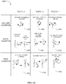
- FIG. 2B is an example diagram 201 illustrating example sensor outputs 205-209 of the example membrane sensors 200 (e.g., the first membrane sensor 214, the second membrane sensor 216, the third membrane sensor 218) of FIG. 2 .
- the first membrane sensor 214 provides first ones of the first sensor outputs (e.g., the limb sensor outputs 120). Specifically, during movement of the shoulder 208, the first membrane sensor 214 generates a first sensor output 205. Based on a position of the elbow 206 (e.g., bent or straight), the second membrane sensor 216 generates a second sensor output 207.
- the third membrane sensor 218 of the illustrated example Based on a position of the hand (e.g., bent or straight at the wrist) and/or a position of a forearm (e.g., twist position or rotational position relative to a longitudinal axis along the forearm), the third membrane sensor 218 of the illustrated example generates a third sensor outputs 209.
- a position of the hand e.g., bent or straight at the wrist
- a position of a forearm e.g., twist position or rotational position relative to a longitudinal axis along the forearm
- Each example of the sensor outputs 205-209 is representative of movements of the arm 102a relative to an initial position (e.g., the arm 102a positioned against the side of the body 106 with palm against the body 106).
- the example sensor outputs 205-209 are representative of, and/or can be used to, detect an amount of strain imparted to the arm 102a during movement as the shoulder 208 rotates relative to the body 106, the elbow 206 bends at the elbow joint, the hand bends at the wrist 202, the arm 102a rotates relative to the shoulder 208, the forearm twists relative to the elbow and/or the shoulder, and/or any other position of the arm 102a relative to the body 106.
- the other positions can include various positions (e.g., rotating the arm 102a outward, lifting the arm 102a above a user's head, rotating the arm 102a in a circle, etc.).
- the outputs 205-209 can be a voltage signal, a current signal and/or any other type of signal.
- FIG. 3A-3E illustrate an example membrane sensor 300 that can implement membrane sensors 200 of the example ergonomics improvement system 100 of FIGS. 1 and 2 .
- the membrane sensor 300 of the illustrated example includes a membrane 302 (e.g., a membrane layer) and a sensor 304 (e.g., a sensor layer).
- FIG. 3A is a side view of the example membrane sensor 300.
- FIG. 3B is a top view of the example membrane 302 and
- FIG. 3C is an enlarged portion of the example membrane 302 of FIG. 3B.
- FIG. 3D is a top view of the example sensor 304 and FIG. 3E is an enlarged portion of the example sensor 304 of FIG. 3D .
- the membrane sensor 300 of the illustrated example can implement the first membrane sensor 214, the second membrane sensor 216 and/or the third membrane sensor 218 of FIG. 2 .
- the membrane sensor 300 of FIGS. 3A-3E can be formed or shaped to similar to the first membrane sensor 214, the second membrane sensor 216, the third membrane sensor 218, and/or can have any other shape (e.g., a waist band, a belt, etc.) to fit on and/or around a portion of the body 106.
- the membrane sensor 300 of the illustrated example is flexible and can conform (e.g., bend, wrap, etc.) to portions (e.g., the shoulder 208, the elbow 206, the wrist 202 of FIG. 2 ) of the body 106.
- the membrane 302 of the illustrated example couples to the sensor 304 via adhesive 306 (e.g., an adhesive layer 306).
- the adhesive 306 is positioned between the membrane 302 and the sensor 304.
- the adhesive 306 can include, but is not limited to, a plastic, a tape, glue, a paste, and/or any other type of adhesive.
- the membrane 302 of the illustrated is a hexagonal meta-membrane.
- the membrane 302 of FIG. 3B includes a first frame 308.
- the first frame 308 includes a plurality of first openings or cutouts 310.
- the frame 308 includes a plurality of flexible legs 312 (e.g., strips, frame portions, etc.) that are formed by the first cutouts 310.
- the first frame 308 (e.g., via the first legs 312 and/or the first cutouts 310) defines a first pattern 314 (e.g., an auxetic hexagonal pattern).
- the first pattern 314 is an Auxetic or hexagonal pattern.
- the membrane 302 can be rubber, plastic, aluminum, copper, and/or any other material(s) that can flex or conform to a part of the body 106.
- the sensor 304 is an electrical sensor (e.g., a strain sensor) that generates electrical outputs based on a flexed position of the sensor 304.
- the sensor 304 of FIGS. 3A-3E can be a strain sensor, piezoelectric sensor, a flex circuit and/or any other flexible sensor that provides and/or generates output signals (e.g., the limb sensor outputs 120) when flexed, bent, and/or otherwise moved relative to an initial position.
- the electrical signals output by the sensor 304 can be communicated to the controller 108 via the wires 203 ( FIG. 2 ).
- the sensor 304 of the illustrated example includes a second frame 318.
- the second frame 318 includes a plurality of second openings or cutouts 320.
- the second frame 318 includes a plurality of flexible second legs 322 (e.g., strips, frame portions, etc.) that are formed by the second cutouts 320.
- the second frame 318 (e.g., via the second legs 322 and/or the second cutouts 320) defines a second pattern 324 (e.g., auxetic hexagonal pattern).
- the second pattern 324 is an Auxetic.
- the first pattern 314 of the membrane 302 is complementary (e.g., identical) to the second pattern 324.
- FIGS. 3C and 3E are enlarged views of the membrane 302 of FIG. 3B and the sensor 304 of FIG. 3D , respectively.
- each of the first pattern 314 and the second pattern 324 includes substantially similar (e.g., identical) dimensional characteristics.
- substantially similar identical dimensional characteristics means that dimensions of the membrane 302 and the sensor 304 are identical or within a certain manufacturing tolerance (e.g., between approximately 0.5 percent and 10 percent).
- the first pattern 314 and the second pattern 324 include a plurality of interconnected triangular-shaped portions or sections 326 that each include a dimensional length La, a dimensional height Ha, an angle ⁇ , a thickness Wa, and radii r as shown in FIGS. 3C and 3E .
- the dimensional height H a is a length of a base 328a of a triangular section 326a.
- the angle ⁇ symbol is an of respective side legs 328b, 328c of the triangular section 326a relative to horizontal.
- the dimension L a is a distance between a tip 328d of the triangular section 326a and the base 328a of the triangular section 326a.
- the tip 328d is defined by respective ends of the legs 328b, 328c opposite the base 328a.
- the respective ends of the legs 328b, 328c proximate the tip 328d are not connected (e.g., are disconnected) to form a gap 329 therebetween.
- the radius r is a radius of corners of the triangular-shaped sections 326.
- the dimension W a is a width of the legs 312, 322 of the respective first and second patterns 314, 324.
- the dashed lines in FIGS. 3C and 3E are part of dimension lines and form no part of the first pattern 314 and the second pattern 324.
- the first cutouts 310 extend (e.g., completely) through a meta-membrane thickness 330 ( FIG.
- the first cutouts 310 and/or the second cutouts 320 can be formed as recessed cavities that do not extend (e.g., completely) through (or partially extend through a portion) the respective meta-membrane thickness 330 and sensor device thickness 332 of the membrane 302 and/or the sensor 304.
- Table 1 below provides example dimensional values that can be used to implement the first pattern 314 and/or the second pattern 316. The example dimensions are provided as an example and the membrane sensor 300 is not limited to the parameters, values, and units shown. In other examples, the membrane sensor 300 can be formed with any other dimensional values. Table 1: PARAMETER VALUE UNIT W a 0.25 millimeter L a 2.25 millimeter H a 2.5 millimeter r 0.5 millimeter ⁇ 29 Degree
- FIGS. 4A-4E illustrate another example membrane sensor 400 disclosed herein that can implement the example ergonomics improvement system 100 of FIGS. 1 and 2 .
- the membrane sensor 400 of the illustrated example includes a membrane 402 (e.g., a membrane layer) and a sensor 404 (e.g., a sensor layer).
- FIG. 4A is a side view of the example membrane sensor 400.
- FIG. 4B is a top view of the example membrane 402 and
- FIG. 4C is an enlarged portion of the example membrane 402 of FIG. 4B.
- FIG. 4D is a top view of the example sensor 404 and FIG. 4E is an enlarged portion of the example sensor 404 of FIG. 4D .
- the membrane sensor 400 of the illustrated example can implement the first membrane sensor 214, the second membrane sensor 216 and/or the third membrane sensor 218 of FIG. 2 .
- the membrane sensor 400 of FIGS. 4A-4E can be formed or shaped similar to the first membrane sensor 214, the second membrane sensor 216, the third membrane sensor 218, and/or can have any other shape (e.g., a waist band, a belt, etc.) to fit on and/or around a portion of the body 106.
- the membrane sensor 400 of the illustrated example is flexible and can conform (e.g., bend, wrap, etc.) to portions (e.g., the shoulder 208, the elbow 206, the wrist 202 of FIG. 2 ) of the body 106.
- the membrane 402 of the illustrated example couples to the sensor 404 via adhesive 406 (e.g., an adhesive layer).
- the adhesive 406 can include a plastic, tape, glue, latex strip, and/or any other type of adhesive.
- the adhesive 406 is positioned between the membrane 402 and the sensor 404.
- the membrane 402 of the illustrated example includes a first frame 408.
- the first frame 408 of FIG. 4A and 4E includes a plurality of first openings or cutouts 410 defining a first pattern 412 to improve or increase flexibility and/or stretchability characteristics of the membrane sensor 400.
- the first pattern 412 of the illustrated example is a Kirigami pattern (e.g., a bi-axial Kirigami pattern).
- the membrane 402 can be rubber, plastic, aluminum, copper, and/or any other material(s) that can flex or conform to a part of the body 106.
- the sensor 404 is an electrical sensor (e.g., a strain sensor) that generates electrical outputs based on a flexed position of the sensor 404.
- the sensor 404 of FIGS. 4A-4E can be a strain sensor, piezoelectric sensor, a flex circuit and/or any other flexible sensor that provides and/or generates output signals (e.g., the limb sensor outputs 120) when flexed, bent, and/or otherwise moved relative to an initial position.
- the electrical signals output by the sensor 404 can be communicated to the controller 108 via the wires 203 ( FIG. 2 ).
- the sensor 404 includes a second frame 418 having a plurality of second openings or cutouts 420 defining a second pattern 422.
- the second pattern 422 of the illustrated example is a Kirigami pattern.
- the first pattern 412 is complementary (e.g., identical) to the second pattern 422.
- FIGS. 4C and 4E are enlarged views of the membrane 402 of FIG. 4B and the sensor 404 of FIG. 4D , respectively.
- each of the first pattern 412 and the second pattern 422 includes substantially similar (e.g., identical) dimensional characteristics.
- substantially similar identical dimensional characteristics means that dimensions of the membrane 402 and the sensor 404 are identical or within a certain manufacturing tolerance (e.g., between approximately 0.5 percent and 10 percent).
- the first cutouts 410 of the first pattern 412 have a first set 410a of the first cutouts 410 positioned in a first orientation and a second set 410b of the first cutouts 410 positioned in a second orientation different than the first orientation.
- the first set 410a of the first cutouts 410 is substantially perpendicular to the second set 410b of the first cutouts 410.
- the second cutouts 420 of the second pattern 422 have a first set 420a of the second cutouts 420 positioned in a first orientation and a second set 420b of the second cutouts 420 positioned in a second orientation different than the first orientation.
- the first set 420a of the second cutouts 420 is substantially perpendicular (e.g., perfectly orthogonal or almost perfectly orthogonal (e.g., within 10 degrees of perpendicularity)) to the second set 420b of the second cutouts 420.
- the first cutouts 410 and the second cutouts 420 each include a length H b and a width W b . Additionally, a distance Wc separates respective ones of the first set 410a of the first cutouts 410a and respective ones of the second set 410b of the first cutouts 410. Likewise, a distance Wc separates respective ones of the first set 420a of the second cutouts 420, and respective ones of the second set 420b of the second cutouts 420.
- a length L a is a distance between respective ones of the first set 410a of the first cutouts 410, and respective ones of the first set 420a of the second cutouts 420.
- the length L b is a distance between respective ones of the second set 410b of the first cutouts 410 and respective ones of the second set 420b of the second cutouts 420.
- the width W b and the distance Wc are equivalent.
- the length L a and length L b are equivalent.
- the width W b and the distance Wc and/or the length L a and length L b can be different values.
- first set 410a of the first cutouts 410 can be oriented at an angle relative to the second set 410b of the first cutouts 410 and/or the first set 420a of the second cutouts 420 can be oriented at an angle relative to the second set 420b of the second cutouts 420.
- first cutouts 410 and/or the second cutouts 420 can have any other suitable pattern.
- the first cutouts 410 extend (e.g., completely) through a meta-membrane thickness 430 ( FIG. 4A ) of the membrane 402 and the second cutouts 420 extend (e.g., completely) through a sensor device thickness 432 ( FIG. 4A ) of the sensor 404.
- the first cutouts 410 and/or the second cutouts 420 can be formed as recessed cavities (e.g., slots, slits, channels, etc.) that do not extend (e.g., completely) through (or partially extend through a portion) the respective meta membrane thickness 430 and sensor device thickness 432 of the membrane 402 and/or the sensor 404.
- Table 2 below provides example dimensional values that can be used to implement the first pattern 412 and/or the second pattern 422. The example dimensions are provided as an example and the membrane sensor 400 is not limited to the parameters, values, and units shown. In other examples, the membrane sensor 400 can be formed with any other dimensional values.
- Table 2 PARAMETER VALUE UNIT W b 0.25 millimeter W C 0.25 millimeter L a 1.75 millimeter L b 1.75 millimeter H b 3.25 millimeter
- FIG. 5 is a schematic illustration of example displacement and stress distribution of a membrane sensor 500, the example membrane sensor of FIGS. 3A-3E and the example membrane sensor of FIGS. 4A-4E .
- the membrane sensor 500 includes a membrane 502 that is formed without cutouts or openings.
- FIG. 5 illustrates side views of the membranes sensor 500, the membrane sensor 400 and the membrane sensor 300 labeled as (a), (c), and (e), respectively.
- FIG. 5 also illustrates top views of the membranes sensors 500, 400, 300 labeled as (b), (d), and (f), respectively.
- the membrane sensor 500, the membrane sensor 400 and the membrane sensor 300 are shown in respective flexed or stretched positions when a similar or identical force (or a flex position of the arm 102a) is imparted to the respective membrane sensors 500, 400, 300.
- FIG. 5 illustrates differences in flexibility between membrane sensors 500, 400, and 300.
- the membrane sensor 400 can flex greater than the membrane sensor 300 by a height 506 (e.g., approximately between 10% and 20% greater flexibility).
- the membrane sensor 500 can flex greater than the membrane sensor 400 by a height 508 (e.g., between approximately 10% and 40% greater flexibility than the membrane sensor 400 and/or between approximately 30% and 755 greater flexibility than the membrane sensor 500).
- Stress-strain mapping is shown in the membrane sensors 500, 400 and 300 when the membrane sensors 500, 400, 300 are flexed to the positions shown in FIG. 5 .
- a strain key 510 to indicate levels of strain. Although the membrane sensor 500 stretches or flexes the least amount, the membrane sensor 500 experiences a greater amount of strain and/or stress compared to the membrane sensors 400 and 500.
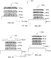
- FIGS. 6A-6D illustrate other example membrane sensors 600a-d disclosed herein that can be used to implement the ergonomics improvement system of FIGS. 1 and 2 .
- the membrane sensors 600a-d e.g., strain sensors, flex circuit
- the membrane sensors 600a-d can be assembled in various configurations including, for example, including a first membrane sensor 600a, a second membrane sensor 600b, a third membrane sensor 600c, and a fourth membrane sensor 600d.
- the membrane sensors 600a-600d can implement the example membrane sensors 200 of FIG. 2 , the membrane sensors 300 of FIGS. 3A-3E , and/or the membrane sensors 400 of FIG. 4A-4E .
- the first membrane sensor 600a includes a membrane 604 (e.g., a wearable membrane), a sensor 608 (e.g., strain sensing element), and a first adhesive 606 (e.g., an adhesive layer) that can couple or attach (e.g., directly) to skin 602 of the user 106a.
- the membrane 604 attaches to the skin 602 of the user 106a.
- the first adhesive 606 is positioned between the membrane 604 and the sensor 608 and couples or attaches the membrane 604 and the sensor 608.
- the membrane 604 When coupled to the body 106, the membrane 604 is between a first side of the first adhesive 606 and the skin 602 of the user 106a (e.g., above the skin 602), and the sensor 608 is positioned adjacent or proximate (e.g., directly engaged with) a second side of the first adhesive 606 opposite the first side.
- the second membrane sensor 600b includes the sensor 608, the first adhesive 606, the membrane 604, and a second adhesive 612.
- the second adhesive 612 can be used to couple (e.g., directly couple) the membrane 604 to the skin 602 of the user 106a.
- the membrane 604 is positioned between the first adhesive 606 and the second adhesive 612, and the second adhesive 612 is positioned between the membrane 604 and the skin 602 when coupled to the body 106.
- the first adhesive is positioned between and couples the membrane 604 and the sensor 608.
- the third membrane sensor 600c includes the membrane 604 positioned between the sensor 608 and the first adhesive 606.
- the sensor 608 attaches to and/or is integrally formed with the membrane 604.
- the first adhesive 606 couples or attaches the membrane 604 and the sensor 608 to clothing 610 to be worn by the user 106a.
- the clothing 610 retains or maintains the membrane sensor 600a on the user 106a.
- the sensor 608 is positioned proximate (e.g., directly engaged with) the skin 602 of the user 106a when the clothing 610 having the membrane sensor 600c is worn by the user 106a. In other words, the sensor 608 is inside or located on an interior side of the clothing 610 when the clothing 610 is worn by the user 106a.
- the fourth membrane sensor 600d includes the sensor 608, the first adhesive 606, the membrane 604, the second adhesive 612 and the clothing 610.
- the first adhesive 606 couples or attaches the membrane 604 and the sensor 608.
- the first adhesive is positioned between the sensor 608 and the membrane 604.
- the second adhesive 612 attaches the membrane 604 and the clothing 610.
- the second adhesive is positioned between the membrane 604 and the clothing 610.
- the clothing 610 is positioned proximate the skin 602 of the user 106a.
- the sensor 608 is exposed or located on an exterior side of the clothing 610 when the clothing 610 is worn by the user 106a.
- the sensors 608 can be various types of sensors (e.g., strain sensors).
- sensors 608 of FIGS. 6A-6D FIGS. 6 e.g., and the sensors 304 of FIGS.
- 3A-3E and/or the sensors 404 of FIGS.4A-4E can include, but are not limited to, a load cell sensor, piezoelectric devices or sensors, flexible circuit boards, conductive materials including carbon nanomaterials (e.g., carbon blacks [CBs], carbon nanotubes [CNTs], graphene and its derivatives), metal nanowires (NWs), nanofibers (NFs), and nanoparticles (NPs), MXenes (e.g., Ti3C2Tx), ionic liquid, hybrid micro-/nanostructures, conductive polymers, and/or any other strain and/or stress sensing material(s) or sensor(s) that can generate output signals (e.g., electrical signals, the limb sensor outputs 120) when flexed, bent, and/or otherwise distorted.
- output signals e.g., electrical signals, the limb sensor outputs 120
- the membrane 604 (e.g., and the membrane 302 of FIGS. 3A-3E and/or the membrane 402 of FIGS.4A-4E ) can be formed of various types of materials including, but not limited to, silicone elastomers (e.g., ecfoex and polydimethylsilowane [PDMS]), rubbers, thermoplastic polymers, medical adhesive films, thermoplastic polyurethane (TPU), polystyrene-based elastomers, PDMS, natural fiber-based materials such as cotton, wool, flax, and/or any other material(s) having flexible characteristics.
- silicone elastomers e.g., ecfoex and polydimethylsilowane [PDMS]
- rubbers e.g., ecfoex and polydimethylsilowane [PDMS]
- thermoplastic polymers e.g., ecfoex and polydimethylsilowane [PDMS]
- the membrane sensor 200, 300, 400, and 600a-600d can have various thicknesses in a z-direction (e.g., stack-up direction/cross-section).
- a thickness of the membrane 302, 402 and/or 604 can be the same or different than as a thickness of the sensor 304, 404 and/or 606.
- the membrane sensor 200, 300, 400 and/or 600a-d, the membrane 302, 402, 604, and/or the sensor 304, 404, 608 can be formed via molding (e.g., injection molding), additive manufacturing (e.g., 3D-printing), lithography, a combination thereof, and/or any other manufacturing process(es).
- FIG. 7A is an example lower body sensor system 700 disclosed herein that can be used to implement the example ergonomics improvement system 100 of FIG. 1 .
- the lower body sensor system 700 of the illustrated example implements the load sensor 112 and the position sensor 114 of FIG. 1 .
- the load sensor 112 includes load cells 706 and the position sensor 114 includes Light Detection and Ranging (LiDAR) sensors 704 (e.g., a pressure pad, step scan sensor, etc.).
- the load cells 706 and the LiDAR sensors 704 are incorporated (e.g., carried by, attached, or otherwise embedded) in a pair of shoes 702 to be worn by the user 106a.
- the LiDAR sensors 704 emits pulsed waves into a surrounding environment.
- the pulses bounce off the opposing shoe and return to the sensor.
- the sensor uses a time differential for each pulse to return to the sensor to calculate a distance traveled.
- the pulsed waves project into the surrounding environment instead of an otherwise opposing shoe, indicating that the user's feet are spread apart.
- pulses emitted by the LiDAR sensors 704 can be used to determine if the user 106a is standing in a stable or bracing position (e.g., with one foot spaced apart and in front of their other foot) or a non-stable or non-bracing position (e.g., a user standing with their feet spaced apart, but the left foot substantially in line with the right foot) when performing the physical tasks.
- a stable or bracing position e.g., with one foot spaced apart and in front of their other foot
- a non-stable or non-bracing position e.g., a user standing with their feet spaced apart, but the left foot substantially in line with the right foot
- FIG. 7B is another example lower body sensor system 700 of the example ergonomics improvement system 100 of FIG. 1 .
- the lower body sensor system 700 of the illustrated example implements the load sensor 112 and the position sensor 114 of FIG. 1 .
- the load sensor 112 includes load cells 706 and the position sensor 114 includes pressure sensors 708 (e.g., a pressure pad, step scan sensor, etc.).
- the load cells 706 and the pressure sensors 708 are located in (e.g., embedded in the soles of) a pair of shoes 702 that can be worn by the user 106a ( FIG. 1 ).
- the load cells 706 measure a load or weight of the user 106a to determine an amount of weight that the user 106a is holding or lifting.
- the pressure sensors 708 of the illustrated example can detect and/or determine a stance (e.g., feet positioning) of the user 106a performing a physical task.
- the pressure sensors 708 can detect and/or otherwise determine if a user is standing in a stable or bracing position (e.g., with one weight evenly distributed in the feet) or a non-stable or non-bracing position (e.g., a user standing with their weight all centered forward on the toes or all centered backwards on the heels) when performing a physical task.
- the pressure sensors 708 can be used to determine weight distribution of the user (e.g., whether the weight distribution is centered).
- a weight of the user 106a being offset toward the heels of the user 106a can indicate that the user 106a is off-balance and/or at risk of falling or being injured.
- the ergonomics improvement system 100 can determine if the user's stance is stable (e.g., or optimal) for carrying a detected load (e.g., the object 119 of FIG. 1 ).
- FIGS. 8A and 8B are schematic illustrations of example third outputs 800 of the example lower body sensor system 700 of FIG. 7A .
- FIG. 8A illustrates a first one 801 of the third outputs 800
- FIG. 8B illustrates a second one 803 of the third outputs 800.
- the first one 801 of the third outputs 800 is representative of the user 106a having his/her feet spaced apart, but a left foot 805 substantially even with a right foot 807.
- the second one 803 of the third outputs 800 of FIG. 8B is representative of the user 106a having the right foot 807 spaced apart and in front of the left foot 805.
- the pressure sensors 708 generate Stepscan or pressure outputs, such as shown in FIG. 8A and 8B .
- the third outputs 800 of the pressure sensors 708 can detect pressure distribution across the feet of the user 106a.
- a white colored area 802 in FIGS. 8A and 8B indicates an area with low pressure
- a grey colored area 804 in FIGS. 8A and 8B indicates medium pressure
- a black colored area 806 in FIGS. 8A and 8B indicates high pressure.
- FIG. 8A the user has more pressure on his/her right foot 807 as indicated by more grey colored area 804 and more black colored area 806 as compared to the left foot 805, which has more white colored area 802.
- FIG. 8B illustrates the weight of the user 106a concentrated in the back heel of the right foot 807 and concentrated on a pad or middle area of the left foot 805.
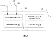
- FIG. 9 is a block diagram of the example controller 108 of the example ergonomics improvement system 100 of FIG. 1 .
- the controller 108 includes a sensor manager 902, a data monitor 904, a warning device manager 906, and a calibrator 908.
- the sensor manager 902, the data monitor 904, the warning device manager 906 and the calibrator 908 are communicatively coupled via a bus 910.
- the sensor manager 902 receives inputs from the limb sensor 110, the load sensor 112, or/and the position sensor 114.
- the sensor manager 902 receives the limb sensor outputs 120, the load sensor outputs 122, and/or the position sensor outputs 124.
- the sensor manager 902 receives the outputs 205-209, the outputs from the load cells 706, and the outputs from the pressure sensors 708 and/or the LiDAR sensors 704.
- the sensor manager 902 receives the outputs as currents, voltages, etc.
- the sensor manager 902 can condition the signals for processing by the data monitor 904.
- the sensor manager 902 converts the inputs to binary values (e.g., on/off), digital values, and/or an analog values.
- the sensor manager 902 can convert the signals of the position sensor 114 to binary values.
- the sensor manager 902 can provide binary values "1" for respective ones of the outputs 205-209 of the in response to the output signals not exceeding a threshold value (e.g., an electric current) associated with the respective ones of the membrane sensors 214, 216, 218 and can provide binary values "0" for respective ones of the outputs 205-209 of the membrane sensors 214, 216, 218 in response to the output signals exceeding a threshold value (e.g. an electric current) associated with the respective ones of the membrane sensors 214, 216, 218.
- a threshold value e.g., an electric current
- the sensor manager 902 can provide a binary value "1" when the position sensor 114 provides signals representative of the user 106a being in the stable stance and a binary value "0" when the position sensor 114 provides signals representative of the user 106a being in a non-stable stance.
- the sensor manager 902 can provide a binary value "1” in response to the load sensor 112 providing a signal representative of a weight that is greater than a threshold (e.g., 50 pounds) and a binary value "0" in response to the load sensor 112 providing a signal representative of a weight being less than the threshold.
- a threshold e.g. 50 pounds
- the data monitor 904 stores and processes the signal(s) from the sensor manager 902.
- the data monitor 904 can compare signal(s) from the sensor manager 902 to a threshold.
- the threshold can be obtained, retrieved or otherwise accessed from memory by the data monitor 904.
- the data monitor 904 via a comparator, can compare the signals from the sensor manager 902 to a table to determine if the user 106a is performing a non-ergonomic or improper activity based on the data provided by the limb sensor outputs 120, the load sensor outputs 122, and/or the position sensor outputs 124.
- data monitor 904 can compare the signals from the sensor manager 902 to threshold values stored in a look-up table associated with respective thresholds for the respective ones of the limb sensor outputs 120, the load sensor outputs 122 and/or the position sensor output 124. For example, the data monitor 904 can compare a determined position of the limb 102 to a position threshold associated with a measured load carried by the user 106a provided by the load sensor 112 and a determined position of the right foot 807 relative to the left foot 805.
- the data monitor 904 can communicate a warning activation signal to the warning device manager 906 in response to determining that the detected position of the limb 102 exceeds a position threshold (e.g., from a look-up table) associated with or corresponding to the measured load from the load sensor 112 and/or the detected position of the right foot 807 relative to the left foot 805.
- a position threshold e.g., from a look-up table
- the outputs 205-209 of FIG. 13 can be indicative of non-ergonomic or improper movement or position of the limb 102 if a load carried by the user 106a exceeds a threshold load and/or a stance of the user 106a is a non-stable stance (e.g., a stance shown in FIG. 8A ).
- the outputs 205-209 of FIG. 13 can be indicative of ergonomic or proper movement or position of a limb 102 if a load carried by the user 106a does not exceed a threshold load and/or a stance of the user 106a is a stable stance (e.g., a stance shown in FIG. 8B ).
- the look-up table can have a plurality of first threshold values corresponding to outputs from the membrane sensors 214, 216, 218. Based on a comparison of the outputs from the membrane sensors 214, 216, 218 and the thresholds corresponding to the respective ones of the membrane sensors 214, 216, 218 stored in the lookup table, the weight provided by the load sensor 112, and the feet stance provided by the position sensor 114, the data monitor 904 determines if the user 106a is conducting activity (e.g., based on limb movement or position) that is ergonomically proper or ergonomically improper.
- conducting activity e.g., based on limb movement or position
- the warning device manager 906 triggers the warning signal 126 to trigger an alarm (e.g., indicative of a non-ergonomic activity or movement).
- the warning device manager 906 can receive a signal from the data monitor 904 if the signal from the sensor manager 902 exceeds a threshold.
- the warning device manager 906 can send the warning signal 126 and/or alarm.
- Example alarms disclosed herein include, but are not limited to, visual alarms (e.g., a light), audio alarms (e.g., a speaker), haptic feedback, a combination thereof and/or any other alarm(s).
- the calibrator 908 instructs users of motions to complete calibration such as those illustrated in FIG. 12 .
- the calibrator 908 also stores movement data from various positions from the calibration and can process the movement data to be used as thresholds for the data monitor 904.
- the calibrator 908 sets a zero or reference value for the limb sensor 110, the load sensor 112 and the position sensor 114.
- the controller 108 of the illustrated example can be configured to communicate the sensor outputs (e.g., the sensor outputs 120, 122, 124, 205-209, 800 etc.) from the upper body sensor system 111a and/or the lower body sensor system 111b to a remote electronic device such as, for example, a server, a computer, a control room, a mobile device, a mobile phone, and/or any other computing device communicatively coupled to the controller 108 of the ergonomics improvement system 100.
- a remote electronic device such as, for example, a server, a computer, a control room, a mobile device, a mobile phone, and/or any other computing device communicatively coupled to the controller 108 of the ergonomics improvement system 100.
- the controller 108 and/or the sensor manager 902 can transmit or communicate one or more outputs provided by the sensors (e.g., the limb sensor 110, the load sensor 112, the position sensor 114, the membrane sensors 214, 216, 218, the load cells 706, the pressure sensors 708, the LiDAR sensors 704 and/or any other sensor(s)).
- the remote electronic device can be configured to model the movement of the user 106a (e.g., the arm 102a of the user 106a) based on the data provided by the controller 108.
- the remote electronic device can be configured to detect whether the model represents movements that can be indicative of movements that can be ergonomic or acceptable, or movements that can be non-ergonomic or not acceptable..
- the remote electronic device determines that the movements of the user 106a are acceptable, the remote electronic device does not communicate with the controller 108. If the remote electronic device determines that the movements of the user 106a are not acceptable, the remote electronic device communicate instructions to the controller 108 to cause the warning device manager 906 to initiate the warning signal 126 to active the warning device 116.
- FIG. 9 While an example manner of implementing the controller 108 of FIG. 1 is illustrated in FIG. 9 , one or more of the elements, processes and/or devices illustrated in FIG. 9 may be combined, divided, re-arranged, omitted, eliminated and/or implemented in any other way.
- the sensor manager 902, the data monitor 904, the warning device manager 906, and the calibrator 908.and/or, more generally, the example controller of FIG. 1 may be implemented by hardware, software, firmware and/or any combination of hardware, software and/or firmware.
- FIG. 1 could be implemented by one or more analog or digital circuit(s), logic circuits, programmable processor(s), programmable controller(s), graphics processing unit(s) (GPU(s)), digital signal processor(s) (DSP(s)), application specific integrated circuit(s) (ASIC(s)), programmable logic device(s) (PLD(s)) and/or field programmable logic device(s) (FPLD(s)).
- GPU graphics processing unit
- DSP digital signal processor
- ASIC application specific integrated circuit
- PLD programmable logic device
- FPLD field programmable logic device
- FIG. 1 is/are hereby expressly defined to include a non-transitory computer readable storage device or storage disk such as a memory, a digital versatile disk (DVD), a compact disk (CD), a Blu-ray disk, etc. including the software and/or firmware.
- the example controller 108 of FIG. 1 may include one or more elements, processes and/or devices in addition to, or instead of, those illustrated in FIG. 9 , and/or may include more than one of any or all of the illustrated elements, processes and devices.
- the phrase "in communication,” including variations thereof, encompasses direct communication and/or indirect communication through one or more intermediary components, and does not require direct physical (e.g., wired) communication and/or constant communication, but rather additionally includes selective communication at periodic intervals, scheduled intervals, aperiodic intervals, and/or one-time events.
- FIG. 10 and FIG. 11 A flowchart representative of example hardware logic, machine readable instructions, hardware implemented state machines, and/or any combination thereof for implementing the ergonomics improvement system 100 of FIG. 1 is shown in FIG. 10 and FIG. 11 .
- the machine readable instructions may be one or more executable programs or portion(s) of an executable program for execution by a computer processor such as the processor 1312 shown in the example processor platform 1300 discussed below in connection with FIG. 1 .
- the program may be embodied in software stored on a non-transitory computer readable storage medium such as a CD-ROM, a floppy disk, a hard drive, a DVD, a Blu-ray disk, or a memory associated with the processor 1312, but the entire program and/or parts thereof could alternatively be executed by a device other than the processor 1312 and/or embodied in firmware or dedicated hardware.
- a non-transitory computer readable storage medium such as a CD-ROM, a floppy disk, a hard drive, a DVD, a Blu-ray disk, or a memory associated with the processor 1312
- the entire program and/or parts thereof could alternatively be executed by a device other than the processor 1312 and/or embodied in firmware or dedicated hardware.
- the example program is described with reference to the flowcharts illustrated in FIG. 10 and FIG. 11 , many other methods of implementing the example ergonomics improvement system 100 may alternatively be used. For example, the order of execution of the blocks may be changed, and/
- any or all of the blocks may be implemented by one or more hardware circuits (e.g., discrete and/or integrated analog and/or digital circuitry, an FPGA, an ASIC, a comparator, an operational-amplifier (op-amp), a logic circuit, etc.) structured to perform the corresponding operation without executing software or firmware.
- hardware circuits e.g., discrete and/or integrated analog and/or digital circuitry, an FPGA, an ASIC, a comparator, an operational-amplifier (op-amp), a logic circuit, etc.
- the machine readable instructions described herein may be stored in one or more of a compressed format, an encrypted format, a fragmented format, a compiled format, an executable format, a packaged format, etc.
- Machine readable instructions as described herein may be stored as data (e.g., portions of instructions, code, representations of code, etc.) that may be utilized to create, manufacture, and/or produce machine executable instructions.
- the machine readable instructions may be fragmented and stored on one or more storage devices and/or computing devices (e.g., servers).
- the machine readable instructions may require one or more of installation, modification, adaptation, updating, combining, supplementing, configuring, decryption, decompression, unpacking, distribution, reassignment, compilation, etc.
- the machine readable instructions may be stored in multiple parts, which are individually compressed, encrypted, and stored on separate computing devices, wherein the parts when decrypted, decompressed, and combined form a set of executable instructions that implement a program such as that described herein.
- the machine readable instructions may be stored in a state in which they may be read by a computer, but require addition of a library (e.g., a dynamic link library (DLL)), a software development kit (SDK), an application programming interface (API), etc. in order to execute the instructions on a particular computing device or other device.
- a library e.g., a dynamic link library (DLL)
- SDK software development kit
- API application programming interface
- the machine readable instructions may need to be configured (e.g., settings stored, data input, network addresses recorded, etc.) before the machine readable instructions and/or the corresponding program(s) can be executed in whole or in part.
- the disclosed machine readable instructions and/or corresponding program(s) are intended to encompass such machine readable instructions and/or program(s) regardless of the particular format or state of the machine readable instructions and/or program(s) when stored or otherwise at rest or in transit.
- the machine readable instructions described herein can be represented by any past, present, or future instruction language, scripting language, programming language, etc.
- the machine readable instructions may be represented using any of the following languages: C, C++, Java, C#, Perl, Python, JavaScript, HyperText Markup Language (HTML), Structured Query Language (SQL), Swift, etc.
- FIG. 10 and FIG. 11 may be implemented using executable instructions (e.g., computer and/or machine readable instructions) stored on a non-transitory computer and/or machine readable medium such as a hard disk drive, a flash memory, a read-only memory, a compact disk, a digital versatile disk, a cache, a random-access memory and/or any other storage device or storage disk in which information is stored for any duration (e.g., for extended time periods, permanently, for brief instances, for temporarily buffering, and/or for caching of the information).
- a non-transitory computer readable medium is expressly defined to include any type of computer readable storage device and/or storage disk and to exclude propagating signals and to exclude transmission media.
- A, B, and/or C refers to any combination or subset of A, B, C such as (1) A alone, (2) B alone, (3) C alone, (4) A with B, (5) A with C, (6) B with C, and (7) A with B and with C.
- the phrase "at least one of A and B" is intended to refer to implementations including any of (1) at least one A, (2) at least one B, and (3) at least one A and at least one B.
- the phrase "at least one of A or B" is intended to refer to implementations including any of (1) at least one A, (2) at least one B, and (3) at least one A and at least one B.
- the phrase "at least one of A and B" is intended to refer to implementations including any of (1) at least one A, (2) at least one B, and (3) at least one A and at least one B.
- the phrase "at least one of A or B" is intended to refer to implementations including any of (1) at least one A, (2) at least one B, and (3) at least one A and at least one B.
- the method 1000 of FIG. 10 is an example method for implementing the ergonomics improvement system 100 of FIG. 1 .
- the method 1000 begins at block 1002, with the sensor manager 902 receiving data collected from sensor(s).
- the sensor(s) can include the limb sensor 110, the load sensor 112, the position sensor 114, the membrane sensors 214, 216, 218, the load cells 706, the pressure sensor 708, the LiDAR sensors 704 and/or any other sensor(s).
- the data monitor 904 compares data (e.g., signals(s)) from the sensor manager 902 data to a threshold.
- the threshold can be obtained from a lookup table that can be stored in a database or memory of the controller 108.
- the data monitor 904 determines whether the threshold at block 1004 is exceeded. If the data monitor 904 determines that the threshold is exceeded at block 1006, then the process continues to block 1008. At block 1008, the warning device manager 906 initiates a warning signal (e.g., the warning signal 126) to activate the alarm and/or warning device 116. If the data monitor 904 determines at block 1006 that the threshold is not exceeded, then the process returns to block 1002.
- a warning signal e.g., the warning signal 126
- the method 1100 is an example method to calibrate the upper body sensor system 111a and the lower body sensor system 111b of the example ergonomics improvement system 100 of FIG. 1 .
- calibration can be implemented using the calibrator 908.
- calibration of the example ergonomics improvement system 100 of FIG. 1 can occur when the system is initially turned on and/or at any other time when the system is in use.
- calibration can be automatically set to occur at pre-defined intervals or at certain events such as when the controller 108 detects outlier values outputted by one or more sensors of the ergonomics improvement system of FIG. 1 .
- the example ergonomics improvement system 100 of FIG. 1 can detect the upper body sensor system 111a (e.g., the membrane sensors 214, 216, 218) and the lower body sensor system 111b (e.g., the load cells 706, the pressure sensor 708, the LiDAR sensor 704, etc.) via the sensor manager 902.
- the example calibrator 908 instructs the user 106a to initiate sensor calibrations.
- Example sensor calibration positions are disclosed herein and are illustrated and discussed in FIG. 12 .
- the example calibrator 908 records sensor output(s) associated with the different sensor calibrations.
- the calibrated values for each of the sensors e.g., the limb sensor 110, the load sensor 112, and/or the position sensor 114.
- FIG. 12 is an example diagram representative of example calibration positions 1200 disclosed herein that can be used to implement the example method 1100 of FIG. 11 .
- the sensor calibration positions can be instructed to the user 106a using a user interface that can include, for example, a display, a speaker, a combination thereof, and/or any other communication device carried by the controller 108.
- the example calibration positions 1200 can be used to calibrate one or more of the membrane sensors 214, 216, 218 after the sensors are carried or coupled to the user 106a. For example, each of the membrane sensors 214, 216, 218 can be calibrated using the example calibration positions 1200 of FIG. 12 .
- the calibration positions 1200 include three sets of calibration positions (i.e., position 1, position 2, position 3) for each of the shoulder 208, the elbow 206 and the hand/wrist 202.
- the calibration positions are not limited to the positions shown in FIG. 12 and can include one or more other positions that are not shown in FIG. 12 .
- a shoulder calibration 1202 the user 106a is instructed to move their arms (i.e., the arm 102a) in a forward position (e.g., a fully forward extended position in a direction in front of the user 106a) and rearward position (e.g., a fully rearward extended position in a direction behind the user 106a).
- the controller 108 records outputs of the sensors (e.g., the membrane sensors 214, 216, 218) when the arm 102a moves to the forward position and the rearward position.
- a shoulder calibration 1204 the user 106a is instructed to move their arms in an upward position (e.g., a fully raised position above the user's head) and downward position (e.g., a fully extended position on the side of the user's body).
- the controller 108 records outputs of the sensors (e.g., the membrane sensors 214, 216, 218) when the arm 102a moves to the upward position and the downward position.
- a shoulder calibration 1206 the user 106a is instructed to extend their arms outwardly and sideways (e.g., a wingspan formation) and rotate/twist their arms in a circular motion between a first rotational position (e.g., twist or rotate in a first rotational position) and a second rotational position (e.g., twist or rotate in a second rotational direction opposite the first direction).
- the controller 108 records outputs of the sensors (e.g., the membrane sensors 214, 216, 218) when the arm 102a moves to the first rotational position and the first rotational position.
- an elbow calibration 1208 the user 106a is instructed to move their arms sideways and to move their arms to a curled position (e.g., fully curled position where the hand is proximate the shoulder 208) and an extended position (e.g., a fully extended position).
- the controller 108 records outputs of the sensors (e.g., the membrane sensors 214, 216, 218) associated with the elbow 206 when the arm 102a moves to the curled position and the extended position.
- the user 106a In position 2 of an elbow calibration 1210, the user 106a is instructed to bend their elbows and move their elbows while in the bent position to a bent upward position and a bent downward position.
- the controller 108 records outputs of the sensors (e.g., the membrane sensors 214, 216, 218) when the arm 102a moves to the bent upward position and the bent downward position.
- the user 106a In position 3 of the elbow calibration 1212, the user 106a is instructed to rotate their arms with the elbow bent between a first rotational position and a second rotational position opposite the first rotational position.
- the controller 108 records outputs of the sensors (e.g., the membrane sensors 214, 216, 218) when the arm 102a, with the bent elbow 206, moves to the first rotational position and the second rotational position.
- the user 106a In position 1 of a wrist/hand calibration 1214, the user 106a is instructed to move or bend their hand about the wrist to an upward position (e.g., fully upward position) and a downward position (e.g., a fully downward position).
- the controller 108 records outputs of the sensors (e.g., the membrane sensors 214, 216, 218) when the hand moves to the first rotational position and the second rotational position.
- a wrist/hand calibration 1216 the user 106a is instructed to move their hand sideways about the wrist to a first side position (e.g., fully right side position) and a second side position (e.g., a fully left side position).
- the controller 108 records outputs of the sensors (e.g., the membrane sensors 214, 216, 218) when the hand moves to the first side position and the second side position.
- a first rotational position e.g., a fully rotational position in a first rotational direction
- a second rotational position e.g., a fully rotational position in a second rotational direction
- the controller 108 records outputs of the sensors (e.g., the membrane sensors 214, 216, 218) when the hand moves to the first rotational position and the second rotational position.
- FIG. 13 is a block diagram of an example processing platform structured to execute instructions of FIGS. 10 and 11 to implement an example controller of example ergonomics improvement systems disclosed herein.
- FIG. 13 is a block diagram of an example processor platform 1300 structured to execute the instructions of FIG. 10 and FIG. 11 to implement the ergonomics improvement system 100 of FIG. 1 .
- the processor platform 1300 can be, for example, a server, a personal computer, a workstation, a self-learning machine (e.g., a neural network), a mobile device (e.g., a cell phone, a smart phone, a tablet such as an iPad TM , a headset or other wearable device, or any other type of computing device.
- a self-learning machine e.g., a neural network
- a mobile device e.g., a cell phone, a smart phone, a tablet such as an iPad TM , a headset or other wearable device, or any other type of computing device.
- the processor platform 1300 of the illustrated example includes a processor 1312.
- the processor 1312 of the illustrated example is hardware.
- the processor 1312 can be implemented by one or more integrated circuits, logic circuits, microprocessors, GPUs, DSPs, or controllers from any desired family or manufacturer.
- the hardware processor may be a semiconductor based (e.g., silicon based) device.
- the processor implements the sensor manager 902, the data monitor 904, the warning device manager 906 and the calibrator 908.
- the processor 1312 of the illustrated example includes a local memory 1313 (e.g., a cache).
- the processor 1312 of the illustrated example is in communication with a main memory including a volatile memory 1314 and a non-volatile memory 1316 via a bus 1318.
- the volatile memory 1314 may be implemented by Synchronous Dynamic Random Access Memory (SDRAM), Dynamic Random Access Memory (DRAM), RAMBUS ® Dynamic Random Access Memory (RDRAM ® ) and/or any other type of random access memory device.
- the non-volatile memory 1316 may be implemented by flash memory and/or any other desired type of memory device. Access to the volatile memory 1314 and the non-volatile memory 1316 is controlled by a memory controller.
- the processor platform 1300 of the illustrated example also includes an interface circuit 1320.
- the interface circuit 1320 may be implemented by any type of interface standard, such as an Ethernet interface, a universal serial bus (USB), a Bluetooth ® interface, a near field communication (NFC) interface, and/or a PCI express interface.
- one or more input devices 1322 are connected to the interface circuit 1320.
- the input device(s) 1322 permit(s) a user to enter data and/or commands into the processor 1312.
- the input device(s) can be implemented by, for example, an audio sensor, a microphone, a camera (still or video), a keyboard, a button, a mouse, a touchscreen, and/or a voice recognition system.
- One or more output devices 1324 are also connected to the interface circuit 1320 of the illustrated example.
- the output devices 1324 can be implemented, for example, by display devices (e.g., a light emitting diode (LED), an organic light emitting diode (OLED), a liquid crystal display (LCD), a cathode ray tube display (CRT), an in-place switching (IPS) display, a touchscreen, etc.), and/or speaker.
- the interface circuit 1320 of the illustrated example thus, typically includes a graphics driver card, a graphics driver chip and/or a graphics driver processor.
- the interface circuit 1320 of the illustrated example also includes a communication device such as a transmitter, a receiver, a transceiver, a modem, a residential gateway, a wireless access point, and/or a network interface to facilitate exchange of data with external machines (e.g., computing devices of any kind) via a network 1326.
- the communication can be via, for example, an Ethernet connection, a digital subscriber line (DSL) connection, a telephone line connection, a coaxial cable system, a satellite system, a line-of-site wireless system, a cellular telephone system, etc.
- DSL digital subscriber line
- the processor platform 1300 of the illustrated example also includes one or more mass storage devices 1328 for storing software and/or data.
- mass storage devices 1328 include floppy disk drives, hard drive disks, compact disk drives, Blu-ray disk drives, redundant array of independent disks (RAID) systems, and digital versatile disk (DVD) drives.
- the machine executable instructions 1332 of FIG. 10 and FIG. 11 may be stored in the mass storage device 1328, in the volatile memory 1014, in the non-volatile memory 1316, and/or on a removable non-transitory computer readable storage medium such as a CD or DVD.
- the ergonomics improvement systems can be wearable devices. Although each example ergonomics improvement systems disclosed above have certain features, it should be understood that it is not necessary for a particular feature of one example to be used exclusively with that example. Instead, any of the features described above and/or depicted in the drawings can be combined with any of the examples, in addition to or in substitution for any of the other features of those examples. One example's features are not mutually exclusive to another example's features. Instead, the scope of this disclosure encompasses any combination of any of the features. For example, the first membrane sensor 214 can be implemented by the membrane sensor 300, the second membrane sensor 216 can be implemented by the membrane sensor 400, the third membrane sensor can be implemented by any one of the membrane sensors 600a-d, and/or any combination thereof.
Landscapes
- Health & Medical Sciences (AREA)
- Life Sciences & Earth Sciences (AREA)
- Engineering & Computer Science (AREA)
- Physics & Mathematics (AREA)
- Public Health (AREA)
- Veterinary Medicine (AREA)
- Biophysics (AREA)
- Biomedical Technology (AREA)
- Heart & Thoracic Surgery (AREA)
- Medical Informatics (AREA)
- Molecular Biology (AREA)
- Surgery (AREA)
- Animal Behavior & Ethology (AREA)
- General Health & Medical Sciences (AREA)
- Pathology (AREA)
- Dentistry (AREA)
- Oral & Maxillofacial Surgery (AREA)
- Physiology (AREA)
- Physical Education & Sports Medicine (AREA)
- Orthopedic Medicine & Surgery (AREA)
- Rheumatology (AREA)
- Geometry (AREA)
- Microelectronics & Electronic Packaging (AREA)
- Ceramic Engineering (AREA)
- Textile Engineering (AREA)
- Chemical & Material Sciences (AREA)
- Measurement Of The Respiration, Hearing Ability, Form, And Blood Characteristics Of Living Organisms (AREA)
- Switches Operated By Changes In Physical Conditions (AREA)
- Geophysics And Detection Of Objects (AREA)
Applications Claiming Priority (1)
| Application Number | Priority Date | Filing Date | Title |
|---|---|---|---|
| US17/383,179 US12350037B2 (en) | 2021-07-22 | 2021-07-22 | Ergonomics improvement systems having wearable sensors and related methods |
Publications (3)
| Publication Number | Publication Date |
|---|---|
| EP4122380A2 true EP4122380A2 (de) | 2023-01-25 |
| EP4122380A3 EP4122380A3 (de) | 2023-02-15 |
| EP4122380B1 EP4122380B1 (de) | 2025-04-09 |
Family
ID=82403464
Family Applications (1)
| Application Number | Title | Priority Date | Filing Date |
|---|---|---|---|
| EP22183800.6A Active EP4122380B1 (de) | 2021-07-22 | 2022-07-08 | Systeme zur verbesserung der ergonomie, die tragbare sensoren aufweisen, und zugehörige verfahren |
Country Status (6)
| Country | Link |
|---|---|
| US (1) | US12350037B2 (de) |
| EP (1) | EP4122380B1 (de) |
| JP (1) | JP2023021933A (de) |
| CN (1) | CN115670379A (de) |
| AU (1) | AU2022206817A1 (de) |
| CA (1) | CA3167763A1 (de) |
Families Citing this family (6)
| Publication number | Priority date | Publication date | Assignee | Title |
|---|---|---|---|---|
| CA3255014A1 (en) * | 2019-11-11 | 2025-10-30 | Orpyx Medical Technologies Inc. | Physiological sensor footwear insert system and method of manufacture |
| US12350037B2 (en) | 2021-07-22 | 2025-07-08 | The Boeing Company | Ergonomics improvement systems having wearable sensors and related methods |
| US11918855B2 (en) | 2021-07-22 | 2024-03-05 | The Boeing Company | Ergonomics improvement systems having wearable sensors and related methods |
| KR102611453B1 (ko) * | 2021-08-04 | 2023-12-07 | 한국과학기술연구원 | 기계적 메타소재로 고정된 통기성 전자 스킨 센서 패치 |
| US20240341697A1 (en) * | 2023-04-17 | 2024-10-17 | Texas Woman’s University | Shoulder movement warning device |
| KR102850977B1 (ko) * | 2023-04-25 | 2025-08-27 | 고등기술연구원연구조합 | 온-스킨 전기활성 오제틱 센서 기반의 가상인지 인터페이스 스마트 소프트 햅틱/센싱 슈트 |
Family Cites Families (40)
| Publication number | Priority date | Publication date | Assignee | Title |
|---|---|---|---|---|
| US8280682B2 (en) * | 2000-12-15 | 2012-10-02 | Tvipr, Llc | Device for monitoring movement of shipped goods |
| US6110130A (en) | 1997-04-21 | 2000-08-29 | Virtual Technologies, Inc. | Exoskeleton device for directly measuring fingertip position and inferring finger joint angle |
| JP2004301744A (ja) * | 2003-03-31 | 2004-10-28 | Denso Corp | 赤外線センサ |
| US7090576B2 (en) | 2003-06-30 | 2006-08-15 | Microsoft Corporation | Personalized behavior of computer controlled avatars in a virtual reality environment |
| WO2012061804A1 (en) | 2010-11-05 | 2012-05-10 | Nike International Ltd. | Method and system for automated personal training |
| JP5923904B2 (ja) | 2011-02-18 | 2016-05-25 | アイシン精機株式会社 | 腰痛予防装置及びその作動方法 |
| US8942662B2 (en) | 2012-02-16 | 2015-01-27 | The United States of America, as represented by the Secretary, Department of Health and Human Services, Center for Disease Control and Prevention | System and method to predict and avoid musculoskeletal injuries |
| US10099053B2 (en) * | 2014-07-17 | 2018-10-16 | Elwha Llc | Epidermal electronics to monitor repetitive stress injuries and arthritis |
| US10065074B1 (en) | 2014-12-12 | 2018-09-04 | Enflux, Inc. | Training systems with wearable sensors for providing users with feedback |
| US10838373B2 (en) | 2015-05-15 | 2020-11-17 | International Business Machines Corporation | Automatically changing ergonomic conditions |
| US20200281508A1 (en) | 2015-09-21 | 2020-09-10 | Figur8, Inc. | Human body mounted sensors using mapping and motion analysis |
| WO2017062544A1 (en) | 2015-10-06 | 2017-04-13 | University Of Pittsburgh-Of The Commonwealth System Of Higher Education | Method, device and system for sensing neuromuscular, physiological, biomechanical, and musculoskeletal activity |
| JP2017075847A (ja) * | 2015-10-14 | 2017-04-20 | ヤマハ株式会社 | 動作検出デバイス |
| US10959647B2 (en) * | 2015-12-30 | 2021-03-30 | Seismic Holdings, Inc. | System and method for sensing and responding to fatigue during a physical activity |
| US9610036B1 (en) | 2016-03-04 | 2017-04-04 | The Boeing Company | Quantifying muscle and tendon fatigue during physical exertion |
| JP6986667B2 (ja) * | 2016-08-25 | 2021-12-22 | グンゼ株式会社 | 人体動作検出用装着具 |
| NL2018371B1 (en) * | 2017-02-14 | 2018-09-06 | Movsumzade Arif | System for correcting shoulder alignment, assembly of a system and a further processing device, and a computer program product. |
| US11526749B2 (en) | 2017-08-22 | 2022-12-13 | Orpyx Medical Technologies Inc. | Method and system for activity classification |
| US11482126B2 (en) | 2017-10-03 | 2022-10-25 | ExtendView, Inc. | Augmented reality system for providing movement sequences and monitoring performance |
| US10653957B2 (en) | 2017-12-06 | 2020-05-19 | Universal City Studios Llc | Interactive video game system |
| US11557215B2 (en) | 2018-08-07 | 2023-01-17 | Physera, Inc. | Classification of musculoskeletal form using machine learning model |
| EP3843630A4 (de) | 2018-08-28 | 2022-05-25 | Opum Technologies Limited | Analyse der symmetrie der extremitätenfunktion |
| US12152910B2 (en) | 2018-11-14 | 2024-11-26 | The Regents Of The University Of Michigan | Kirigami-based sensor devices and systems |
| KR102206105B1 (ko) * | 2018-12-31 | 2021-01-22 | 한국과학기술연구원 | 센서 패치 |
| IT201900002215A1 (it) | 2019-02-15 | 2020-08-15 | Integra Srl | Sistema e metodo di rilevazione e valutazione di fattori di rischio per la tutela della salute dei lavoratori |
| JP2020151294A (ja) * | 2019-03-22 | 2020-09-24 | ヤマハ株式会社 | センサユニット及び検出装置 |
| US11328239B2 (en) * | 2019-04-12 | 2022-05-10 | University Of Iowa Research Foundation | System and method to predict, prevent, and mitigate workplace injuries |
| CN109984747A (zh) | 2019-05-01 | 2019-07-09 | 范显荣 | 跌倒风险综合评估仪 |
| WO2020257777A1 (en) * | 2019-06-21 | 2020-12-24 | REHABILITATION INSTITUTE OF CHICAGO d/b/a Shirley Ryan AbilityLab | Wearable joint tracking device with muscle activity and methods thereof |
| WO2021007581A1 (en) | 2019-07-11 | 2021-01-14 | Elo Labs, Inc. | Interactive personal training system |
| FR3099877A1 (fr) | 2019-08-14 | 2021-02-19 | Maxime Projetti | Procédé et système pour l’analyse de l’activité biomécanique et l’exposition à un facteur de risque biomécanique sur un sujet humain dans un contexte d’activité physique |
| US20220378349A1 (en) | 2019-10-18 | 2022-12-01 | Arizona Board Of Regents On Behalf Of The University Of Arizona | A novel means of assessing muscular function and frailty |
| WO2021095493A1 (ja) | 2019-11-13 | 2021-05-20 | ソニーグループ株式会社 | 制御装置、力覚提示装置、制御方法 |
| JP7545465B2 (ja) * | 2020-03-24 | 2024-09-04 | リンテック株式会社 | 動作検知用部材 |
| AU2021268331A1 (en) | 2020-05-05 | 2022-12-08 | Sparta Software Corporation | Systems, devices, and methods for determining movement variability, illness and injury prediction and recovery readiness |
| US11918855B2 (en) | 2021-07-22 | 2024-03-05 | The Boeing Company | Ergonomics improvement systems having wearable sensors and related methods |
| US12350037B2 (en) | 2021-07-22 | 2025-07-08 | The Boeing Company | Ergonomics improvement systems having wearable sensors and related methods |
| US20230065631A1 (en) | 2021-08-25 | 2023-03-02 | The Boeing Company | Extended reality systems, apparatus, and methods for musculoskeletal ergonomic improvement |
| US20230069316A1 (en) | 2021-08-25 | 2023-03-02 | The Boeing Company | Systems, apparatus, and methods for musculoskeletal ergonomic improvement |
| US11783495B1 (en) | 2022-10-25 | 2023-10-10 | INSEER Inc. | Methods and apparatus for calculating torque and force about body joints using machine learning to predict muscle fatigue |
-
2021
- 2021-07-22 US US17/383,179 patent/US12350037B2/en active Active
-
2022
- 2022-07-08 EP EP22183800.6A patent/EP4122380B1/de active Active
- 2022-07-14 CA CA3167763A patent/CA3167763A1/en active Pending
- 2022-07-21 CN CN202210872739.6A patent/CN115670379A/zh active Pending
- 2022-07-21 JP JP2022116502A patent/JP2023021933A/ja active Pending
- 2022-07-22 AU AU2022206817A patent/AU2022206817A1/en active Pending
Also Published As
| Publication number | Publication date |
|---|---|
| CN115670379A (zh) | 2023-02-03 |
| CA3167763A1 (en) | 2023-01-22 |
| EP4122380A3 (de) | 2023-02-15 |
| JP2023021933A (ja) | 2023-02-14 |
| AU2022206817A1 (en) | 2023-02-09 |
| US12350037B2 (en) | 2025-07-08 |
| EP4122380B1 (de) | 2025-04-09 |
| US20230032821A1 (en) | 2023-02-02 |
Similar Documents
| Publication | Publication Date | Title |
|---|---|---|
| EP4122380A2 (de) | Ergonomie verbesserungssysteme, die tragbare sensoren afuweisen, und zugehörige verfahren | |
| US11918855B2 (en) | Ergonomics improvement systems having wearable sensors and related methods | |
| Bardi et al. | Upper limb soft robotic wearable devices: a systematic review | |
| US20240033511A1 (en) | Systems and apparatus for gait modulation and methods of use | |
| US9453772B2 (en) | Method of manufacturing a sensor insole | |
| Kim et al. | Development of a muscle circumference sensor to estimate torque of the human elbow joint | |
| Tognetti et al. | Body segment position reconstruction and posture classification by smart textiles | |
| JP2019534762A (ja) | 携帯用動力付きストレッチ外装スーツのためのシステム及び方法 | |
| CN110290834A (zh) | 用表皮电子监测和治疗疼痛 | |
| CN109316186A (zh) | 一种具有多源传感信息的全柔性传感裤 | |
| Feng et al. | Dynamic measurement of legs motion in sagittal plane based on soft wearable sensors | |
| Singer et al. | Automatic support control of an upper body exoskeleton—Method and validation using the Stuttgart Exo-Jacket | |
| De Santis et al. | A simple object for elderly vitality monitoring: The smart insole | |
| Choi et al. | Concurrent validity of wearable nanocomposite strain sensor with two-dimensional goniometer and its reliability for monitoring knee active range of motion in multiple participants | |
| BR102022013743A2 (pt) | Sistemas de melhoria de ergonomia com sensores vestíveis e métodos relacionados | |
| Zhao et al. | Real-Time Gait Phase Estimation Based on Multi-Source Flexible Sensors Fusion | |
| AU2016340024A1 (en) | Method and device for recording movement in a continuous area | |
| Li et al. | The Flexible and Wearable Pressure Sensing Microsystems for Medical Diagnostics | |
| US20260113811A1 (en) | Devices, systems, and methods for implementing high-performance electronics via flexible circuits on a wearable article | |
| Chander et al. | Unexpected and Expected Slip and Trip Perturbations | |
| Amarandei et al. | Wearable, assistive system for monitoring people in critical environments | |
| KR20220156458A (ko) | 동작의도 측정센서 및 동작의도 측정 시스템 | |
| Yang et al. | Three-dimensional flexible force array sensor for lower limbs rehabilitation robot |
Legal Events
| Date | Code | Title | Description |
|---|---|---|---|
| PUAI | Public reference made under article 153(3) epc to a published international application that has entered the european phase |
Free format text: ORIGINAL CODE: 0009012 |
|
| STAA | Information on the status of an ep patent application or granted ep patent |
Free format text: STATUS: THE APPLICATION HAS BEEN PUBLISHED |
|
| PUAL | Search report despatched |
Free format text: ORIGINAL CODE: 0009013 |
|
| AK | Designated contracting states |
Kind code of ref document: A2 Designated state(s): AL AT BE BG CH CY CZ DE DK EE ES FI FR GB GR HR HU IE IS IT LI LT LU LV MC MK MT NL NO PL PT RO RS SE SI SK SM TR |
|
| AK | Designated contracting states |
Kind code of ref document: A3 Designated state(s): AL AT BE BG CH CY CZ DE DK EE ES FI FR GB GR HR HU IE IS IT LI LT LU LV MC MK MT NL NO PL PT RO RS SE SI SK SM TR |
|
| RIC1 | Information provided on ipc code assigned before grant |
Ipc: A61B 5/103 19900101ALI20230111BHEP Ipc: H05K 1/02 19680901ALI20230111BHEP Ipc: B23B 3/26 19680901ALI20230111BHEP Ipc: A61B 5/11 19900101ALI20230111BHEP Ipc: A61B 5/00 19680901AFI20230111BHEP |
|
| RAP3 | Party data changed (applicant data changed or rights of an application transferred) |
Owner name: THE BOEING COMPANY |
|
| STAA | Information on the status of an ep patent application or granted ep patent |
Free format text: STATUS: REQUEST FOR EXAMINATION WAS MADE |
|
| 17P | Request for examination filed |
Effective date: 20230802 |
|
| RBV | Designated contracting states (corrected) |
Designated state(s): AL AT BE BG CH CY CZ DE DK EE ES FI FR GB GR HR HU IE IS IT LI LT LU LV MC MK MT NL NO PL PT RO RS SE SI SK SM TR |
|
| STAA | Information on the status of an ep patent application or granted ep patent |
Free format text: STATUS: EXAMINATION IS IN PROGRESS |
|
| 17Q | First examination report despatched |
Effective date: 20241115 |
|
| REG | Reference to a national code |
Ref country code: DE Ref legal event code: R079 Free format text: PREVIOUS MAIN CLASS: A61B0005000000 Ipc: A61B0005103000 Ref document number: 602022012799 Country of ref document: DE |
|
| GRAP | Despatch of communication of intention to grant a patent |
Free format text: ORIGINAL CODE: EPIDOSNIGR1 |
|
| STAA | Information on the status of an ep patent application or granted ep patent |
Free format text: STATUS: GRANT OF PATENT IS INTENDED |
|
| RIC1 | Information provided on ipc code assigned before grant |
Ipc: A61B 5/00 20060101ALI20250122BHEP Ipc: A61B 5/11 20060101ALI20250122BHEP Ipc: B23B 3/26 20060101ALI20250122BHEP Ipc: H05K 1/02 20060101ALI20250122BHEP Ipc: H05K 1/03 20060101ALI20250122BHEP Ipc: B32B 27/30 20060101ALI20250122BHEP Ipc: B32B 15/02 20060101ALI20250122BHEP Ipc: B32B 27/40 20060101ALI20250122BHEP Ipc: B32B 15/20 20060101ALI20250122BHEP Ipc: B32B 7/12 20060101ALI20250122BHEP Ipc: B32B 27/28 20060101ALI20250122BHEP Ipc: B32B 5/02 20060101ALI20250122BHEP Ipc: B32B 9/00 20060101ALI20250122BHEP Ipc: B32B 3/26 20060101ALI20250122BHEP Ipc: A61B 5/103 20060101AFI20250122BHEP |
|
| GRAS | Grant fee paid |
Free format text: ORIGINAL CODE: EPIDOSNIGR3 |
|
| GRAA | (expected) grant |
Free format text: ORIGINAL CODE: 0009210 |
|
| STAA | Information on the status of an ep patent application or granted ep patent |
Free format text: STATUS: THE PATENT HAS BEEN GRANTED |
|
| INTG | Intention to grant announced |
Effective date: 20250206 |
|
| P01 | Opt-out of the competence of the unified patent court (upc) registered |
Free format text: CASE NUMBER: APP_8394/2025 Effective date: 20250219 |
|
| AK | Designated contracting states |
Kind code of ref document: B1 Designated state(s): AL AT BE BG CH CY CZ DE DK EE ES FI FR GB GR HR HU IE IS IT LI LT LU LV MC MK MT NL NO PL PT RO RS SE SI SK SM TR |
|
| REG | Reference to a national code |
Ref country code: GB Ref legal event code: FG4D |
|
| REG | Reference to a national code |
Ref country code: CH Ref legal event code: EP |
|
| REG | Reference to a national code |
Ref country code: DE Ref legal event code: R096 Ref document number: 602022012799 Country of ref document: DE |
|
| REG | Reference to a national code |
Ref country code: IE Ref legal event code: FG4D |
|
| REG | Reference to a national code |
Ref country code: NL Ref legal event code: MP Effective date: 20250409 |
|
| PG25 | Lapsed in a contracting state [announced via postgrant information from national office to epo] |
Ref country code: NL Free format text: LAPSE BECAUSE OF FAILURE TO SUBMIT A TRANSLATION OF THE DESCRIPTION OR TO PAY THE FEE WITHIN THE PRESCRIBED TIME-LIMIT Effective date: 20250409 |
|
| REG | Reference to a national code |
Ref country code: AT Ref legal event code: MK05 Ref document number: 1782766 Country of ref document: AT Kind code of ref document: T Effective date: 20250409 |
|
| PG25 | Lapsed in a contracting state [announced via postgrant information from national office to epo] |
Ref country code: FI Free format text: LAPSE BECAUSE OF FAILURE TO SUBMIT A TRANSLATION OF THE DESCRIPTION OR TO PAY THE FEE WITHIN THE PRESCRIBED TIME-LIMIT Effective date: 20250409 Ref country code: PT Free format text: LAPSE BECAUSE OF FAILURE TO SUBMIT A TRANSLATION OF THE DESCRIPTION OR TO PAY THE FEE WITHIN THE PRESCRIBED TIME-LIMIT Effective date: 20250811 Ref country code: ES Free format text: LAPSE BECAUSE OF FAILURE TO SUBMIT A TRANSLATION OF THE DESCRIPTION OR TO PAY THE FEE WITHIN THE PRESCRIBED TIME-LIMIT Effective date: 20250409 |
|
| PGFP | Annual fee paid to national office [announced via postgrant information from national office to epo] |
Ref country code: DE Payment date: 20250729 Year of fee payment: 4 |
|
| REG | Reference to a national code |
Ref country code: LT Ref legal event code: MG9D |
|
| PG25 | Lapsed in a contracting state [announced via postgrant information from national office to epo] |
Ref country code: NO Free format text: LAPSE BECAUSE OF FAILURE TO SUBMIT A TRANSLATION OF THE DESCRIPTION OR TO PAY THE FEE WITHIN THE PRESCRIBED TIME-LIMIT Effective date: 20250709 Ref country code: GR Free format text: LAPSE BECAUSE OF FAILURE TO SUBMIT A TRANSLATION OF THE DESCRIPTION OR TO PAY THE FEE WITHIN THE PRESCRIBED TIME-LIMIT Effective date: 20250710 |
|
| PG25 | Lapsed in a contracting state [announced via postgrant information from national office to epo] |
Ref country code: PL Free format text: LAPSE BECAUSE OF FAILURE TO SUBMIT A TRANSLATION OF THE DESCRIPTION OR TO PAY THE FEE WITHIN THE PRESCRIBED TIME-LIMIT Effective date: 20250409 |
|
| PG25 | Lapsed in a contracting state [announced via postgrant information from national office to epo] |
Ref country code: BG Free format text: LAPSE BECAUSE OF FAILURE TO SUBMIT A TRANSLATION OF THE DESCRIPTION OR TO PAY THE FEE WITHIN THE PRESCRIBED TIME-LIMIT Effective date: 20250409 |
|
| PG25 | Lapsed in a contracting state [announced via postgrant information from national office to epo] |
Ref country code: HR Free format text: LAPSE BECAUSE OF FAILURE TO SUBMIT A TRANSLATION OF THE DESCRIPTION OR TO PAY THE FEE WITHIN THE PRESCRIBED TIME-LIMIT Effective date: 20250409 |
|
| PG25 | Lapsed in a contracting state [announced via postgrant information from national office to epo] |
Ref country code: AT Free format text: LAPSE BECAUSE OF FAILURE TO SUBMIT A TRANSLATION OF THE DESCRIPTION OR TO PAY THE FEE WITHIN THE PRESCRIBED TIME-LIMIT Effective date: 20250409 |
|
| PGFP | Annual fee paid to national office [announced via postgrant information from national office to epo] |
Ref country code: FR Payment date: 20250725 Year of fee payment: 4 |
|
| PG25 | Lapsed in a contracting state [announced via postgrant information from national office to epo] |
Ref country code: RS Free format text: LAPSE BECAUSE OF FAILURE TO SUBMIT A TRANSLATION OF THE DESCRIPTION OR TO PAY THE FEE WITHIN THE PRESCRIBED TIME-LIMIT Effective date: 20250709 |
|
| PG25 | Lapsed in a contracting state [announced via postgrant information from national office to epo] |
Ref country code: IS Free format text: LAPSE BECAUSE OF FAILURE TO SUBMIT A TRANSLATION OF THE DESCRIPTION OR TO PAY THE FEE WITHIN THE PRESCRIBED TIME-LIMIT Effective date: 20250809 |
|
| PG25 | Lapsed in a contracting state [announced via postgrant information from national office to epo] |
Ref country code: LV Free format text: LAPSE BECAUSE OF FAILURE TO SUBMIT A TRANSLATION OF THE DESCRIPTION OR TO PAY THE FEE WITHIN THE PRESCRIBED TIME-LIMIT Effective date: 20250409 |
|
| REG | Reference to a national code |
Ref country code: DE Ref legal event code: R097 Ref document number: 602022012799 Country of ref document: DE |
|
| PG25 | Lapsed in a contracting state [announced via postgrant information from national office to epo] |
Ref country code: DK Free format text: LAPSE BECAUSE OF FAILURE TO SUBMIT A TRANSLATION OF THE DESCRIPTION OR TO PAY THE FEE WITHIN THE PRESCRIBED TIME-LIMIT Effective date: 20250409 Ref country code: SM Free format text: LAPSE BECAUSE OF FAILURE TO SUBMIT A TRANSLATION OF THE DESCRIPTION OR TO PAY THE FEE WITHIN THE PRESCRIBED TIME-LIMIT Effective date: 20250409 |
|
| PG25 | Lapsed in a contracting state [announced via postgrant information from national office to epo] |
Ref country code: CZ Free format text: LAPSE BECAUSE OF FAILURE TO SUBMIT A TRANSLATION OF THE DESCRIPTION OR TO PAY THE FEE WITHIN THE PRESCRIBED TIME-LIMIT Effective date: 20250409 |
|
| PG25 | Lapsed in a contracting state [announced via postgrant information from national office to epo] |
Ref country code: EE Free format text: LAPSE BECAUSE OF FAILURE TO SUBMIT A TRANSLATION OF THE DESCRIPTION OR TO PAY THE FEE WITHIN THE PRESCRIBED TIME-LIMIT Effective date: 20250409 |
|
| PG25 | Lapsed in a contracting state [announced via postgrant information from national office to epo] |
Ref country code: SK Free format text: LAPSE BECAUSE OF FAILURE TO SUBMIT A TRANSLATION OF THE DESCRIPTION OR TO PAY THE FEE WITHIN THE PRESCRIBED TIME-LIMIT Effective date: 20250409 |
|
| PG25 | Lapsed in a contracting state [announced via postgrant information from national office to epo] |
Ref country code: IT Free format text: LAPSE BECAUSE OF FAILURE TO SUBMIT A TRANSLATION OF THE DESCRIPTION OR TO PAY THE FEE WITHIN THE PRESCRIBED TIME-LIMIT Effective date: 20250409 |
|
| PG25 | Lapsed in a contracting state [announced via postgrant information from national office to epo] |
Ref country code: RO Free format text: LAPSE BECAUSE OF FAILURE TO SUBMIT A TRANSLATION OF THE DESCRIPTION OR TO PAY THE FEE WITHIN THE PRESCRIBED TIME-LIMIT Effective date: 20250409 |
|
| PLBE | No opposition filed within time limit |
Free format text: ORIGINAL CODE: 0009261 |
|
| STAA | Information on the status of an ep patent application or granted ep patent |
Free format text: STATUS: NO OPPOSITION FILED WITHIN TIME LIMIT |
|
| REG | Reference to a national code |
Ref country code: CH Ref legal event code: L10 Free format text: ST27 STATUS EVENT CODE: U-0-0-L10-L00 (AS PROVIDED BY THE NATIONAL OFFICE) Effective date: 20260218 |
|
| REG | Reference to a national code |
Ref country code: CH Ref legal event code: H13 Free format text: ST27 STATUS EVENT CODE: U-0-0-H10-H13 (AS PROVIDED BY THE NATIONAL OFFICE) Effective date: 20260224 |
|
| PG25 | Lapsed in a contracting state [announced via postgrant information from national office to epo] |
Ref country code: LU Free format text: LAPSE BECAUSE OF NON-PAYMENT OF DUE FEES Effective date: 20250708 |
|
| 26N | No opposition filed |
Effective date: 20260112 |
|
| REG | Reference to a national code |
Ref country code: BE Ref legal event code: MM Effective date: 20250731 |
|
| PG25 | Lapsed in a contracting state [announced via postgrant information from national office to epo] |
Ref country code: BE Free format text: LAPSE BECAUSE OF NON-PAYMENT OF DUE FEES Effective date: 20250731 |
|
| PG25 | Lapsed in a contracting state [announced via postgrant information from national office to epo] |
Ref country code: CH Free format text: LAPSE BECAUSE OF NON-PAYMENT OF DUE FEES Effective date: 20250731 |