EP4122341B1 - Aerodynamisch verbesserte anhängeverkleidungen - Google Patents
Aerodynamisch verbesserte anhängeverkleidungen Download PDFInfo
- Publication number
- EP4122341B1 EP4122341B1 EP22186594.2A EP22186594A EP4122341B1 EP 4122341 B1 EP4122341 B1 EP 4122341B1 EP 22186594 A EP22186594 A EP 22186594A EP 4122341 B1 EP4122341 B1 EP 4122341B1
- Authority
- EP
- European Patent Office
- Prior art keywords
- zone
- sock
- turbulence
- appendage
- leg
- Prior art date
- Legal status (The legal status is an assumption and is not a legal conclusion. Google has not performed a legal analysis and makes no representation as to the accuracy of the status listed.)
- Active
Links
Images








Classifications
-
- A—HUMAN NECESSITIES
- A41—WEARING APPAREL
- A41B—SHIRTS; UNDERWEAR; BABY LINEN; HANDKERCHIEFS
- A41B11/00—Hosiery; Panti-hose
-
- A—HUMAN NECESSITIES
- A41—WEARING APPAREL
- A41B—SHIRTS; UNDERWEAR; BABY LINEN; HANDKERCHIEFS
- A41B2400/00—Functions or special features of shirts, underwear, baby linen or handkerchiefs not provided for in other groups of this subclass
- A41B2400/20—Air permeability; Ventilation
-
- A—HUMAN NECESSITIES
- A41—WEARING APPAREL
- A41B—SHIRTS; UNDERWEAR; BABY LINEN; HANDKERCHIEFS
- A41B2400/00—Functions or special features of shirts, underwear, baby linen or handkerchiefs not provided for in other groups of this subclass
- A41B2400/80—Friction or grip reinforcement
-
- A—HUMAN NECESSITIES
- A41—WEARING APPAREL
- A41B—SHIRTS; UNDERWEAR; BABY LINEN; HANDKERCHIEFS
- A41B2500/00—Materials for shirts, underwear, baby linen or handkerchiefs not provided for in other groups of this subclass
- A41B2500/10—Knitted
-
- A—HUMAN NECESSITIES
- A41—WEARING APPAREL
- A41D—OUTERWEAR; PROTECTIVE GARMENTS; ACCESSORIES
- A41D2400/00—Functions or special features of garments
- A41D2400/24—Reducing drag or turbulence in air or water
-
- A—HUMAN NECESSITIES
- A41—WEARING APPAREL
- A41D—OUTERWEAR; PROTECTIVE GARMENTS; ACCESSORIES
- A41D2600/00—Uses of garments specially adapted for specific purposes
- A41D2600/10—Uses of garments specially adapted for specific purposes for sport activities
Definitions
- the present invention relates to apparel items and, in particular, appendage coverings, such as foot and arm coverings such as cloth socks.
- a first type of foot covering is a sock or stocking.
- a sock has a foot portion that is placed over the user's foot, and is disposed between the user's skin and the user's shoe.
- the second portion of a sock is the lower leg, or ankle portion which extends upwardly, and covers the lower part of the user's leg and is disposed primarily exteriorly of the user's shoe.
- the length of leg that the ankle portion covers varies depending upon the type of sock, and may have an upper terminus that is disposed below of the user's ankle, or may have an upper terminus that, like leggings or pantyhose, extend upwardly to cover the user's buttocks or anywhere therebetween.
- a second type of non-shoe leg covering is a shoe covering type sock.
- a shoe covering type leg covering is similar to a sock, except that the foot portion of the leg covering sock is placed exteriorly over the shoe, rather than interiorly of the shoe as is a conventional sock.
- These shoe covering type socks are especially prized by persons who are engaged in cold weather outdoor activities, such as by bicycle riders in the winter.
- Foot coverings are used for two primary utilitarian purposes, in addition to fashion related purposes.
- the first purpose is for comfort, because placing a sock between the shoe and the foot helps to prevent blisters and the like on the user's skin.
- the second primary purpose is for warmth.
- the cloth of the sock can provide a degree of warmth during cold weather periods. This is especially true when the sock is made of a material such as wool or some other heat insulating material.
- socks or other appendage coverings are used in connection with athletic events where the user's leg is traveling swiftly through the air. Examples of such activities include bicycling, running, skating and skiing.
- the sock should preferably enhance the aerodynamic profile of the user wearing the sock, to thereby help the user to reduce drag, and improve performance times.
- aerodynamic spandex socks are designed to be tight-fitting to reduce the cross-sectional area of the leg, compared to a tube sock that is thicker, and is also not as tightfitting.
- spandex socks that improves their aerodynamic enhancement is the use of vertical ribs, that extend all the way around the circumference of the leg-engaging portion of the spandex sock.
- Examples of currently available aerodynamically enhanced spandex socks are the Castelli Socks and which can be seen at https://www.castelli-cycling.com/us/aero-sock/p/TR0536SC1
- known spandex socks Another problem with known spandex socks relates to the way in which they are constructed.
- known spandex -containing socks include a foot portion that is made from a knit material, which is sewn to a spandex portion which comprises the leg or ankle portion.
- One problem with having to join the two components together is that a seam is formed at the joinder, and this seam comprises a thickened area of the stock.
- the seam would be positioned low, at about the point where the top of the foot receiving aperture of the shoe is positioned, so that the seam would generally be coextensive with the top of the shoe. This is a preferred place to put the seam because it enables the spandex portion to extend over all of the area of the sock that is exposed to the air, and over which the air flows, as no significant amount of air flows over the portion of the sock that is disposed interiorly of the shoe.
- US2016/302495 discloses a garment, in particular a bodysuit for use in a sports event, that is designed to minimise aerodynamic drag.
- the garment is formed of a fabric that is provided with a textured pattern on its outer surface, the height of which gradually increases from the front to the rear of the garment. This document discloses the preamble of claim 1.
- One object of the present invention is to create an appendage covering, such as a sock or arm cover, that has aerodynamic and/or other advantages over socks and arm covers that are presently used and known in the prior art.
- an aerodynamically enhanced appendage covering comprising a first portion that is not subject to significant airflow and a second portion that is positioned to engage significantly more airflow when placed on a moving body. At least a part of the second portion includes an aerodynamically enhanced area.
- the aerodynamically enhanced area includes a first frontal zone, a second turbulence inducing zone, and a third rear zone, the second zone being disposed between the first and third zones.
- the first zone is configured to have a relatively smooth surface for inducing a relatively lesser amount of turbulence on air flowing past than the second zone.
- the second zone has a surface that is less smooth than the first zone .
- the second zone comprises at least two rows of discrete turbulence-inducing features configured for creating a boundary layer for inducing turbulence in air flowing past the second zone.
- the third zone has a surface that is moother than the second zone and the third zone includes a ribbon-shaped raised portion that extends in a direction generally perpendicular to the direction of air streams that flow past the second zone during use of the appendage covering, the ribbon-shaped raised portion being configured and positioned for directing the air streams to merge at the rear of the appendage covering.
- the second zone may include a relatively recessed surface portion and a relatively raised surface portion.
- the turbulence inducing features may be disposed on one of the relatively raised and recessed surface portions, preferably on the raised portion.
- the relatively raised surface portion may comprise a series of discrete spaced turbulence inducing features.
- the turbulence inducing features comprise a plurality of discrete turbulence inducing features having a thickness greater than the thickness of the area around the turbulence inducing features, so that the turbulence inducing features comprise relatively elevated areas that create turbulence, and preferably create a boundary layer between the covering and the flow of air.
- the turbulence inducing features may add between about 0.9 and 1.5 mm, preferably between about 1.0 and 1.25 mm, to the thickness of the second zone.
- Other optional features are defined in the appended dependent claims.
- An aerodynamically enhanced appendage covering such as sock 10 comprising a first portion 14 that is not subject to significant airflow and a second portion 16 that is positioned to engage significantly more airflow when placed on a moving body MB. At least a part of the second portion 16 includes an aerodynamically enhanced area 20.
- the aerodynamically enhanced area 20 includes a first frontal zone 24, a second turbulence inducing zone 28, and a third rear zone 32 ( Fig. 3 ).
- the frontal zone 24 is configured to have a relatively smooth surface 34 for inducing a relatively lesser amount of turbulence on air flowing past than the second zone 28.
- the second zone 28 has a relatively less smooth surface and includes a plurality of turbulence-inducing features such as turbulators 38 that are configured for creating a boundary layer 40 for inducing turbulence in air flowing past the second zone 28.
- the second zone 28 includes a relatively recessed surface portion 42 and a relatively raised surface portion 44.
- the turbulence inducing features 38 are disposed on one of the relatively raised 44 and recessed 42 surface portions, and most preferably on the raised portions 44.
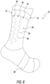
- the turbulence inducing features 38 preferably comprise a plurality of discrete spaced turbulators ( Fig. 8 ).
- the turbulators 38 are features that generally have a thickness greater than the thickness of the area around the turbulence-inducing features, so that the turbulators comprise relatively elevated areas that create turbulence, and preferably create a boundary layer 40 ( Fig. 4 ) between the appendaged covering 10 and the flow of air.
- the surface 39 of the turbulator 38 is also relatively rougher than the non-turbulator areas 41 of the sock 10.
- the third or rear zone 32 generally includes a surface 46 that is smoother than the surface second or side zone 28 to induce a smaller amount of air flow turbulence than is created in the second zone.
- the third zone 32 includes a thickened portion 44 disposed at the rear of the sock 10 which serves to help aerodynamically direct the air stream 52 at the rear of the sock 10 so that the air stream 52 flowing along one side of the leg merges more smoothly with the air flowing across the other side of the leg.
- the stocking 10 is a unitarily formed, preferably in a single process, from a single material. Through this process, there is no need to join dissimilar materials together as in the Spandex socks discussed above.
- the foot engaging first portion 14 typically resides within the interior of the shoe (not shown) being worn by the user. Because the foot engaging portion 14 resides within the shoe of the user, very little air flows directly over it during movement, such as when the user is riding the bicycle. For these reasons, the aerodynamics of the foot portion are generally not as important as the aerodynamic properties of the second leg-engaging portion.
- the foot engaging portion includes a toe portion 54.
- the toe portion 54 is disposed at the distal end of the foot engaging portion. From a manufacturing standpoint, the stocking 10 is typically made as a tube having two open ends. The open distal end is then folded over, with the distal end of the toe 54 being attached to the dorsal surface 56 of the foot engaging portion 14, so that a closed toe sock 10 results.
- the leg portion 16 of the sock 10 extends upwardly from the foot engaging portion 14, and generally comprises that portion of the sock 10 which typically resides exteriorly of the shoe and receives and engages the lower part of the user's leg.
- the leg portion 16 can be of any length and extend any desired distance up the user's leg. Because the leg portion provides superior aerodynamics as compared to the user's naked leg, it is aerodynamically advantageous to have a relatively longer length in the leg portion 16, which may extend 3 inches to 6 inches, 9 inches, or even a greater number of inches up the user's leg.
- leg portion 16 there may be advantages to extending the leg portion 16 all the way up to the interior of the user's pants, or possibly even employ the leg portion 16 to serve as pants for the user in a manner similar to pantyhose.
- This line of demarcation comprises a transition point 60.
- the transition point 60 between the foot engaging portion 14 and the leg engaging portion 16 does not require a seam, since the stocking is unitarily formed from the same material. Because the transition point 60 is seamless, there is no added thickness at the transition point 60.
- the transition point 60 has relevance since the sock 10 is knitted to form the foot-engaging portion 14 of the sock 10 differently than the leg portion 16.
- This lack of a seam provides design advantages to the manufacturer, and comfort advantages to the user.
- the design advantage provided to the manufacturer is that the lack of the seam, and the lack of any additional thickness therewith, enables the manufacturer to place the transition line anywhere that he/she chooses, without adding discomfort. Although discomfort would likely not increase even with a thickened seam if the thickened seam were placed exteriorly of the shoe, a thickened seam would likely cause discomfort if the seam were placed interiorly of the shoe. Since the present invention does not have a thickened seam, but rather a non-thickened transition area, the transition area can be placed interiorly of the shoe without adding discomfort to the user.
- the transition point 60 is advantageous to place the transition point 60 interiorly of the shoe, because that lengthens the leg engaging portion 16. Since the leg engaging portion 16 is designed to provide features, such as turbulators 38, which help the aerodynamic performance of the sock 10, the lengthening of the leg engaging portion 16 provides more area for the manufacturer to provide aerodynamically enhanced materials and features, to thereby help to improve the overall aerodynamic efficiency of the stockings 10.
- the surface 62 of the foot engaging portion 14 is generally smooth and does not include any turbulence-inducing features 38 such as ribs or turbulators 38.
- a smoother, flatter surface 62 is chosen, because it helps to enhance comfort, and to maintain the thinness of the sock 10.
- the dorsal surface 56 of the foot engaging portion includes a thickened dorsal portion 66.
- the thickened dorsal portion 66 is co-knitted into the material at this portion to provide a thickening of the sock 10, to provide additional padding.
- this thickened dorsal portion 66 is positioned under the point where the user's shoe is strapped. The placement of the thickened area 66 at that position is believed to add additional comfort to the user.
- the leg engaging portion 16 can include a plurality of micro-ribs 72 (shown in Fig. 1 ).
- the primary purpose of the micro-ribs 72 is to help the sock 10 stay upright and engaged onto the user's leg.
- the presently known Lycra socks even though ribbed, have a tendency to fall down on the user's leg, and not stay in their proper position.
- the socks 10 of the present invention can employ the micro-ribs 72 to create a sock which will stay properly positioned on the user's leg.
- a thickened portion 74 that includes additional elastic strength is disposed at the top of the leg portion 16, and helps to maintain the leg portion 16 upright, and properly positioned on the user's leg.
- the micro-ribs 72 extend circumferentially around the smooth first frontal zone 24, the side first 28A and second 28B turbulator containing zone 28, and most of the smooth rear zone 32.
- the size of the micro-ribs 72 are minimized (when compared to the ribs of the Lycra Socks) to minimize the turbulence induced by the micro-ribs 72.
- the smooth leg engaging front zone 24 is designed to embrace the air, without inducing more turbulence than necessary. Inducing turbulence on this smooth front engaging zone 24 does not aid in the aerodynamic efficiency.
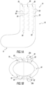
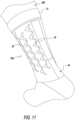
- the side turbulator containing zones 28A, 28B include three rows 78, 80, 82 of six discrete turbulators 38.
- These turbulators 38 are shown in the drawings ( Fig. 1A ) to include a front vertically arrayed first row 78, a middle vertically arrayed second row 80, and a rear vertically arrayed third row 82 of six individual discrete turbulators 38.
- Turbulators 38 take on the appearance that has similarities to a B2 Spirit Bomber as shown best in Fig. 6 with a pointed narrow leading end 86, and a wider trailing end 88 that comprises three rear-pointing arrow-shaped members.
- the turbulators 38 preferably each add about 1 to 1.25 millimeters of additional thickness to the base thickness of the socks 10. This additional thickness adds turbulence to the air flowing around the first and second sides 28A, 28B of the second zone 28, which introduces turbulence into the boundary layer.
- aerodynamic efficiency is improved, as the airflow is better able to remain attached to the sock 10 surface downstream, resulting in a reduction in the pressure wake behind the sock, as shown in Fig. 4 , when compared to a sock that does not include turbulators, as shown in Fig. 4A .
- a thickened rear member 50 is disposed approximately at 6 o'clock (180° from the front of the sock 10) which helps to pull together the air streams flowing around the respective left and right sides 280 of the user 286 sock 10, as shown in Fig. 4 .
- the sock 10 is made in a single knit process that is made from a single material.
- the single knitting process with a single material, one can place the turbulence-inducing features 38 wherever one wants to along the body of the sock 10, as it is all the same sock 10.
- the yarn material from which the sock is knitted comprises a nylon yarn.
- the nylon yarn comprises a Q-skin ® yarn that is manufactured by Fulgar SPA of Strada Casaloldo, 55, 46042 Castel Gloiso (MN)-Italy, whose website is www.fulgar.com .
- the Q-skin material is described as being a polyamide 6.6 fiber in which silver ions are inserted directly during the spinning process. The presence of the silver limits the bacterial growth, which helps to reduce odor.
- Fulgar states that the Q-skin material provides the wearer with breathability, freshness, hygiene, and comfort.
- the nylon material is preferably knit using a 200-needle Jacquard knitting machine (not shown).
- the Jacquard type knitting machine allows one to bring in and drop out additional needles of yarn so that as you are knitting the sock, one can change the thickness of the sock by changing the number of needles being used to vary the thickness or pattern of the sock. See www.xdknitmachinery.com.
- the material is knitted so that the turbulators 38 have approximately somewhere between 1.0 and 1.25 millimeters of additional thickness when compared to the rest of the sock.
- the turbulators 38 have approximately somewhere between 1.0 and 1.25 millimeters of additional thickness when compared to the rest of the sock.
- the number of needles one can vary the thickness, and by using a greater number of needles, one can increase the thickness of the material.
- the yarn itself is created by Fulgar, or some other yarn manufacturer, and then sent to a fabric manufacturer, who knits the yarn to form a piece of fabric, and then shapes or forms into a fabric item having a desired size and shape for the desired finished product, such as shirts or stockings.
- the foot-engaging first portion 14 of the sock 10 is generally knit to have a smooth exterior surface. In deciding the pattern, one tries to achieve a balance between flexibility, comfort, strength, and ability to hold the sock up on the leg. For the foot-engaging portion, one does not need to be overly concerned with holding the socks up, as they will naturally hold themselves onto the generally horizontally-disposed foot of the user.
- micro-ribs 72 are useful in holding the sock up onto the leg.
- preferably very small or "micro-ribs” are preferably used. Small ribs 72 are used because it is desired to provide the smoothest surface possible which still has enough ribs to enable the sock to hold up on the leg.
- FIGs. 3 and 4 show the leg-engaging portion 16 that is exposed to flowing air, and includes the turbulators 38, or aerodynamically enhancing the flow of air past the leg portion.
- the side zone 28 includes a first side turbulator-containing zone 28A and a second side turbulator-containing zone 28B.
- first and second side turbulator-containing zones 28A, 28B are generally similar.
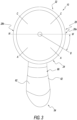
- line W-W ( Fig. 3 ) which comprises a laterally-extending diameter line which extends through the thickest part of the leg.
- the leg is somewhat oval shaped.
- the front zone 24 is designed to be a smooth air-engaging surface. As discussed above, the front smooth air-engaging zone 24 contains no turbulators 38, but does contain micro-ribs, which although detracting from the smoothness of the surface, enhance the sock by improving the sock's 10 ability to stay up and engage with the user's leg, especially when the sock 10 gets wet.
- the front zone 24 is defined generally between lines A-A and is disposed generally at the front of the leg.
- the front section 24 is preferably generally smooth, because the airflow around the front zone 24 is generally the laminar.
- first set of turbulators 38 should be positioned not at the widest point, W-W of the leg, but rather be disposed a little forwardly of the center line W-W. It has been found by the applicants, that the first turbulator is preferably located at about 20 degrees forward from the diameter line W-W at about the position of line B.
- the socks 10 By placing the turbulators 38 at about 20 degrees in front of the center line W-W, the socks 10 have a better ability to create turbulence in crosswinds and the like, or when the user has his/her leg canted at an angled position, and not straight forward.
- the second, or turbulator containing zone 28 is positioned in the areas between lines A and C, and the rear zone is the area generally between lines C-C ( Fig. 3 ).
- the turbulators include a first (forward) 78, second (middle) 80, and third (rearward) 82 array of vertically disposed discrete turbulators 38.
- Each of the arrays comprises six individual "stealth bomber" shaped turbulators 38.
- the row that has the greatest influence on the airflow is the first, or forward, set 78 of turbulators 38.
- the second 80 and third 82 rows of turbulators 38 also create turbulence, but do have as large of an impact on the airflow of the first row 78 of turbulators 38.
- the rear zone 32 of the sock 10 is generally smooth except that it should have a raised portion shown as the ribbon-shaped thickened rear member 44 that is disposed at the back center of the sock 10, approximately 180 degrees from the leading edge of the stocking 10. It has been found that placing a thickened portion 44 at the rear of the sock helps to improve airflow by discharging the air that flows off the back of the sock in the laminar matter, to thereby reduce turbulence at the rear of the sock 10.
- turbulence TR at the rear of the sock is a significant contributor to aerodynamic drag. By reducing this turbulence TR, one helps to significantly reduce aerodynamic drag.
- Fig. 4A it will be noted that the large turbulent zone TR extends behind the sock, which is much larger and more turbulent than the turbulent zone that exists behind the socks with the turbulator 38 ( Fig. 4 ).
- suction drag In order to increase aerodynamic efficiency, one wants to reduce the size of this suction drag area.
- the sock without the turbulator ( Fig. 4A ) has a larger suction drag area than the sock with the turbulators ( Fig. 4 ) and, as such, creates more suction drag, when compared to the sock of the present invention with a turbulator ( Fig. 4 ).
- the sock of the present invention is either on par or possibly significantly faster than the Lycra-type aerodynamic socks discussed above.
- One advantage is that, unlike the Lycra sock, the design and material of the present invention are significantly more likely to engage the leg, and not fall down during use, and especially when the sock gets wet.
- a further advantage is that the sock 10 of the present invention is believed to be much less expensive to produce than the two-piece Lycra sock. This can provide a significant cost advantage to the manufacturer, and possibly the user.
- FIG. 6 shows one of the turbulators 38 that, as described above, bears a top profile reminiscent of that of a Stealth bomber.
- the turbulator includes a leading point 86, and first and second leading edges 87 and 89, three rear-corner points 92, 94, and 96, and two interior corners 100 and 102.
- the three trailing corners 92, 94, and 96 form micro-vortices that want to curl over the surface to introduce energy into the flow of air thereover, which causes the air to want to stick down onto the surface.
- faster and higher flow rates cause the airstream to be much more difficult to separate from the surface than lower energy flow.
- the two interior corners at the back, 100 and 102 actually create a small suction that wants to pull the air flow down against the sock even more. These corners 100, 102 induce a little negative pressure that wants to turn the air down.
- the trailing edge center point 94 can actually form additional micro-vortices to help pull the airstream down onto the surface of the sock.
- the turbulators induce turbulence with the turbulators and because of the suction, that turbulence is held against the surface of the sock, and reducing the ability of the air flow to separate from the sock.
- Points 92, 94, and 96 create the turbulence, and interior corners 100 and 102 serve as suction vortices that hold down the flow.
- the turbulator 38 puts energy into the flow, to thereby reduce overall aerodynamic drag. Although you are probably adding about one or two percent of skin drag by the use of the turbulators 38, you are still reducing the suction and pressure drag by about as much as half at the rear (downwind) portion of the leg. The net result is that a little bit of investment in increased skin drag results in a significant savings of drag overall. It is believed that you are probably adding about three percent of skin friction drag while achieving a 15 percent savings.
- a very thin yarn should be used at the frontal area 24 of the sock and a relatively thicker yarn should be used to form the turbulators 38.
Landscapes
- Engineering & Computer Science (AREA)
- Textile Engineering (AREA)
- Socks And Pantyhose (AREA)
Claims (8)
- Aerodynamisch optimierte Körpergliedbedeckung (10), die einen ersten Abschnitt (14), der keiner signifikanten Luftströmung ausgesetzt ist, und einen zweiten Abschnitt (16) umfasst, der so positioniert ist, dass er in eine signifikant stärkere Luftströmung eingreift, wenn er auf einem sich bewegenden Körper (MB) platziert ist, wobei zumindest ein Teil des zweiten Abschnitts (16) einen aerodynamisch optimierten Bereich umfasst,wobei der aerodynamisch optimierte Bereich eine erste vordere Zone (24), eine zweite turbulenzinduzierende Zone (28) und eine dritte hintere Zone (32) umfasst, wobei die zweite Zone (28) zwischen der ersten (24) und der dritten (32) Zone angeordnet ist,wobei die erste Zone (24) so konfiguriert ist, dass sie eine relativ glatte Oberfläche aufweist, um eine relativ geringere Menge an Turbulenzen auf die vorbeiströmende Luft zu induzieren als die zweite Zone (28), wobei die zweite Zone (28) eine Oberfläche aufweist, die weniger glatt ist als die erste Zone (24),die zweite Zone mindestens zwei Reihen (78, 80, 82) von diskreten turbulenzinduzierenden Merkmalen (38) umfasst, die so konfiguriert sind, dass sie eine Grenzschicht (40) zum Induzieren von Turbulenzen in der an der zweiten Zone (28) vorbeiströmenden Luft erzeugen, dadurch gekennzeichnet, dass die dritte Zone (32) eine Oberfläche aufweist, die glatter ist als die zweite Zone (28), unddie dritte Zone (32) einen bandförmigen erhabenen Abschnitt (50) umfasst, der sich in einer Richtung erstreckt, die im Allgemeinen senkrecht zur Richtung der Luftströme ist, die während der Verwendung der Körpergliedbedeckung (10) an der zweiten Zone (28) vorbeiströmen, wobei der bandförmige erhabene Abschnitt (50) so konfiguriert und positioniert ist, dass er die Luftströme so lenkt, dass sie sich an der Rückseite der Körpergliedbedeckung (10) vereinigen.
- Körpergliedbedeckung nach Anspruch 1, wobei die turbulenzinduzierenden Merkmale (38) eine allgemein deltaförmige Form mit einem schmalen vorderen Ende (86) und einem relativ breiteren hinteren Ende (88) aufweisen.
- Körpergliedbedeckung nach Anspruch 2, wobei das hintere Ende (88) der turbulenzinduzierenden Merkmale (38) drei hintere Eckpunkte (92, 94, 96) und zwei innere Ecken (100, 102) aufweist.
- Körpergliedbedeckung nach einem der vorhergehenden Ansprüche, wobei die Körpergliedbedeckung (10), wenn sie auf einem Körper angeordnet ist, eine Aufwindseite und eine Abwindseite hat, die erste Zone (24) an der Aufwindseite der Körpergliedbedeckung (10) angeordnet ist und die dritte Zone (32) an der Abwindseite angeordnet ist.
- Körpergliedbedeckung nach Anspruch 4, wobei die Körpergliedbedeckung eine imaginäre Ebene (W-W) umfasst, die sich seitlich zur Richtung des Luftstroms erstreckt und die Körpergliedbedeckung (10) im Wesentlichen halbiert, wobei die turbulenzinduzierenden Merkmale auf der zweiten Zone (28) zwischen etwa 45 Grad in Windrichtung der Ebene (W-W) und 45 Grad in Windrichtung der Ebene (W-W) angeordnet sind.
- Körpergliedbedeckung nach Anspruch 5, wobei die turbulenzinduzierenden Merkmale (38) zwischen etwa 25 Grad in Aufwindrichtung der Ebene (W-W) und 25 Grad in Abwindrichtung der Ebene (W-W) angeordnet sind.
- Körpergliedbedeckung nach einem der vorhergehenden Ansprüche, wobei der erste Abschnitt (14) und der zweite Abschnitt (16) in einem Übergangsbereich zusammentreffen, der keine Naht enthält.
- Körpergliedbedeckung nach einem der vorhergehenden Ansprüche, wobei die turbulenzinduzierenden Merkmale (38) die Dicke der zweiten Zone (28) um etwa 0,9 bis 1,5 mm, vorzugsweise um etwa 1,0 bis 1,25 mm, erhöhen.
Applications Claiming Priority (2)
| Application Number | Priority Date | Filing Date | Title |
|---|---|---|---|
| US202163225486P | 2021-07-24 | 2021-07-24 | |
| US202163231416P | 2021-08-10 | 2021-08-10 |
Publications (3)
| Publication Number | Publication Date |
|---|---|
| EP4122341A1 EP4122341A1 (de) | 2023-01-25 |
| EP4122341B1 true EP4122341B1 (de) | 2025-06-25 |
| EP4122341C0 EP4122341C0 (de) | 2025-06-25 |
Family
ID=82702934
Family Applications (1)
| Application Number | Title | Priority Date | Filing Date |
|---|---|---|---|
| EP22186594.2A Active EP4122341B1 (de) | 2021-07-24 | 2022-07-22 | Aerodynamisch verbesserte anhängeverkleidungen |
Country Status (2)
| Country | Link |
|---|---|
| US (1) | US20230029392A1 (de) |
| EP (1) | EP4122341B1 (de) |
Family Cites Families (11)
| Publication number | Priority date | Publication date | Assignee | Title |
|---|---|---|---|---|
| US5033116A (en) * | 1989-07-24 | 1991-07-23 | Descente Ltd. | Clothing for reducing fluid resistance |
| US5887280A (en) * | 1995-03-10 | 1999-03-30 | Waring; John | Wearable article for athlete with vortex generators to reduce form drag |
| US7941869B2 (en) * | 2007-02-09 | 2011-05-17 | Nike, Inc. | Apparel with reduced drag coefficient |
| US10918141B2 (en) * | 2009-06-24 | 2021-02-16 | Nike, Inc. | Drag-reducing exercise equipment |
| US20150230552A1 (en) * | 2014-02-19 | 2015-08-20 | Met 1 Life Inc. | Compression sock for prevention and treatment of foot and ankle injuries |
| US10238156B2 (en) * | 2015-01-13 | 2019-03-26 | Under Armour, Inc. | Suit for athletic activities |
| GB2537815A (en) * | 2015-04-20 | 2016-11-02 | Smart Aero Tech Ltd | Low drag garment |
| GB2537816B (en) * | 2015-04-20 | 2018-06-20 | Endura Ltd | Low drag garment |
| US10716340B2 (en) * | 2015-05-27 | 2020-07-21 | Nike, Inc. | System and device for affecting drag properties of an object |
| US10264834B2 (en) * | 2016-03-25 | 2019-04-23 | Nike, Inc. | Foam nodes for creating stand off on apparel items |
| GB2555570A (en) * | 2016-10-18 | 2018-05-09 | Smart Aero Tech Limited | Low drag garment |
-
2022
- 2022-07-22 EP EP22186594.2A patent/EP4122341B1/de active Active
- 2022-07-23 US US17/871,911 patent/US20230029392A1/en not_active Abandoned
Also Published As
| Publication number | Publication date |
|---|---|
| US20230029392A1 (en) | 2023-01-26 |
| EP4122341C0 (de) | 2025-06-25 |
| EP4122341A1 (de) | 2023-01-25 |
Similar Documents
| Publication | Publication Date | Title |
|---|---|---|
| US9386810B2 (en) | Thermal energy dissipating garment with scalloped vents | |
| EP3076818B1 (de) | Gestricktes band mit integrierter belüftung | |
| US7941869B2 (en) | Apparel with reduced drag coefficient | |
| US20060277652A1 (en) | Cycling upper garment | |
| US20070015439A1 (en) | Shaping pant | |
| US20160000150A1 (en) | High performance garments | |
| CN108471825B (zh) | 具有整体擦拭区域的服装 | |
| EP4122341A1 (de) | Aerodynamisch verbesserte anhängeverkleidungen | |
| WO2021046148A1 (en) | Placket and collar stabilization | |
| CN214759212U (zh) | 一种防后腰部下掉的裤子 | |
| CN201563648U (zh) | 无缝骑行上衣 | |
| US20260015776A1 (en) | Textile configured to promote cooling | |
| US20260015777A1 (en) | Textile configured to promote cooling | |
| US20260013583A1 (en) | Textile configured to promote cooling | |
| CN222397099U (zh) | 一种抓绒外套 | |
| JPS595686Y2 (ja) | 競技用衣服 | |
| CN221307317U (zh) | 一种吸汗防黏运动衣 | |
| CN217117562U (zh) | 一种吸汗快干针织背心 | |
| CN224165755U (zh) | 一种透气t恤 | |
| CN216453427U (zh) | 一种运动休闲短袖 | |
| CN210248433U (zh) | 一种舒适型涤棉t恤衫 | |
| US20250160444A1 (en) | Collared sleeve partial undergarment | |
| WO2026015662A2 (en) | Textile configured to promote cooling | |
| CN212014509U (zh) | 一种防粘身发汗骑行服 | |
| US7131146B2 (en) | Stay-put slip |
Legal Events
| Date | Code | Title | Description |
|---|---|---|---|
| PUAI | Public reference made under article 153(3) epc to a published international application that has entered the european phase |
Free format text: ORIGINAL CODE: 0009012 |
|
| STAA | Information on the status of an ep patent application or granted ep patent |
Free format text: STATUS: THE APPLICATION HAS BEEN PUBLISHED |
|
| AK | Designated contracting states |
Kind code of ref document: A1 Designated state(s): AL AT BE BG CH CY CZ DE DK EE ES FI FR GB GR HR HU IE IS IT LI LT LU LV MC MK MT NL NO PL PT RO RS SE SI SK SM TR |
|
| STAA | Information on the status of an ep patent application or granted ep patent |
Free format text: STATUS: REQUEST FOR EXAMINATION WAS MADE |
|
| 17P | Request for examination filed |
Effective date: 20230724 |
|
| RBV | Designated contracting states (corrected) |
Designated state(s): AL AT BE BG CH CY CZ DE DK EE ES FI FR GB GR HR HU IE IS IT LI LT LU LV MC MK MT NL NO PL PT RO RS SE SI SK SM TR |
|
| GRAP | Despatch of communication of intention to grant a patent |
Free format text: ORIGINAL CODE: EPIDOSNIGR1 |
|
| STAA | Information on the status of an ep patent application or granted ep patent |
Free format text: STATUS: GRANT OF PATENT IS INTENDED |
|
| INTG | Intention to grant announced |
Effective date: 20250131 |
|
| GRAS | Grant fee paid |
Free format text: ORIGINAL CODE: EPIDOSNIGR3 |
|
| GRAA | (expected) grant |
Free format text: ORIGINAL CODE: 0009210 |
|
| STAA | Information on the status of an ep patent application or granted ep patent |
Free format text: STATUS: THE PATENT HAS BEEN GRANTED |
|
| AK | Designated contracting states |
Kind code of ref document: B1 Designated state(s): AL AT BE BG CH CY CZ DE DK EE ES FI FR GB GR HR HU IE IS IT LI LT LU LV MC MK MT NL NO PL PT RO RS SE SI SK SM TR |
|
| REG | Reference to a national code |
Ref country code: GB Ref legal event code: FG4D |
|
| REG | Reference to a national code |
Ref country code: CH Ref legal event code: EP |
|
| REG | Reference to a national code |
Ref country code: CH Ref legal event code: EP |
|
| REG | Reference to a national code |
Ref country code: IE Ref legal event code: FG4D |
|
| REG | Reference to a national code |
Ref country code: DE Ref legal event code: R096 Ref document number: 602022016331 Country of ref document: DE |
|
| U01 | Request for unitary effect filed |
Effective date: 20250722 |
|
| U07 | Unitary effect registered |
Designated state(s): AT BE BG DE DK EE FI FR IT LT LU LV MT NL PT RO SE SI Effective date: 20250728 |
|
| U20 | Renewal fee for the european patent with unitary effect paid |
Year of fee payment: 4 Effective date: 20250902 |
|
| PG25 | Lapsed in a contracting state [announced via postgrant information from national office to epo] |
Ref country code: NO Free format text: LAPSE BECAUSE OF FAILURE TO SUBMIT A TRANSLATION OF THE DESCRIPTION OR TO PAY THE FEE WITHIN THE PRESCRIBED TIME-LIMIT Effective date: 20250925 Ref country code: GR Free format text: LAPSE BECAUSE OF FAILURE TO SUBMIT A TRANSLATION OF THE DESCRIPTION OR TO PAY THE FEE WITHIN THE PRESCRIBED TIME-LIMIT Effective date: 20250926 |
|
| PG25 | Lapsed in a contracting state [announced via postgrant information from national office to epo] |
Ref country code: HR Free format text: LAPSE BECAUSE OF FAILURE TO SUBMIT A TRANSLATION OF THE DESCRIPTION OR TO PAY THE FEE WITHIN THE PRESCRIBED TIME-LIMIT Effective date: 20250625 |
|
| PG25 | Lapsed in a contracting state [announced via postgrant information from national office to epo] |
Ref country code: RS Free format text: LAPSE BECAUSE OF FAILURE TO SUBMIT A TRANSLATION OF THE DESCRIPTION OR TO PAY THE FEE WITHIN THE PRESCRIBED TIME-LIMIT Effective date: 20250925 |
|
| PG25 | Lapsed in a contracting state [announced via postgrant information from national office to epo] |
Ref country code: IS Free format text: LAPSE BECAUSE OF FAILURE TO SUBMIT A TRANSLATION OF THE DESCRIPTION OR TO PAY THE FEE WITHIN THE PRESCRIBED TIME-LIMIT Effective date: 20251025 |
|
| PG25 | Lapsed in a contracting state [announced via postgrant information from national office to epo] |
Ref country code: SM Free format text: LAPSE BECAUSE OF FAILURE TO SUBMIT A TRANSLATION OF THE DESCRIPTION OR TO PAY THE FEE WITHIN THE PRESCRIBED TIME-LIMIT Effective date: 20250625 |
|
| PG25 | Lapsed in a contracting state [announced via postgrant information from national office to epo] |
Ref country code: CZ Free format text: LAPSE BECAUSE OF FAILURE TO SUBMIT A TRANSLATION OF THE DESCRIPTION OR TO PAY THE FEE WITHIN THE PRESCRIBED TIME-LIMIT Effective date: 20250625 |
|
| PG25 | Lapsed in a contracting state [announced via postgrant information from national office to epo] |
Ref country code: PL Free format text: LAPSE BECAUSE OF FAILURE TO SUBMIT A TRANSLATION OF THE DESCRIPTION OR TO PAY THE FEE WITHIN THE PRESCRIBED TIME-LIMIT Effective date: 20250625 |
|
| PG25 | Lapsed in a contracting state [announced via postgrant information from national office to epo] |
Ref country code: SK Free format text: LAPSE BECAUSE OF FAILURE TO SUBMIT A TRANSLATION OF THE DESCRIPTION OR TO PAY THE FEE WITHIN THE PRESCRIBED TIME-LIMIT Effective date: 20250625 |
|
| PG25 | Lapsed in a contracting state [announced via postgrant information from national office to epo] |
Ref country code: ES Free format text: LAPSE BECAUSE OF FAILURE TO SUBMIT A TRANSLATION OF THE DESCRIPTION OR TO PAY THE FEE WITHIN THE PRESCRIBED TIME-LIMIT Effective date: 20250625 |
|
| REG | Reference to a national code |
Ref country code: CH Ref legal event code: H13 Free format text: ST27 STATUS EVENT CODE: U-0-0-H10-H13 (AS PROVIDED BY THE NATIONAL OFFICE) Effective date: 20260224 |
|
| PG25 | Lapsed in a contracting state [announced via postgrant information from national office to epo] |
Ref country code: MC Free format text: LAPSE BECAUSE OF FAILURE TO SUBMIT A TRANSLATION OF THE DESCRIPTION OR TO PAY THE FEE WITHIN THE PRESCRIBED TIME-LIMIT Effective date: 20250625 |
|
| PG25 | Lapsed in a contracting state [announced via postgrant information from national office to epo] |
Ref country code: CH Free format text: LAPSE BECAUSE OF NON-PAYMENT OF DUE FEES Effective date: 20250731 |
|
| PLBE | No opposition filed within time limit |
Free format text: ORIGINAL CODE: 0009261 |
|
| STAA | Information on the status of an ep patent application or granted ep patent |
Free format text: STATUS: NO OPPOSITION FILED WITHIN TIME LIMIT |
|
| REG | Reference to a national code |
Ref country code: CH Ref legal event code: L10 Free format text: ST27 STATUS EVENT CODE: U-0-0-L10-L00 (AS PROVIDED BY THE NATIONAL OFFICE) Effective date: 20260507 |