EP4121303B1 - Laufstreifenprofil eines fahrzeugreifens - Google Patents
Laufstreifenprofil eines fahrzeugreifens Download PDFInfo
- Publication number
- EP4121303B1 EP4121303B1 EP20820867.8A EP20820867A EP4121303B1 EP 4121303 B1 EP4121303 B1 EP 4121303B1 EP 20820867 A EP20820867 A EP 20820867A EP 4121303 B1 EP4121303 B1 EP 4121303B1
- Authority
- EP
- European Patent Office
- Prior art keywords
- groove
- profile
- extension
- rubber
- tread
- Prior art date
- Legal status (The legal status is an assumption and is not a legal conclusion. Google has not performed a legal analysis and makes no representation as to the accuracy of the status listed.)
- Active
Links
Images



Classifications
-
- B—PERFORMING OPERATIONS; TRANSPORTING
- B60—VEHICLES IN GENERAL
- B60C—VEHICLE TYRES; TYRE INFLATION; TYRE CHANGING; CONNECTING VALVES TO INFLATABLE ELASTIC BODIES IN GENERAL; DEVICES OR ARRANGEMENTS RELATED TO TYRES
- B60C11/00—Tyre tread bands; Tread patterns; Anti-skid inserts
- B60C11/03—Tread patterns
- B60C11/13—Tread patterns characterised by the groove cross-section, e.g. for buttressing or preventing stone-trapping
- B60C11/1307—Tread patterns characterised by the groove cross-section, e.g. for buttressing or preventing stone-trapping with special features of the groove walls
-
- B—PERFORMING OPERATIONS; TRANSPORTING
- B60—VEHICLES IN GENERAL
- B60C—VEHICLE TYRES; TYRE INFLATION; TYRE CHANGING; CONNECTING VALVES TO INFLATABLE ELASTIC BODIES IN GENERAL; DEVICES OR ARRANGEMENTS RELATED TO TYRES
- B60C11/00—Tyre tread bands; Tread patterns; Anti-skid inserts
- B60C11/03—Tread patterns
- B60C11/0306—Patterns comprising block rows or discontinuous ribs
- B60C11/0309—Patterns comprising block rows or discontinuous ribs further characterised by the groove cross-section
-
- B—PERFORMING OPERATIONS; TRANSPORTING
- B60—VEHICLES IN GENERAL
- B60C—VEHICLE TYRES; TYRE INFLATION; TYRE CHANGING; CONNECTING VALVES TO INFLATABLE ELASTIC BODIES IN GENERAL; DEVICES OR ARRANGEMENTS RELATED TO TYRES
- B60C11/00—Tyre tread bands; Tread patterns; Anti-skid inserts
- B60C11/03—Tread patterns
- B60C11/04—Tread patterns in which the raised area of the pattern consists only of continuous circumferential ribs, e.g. zig-zag
- B60C11/042—Tread patterns in which the raised area of the pattern consists only of continuous circumferential ribs, e.g. zig-zag further characterised by the groove cross-section
-
- B—PERFORMING OPERATIONS; TRANSPORTING
- B60—VEHICLES IN GENERAL
- B60C—VEHICLE TYRES; TYRE INFLATION; TYRE CHANGING; CONNECTING VALVES TO INFLATABLE ELASTIC BODIES IN GENERAL; DEVICES OR ARRANGEMENTS RELATED TO TYRES
- B60C11/00—Tyre tread bands; Tread patterns; Anti-skid inserts
- B60C11/03—Tread patterns
- B60C11/13—Tread patterns characterised by the groove cross-section, e.g. for buttressing or preventing stone-trapping
- B60C11/1307—Tread patterns characterised by the groove cross-section, e.g. for buttressing or preventing stone-trapping with special features of the groove walls
- B60C2011/1338—Tread patterns characterised by the groove cross-section, e.g. for buttressing or preventing stone-trapping with special features of the groove walls comprising protrusions
Definitions
- the invention relates to a tread pattern of a vehicle tire with profile elements separated from one another by grooves, wherein the profile elements separated by a groove are delimited in the radial direction outwards by a radially outer surface forming the ground contact surface and towards the groove by a profile element flank forming a groove wall, and wherein the grooves are delimited in the radial direction inwards by a groove base and on both sides of the groove base by a groove wall which extends in the radial direction from the groove base to the radially outer surface of the profile element delimited by it, wherein in the profile element flanks delimiting the groove and each forming a different groove wall of the groove, a rubber rib extending in the direction of extension of the groove is formed.
- Such pneumatic vehicle tires are known.
- the tread profiles of pneumatic vehicle tires are formed with grooves delimited by profile elements. It is known to form commercial vehicle tires with circumferential grooves which are delimited by profile ribs or by profile block rows, wherein the profile block rows are formed from profile block elements delimited by transverse grooves.
- the grooves allow water and mud to be absorbed and drained away when rolling on the road surface.
- the grooves also allow stones, debris and other foreign particles to be absorbed, which can penetrate into the bottom of the groove.
- JP H03 135804 A It is known to form a groove in a tread of a vehicle tire, which is narrow in a first radial extension section extending from the groove base to far outwards near the radially outer surface of the profile elements.
- a first groove wall is formed with a sudden outward offset, thereby widening the groove.
- a rib is formed in the second groove wall, which extends in individual extension sections of the groove towards the groove in the direction of the first groove wall up to over the step of the first groove wall formed by the sudden offset.
- the invention is therefore based on the object of enabling a tread pattern of a vehicle tire - in particular for use in commercial vehicles or vans - in which adjacent raised profile elements separated from one another by grooves are formed, which enable sufficient water to be absorbed, and to provide better protection against the penetration of stones down to the groove bottom over the entire profile element extension.
- the object is achieved according to the invention by the design of a tread profile of a vehicle tire with profile elements separated from one another by grooves, wherein the profile elements separated by a groove are delimited in the radial direction outwards by a radially outer surface forming the ground contact surface and towards the groove by a profile element flank forming a groove wall, and wherein the grooves are delimited in the radial direction inwards by a groove base and on both sides of the groove base by a groove wall which extends in the radial direction from the groove base to the radially outer surface of the profile element delimited by it, wherein in the profile element flanks delimiting the groove and each forming a different groove wall of the groove, a rubber rib extending in the direction of extension of the groove is formed, according to the features of claim 1, in which the rubber rib formed in one groove wall is formed in a different radial position of the vehicle tire than the rubber rib formed in the other groove wall, wherein the two rubber ribs each extend over the entire extension length of the
- This design makes it possible for the two rubber ribs formed in the groove walls to be positioned one above the other along the entire extension of the profile element delimiting the groove and to be extended in their direction of extension to the opposite profile element delimiting the groove to a position that overlaps with the other rubber rib.
- a tread profile according to the features of claim 3, wherein the two rubber ribs are each formed at their extension end pointing towards the other profile element flank with a - in particular semicircular - rounded cutting contour in the cross-sectional planes formed perpendicular to the extension direction of the groove.
- a tread profile according to the features of claim 4, wherein the groove is formed with a radial extension section of the extension height H 3 measured in the radial direction R, in which the two groove walls formed by the profile element flanks extend parallel in the cross-sectional planes formed perpendicular to the extension direction of the grooves, wherein this extension section is the narrowest radial extension section of the groove, in which the groove width B is constant with 2 mm ⁇ B ⁇ 4 mm, and wherein the two rubber ribs are formed within this radial extension section.
- a tread profile according to the features of claim 5, wherein the groove is formed with a radially outer extension section which extends radially outwards to the radially outer surface, in which the groove is formed along its radial outward extension with increasing groove width B.
- the larger opening in the radially outer section allows the advantages of good wet braking properties and the good abrasion performance due to a smaller void in the lower narrow extension section to be optimally combined.
- the rubber ribs in the narrow extension section overcompensate for the disadvantages for stone catching caused by the large groove opening in the radially outer extension section of the groove.
- a tread profile according to the features of claim 6, wherein the groove is a circumferential groove.
- the grooves of the vehicle tire that are particularly susceptible to stone catching are provided with the sealing effect and thus the vehicle tire as a whole is particularly protected.
- a tread profile according to the features of claim 7, wherein the profile elements delimiting the groove are each part of a profile band, wherein in particular the profile elements of at least one profile band are profile block elements of a profile block row.
- a tread profile according to the features of claim 8 wherein the two rubber ribs are designed with a distance d 1 from one another of 1 mm ⁇ d 1 ⁇ 3 mm.
- This design means that the distance is sufficiently large to avoid contact between the rubber ribs and the resulting damage or abrasion, and sufficiently small to ensure a good sealing effect of the labyrinth seal and to prevent stones from penetrating.
- each of the two rubber ribs is designed with its extension end pointing away from its profile element flank at a distance d 2 from the other profile element flank of 1 mm ⁇ d 2 ⁇ 2 mm. This design makes it easy to ensure a distance between the rubber ribs that is sufficiently small for the labyrinth seal to be closed securely, without impairing the shape retention and demoldability.
- a tread profile according to the features of claim 10, wherein the rubber rib is designed with an extension width h measured in the radial direction R of the tire with 1.5 mm ⁇ h ⁇ 3 mm.
- the extension width h is sufficiently large to provide sufficient resistance to unwanted abrasion by stones penetrating up to the rubber rib without filling the groove so much with rubber material that the wet braking properties are undesirably impaired.
- a tread profile according to the features of claim 11, wherein the pair of rubber ribs is designed with a constant distance d 1 from one another along the extension of the groove with a changed course of the radial position - in particular in a wave-like manner. This can prevent the wet properties from changing suddenly when the vehicle tire is worn until it reaches a rubber rib.
- the Figures 1 to 8 show a tread pattern of the pneumatic tire of a commercial vehicle.
- the tread pattern is - as in Fig.1 is shown - with the circumferential ribs 1, 6 and profile block rows 2, 3, 4, 5 arranged next to one another in the axial direction A of the pneumatic vehicle tire and spaced apart from one another by circumferential grooves 7, 8, 9, 10, 23 and extending over the entire circumference of the pneumatic vehicle tire.
- the two circumferential ribs 1 and 6 are formed in the two tire shoulders and thus form the profile bands of the tire shoulders.
- the profile block rows 2, 3, 4 and 5 are formed, which form the middle profile bands.
- the profile block row 2 is separated from the circumferential rib 1 in the axial direction A by the circumferential groove 7.
- the profile block row 2 and the profile block row 3 are separated from one another in the axial direction A by the circumferential groove 8.
- the profile block row 3 and the profile block row 4 are separated from one another in the axial direction A by the circumferential groove 9.
- the profile block row 4 and the profile block row 5 are separated from one another in the axial direction A by the circumferential groove 10.
- the profile block row 5 and the circumferential rib 6 are separated from one another in the axial direction A by the circumferential groove 23.
- the profile block rows 2, 3, 4 and 5 are each formed in a known manner from profile block elements arranged one behind the other around the circumference of the pneumatic vehicle tire, which are each separated from one another by transverse grooves 11.
- the tread block row 2 is formed from tread block elements 12 arranged one behind the other in the circumferential direction U around the circumference of the pneumatic vehicle tire and separated from one another by transverse grooves 11.
- the tread block row 3 is formed from tread block elements 13 arranged one behind the other in the circumferential direction U around the circumference of the pneumatic vehicle tire and separated from one another by transverse grooves 11.
- the tread block row 4 is formed from tread block elements 14 arranged one behind the other in the circumferential direction U around the circumference of the pneumatic vehicle tire and each separated from one another by transverse grooves 11.
- the tread block row 5 is formed from tread block elements 15 arranged one behind the other in the circumferential direction U around the circumference of the pneumatic vehicle tire and separated from one another by transverse grooves 11.
- the transverse grooves 11 of the profile block row 2 extend from the circumferential groove 7 through the profile block row 2 to the circumferential groove 8.
- the transverse grooves 11 of the profile block row 3 extend from the circumferential groove 8 through the profile block row 3 to the circumferential groove 9.
- the transverse grooves 11 of the profile block row 4 extend from the circumferential groove 9 through the profile block row 4 to the circumferential groove 10.
- the transverse grooves 11 of the Tread block row 5 extends from the circumferential groove 10 through the tread block row 5 to the circumferential groove 23.
- the circumferential ribs 1 and 6 as well as the profile block elements 12, 13, 14 and 15 of the profile block rows 2, 3, 4 and 5 are - as shown in the example of the profile block elements 13 and 14 in Fig.3 and Fig.4 shown - is limited outwards in the radial direction R of the pneumatic vehicle tire by a radially outer surface 16 forming the road contact surface.
- the transverse grooves 11 and the circumferential grooves 7, 8, 9, 10 and 23 are each delimited in the radial direction R inwards in a known manner by a groove base 22 and on both sides of the groove base 22 by a groove wall which extends from the groove base 22 to the radially outer surface 16 in the radial direction R outwards and thereby forms the respective flank pointing towards the transverse or circumferential groove of the profile element delimited by the transverse or circumferential groove.
- the circumferential grooves 6, 7, 8, 9, 10 are delimited on both sides of the groove base 22 by groove walls 17 and 18, which extend from the groove base 22 in the radial direction R of the pneumatic vehicle tire outwards to the radially outer surface 16 and end there.
- the groove wall 17 forms the flanks of the profile block elements 13 of the profile block row 3 delimited by the circumferential groove 9 and the groove wall 18 forms the flanks of the profile block elements 14 of the profile block row 4 delimited on the other side by the circumferential groove 9.
- the circumferential groove 9 is formed with a groove depth T, which starts from the radially outer surface 16 of the profile block elements 13 and 14 delimited by the circumferential groove 9 and is measured in the radial direction R inwards to the deepest point of the groove base 22, and which corresponds to the profile depth.
- the groove walls 17 and 18 are formed in the cross-sectional planes which are formed perpendicular to the main extension direction of the circumferential groove 9 and, in the case of circumferential grooves, are the cutting planes which contain the tire axis, along a radial extension section of the extension height H 3 measured in the radial direction R with cutting contours running parallel to one another.
- the groove walls 17 and 18 are formed in this extension section of the extension height H 3 with a distance B from one another which forms the groove width in this extension section.
- the extension section of the extension height H 3 is formed with a width B which is between 2 mm ⁇ B ⁇ 4 mm.
- a rubber rib 19 extending over the entire circumference of the pneumatic vehicle tire is formed, which rises from the groove wall 17 in the direction of the groove wall 18 into the circumferential groove 9 and extends with its elevation in the axial direction A of the pneumatic vehicle tire to over half the groove width and thus over a position at a distance B/2 from the groove wall 17 and ends there with its extension end 21 pointing towards the groove wall 18 at a distance d 2 from the groove wall 18.
- a rubber rib 20 is formed which extends over the entire circumference of the pneumatic vehicle tire and which rises from the groove wall 18 in the direction of the groove wall 17 into the circumferential groove 9 and thereby extends with its elevation in the axial direction A of the Vehicle pneumatic tire extends over half the groove width and thus over a position at a distance B/2 from the groove wall 18 and ends there with its extension end 21 pointing towards the groove wall 17 at a distance d 2 from the groove wall 17.
- the rubber ribs 19 and 20 extend along the entire extent of the circumferential groove 9 with their main extension direction in the circumferential direction U of the vehicle tire.
- the rubber rib 19 extends along the entire extent of the profile block element flank of a profile block element 13 formed by the groove wall 17.
- the rubber rib 20 extends along the entire extent of the profile block element flank of a profile block element 14 formed by the groove wall 18.
- the distance d 2 is designed with d 2 ⁇ B/2.
- Both rubber ribs 19 and 20 are each formed along their entire extension in the circumferential direction U of the pneumatic vehicle tire with a rib width h measured in the radial direction R of the pneumatic vehicle tire.
- the rib width h of the rubber rib 19 is formed in the groove wall 17 with its maximum value.
- the rib width h of the rubber rib 20 is formed in the groove wall 18 with its maximum value.
- the two rubber ribs 19 and 20 formed in the circumferential groove 9 are positioned offset from each other in the radial direction R of the vehicle pneumatic tire.
- the rubber rib 20 is positioned in the radial direction R of the pneumatic vehicle tire outside the position of the rubber rib 19, wherein the two rubber ribs 19 and 20 are positioned offset from one another in such a way that, despite axial overlap of their extension ends in the region of the middle of the groove width, they are positioned at a distance d 1 from one another.
- the rubber rib 19 positioned closer to the groove bottom 22 is positioned at a distance H 2 from the groove bottom 22 measured in the radial direction R of the pneumatic vehicle tire, wherein the distance H 2 is measured in the groove wall 17.
- the extension width h of the rubber ribs 19, 20 is selected to be 1.5mm ⁇ h ⁇ 3mm.
- the distance d 1 between the adjacent rubber ribs 19, 20 is 1mm ⁇ d 1 ⁇ 3mm is selected.
- the distance d 2 between the rubber rib 19 or 20 and the opposite groove wall 18 or 17 is designed with 1mm ⁇ d 2 ⁇ 2 mm.
- the extension height H 1 is designed with H 1 ⁇ T/2.
- the formation of a circumferential groove according to the invention is shown and explained using the example of a circumferential groove 7, which separates a circumferential rib 1 formed in one tire shoulder from the tread block row 2.
- the circumferential groove 7 is also designed with a groove depth T.
- the two groove walls 17 and 18 are designed in the cutting planes perpendicular to the main extension direction of the circumferential groove 7 with the cutting contour of the groove walls 17 and 18 aligned parallel to one another at a constant distance and thus with a substantially constant groove width B.
- the extension height H 3 is designed with H 3 ⁇ T.
- the circumferential groove 7 is designed along the radial extension of the circumferential groove 7 up to the radially outer surface 16 of the adjacent circumferential rib 1 and the adjacent profile block row 2 with a continuously increasing groove width B.
- a rubber rib 19 is formed in the groove wall 17 and a rubber rib 20 is formed in the groove wall 18 in an analogous manner, which - as already stated in connection with the other exemplary embodiments - are formed with the rib width h, with a distance d 1 from one another and with a distance d 2 from the respective opposite groove wall.
- the rubber rib 19 arranged closer to the groove base 22 is arranged at a distance H 2 from the groove base 22 measured in the radial direction R of the pneumatic vehicle tire.
- the radially outer rubber rib 20 is formed with at least half of its rib width h measured in the radial direction R still within the extension section of the extension height H 3 .
- the rubber ribs 19 and 20 are each formed along their entire extension over the circumference of the pneumatic vehicle tire in a constant radial position of the tire with a rib width h formed in the radial direction, with their distance d 1 to one another and with a distance d 2 to the respective opposite groove wall.
- Fig.9 an alternative design of the rubber ribs 19 and 20 is shown using the example of a circumferential groove 9.
- the rubber ribs 19 and 20 are also formed along their entire extension direction over the circumference of the pneumatic vehicle tire with a constant distance d 1 from each other, with a constant rib width h measured in the radial direction R in the groove wall, with a constant distance d 2 from the opposite groove wall, with a minimum distance H 2 from the groove base 22 and within the extension section of the extension height H 1 and within the extension section of the extension height H 3.
- the radial position of the rubber ribs 20 and 19 changes along their extension over the entire circumference of the pneumatic vehicle tire.
- this pair of rubber ribs 19 and 20 arranged one above the other is designed with a wave-like course of their radial positioning along the extension of the vehicle tire.
Landscapes
- Engineering & Computer Science (AREA)
- Mechanical Engineering (AREA)
- Tires In General (AREA)
Description
- Die Erfindung betrifft ein Laufstreifenprofil eines Fahrzeugreifens mit durch Rillen voneinander getrennten Profilelementen, wobei die durch eine Rille getrennten Profilelemente in radialer Richtung nach außen hin durch eine die Bodenkontaktfläche bildende radial äußere Oberfläche und zur Rille hin jeweils durch eine eine Rillenwand bildende Profileelementflanke begrenzt werden und wobei die Rillen in radialer Richtung nach innen hin durch einen Rillengrund und beiderseits des Rillengrundes jeweils durch eine Rillenwand begrenzt werden, welche sich in radialer Richtung ausgehend vom Rillengrund bis zur radial äußeren Oberfläche des von ihr begrenzten Profilelementes erstreckt, wobei in den die Rille begrenzenden, jeweils eine andere Rillenwand der Rille bildenden Profilelementflanken jeweils eine in Erstreckungsrichtung der Rille erstreckte Gummirippe ausgebildet ist.
- Derartige Fahrzeugluftreifen sind bekannt. Die Laufstreifenprofile von Fahrzeugluftreifen werden mit von Profilelementen begrenzten Rillen ausgebildet. Es ist dabei bekannt, Nutzfahrzeugreifen mit Umfangsrillen auszubilden, welche durch Profilrippen oder durch Profilblockreihen begrenzt sind, wobei die Profilblockreihen aus durch Querrillen begrenzten Profilblockelementen ausgebildet sind.
- Die Rillen ermöglichen dabei die Aufnahme und die Ableitung von Wasser und Matsch beim Abrollen auf der Straßenoberfläche. Gerade bei Nutzfahrzeugreifen ermöglichen die Rillen dabei auch die Aufnahme von Steinen und Geröll und anderen Fremdpartikeln, welche bis in den Rillengrund eindringen können. Dabei besteht auch die Möglichkeit, dass derartige Fremdpartikel in das Gummimaterial in den Rillengrundbereich eindringen können. Daher ist es wünschenswert, insbesondere bei Einsatz derartiger Fahrzeugluftreifen mit erhöhtem Steinfangrisiken, das Eindringen von Steinen möglichst zu vermeiden. Hierdurch kann die Beschädigung des Rillengrundes und ein mögliches Eindringen der Fremdkörper bis in den Gürtelbereich vermieden werden.
- Beispielsweise aus der
US 26 61 041 A ist es bekannt, in beiden Rillenwänden einer Rille in gleicher identischer Höhenposition, jedoch in Rillenerstreckungsrichtung in alternierender Abfolge hintereinander zylindrische Erhebungen auszubilden, die sich jeweils von der einen Rillenwand in Richtung zur anderen hin erstrecken, jedoch im Abstand von der anderen Rillenwand enden. Die Ausbildung kann dabei in begrenztem Umfang das Eindringen von Steinen behindern, allerdings ist zwischen den in alternierender Abfolge ausgebildeten zylindrischen Erhebungen noch ausreichend offener mit offenem Zugang zum Rillengrund, der es ermöglicht, dass dennoch auch größere Fremdkörper eindringen können. Ebenso kann zwischen den zylindrischen Erhebungen und der gegenüberliegenden Wand ein Eindringen von Fremdkörpern nicht vermieden werden. - Aus der
US 9,033,013 B2 - Aus der
DE1505020A1 ist es bekannt, in Umfangsrillen, welche Umfangsrippen begrenzen, wechselweise Erstreckungsabschnitte der Umfangsrillen mit in den Rillenwänden in radialer Richtung des Reifens übereinander angeordneten rippenförmigen Abschnitten auszubilden. Dabei ist in einem Erstreckungsabschnitt der Rille der oberhalb angeordnete rippenförmige Abschnitt in der einen Rillenwand und der unterhalb angeordnete in der anderen Rillenwand ausgebildet und in einem anschließenden Erstreckungsabschnitt genau entgegengesetzt der oberhalb angeordnete in der anderen Wand und der unterhalb angeordnete in der einen Rillenwand. Auch diese in Erstreckungsrichtung der Rille alternierende Abfolge von übereinander angeordneten rippenförmigen Abschnitten bewirkt lediglich, dass zwei rippenförmige Abschnitte in einzelnen Umfangserstreckungsabschnitten des Reifens Wirkung zeigen könnten. In den Abschnitten des Übergangs der hintereinander abfolgend angeordneten Rippenabschnitte sind jedoch Abschnitte mit offenem Durchgang bis zum Rillengrund hin gegeben, die es ermöglichen, dass Steine und sonstige Fremdpartikel einfach eindringen und bis zum Rillengrund hindurch gelangen können. Zusätzlich sind derartige in den Bereich des Rillengrundes eingedrungene Steine und Fremdartikel dann durch die benachbarten Abschnitte an einem Verlassen des Reifenprofiles gehindert, so dass bei derartigen Ausbildungen die Fremdkörper regelrecht im unteren Bereich des Rillengrundes gefangen sind und hierdurch der Rillengrund beschädigt werden kann. - Aus der
JP H03 135804 A - Der Erfindung liegt daher die Aufgabe zugrunde, ein Laufstreifenprofil eines Fahrzeugreifens - insbesondere für den Einsatz bei Nutzfahrzeugen oder Vanfahrzeugen - zu ermöglichen, bei dem benachbarte, durch Rillen voneinander getrennte erhabene Profilelemente ausgebildet sind, die es ermöglichen ausreichend Wasser aufzunehmen, abzuleiten und über die gesamte Profilelementerstreckung hinweg einen besseren Schutz gegen Eindringen von Steinen bis zum Rillengrund zu ermöglichen.
- Die Aufgabe wird erfindungsgemäß durch die Ausbildung eines Laufstreifenprofils eines Fahrzeugreifens mit durch Rillen voneinander getrennten Profilelementen, wobei die durch eine Rille getrennten Profilelemente in radialer Richtung nach außen hin durch eine die Bodenkontaktfläche bildende radial äußere Oberfläche und zur Rille hin jeweils durch eine eine Rillenwand bildende Profilelementflanke begrenzt werden und wobei die Rillen in radialer Richtung nach innen hin durch einen Rillengrund und beiderseits des Rillengrundes jeweils durch eine Rillenwand begrenzt wird, welche sich in radialer Richtung ausgehend vom Rillengrund bis zur radial äußeren Oberfläche des von ihr begrenzten Profilelementes erstreckt, wobei in den die Rille begrenzenden, jeweils eine andere Rillenwand der Rille bildenden Profilelementflanken jeweils eine in Erstreckungsrichtung der Rille erstreckte Gummirippe ausgebildet ist, gemäß den Merkmalen von Anspruch 1 gelöst, bei dem die in der einen Rillenwand gebildete Gummirippe in anderer radialer Position des Fahrzeugreifens ausgebildet ist als die in der anderen Rillenwand ausgebildete Gummirippe, wobei die beiden Gummirippen sich jeweils über die gesamte Erstreckungslänge der Profilelementflanke erstrecken und wobei jede dieser beiden Gummirippen jeweils längs ihrer gesamten Erstreckungslänge von derjenigen Profilelementflanke, in welcher sie ausgebildet ist, in die Rille hinein in Richtung zur anderen Profilelementflanke bis mindestens zur Mitte der Rillenbreite in dieser radialen Position der Rille erstreckt und dort, in der Rille mit Abstand zu den Profilelementflanken endet.
- Durch diese Ausbildung wird ermöglicht, dass längs der gesamten Erstreckung des die Rille begrenzenden Profilelementes die beiden in den Rillenwänden ausgebildeten Gummirippen übereinander positioniert ausgebildet und dabei in ihrer Erstreckungsrichtung zum jeweils gegenüberliegenden, die Rille begrenzenden Profilelement bis in eine Position erstreckt sind, dass eine Überlappung mit der jeweils anderen Gummirippe erfolgt. Auf diese Weise ist längs der gesamten Erstreckung des Profilelementes eine Art Labyrinth-Dichtung innerhalb der Rille geschaffen, die es ermöglicht, ein Eindringen von Steinen oder sonstigen spitzen Fremdkörpern weitgehend zu verhindern und dennoch den Rillencharakter zur Aufnahme von Wasser und zur Ableitung von Wasser aufrecht zu erhalten, wobei die Rille mit einer in radialer Richtung ausgehend vom Rillengrund bis zur radial äußeren Oberfläche der angrenzenden Profilelemente gemessenen Rillentiefe T ausgebildet ist und die beiden Gummirippen innerhalb eines ausgehend vom Rillengrund nach radial außen hin gemessenen radialen Erstreckungsbereiches der Erstreckungshöhe H1 =T/2 ausgebildet sind.. Somit kann auf diese Weise eine hohe Sicherheit gegen Eindringen von Fremdkörpern bei gleichzeitiger Aufrechterhaltung der Aufnahme und Ableitung von Wasser mit einfachen Mitteln umgesetzt werden und dies auch bei sehr schmalen Rillen. Dabei kann in einfacher Weise sichergestellt werden, dass die Rille in radialer Richtung außerhalb der Gummirippen soweit schließen kann, dass ein Eindringen von Steinen minimiert wird.
- In dieser Weise können auch besonders anfällige Nutzfahrzeugreifen und Vanreifen in einfacher Weise zuverlässig gegen Eindringen von Steinen gerüstet werden.
- Besonders vorteilhaft ist die Ausbildung eines Laufstreifenprofils gemäß den Merkmalen von Anspruch 2, wobei die beiden Gummirippen jeweils in einer radialen Position außerhalb einer ausgehend vom Rillengrund nach radial außen hin gemessenen Höhe H2 = 3mm ausgebildet sind. Hierdurch kann in einfacher Weise sichergestellt werden, dass bei der Verformung des Reifens durch die Gummirippen entstehende Spannungsspitzen in ausreichend großem Abstand zum Rillengrund entstehen. Die Möglichkeit der Entstehung von Groove Cracks kann hierdurch zusätzlich minimiert werden.
- Besonders vorteilhaft zur einfachen Ausformung beim Reifenbauprozess ist die Ausbildung eines Laufstreifenprofils gemäß den Merkmalen von Anspruch 3, wobei die beiden Gummirippen jeweils an ihrem zur anderen Profilelementflanke hinweisenden Erstreckungsende mit einer in den senkrecht zur Erstreckungsrichtung der Rille gebildeten Querschnittsebenen mit einer - insbesondere halbkreisförmig - abgerundeten Schnittkontur ausgebildet sind.
- Besonders vorteilhaft zur Erzielung einer optimalen Dichtwirkung ist die Ausbildung eines Laufstreifenprofils gemäß den Merkmalen von Anspruch 4, wobei die Rille mit einem radialen Erstreckungsabschnitt der in radialer Richtung R gemessenen Erstreckungshöhe H3 ausgebildet ist, in welchem die beiden durch die Profilelementflanken gebildeten Rillenwände in den senkrecht zur Erstreckungsrichtung der Rillen gebildeten Querschnittsebenen parallel erstreckt sind, wobei dieser Erstreckungsabschnitt der schmalste radiale Erstreckungsabschnitt der Rille ist, in welchem die Rillenbreite B konstant mit 2mm ≤ B ≤ 4mm ausgebildet ist, und wobei die beiden Gummirippen innerhalb dieses radialen Erstreckungsabschnitts ausgebildet sind.
- Besonders vorteilhaft ist die Ausbildung eines Laufstreifenprofils gemäß den Merkmalen von Anspruch 5, wobei die Rille mit einem radial äußeren Erstreckungsabschnitt ausgebildet ist, welcher sich nach radial außen bis zur radial äußeren Oberfläche erstreckt, in welchem die Rille längs ihrer radial Erstreckung nach außen hin mit zunehmender Rillenbreite B ausgebildet ist. Hierdurch können durch die größere Öffnung im radial äußeren Abschnitt die Vorteile für gute Nassbremseigenschaften und die guter Abriebsleistung durch geringeres Void im unteren engen Erstreckungsabschnitt optimal kombiniert umgesetzt werden. Die Gummirippen im schmalen Erstreckungsabschnitt überkompensieren dabei die durch die große Rillenöffnung im radial äußeren Erstreckungsabschnitt der Rille bedingten Nachteile für das Steinefangen.
- Besonders vorteilhaft ist die Ausbildung eines Laufstreifenprofils gemäß den Merkmalen von Anspruch 6, wobei die Rille eine Umfangsrille ist. Hierdurch werden gerade die für Steinefangen besonders anfälligen Rillen des Fahrzeugreifens mit der Dichtwirkung ausgestattet und somit der Fahrzeugreifen insgesamt besonders geschützt.
- Besonders vorteilhaft ist die Ausbildung eines Laufstreifenprofils gemäß den Merkmalen von Anspruch 7, wobei die die Rille begrenzenden Profilelemente jeweils Teil eines Profilbandes sind, wobei insbesondere die Profilelemente zumindest eines Profilbandes Profilblockelemente einer Profilblockreihe sind.
- Besonders vorteilhaft ist die Ausbildung eines Laufstreifenprofils gemäß den Merkmalen von Anspruch 8, wobei die beiden Gummirippen mit einem Abstand d1 zueinander mit 1mm ≤ d1 ≤ 3mm ausgebildet sind. Durch diese Ausbildung ist der Abstand ausreichend groß, um Kontakt zwischen den Gummirippen und hierdurch bedingte Beschädigungen oder Abrieb zu vermeiden und ausreichend klein um eine gute Dichtwirkung der Labyrinth-Dichtung sicherszustellen und ein eindringen von Steinen zu vermeiden. Besonders vorteilhaft ist die Ausbildung eines Laufstreifenprofils gemäß den Merkmalen von Anspruch 9, wobei die jede der beiden Gummirippen jeweils mit ihrem von ihrer Profilelementflanke wegweisenden Erstreckungsende mit einem Abstand d2 zur anderen Profilelementflanke ausgebildet ist mit 1mm ≤ d2 ≤ 2mm ausgebildet sind. Durch diese Ausbildung kann in einfacher Weise ein für sicheres Schließen der Labyrinth-Dichtung ausreichend kleiner Abstand zwischen den Gummirippen sichergestellt werden ohne die Formhaltbarkeit und Entformungsfähigkeit zu beeinträchtigen.
- Besonders vorteilhaft ist die Ausbildung eines Laufstreifenprofils gemäß den Merkmalen von Anspruch 10, wobei die Gummirippe mit einer in radialer Richtung R des Reifens gemessenen Erstreckungsbreite h mit 1,5mm ≤ h ≤ 3mm ausgebildet. Die Erstreckungsbreite h ist dabei ausreichend groß, um ausreichenden Widerstand gegen unerwünschtes Abreiben durch bis zur Gummirippe eindringende Steine bereitzustellen ohne dabei die Rille so stark mit Gummimaterial zu füllen, dass die Nassbremseigenschaften unerwünscht beeinträchtigt werden.
- Besonders vorteilhaft ist die Ausbildung eines Laufstreifenprofils gemäß den Merkmalen von Anspruch 11, wobei das Paar von Gummirippen bei konstant zueinander ausgebildetem Abstand d1 längs der Erstreckung der Rille mit - insbesondere wellenförmig - verändertem Verlauf der radialen Position ausgebildet ist. Somit kann verhindert werden, dass bei Abrieb des Fahrzeugreifens bis Erreichen einer Gummirippe schlagartig Nässeeigenschaften geändert werden.
- Die Erfindung wird im Folgenden anhand der in den
Figuren 1 bis 9 dargestellten Ausführungsbeispiele näher erläutert. Hierin zeigen - Fig.1
- einen Umfangsabschnitt eines Laufstreifenprofils eines Fahrzeugreifens in Draufsicht,
- Fig.2
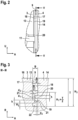
- eine vergrößerte Detaildarstellung II der Draufsicht von
Fig.1 , - Fig.3
- das Laufstreifenprofil von
Fig.1 in Schnittdarstellung gemäß Schnitt III-III vonFig.1 , - Fig.4
- das Laufstreifenprofil von
Fig.1 in Schnittdarstellung gemäß Schnitt IV-IV vonFig. 1 , - Fig.5
- das Laufstreifenprofil von
Fig.1 in Schnittdarstellung gemäß Schnitt V-V vonFig.1 , - Fig.6
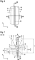
- eine vergrößerte Detaildarstellung des Details VI-VI von
Fig.1 , - Fig.7
- das Laufstreifenprofil von
Fig.1 in Schnittdarstellung gemäß Schnitt VII-VII vonFig. 1 , - Fig.8
- das Laufstreifenprofil von
Fig.1 in Schnittdarstellung gemäß Schnitt VIII-VIII vonFig.1 und - Fig.9
- vergrößerte Perspektivendarstellung des Abschnittes des Laufstreifenprofils von
Fig. 1 mit alternativer Ausbildung der Gummirippen einer Umfangsrille. - Die
Figuren 1 bis 8 zeigen ein Laufstreifenprofil des Fahrzeugluftreifens eines Nutzfahrzeuges. Das Laufstreifenprofil ist - wie inFig.1 dargestellt ist - mit den in axialer Richtung A des Fahrzeugluftreifens nebeneinander angeordneten und jeweils durch Umfangsrillen 7, 8, 9, 10, 23 voneinander beabstandeten und über den gesamten Umfang des Fahrzeugluftreifen erstreckten Umfangsrippen 1, 6 und Profilblockreihen 2, 3, 4, 5 ausgebildet. Die beiden Umfangsrippen 1 und 6 sind dabei in den beiden Reifenschultern ausgebildet und bilden somit die Profilbänder der Reifenschultern. In axialer Richtung A zwischen den beiden Umfangsrippen 1 und 6 sind die Profilblockreihen 2, 3,4 und 5 ausgebildet, die die mittleren Profilbänder bilden. - Wie in
Fig.1 dargestellt ist, ist dabei die Profilblockreihe 2 in axialer Richtung A von der Umfangsrippe 1 durch die Umfangsrille 7 getrennt. Die Profilblockreihe 2 und die Profilblockreihe 3 sind in axialer Richtung A voneinander durch die Umfangsrille 8 getrennt. Die Profilblockreihe 3 und die Profilblockreihe 4 sind in axialer Richtung A durch die Umfangsrille 9 voneinander getrennt. Die Profilblockreihe 4 und die Profilblockreihe 5 sind in axialer Richtung A durch die Umfangsrille 10 voneinander getrennt. Die Profilblockreihe 5 und die Umfangsrippe 6 sind in axialer Richtung A durch die Umfangsrille 23 voneinander getrennt. - Die Profilblockreihen 2, 3, 4 und 5 sind dabei jeweils in bekannter Weise aus über den Umfang des Fahrzeugluftreifens hintereinander angeordneten Profilblockelementen ausgebildet, welche jeweils durch Querrillen 11 voneinander getrennt sind.
- Dabei ist die Profilblockreihe 2 aus über den Umfang des Fahrzeugluftreifens in Umfangsrichtung U hintereinander angeordneten Profilblockelementen 12 ausgebildet, welche durch Querrillen 11 voneinander getrennt sind. Die Profilblockreihe 3 ist aus über den Umfang des Fahrzeugluftreifens in Umfangsrichtung U hintereinander angeordneten Profilblockelementen 13 ausgebildet, welche durch Querrillen 11 voneinander getrennt sind. Die Profilblockreihe 4 ist aus über den Umfang des Fahrzeugluftreifens in Umfangsrichtung U hintereinander angeordneten Profilblockelementen 14 ausgebildet, welche jeweils durch Querrillen 11 voneinander getrennt sind. Die Profilblockreihe 5 ist aus über den Umfang des Fahrzeugluftreifens in Umfangsrichtung U hintereinander angeordneten Profilblockelementen 15 ausgebildet, welche durch Querrillen 11 voneinander getrennt sind.
- Die Querrillen 11 der Profilblockreihe 2 erstrecken sich dabei ausgehend von der Umfangsrille 7 durch die Profilblockreihe 2 hindurch bis zur Umfangsrille 8. Die Querrillen 11 der Profilblockreihe 3 erstrecken sich ausgehend von der Umfangsrille 8 durch die Profilblockreihe 3 hindurch bis zur Umfangsrille 9. Die Querrillen 11 der Profilblockreihe 4 erstrecken sich ausgehend von der Umfangsrille 9 durch die Profilblockreihe 4 hin durch bis zur Umfangsrille 10. Die Querrillen 11 der Profilblockreihe 5 erstrecken sich ausgehend von der Umfangsrille 10 durch die Profilblockreihe 5 hindurch bis zur Umfangsrille 23.
- Die Umfangsrippen 1 und 6 sowie die Profilblockelemente 12, 13, 14 und 15 der Profilblockreihen 2, 3, 4 und 5 sind - wie am Beispiel der Profilblockelemente 13 und 14 in
Fig.3 undFig. 4 dargestellt ist - in radialer Richtung R des Fahrzeugluftreifens nach außen hin durch eine die Straßenkontaktoberfläche bildende radial äußere Oberfläche 16 begrenzt. - Die Querrillen 11 sowie die Umfangsrillen 7, 8, 9, 10 und 23 sind in radialer Richtung R nach innen hin in bekannter Weise jeweils durch einen Rillengrund 22 begrenzt und beiderseits des Rillengrundes 22 jeweils durch eine Rillenwand, welche sich ausgehend vom Rillengrund 22 bis zur radial äußeren Oberfläche 16 in radialer Richtung R nach außen hin erstreckt und dabei die jeweilige zur Quer- bzw. Umfangsrille hinweisenden Flanke des durch die Quer- bzw. Umfangsrille begrenzten Profilelementes bildet.
- Wie in
Fig. 2 und 3 am Beispiel der Umfangsrille 9 dargestellt ist, sind die Umfangsrillen 6, 7, 8, 9, 10 dabei beiderseits des Rillengrundes 22 mit Rillenwänden 17 und 18 begrenzt, welche sich ausgehend vom Rillengrund 22 in radialer Richtung R des Fahrzeugluftreifens nach außen hin bis zur radial äußeren Oberfläche 16 erstrecken und dort enden. Am Beispiel der Umfangsrille 9 bildet die Rillenwand 17 jeweils die Flanken der Profilblockelemente 13 der durch die Umfangsrille 9 begrenzten Profilblockreihe 3 und die Rillenwand 18 die Flanken der Profilblockelemente 14 der zur anderen Seite hin von der Umfangsrille 9 begrenzten Profilblockreihe 4. - Die Umfangsrille 9 ist dabei mit einer ausgehend von der radial äußeren Oberfläche 16 der durch die Umfangsrille 9 begrenzten Profilblockelemente 13 und 14 in radialer Richtung R nach innen hin bis zum tiefsten Punkt des Rillengrundes 22 gemessenen Rillentiefe T ausgebildet, welche der Profiltiefe entspricht.
- In den
Figuren 2 bis 5 ist die Ausbildung einer erfindungsgemäßen Umfangsrille am Beispiel einer Umfangsrille 9 dargestellt und erläutert, welche eine Profilblockreihe 3 von einer Profilblockreihe 4 trennt. - Die Rillenwände 17 und 18 sind in den Querschnittebenen, welche senkrecht zur Haupterstreckungsrichtung der Umfangsrille 9 gebildet werden und bei Umfangsrillen diejenigen Schnittebenen sind, welche die Reifenachse beinhalten, längs eines radialen Erstreckungsabschnitt der in radialer Richtung R gemessenen Erstreckungshöhe H3 mit parallel zueinander verlaufenden Schnittkonturen ausgebildet. Die Rillenwände 17 und 18 sind in diesem Erstreckungsabschnitt der Erstreckungshöhe H3 mit einem Abstand B zueinander ausgebildet, welcher die Rillenbreite in diesem Erstreckungsabschnitt bildet. Der Erstreckungsabschnitt der Erstreckungshöhe H3 ist dabei mit einer Breite B ausgebildet, welche zwischen 2mm ≤ B ≤ 4 mm beträgt.
- Im dargestellten Ausführungsbeispiel der
Figuren 3 und4 ist H3 = T gewählt. - Wie in den
Figuren 3 und4 dargestellt ist, ist innerhalb eines radialen Erstreckungsabschnittes der Höhe H1 = T/2, welche ausgehend vom Rillengrund 22 nach radial außen gemessen wird, in der Rillenwand 17, welche die Profilblockelementreihe 13 begrenzt, eine über den gesamten Umfang des Fahrzeugluftreifens erstreckte Gummirippe 19 ausgebildet, welche sich ausgehend von der Rillenwand 17 in Richtung zur Rillenwand 18 in die Umfangsrille 9 hinein erhebt und sich dabei mit ihrer Erhebung in axialer Richtung A des Fahrzeugluftreifens bis über die Hälfte der Rillenbreite und somit über eine Position im Abstand B/2 von der Rillenwand 17 hinweg erstreckt und dort mit ihrem zur Rillenwand 18 weisenden Erstreckungsende 21 im Abstand d2 von der Rillenwand 18 endet. In analoger Weise ist innerhalb dieses radialen Erstreckungsabschnittes der Höhe H1 = T/2, welche ausgehend vom Rillengrund 22 nach radial außen gemessen wird, in der Rillenwand 18, welche die Profilblockelementreihe 14 begrenzt, eine über den gesamten Umfang des Fahrzeugluftreifens erstreckte Gummirippe 20 ausgebildet, welche sich ausgehend von der Rillenwand 18 in Richtung zur Rillenwand 17 in die Umfangsrille 9 hinein erhebt und sich dabei mit ihrer Erhebung in axialer Richtung A des Fahrzeugluftreifens bis über die Hälfte der Rillenbreite und somit über eine Position im Abstand B/2 von der Rillenwand 18 hinweg erstreckt und dort mit ihrem zur Rillenwand 17 weisenden Erstreckungsende 21 im Abstand d2 von der Rillenwand 17 endet. Die Gummirippen 19 und 20 erstrecken sich dabei längs der gesamten Erstreckung der Umfangsrille 9 mit ihrer Haupterstreckungsrichtung in Umfangsrichtung U des Fahrzeugreifen. Die Gummirippe 19 erstreckt sich dabei jeweils längs der gesamten Erstreckung der durch die Rillenwand 17 gebildeten Profilblockelementflanke eines Profilblockelementes 13. Die Gummirippe 20 erstreckt sich dabei jeweils längs der gesamten Erstreckung der durch die Rillenwand 18 gebildeten Profilblockelementflanke eines Profilblockelementes 14. Der Abstand d2 ist mit d2 < B/2 ausgebildet. - Beide Gummirippen 19 bzw. 20 sind längs ihrer gesamten Erstreckung in Umfangsrichtung U des Fahrzeugluftreifens jeweils mit einer in radialer Richtung R des Fahrzeugluftreifens gemessenen Rippenbreite h ausgebildet. Die Rippenbreite h der Gummirippe 19 ist in der Rillenwand 17 mit ihrem Maximalwert ausgebildet. Die Rippenbreite h der Gummirippe 20 ist in der Rillenwand 18 mit ihrem Maximalwert ausgebildet.
- Die beiden in der Umfangsrille 9 ausgebildeten Gummirippen 19 und 20 sind in radialer Richtung R des Fahrzeugluftreifens versetzt zueinander positioniert. So ist - wie in den
Figuren 3 und4 dargestellt - die Gummirippe 20 in radialer Richtung R des Fahrzeugluftreifens außerhalb der Position der Gummirippe 19 positioniert, wobei die beiden Gummirippen 19 und 20 derart versetzt zueinander positioniert sind, dass sie trotz axialer Überlappung ihrer Erstreckungsenden im Bereich der Mitte der Rillenbreite mit einem Abstand d1 zueinander positioniert sind. Wie inFig. 3 und4 dargestellt ist, ist die näher zum Rillengrund 22 positionierte Gummirippe 19 dabei in einem in radialer Richtung R des Fahrzeugluftreifens gemessenen Abstand H2 vom Rillengrund 22 positioniert, wobei der Abstand H2 in der Rillenwand 17 gemessen wird. - Die Erstreckungsbreite h der Gummirippen 19, 20 ist mit 1,5mm ≤ h ≤ 3mm gewählt ausgebildet. Der Abstand d1 zwischen den benachbarten Gummirippen 19, 20 ist mit 1mm ≤ d1 ≤ 3mm gewählt ausgebildet. Der Abstand d2 zwischen der Gummirippe 19 bzw. 20 und der jeweils gegenüber liegenden Rillenwand 18 bzw. 17 ist mit 1mm ≤ d2 < 2 mm ausgebildet.
- Die Erstreckungshöhe H1 ist mit H1 ≤ T/2 ausgebildet. Die Erstreckungshöhe H2 ist mit H2 ≥ 3mm ausgebildet. Im dargestellten Ausführungsbeispiel ist H2 = 3mm gewählt.
- In den
Figuren 6 bis 8 ist die Ausbildung einer erfindungsgemäßen Umfangsrille am Beispiel einer Umfangsrille 7 dargestellt und erläutert, welche eine in der einen Reifenschulter ausgebildete Umfangsrippe 1 von der Profilblockreihe 2 trennt. Wie denFiguren 6 bis 8 entnommen werden kann, sind auch bei diesem Ausführungsbeispiel die Umfangsrille 7 mit einer Rillentiefe T ausgebildet. Ebenso sind bei dieser Ausbildung innerhalb eines in radialer Richtung R ausgehend vom Rillengrund 22 gemessenen Erstreckungsabschnitts der Erstreckungshöhe H3 die beiden Rillenwände 17 und 18 in den Schnittebenen senkrecht zur Haupterstreckungsrichtung der Umfangsrille 7 mit in konstantem Abstand parallel zueinander ausgerichtetem Schnittkonturverlauf der Rillenwände 17 und 18 und somit mit einer im wesentlichen konstanten Rillenbreite B ausgebildet ist. Im dargestellten Ausführungsbeispiel ist die Erstreckungshöhe H3 mit H3 < T ausgebildet. Radial außerhalb des Erstreckungsabschnitt der Erstreckungshöhe H3 ist die Umfangsrille 7 längs der radialen Erstreckung der Umfangsrille 7 bis zur radial äußeren Oberfläche 16 der angrenzenden Umfangsrippe 1 und der angrenzenden Profilblockreihe 2 mit kontinuierlich zunehmender Rillenbreite B ausgebildet. - Wie in den
Figuren 7 und8 zu erkennen ist, sind innerhalb des Erstreckungsabschnitts der Erstreckungshöhe H1 und innerhalb des Erstreckungsabschnitt der Erstreckungshöhe H3 in analoger Weise in der Rillenwand 17 eine Gummirippe 19 und in der Rillenwand 18 eine Gummirippe 20 ausgebildet, welche - wie bereits im Zusammenhang mit den anderen Ausführungsbeispielen angegeben - mit der Rippenbreite h, mit Abstand d1 zueinander und mit Abstand d2 zur jeweils gegenüber liegenden Rillenwand ausgebildet sind. Die näher zum Rillengrund 22 hin angeordnete Gummirippe 19 ist in radialer Richtung R des Fahrzeugluftreifens gemessenem Abstand H2 zum Rillengrund 22 angeordnet. Wie inFig. 7 zu erkennen ist, ist dabei die radial äußere Gummirippe 20 mit mindestens der Hälfte ihrer in radialer Richtung R gemessenen Rippenbreite h noch innerhalb der Erstreckungsabschnittes der Erstreckungshöhe H3 ausgebildet. - In den oben dargestellten Ausführungsbeispielen sind die Gummirippen 19 und 20 jeweils längs ihrer gesamten Erstreckung über den Umfang des Fahrzeugluftreifens hinweg in gleichbleibender radialer Position des Reifens ausgebildet mit in radialer Richtung ausgebildeten Rippenbreite h, mit ihrem Abstand d1 zueinander und mit Abstand d2 zur jeweils gegenüberliegenden Rillenwand.
- In
Fig.9 ist am Beispiel einer Umfangsrille 9 eine alternative Ausbildung der Gummirippen 19 und 20 dargestellt. Dabei sind die Gummirippen 19 und 20 auch in dieser Ausbildung längs ihrer gesamten Erstreckungsrichtung über den Umfang des Fahrzeugluftreifens mit konstantem Abstand d1 zueinander, mit konstanter in radialer Richtung R gemessenen Rippenbreite h in der Rillenwand, mit konstantem Abstand d2 zur gegenüberliegenden Rillenwand, mit Mindestabstand H2 zum Rillengrund 22 und innerhalb des Erstreckungsabschnittes der Erstreckungshöhe H1 und innerhalb des Erstreckungsabschnittes der Erstreckungshöhe H3 ausgebildet. Allerdings verändert sich bei dieser Ausbildung die radiale Position der Gummirippen 20 und 19 längs ihrer Erstreckung über den gesamten Umfang des Fahrzeugluftreifens hinweg. Im dargestellten Ausführungsbeispiel ist, wie inFig.9 zu erkennen ist, dieses Paar von übereinander angeordneten Gummirippen 19 und 20 dabei mit einem längs der Erstreckung des Fahrzeugreifens wellenförmig verlaufendem Verlauf ihrer radialen Positionierung ausgebildet. -
- 1
- Umfangsrippe
- 2
- Blockreihe
- 3
- Blockreihe
- 4
- Blockreihe
- 5
- Blockreihe
- 6
- Umfangsrippe
- 7
- Umfangsrille
- 8
- Umfangsrille
- 9
- Umfangsrille
- 10
- Umfangsrille
- 11
- Querrille
- 12
- Profilblockelement
- 13
- Profilblockelement
- 14
- Profilblockelement
- 15
- Profilblockelement
- 16
- Radial äußere Oberfläche
- 17
- Rillenwand
- 18
- Rillenwand
- 19
- Rippe
- 20
- Rippe
- 21
- Erstreckungsende
- 22
- Rillengrund
Claims (11)
- Laufstreifenprofil eines Fahrzeugreifens mit durch Rillen (7,8,9,10,23) voneinander getrennten Profilelementen (1,12,13,14,15,6), wobei die durch eine Rille (9,7) getrennten Profilelemente (13,14,1,12) in radialer Richtung R nach außen hin durch eine, die Bodenkontaktfläche bildende radial äußere Oberfläche (16) und zur Rille (9,7) hin jeweils durch eine eine Rillenwand (17,18) bildende Profileelementflanke begrenzt werden und wobei die Rillen (9,7) in radialer Richtung R nach innen hin durch einen Rillengrund (22) und beiderseits des Rillengrundes (22) jeweils durch eine Rillenwand (17,18) begrenzt wird, welche sich in radialer Richtung R ausgehend vom Rillengrund (22) bis zur radial äußeren Oberfläche (16) des von ihr begrenzten Profilelementes (13,14,1,12) erstreckt,wobei in den die Rille (9,7) begrenzenden, jeweils eine andere Rillenwand (17,18) der Rille (9,7) bildenden Profilelementflanken jeweils eine in Erstreckungsrichtung der Rille (9,7) erstreckte Gummirippe (20,19) ausgebildet ist,wobei die in der einen Rillenwand (17) gebildete Gummirippe (19) in anderer radialer Position des Fahrzeugreifens ausgebildet ist als die in der anderen Rillenwand (18) ausgebildete Gummirippe (20),dadurch gekennzeichnet,dass die beiden Gummirippen (19,20) sich jeweils über die gesamte Erstreckungslänge der Profilelementflanke erstrecken und wobei jede dieser beiden Gummirippen(19,20) jeweils längs ihrer gesamten Erstreckungslänge von derjenigen Profilelementflanke, in welcher sie ausgebildet ist, in die Rille (9,7) hinein in Richtung zur anderen Profilelementflanke bis mindestens zur Mitte der Rillenbreite in dieser radialen Position der Rille (9,7) erstreckt und dort in der Rille (9,7) mit Abstand d2 zu den Profilelementflanken endet unddass die Rille (9,7) mit einer in radialer Richtung R ausgehend vom Rillengrund (22) bis zur radial äußeren Oberfläche (16) der angrenzenden Profilelemente (13,14,1,12) gemessenen Rillentiefe T ausgebildet ist und die beiden Gummirippen (19,20) innerhalb eines ausgehend vom Rillengrund (22) nach radial außen hin gemessenen radialen Erstreckungsbereiches der Erstreckungshöhe H1 =T/2 ausgebildet sind.
- Laufstreifenprofil gemäß den Merkmalen von Anspruch 1,
wobei die beiden Gummirippen (19,20) jeweils in einer radialen Position außerhalb einer ausgehend vom Rillengrund (22) nach radial außen hin gemessenen Höhe H2 = 3mm ausgebildet sind. - Laufstreifenprofil gemäß den Merkmalen von einem oder mehreren der vorangegangenen Ansprüche,
wobei die beiden Gummirippen (19,20) jeweils an ihrem zur anderen Profilelementflanke hinweisenden Erstreckungsende (21) mit einer in den senkrecht zur Erstreckungsrichtung der Rille (9,7) gebildeten Querschnittsebenen mit einer - insbesondere halbkreisförmig - abgerundeten Schnittkontur ausgebildet sind. - Laufstreifenprofil gemäß den Merkmalen von einem oder mehreren der vorangegangenen Ansprüche,
wobei die Rille (9,7) mit einem radialen Erstreckungsabschnitt der in radialer Richtung R gemessenen Erstreckungshöhe H3 ausgebildet ist, in welchem die beiden durch die Profilelementflanken gebildeten Rillenwände (17,18) in den senkrecht zur Erstreckungsrichtung der Rillen (9,7) gebildeten Querschnittsebenen parallel erstreckt sind, wobei dieser Erstreckungsabschnitt der schmalste radiale Erstreckungsabschnitt der Rille (9,7) ist, in welchem die Rillenbreite B konstant mit 2mm ≤ B ≤ 4mm ausgebildet ist, und wobei die beiden Gummirippen (19,20) innerhalb dieses radialen Erstreckungsabschnitts ausgebildet sind. - Laufstreifenprofil gemäß den Merkmalen von Anspruch 4,
wobei die Rille (9,7) mit einem radial äußeren Erstreckungsabschnitt ausgebildet ist, welcher sich nach radial außen bis zur radial äußeren Oberfläche (16) erstreckt, in welchem die Rille längs ihrer radial Erstreckung nach außen hin mit zunehmender Rillenbreite B ausgebildet ist. - Laufstreifenprofil gemäß den Merkmalen von einem oder mehreren der vorangegangenen Ansprüche,
wobei die Rille (9,7) eine Umfangsrille ist. - Laufstreifenprofil gemäß den Merkmalen von einem oder mehreren der vorangegangenen Ansprüche,
wobei die die Rille (9,7) begrenzenden Profilelemente (13,14,1,12) jeweils Teil eines Profilbandes sind, wobei insbesondere die Profilelemente (13,14,12) zumindest eines Profilbandes Profilblockelemente einer Profilblockreihe (3,4,2) sind. - Laufstreifenprofil gemäß den Merkmalen von einem oder mehreren der vorangegangenen Ansprüche,
wobei die beiden Gummirippen (19,20) mit einem Abstand d1 zueinander mit 1mm ≤ d1 ≤ 3mm ausgebildet sind. - Laufstreifenprofil gemäß den Merkmalen von einem oder mehreren der vorangegangenen Ansprüche,
wobei jede der beiden Gummirippen (19,20) jeweils mit ihrem von ihrer Profilelementflanke wegweisenden Erstreckungsende (21) mit einem Abstand d2 zur anderen Profilelementflanke mit 1mm ≤ d2 ≤ 2mm ausgebildet ist. - Laufstreifenprofil gemäß den Merkmalen von einem oder mehreren der vorangegangenen Ansprüche,
wobei die Gummirippe (19,20) mit einer in radialer Richtung R des Reifens gemessenen Erstreckungsbreite h mit 1,5mm ≤ h ≤ 3mm ausgebildet. - Laufstreifenprofil gemäß den Merkmalen von einem oder mehreren der vorangegangenen Ansprüche,
wobei das Paar von Gummirippen (19,20) bei konstant zueinander ausgebildetem Abstand d1 längs der Erstreckung der Rille (9,7) mit - insbesondere wellenförmig - verändertem Verlauf der radialen Position ausgebildet ist.
Applications Claiming Priority (2)
| Application Number | Priority Date | Filing Date | Title |
|---|---|---|---|
| DE102020203381.1A DE102020203381A1 (de) | 2020-03-17 | 2020-03-17 | Laufstreifenprofil eines Fahrzeugreifens |
| PCT/EP2020/084811 WO2021185474A1 (de) | 2020-03-17 | 2020-12-07 | Laufstreifenprofil eines fahrzeugreifens |
Publications (2)
| Publication Number | Publication Date |
|---|---|
| EP4121303A1 EP4121303A1 (de) | 2023-01-25 |
| EP4121303B1 true EP4121303B1 (de) | 2024-05-01 |
Family
ID=73748094
Family Applications (1)
| Application Number | Title | Priority Date | Filing Date |
|---|---|---|---|
| EP20820867.8A Active EP4121303B1 (de) | 2020-03-17 | 2020-12-07 | Laufstreifenprofil eines fahrzeugreifens |
Country Status (6)
| Country | Link |
|---|---|
| US (1) | US12109843B2 (de) |
| EP (1) | EP4121303B1 (de) |
| DE (1) | DE102020203381A1 (de) |
| ES (1) | ES2984775T3 (de) |
| PL (1) | PL4121303T3 (de) |
| WO (1) | WO2021185474A1 (de) |
Families Citing this family (2)
| Publication number | Priority date | Publication date | Assignee | Title |
|---|---|---|---|---|
| USD1042317S1 (en) * | 2022-12-14 | 2024-09-17 | Continental Reifen Deutschland Gmbh | Tire |
| DE102024204129A1 (de) * | 2024-05-03 | 2025-11-06 | Continental Reifen Deutschland Gmbh | Fahrzeugreifen |
Family Cites Families (13)
| Publication number | Priority date | Publication date | Assignee | Title |
|---|---|---|---|---|
| US2616041A (en) | 1950-03-07 | 1952-10-28 | Square D Co | Nonrepeat control circuit |
| US2661041A (en) | 1950-03-23 | 1953-12-01 | Armstrong Rubber Co | Tread construction for tire casings |
| BE621816A (de) | 1961-08-31 | |||
| JPH03135804A (ja) * | 1989-10-20 | 1991-06-10 | Bridgestone Corp | 空気入りタイヤ |
| JPH06115318A (ja) * | 1992-10-05 | 1994-04-26 | Yokohama Rubber Co Ltd:The | 重荷重用空気入りラジアルタイヤ |
| JP2005022580A (ja) * | 2003-07-04 | 2005-01-27 | Yokohama Rubber Co Ltd:The | 空気入りタイヤ |
| JP2007223493A (ja) * | 2006-02-24 | 2007-09-06 | Bridgestone Corp | 空気入りタイヤ |
| US9033013B2 (en) | 2008-06-06 | 2015-05-19 | Continental Tire North America, Inc. | Undercut stone bumper structure for vehicle tire groove |
| FR2939361A1 (fr) * | 2008-12-05 | 2010-06-11 | Michelin Soc Tech | Bande de roulement pour pneu comportant des incisions pourvues de protuberances |
| JP5372059B2 (ja) * | 2011-04-04 | 2013-12-18 | 東洋ゴム工業株式会社 | 空気入りタイヤ |
| BR112014002011B1 (pt) * | 2011-07-28 | 2020-09-29 | Pirelli Tyre S.P.A | Pneu para rodas de veículo |
| DE102012110054A1 (de) * | 2012-10-22 | 2014-05-08 | Continental Reifen Deutschland Gmbh | Fahrzeugluftreifen |
| JP6050802B2 (ja) * | 2014-11-18 | 2016-12-21 | 住友ゴム工業株式会社 | 重荷重用空気入りタイヤ |
-
2020
- 2020-03-17 DE DE102020203381.1A patent/DE102020203381A1/de active Pending
- 2020-12-07 ES ES20820867T patent/ES2984775T3/es active Active
- 2020-12-07 US US17/906,614 patent/US12109843B2/en active Active
- 2020-12-07 EP EP20820867.8A patent/EP4121303B1/de active Active
- 2020-12-07 WO PCT/EP2020/084811 patent/WO2021185474A1/de not_active Ceased
- 2020-12-07 PL PL20820867.8T patent/PL4121303T3/pl unknown
Also Published As
| Publication number | Publication date |
|---|---|
| US20230166564A1 (en) | 2023-06-01 |
| PL4121303T3 (pl) | 2024-09-09 |
| EP4121303A1 (de) | 2023-01-25 |
| DE102020203381A1 (de) | 2021-09-23 |
| US12109843B2 (en) | 2024-10-08 |
| WO2021185474A1 (de) | 2021-09-23 |
| ES2984775T3 (es) | 2024-10-31 |
Similar Documents
| Publication | Publication Date | Title |
|---|---|---|
| EP3334612B1 (de) | Fahrzeugluftreifen | |
| EP3256333B1 (de) | Fahrzeugluftreifen | |
| EP2711200B1 (de) | Fahrzeugluftreifen | |
| DE102015224288A1 (de) | Fahrzeugluftreifen | |
| DE8524494U1 (de) | Luftreifen | |
| EP3300926B1 (de) | Fahrzeugluftreifen | |
| EP4121303B1 (de) | Laufstreifenprofil eines fahrzeugreifens | |
| WO2021099031A1 (de) | Nutzfahrzeugreifen | |
| EP0547019B1 (de) | Fahrzeugreifen | |
| DE19604727A1 (de) | Fahrzeugluftreifen | |
| EP3620311B1 (de) | Fahrzeugluftreifen | |
| EP3256335B1 (de) | Fahrzeugluftreifen | |
| DE102010060778A1 (de) | Fahrzeugluftreifen | |
| EP3538382B1 (de) | Fahrzeugluftreifen | |
| WO2018059759A1 (de) | Fahrzeugluftreifen | |
| EP3750723B1 (de) | Fahrzeugluftreifen | |
| EP2138329B1 (de) | Laufflächenprofil für einen Fahrzeugluftreifen | |
| EP3100872B1 (de) | Fahrzeugluftreifen | |
| EP3765311B1 (de) | Fahrzeugluftreifen | |
| DE19900266C2 (de) | Fahrzeugluftreifen mit einem laufrichtungsgebunden gestalteten Laufstreifenprofil | |
| EP2897815B1 (de) | Fahrzeugluftreifen | |
| EP2138328A1 (de) | Fahrzeugluftreifen | |
| EP3401125B1 (de) | Laufstreifenprofil eines fahrzeugreifens | |
| EP4514632B1 (de) | Fahrzeugreifen | |
| EP3112187B1 (de) | Fahrzeugluftreifen |
Legal Events
| Date | Code | Title | Description |
|---|---|---|---|
| STAA | Information on the status of an ep patent application or granted ep patent |
Free format text: STATUS: UNKNOWN |
|
| STAA | Information on the status of an ep patent application or granted ep patent |
Free format text: STATUS: THE INTERNATIONAL PUBLICATION HAS BEEN MADE |
|
| PUAI | Public reference made under article 153(3) epc to a published international application that has entered the european phase |
Free format text: ORIGINAL CODE: 0009012 |
|
| STAA | Information on the status of an ep patent application or granted ep patent |
Free format text: STATUS: REQUEST FOR EXAMINATION WAS MADE |
|
| 17P | Request for examination filed |
Effective date: 20221017 |
|
| AK | Designated contracting states |
Kind code of ref document: A1 Designated state(s): AL AT BE BG CH CY CZ DE DK EE ES FI FR GB GR HR HU IE IS IT LI LT LU LV MC MK MT NL NO PL PT RO RS SE SI SK SM TR |
|
| DAV | Request for validation of the european patent (deleted) | ||
| DAX | Request for extension of the european patent (deleted) | ||
| GRAP | Despatch of communication of intention to grant a patent |
Free format text: ORIGINAL CODE: EPIDOSNIGR1 |
|
| STAA | Information on the status of an ep patent application or granted ep patent |
Free format text: STATUS: GRANT OF PATENT IS INTENDED |
|
| INTG | Intention to grant announced |
Effective date: 20231204 |
|
| RAP3 | Party data changed (applicant data changed or rights of an application transferred) |
Owner name: CONTINENTAL REIFEN DEUTSCHLAND GMBH |
|
| GRAS | Grant fee paid |
Free format text: ORIGINAL CODE: EPIDOSNIGR3 |
|
| GRAA | (expected) grant |
Free format text: ORIGINAL CODE: 0009210 |
|
| STAA | Information on the status of an ep patent application or granted ep patent |
Free format text: STATUS: THE PATENT HAS BEEN GRANTED |
|
| P01 | Opt-out of the competence of the unified patent court (upc) registered |
Effective date: 20240320 |
|
| AK | Designated contracting states |
Kind code of ref document: B1 Designated state(s): AL AT BE BG CH CY CZ DE DK EE ES FI FR GB GR HR HU IE IS IT LI LT LU LV MC MK MT NL NO PL PT RO RS SE SI SK SM TR |
|
| REG | Reference to a national code |
Ref country code: GB Ref legal event code: FG4D Free format text: NOT ENGLISH |
|
| REG | Reference to a national code |
Ref country code: CH Ref legal event code: EP |
|
| REG | Reference to a national code |
Ref country code: IE Ref legal event code: FG4D Free format text: LANGUAGE OF EP DOCUMENT: GERMAN |
|
| REG | Reference to a national code |
Ref country code: DE Ref legal event code: R096 Ref document number: 502020007900 Country of ref document: DE |
|
| REG | Reference to a national code |
Ref country code: NL Ref legal event code: FP |
|
| REG | Reference to a national code |
Ref country code: LT Ref legal event code: MG9D |
|
| PG25 | Lapsed in a contracting state [announced via postgrant information from national office to epo] |
Ref country code: IS Free format text: LAPSE BECAUSE OF FAILURE TO SUBMIT A TRANSLATION OF THE DESCRIPTION OR TO PAY THE FEE WITHIN THE PRESCRIBED TIME-LIMIT Effective date: 20240901 |
|
| PG25 | Lapsed in a contracting state [announced via postgrant information from national office to epo] |
Ref country code: BG Free format text: LAPSE BECAUSE OF FAILURE TO SUBMIT A TRANSLATION OF THE DESCRIPTION OR TO PAY THE FEE WITHIN THE PRESCRIBED TIME-LIMIT Effective date: 20240501 |
|
| PG25 | Lapsed in a contracting state [announced via postgrant information from national office to epo] |
Ref country code: FI Free format text: LAPSE BECAUSE OF FAILURE TO SUBMIT A TRANSLATION OF THE DESCRIPTION OR TO PAY THE FEE WITHIN THE PRESCRIBED TIME-LIMIT Effective date: 20240501 Ref country code: HR Free format text: LAPSE BECAUSE OF FAILURE TO SUBMIT A TRANSLATION OF THE DESCRIPTION OR TO PAY THE FEE WITHIN THE PRESCRIBED TIME-LIMIT Effective date: 20240501 |
|
| PG25 | Lapsed in a contracting state [announced via postgrant information from national office to epo] |
Ref country code: GR Free format text: LAPSE BECAUSE OF FAILURE TO SUBMIT A TRANSLATION OF THE DESCRIPTION OR TO PAY THE FEE WITHIN THE PRESCRIBED TIME-LIMIT Effective date: 20240802 |
|
| PG25 | Lapsed in a contracting state [announced via postgrant information from national office to epo] |
Ref country code: PT Free format text: LAPSE BECAUSE OF FAILURE TO SUBMIT A TRANSLATION OF THE DESCRIPTION OR TO PAY THE FEE WITHIN THE PRESCRIBED TIME-LIMIT Effective date: 20240902 |
|
| PG25 | Lapsed in a contracting state [announced via postgrant information from national office to epo] |
Ref country code: LV Free format text: LAPSE BECAUSE OF FAILURE TO SUBMIT A TRANSLATION OF THE DESCRIPTION OR TO PAY THE FEE WITHIN THE PRESCRIBED TIME-LIMIT Effective date: 20240501 |
|
| PG25 | Lapsed in a contracting state [announced via postgrant information from national office to epo] |
Ref country code: PT Free format text: LAPSE BECAUSE OF FAILURE TO SUBMIT A TRANSLATION OF THE DESCRIPTION OR TO PAY THE FEE WITHIN THE PRESCRIBED TIME-LIMIT Effective date: 20240902 Ref country code: NO Free format text: LAPSE BECAUSE OF FAILURE TO SUBMIT A TRANSLATION OF THE DESCRIPTION OR TO PAY THE FEE WITHIN THE PRESCRIBED TIME-LIMIT Effective date: 20240801 Ref country code: LV Free format text: LAPSE BECAUSE OF FAILURE TO SUBMIT A TRANSLATION OF THE DESCRIPTION OR TO PAY THE FEE WITHIN THE PRESCRIBED TIME-LIMIT Effective date: 20240501 Ref country code: IS Free format text: LAPSE BECAUSE OF FAILURE TO SUBMIT A TRANSLATION OF THE DESCRIPTION OR TO PAY THE FEE WITHIN THE PRESCRIBED TIME-LIMIT Effective date: 20240901 Ref country code: HR Free format text: LAPSE BECAUSE OF FAILURE TO SUBMIT A TRANSLATION OF THE DESCRIPTION OR TO PAY THE FEE WITHIN THE PRESCRIBED TIME-LIMIT Effective date: 20240501 Ref country code: GR Free format text: LAPSE BECAUSE OF FAILURE TO SUBMIT A TRANSLATION OF THE DESCRIPTION OR TO PAY THE FEE WITHIN THE PRESCRIBED TIME-LIMIT Effective date: 20240802 Ref country code: FI Free format text: LAPSE BECAUSE OF FAILURE TO SUBMIT A TRANSLATION OF THE DESCRIPTION OR TO PAY THE FEE WITHIN THE PRESCRIBED TIME-LIMIT Effective date: 20240501 Ref country code: BG Free format text: LAPSE BECAUSE OF FAILURE TO SUBMIT A TRANSLATION OF THE DESCRIPTION OR TO PAY THE FEE WITHIN THE PRESCRIBED TIME-LIMIT Effective date: 20240501 Ref country code: RS Free format text: LAPSE BECAUSE OF FAILURE TO SUBMIT A TRANSLATION OF THE DESCRIPTION OR TO PAY THE FEE WITHIN THE PRESCRIBED TIME-LIMIT Effective date: 20240801 |
|
| REG | Reference to a national code |
Ref country code: ES Ref legal event code: FG2A Ref document number: 2984775 Country of ref document: ES Kind code of ref document: T3 Effective date: 20241031 |
|
| PG25 | Lapsed in a contracting state [announced via postgrant information from national office to epo] |
Ref country code: DK Free format text: LAPSE BECAUSE OF FAILURE TO SUBMIT A TRANSLATION OF THE DESCRIPTION OR TO PAY THE FEE WITHIN THE PRESCRIBED TIME-LIMIT Effective date: 20240501 |
|
| PG25 | Lapsed in a contracting state [announced via postgrant information from national office to epo] |
Ref country code: EE Free format text: LAPSE BECAUSE OF FAILURE TO SUBMIT A TRANSLATION OF THE DESCRIPTION OR TO PAY THE FEE WITHIN THE PRESCRIBED TIME-LIMIT Effective date: 20240501 |
|
| PG25 | Lapsed in a contracting state [announced via postgrant information from national office to epo] |
Ref country code: CZ Free format text: LAPSE BECAUSE OF FAILURE TO SUBMIT A TRANSLATION OF THE DESCRIPTION OR TO PAY THE FEE WITHIN THE PRESCRIBED TIME-LIMIT Effective date: 20240501 |
|
| PG25 | Lapsed in a contracting state [announced via postgrant information from national office to epo] |
Ref country code: RO Free format text: LAPSE BECAUSE OF FAILURE TO SUBMIT A TRANSLATION OF THE DESCRIPTION OR TO PAY THE FEE WITHIN THE PRESCRIBED TIME-LIMIT Effective date: 20240501 Ref country code: SK Free format text: LAPSE BECAUSE OF FAILURE TO SUBMIT A TRANSLATION OF THE DESCRIPTION OR TO PAY THE FEE WITHIN THE PRESCRIBED TIME-LIMIT Effective date: 20240501 |
|
| PG25 | Lapsed in a contracting state [announced via postgrant information from national office to epo] |
Ref country code: SM Free format text: LAPSE BECAUSE OF FAILURE TO SUBMIT A TRANSLATION OF THE DESCRIPTION OR TO PAY THE FEE WITHIN THE PRESCRIBED TIME-LIMIT Effective date: 20240501 |
|
| PG25 | Lapsed in a contracting state [announced via postgrant information from national office to epo] |
Ref country code: SM Free format text: LAPSE BECAUSE OF FAILURE TO SUBMIT A TRANSLATION OF THE DESCRIPTION OR TO PAY THE FEE WITHIN THE PRESCRIBED TIME-LIMIT Effective date: 20240501 Ref country code: SK Free format text: LAPSE BECAUSE OF FAILURE TO SUBMIT A TRANSLATION OF THE DESCRIPTION OR TO PAY THE FEE WITHIN THE PRESCRIBED TIME-LIMIT Effective date: 20240501 Ref country code: RO Free format text: LAPSE BECAUSE OF FAILURE TO SUBMIT A TRANSLATION OF THE DESCRIPTION OR TO PAY THE FEE WITHIN THE PRESCRIBED TIME-LIMIT Effective date: 20240501 Ref country code: EE Free format text: LAPSE BECAUSE OF FAILURE TO SUBMIT A TRANSLATION OF THE DESCRIPTION OR TO PAY THE FEE WITHIN THE PRESCRIBED TIME-LIMIT Effective date: 20240501 Ref country code: DK Free format text: LAPSE BECAUSE OF FAILURE TO SUBMIT A TRANSLATION OF THE DESCRIPTION OR TO PAY THE FEE WITHIN THE PRESCRIBED TIME-LIMIT Effective date: 20240501 Ref country code: CZ Free format text: LAPSE BECAUSE OF FAILURE TO SUBMIT A TRANSLATION OF THE DESCRIPTION OR TO PAY THE FEE WITHIN THE PRESCRIBED TIME-LIMIT Effective date: 20240501 |
|
| REG | Reference to a national code |
Ref country code: DE Ref legal event code: R097 Ref document number: 502020007900 Country of ref document: DE |
|
| PG25 | Lapsed in a contracting state [announced via postgrant information from national office to epo] |
Ref country code: IT Free format text: LAPSE BECAUSE OF FAILURE TO SUBMIT A TRANSLATION OF THE DESCRIPTION OR TO PAY THE FEE WITHIN THE PRESCRIBED TIME-LIMIT Effective date: 20240501 |
|
| PLBE | No opposition filed within time limit |
Free format text: ORIGINAL CODE: 0009261 |
|
| STAA | Information on the status of an ep patent application or granted ep patent |
Free format text: STATUS: NO OPPOSITION FILED WITHIN TIME LIMIT |
|
| 26N | No opposition filed |
Effective date: 20250204 |
|
| PG25 | Lapsed in a contracting state [announced via postgrant information from national office to epo] |
Ref country code: SI Free format text: LAPSE BECAUSE OF FAILURE TO SUBMIT A TRANSLATION OF THE DESCRIPTION OR TO PAY THE FEE WITHIN THE PRESCRIBED TIME-LIMIT Effective date: 20240501 |
|
| PG25 | Lapsed in a contracting state [announced via postgrant information from national office to epo] |
Ref country code: MC Free format text: LAPSE BECAUSE OF FAILURE TO SUBMIT A TRANSLATION OF THE DESCRIPTION OR TO PAY THE FEE WITHIN THE PRESCRIBED TIME-LIMIT Effective date: 20240501 |
|
| REG | Reference to a national code |
Ref country code: CH Ref legal event code: PL |
|
| PG25 | Lapsed in a contracting state [announced via postgrant information from national office to epo] |
Ref country code: LU Free format text: LAPSE BECAUSE OF NON-PAYMENT OF DUE FEES Effective date: 20241207 |
|
| GBPC | Gb: european patent ceased through non-payment of renewal fee |
Effective date: 20241207 |
|
| PG25 | Lapsed in a contracting state [announced via postgrant information from national office to epo] |
Ref country code: SE Free format text: LAPSE BECAUSE OF FAILURE TO SUBMIT A TRANSLATION OF THE DESCRIPTION OR TO PAY THE FEE WITHIN THE PRESCRIBED TIME-LIMIT Effective date: 20240501 |
|
| REG | Reference to a national code |
Ref country code: BE Ref legal event code: MM Effective date: 20241231 |
|
| PG25 | Lapsed in a contracting state [announced via postgrant information from national office to epo] |
Ref country code: GB Free format text: LAPSE BECAUSE OF NON-PAYMENT OF DUE FEES Effective date: 20241207 Ref country code: BE Free format text: LAPSE BECAUSE OF NON-PAYMENT OF DUE FEES Effective date: 20241231 |
|
| PG25 | Lapsed in a contracting state [announced via postgrant information from national office to epo] |
Ref country code: FR Free format text: LAPSE BECAUSE OF NON-PAYMENT OF DUE FEES Effective date: 20241231 |
|
| PG25 | Lapsed in a contracting state [announced via postgrant information from national office to epo] |
Ref country code: CH Free format text: LAPSE BECAUSE OF NON-PAYMENT OF DUE FEES Effective date: 20241231 |
|
| PG25 | Lapsed in a contracting state [announced via postgrant information from national office to epo] |
Ref country code: IE Free format text: LAPSE BECAUSE OF NON-PAYMENT OF DUE FEES Effective date: 20241207 |
|
| PGFP | Annual fee paid to national office [announced via postgrant information from national office to epo] |
Ref country code: AT Payment date: 20260113 Year of fee payment: 5 |
|
| PGFP | Annual fee paid to national office [announced via postgrant information from national office to epo] |
Ref country code: NL Payment date: 20251219 Year of fee payment: 6 |
|
| PGFP | Annual fee paid to national office [announced via postgrant information from national office to epo] |
Ref country code: PL Payment date: 20251201 Year of fee payment: 6 |
|
| PG25 | Lapsed in a contracting state [announced via postgrant information from national office to epo] |
Ref country code: CY Free format text: LAPSE BECAUSE OF FAILURE TO SUBMIT A TRANSLATION OF THE DESCRIPTION OR TO PAY THE FEE WITHIN THE PRESCRIBED TIME-LIMIT; INVALID AB INITIO Effective date: 20201207 |
|
| PGFP | Annual fee paid to national office [announced via postgrant information from national office to epo] |
Ref country code: ES Payment date: 20260130 Year of fee payment: 6 |
|
| PGFP | Annual fee paid to national office [announced via postgrant information from national office to epo] |
Ref country code: DE Payment date: 20251231 Year of fee payment: 6 |